section 3 voc controls - united states environmental ... enclosed ground flares an enclosed...
TRANSCRIPT

Section 3
VOC Controls
EPA/452/B-02-001

Section 3.2
VOC Destruction Controls
EPA/452/B-02-001
1-1
Chapter 1
Flares
Leslie B. Evans, Organic Chemicals GroupWilliam M. Vatavuk, Innovative Strategies and Economics GroupOffice of Air Quality Planning and StandardsU.S. Environmental Protection AgencyResearch Triangle Park, NC 27711
Diana K. StoneSusan K. LynchRichard F. PandulloRadian CorporationResearch Triangle Park, NC 27709
Walter KouckyE.H. Pechan and Associates, Inc.Durham, NC 27707
September 2000
EPA/452/B-02-001

1-2
Contents
1.1 Introduction ............................................................................................................................................ 1-4
1.1.1 Flare Types ................................................................................................................................ 1-4
1.1.2 Applicability .............................................................................................................................. 1-6
1.1.3 Performance .............................................................................................................................. 1-71.1.3.1 Factors Affecting Efficiency ........................................................................................ 1-71.1.3.2 Flare Specifications ...................................................................................................... 1-7
1.2 Process Description ................................................................................................................................ 1-8
1.2.1 Gas Transport Piping ................................................................................................................ 1-9
1.2.2 Knock-out Drum........................................................................................................................ 1-9
1.2.3 Liquid Seal ............................................................................................................................... 1-10
1.2.4 Flare Stack ............................................................................................................................... 1-10
1.2.5 Gas Seal ................................................................................................................................... 1-15
1.2.6 Burner Tip ............................................................................................................................... 1-15
1.2.7 Pilot Burners ............................................................................................................................ 1-15
1.2.8 Steam Jets ............................................................................................................................... 1-15
1.2.9 Controls .................................................................................................................................. 1-16
1.3 Design Procedures ............................................................................................................................... 1-17
1.3.1 Auxiliary Fuel Requirement ..................................................................................................... 1-17
1.3.2 Flare Tip Diameter ................................................................................................................... 1-18
1.3.3 Flare Height ............................................................................................................................. 1-19
1.3.4 Purge Gas Requirement ........................................................................................................... 1-21
1.3.5 Pilot Gas Requirement ............................................................................................................. 1-22
1.3.6 Steam Requirement .................................................................................................................. 1-22
1.3.7 Knock-out Drum...................................................................................................................... 1-23
1.3.8 Gas Mover System .................................................................................................................. 1-25
1.4 Estimating Total Capital Investment ..................................................................................................... 1-26
1.4.1 Equipment Costs ..................................................................................................................... 1-26
1.4.2 Installation Costs .................................................................................................................... 1-28
1.5 Estimating Total Annual Costs ............................................................................................................. 1-32
1.5.1 Direct Annual Costs ................................................................................................................ 1-32
1.5.2 Indirect Annual Costs ............................................................................................................. 1-33
1.6 Example Problem ................................................................................................................................... 1-35
1.6.1 Required Information for Design ............................................................................................. 1-35
1.6.2 Capital Equipment ................................................................................................................... 1-351.6.2.1 Equipment Design ..................................................................................................... 1-361.6.2.2 Equipment Costs ....................................................................................................... 1-38
1.6.3 Operating Requirements .......................................................................................................... 1-39
1.6.4 Total Annual Costs ................................................................................................................. 1-41
1.7 Acknowledgments ................................................................................................................................ 1-43
References .................................................................................................................................................. 1-43

1-3
1.1 Introduction
Flaring is a volatile combustion control process for organic compound (VOC) in which theVOCs are piped to a remote, usually elevated, location and burned in an open flame in the open airusing a specially designed burner tip, auxiliary fuel, and steam or air to promote mixing for nearlycomplete (> 98%) VOC destruction. Completeness of combustion in a flare is governed by flametemperature, residence time in the combustion zone, turbulent mixing of the components to completethe oxidation reaction, and available oxygen for free radical formation. Combustion is complete ifall VOCs are converted to carbon dioxide and water. Incomplete combustion results in some ofthe VOC being unaltered or converted to other organic compounds such as aldehydes or acids.
The flaring process can produce some undesirable by-products including noise, smoke,heat radiation, light, sulfur oxides (SO
x), nitrogen oxides (NO
x), carbon monoxide (CO), and an
additional source of ignition where not desired. However, by proper design these can be minimized.
1.1.1 Flare Types
Flares are generally categorized in two ways: (1) by the height of the flare tip (i.e., groundor elevated), and (2) by the method of enhancing mixing at the flare tip (i.e., steam-assisted, air-assisted, pressure-assisted, or non-assisted). Elevating the flare can prevent potentially dangerousconditions at ground level where the open flame (i.e., an ignition source) is located near a processunit. Further, the products of combustion can be dispersed above working areas to reduce theeffects of noise, heat, smoke, and objectionable odors.
In most flares, combustion occurs by means of a diffusion flame. A diffusion flame is onein which air diffuses across the boundary of the fuel/combustion product stream toward the centerof the fuel flow, forming the envelope of a combustible gas mixture around a core of fuel gas. Thismixture, on ignition, establishes a stable flame zone around the gas core above the burner tip. Thisinner gas core is heated by diffusion of hot combustion products from the flame zone.
Cracking can occur with the formation of small hot particles of carbon that give the flameits characteristic luminosity. If there is an oxygen deficiency and if the carbon particles are cooledto below their ignition temperature, smoking occurs. In large diffusion flames, combustion productvortices can form around burning portions of the gas and shut off the supply of oxygen. Thislocalized instability causes flame flickering, which can be accompanied by soot formation.
As in all combustion processes, an adequate air supply and good mixing are required tocomplete combustion and minimize smoke. The various flare designs differ primarily in theiraccomplishment of mixing.
1-4
Steam-Assisted Flares
Steam-assisted flares are single burner tips, elevated above ground level for safety reasons,that burn the vented gas in essentially a diffusion flame. They reportedly account for the majorityof the flares installed and are the predominant flare type found in refineries and chemical plants.[1,2]
To ensure an adequate air supply and good mixing, this type of flare system injects steaminto the combustion zone to promote turbulence for mixing and to induce air into the flame. Steam-assisted flares are the focus of the chapter and will be discussed in greater detail in Sections 1.2through 1.4.
Air-Assisted Flares
Some flares use forced air to provide the combustion air and the mixing required forsmokeless operation. These flares are built with a spider-shaped burner (with many small gasorifices) located inside but near the top of a steel cylinder two feet or more in diameter. Combustionair is provided by a fan in the bottom of the cylinder. The amount of combustion air can be variedby varying the fan speed. The principal advantage of the air-assisted flares is that they can be usedwhere steam is not available. Although air assist is not usually used on large flares (because it isgenerally not economical when the gas volume is large[3]) the number of large air-assisted flaresbeing built is increasing.[4]
Non-Assisted Flares
The non-assisted flare is just a flare tip without any auxiliary provision for enhancing themixing of air into its flame. Its use is limited essentially to gas streams that have a low heat contentand a low carbon/hydrogen ratio that burn readily without producing smoke.[5] These streamsrequire less air for complete combustion, have lower combustion temperatures that minimize crackingreactions, and are more resistant to cracking.
Pressure-Assisted Flares
Pressure-assisted flares use the vent stream pressure to promote mixing at the burner tip.Several vendors now market proprietary, high pressure drop burner tip designs. If sufficient ventstream pressure is available, these flares can be applied to streams previously requiring steam orair assist for smokeless operation. Pressure-assisted flares generally (but not necessarily) have theburner arrangement at ground level, and consequently, must be located in a remote area of theplant where there is plenty of space available. They have multiple burner heads that are staged tooperate based on the quantity of gas being released. The size, design, number, and grouparrangement of the burner heads depend on the vent gas characteristics.

1-5
Enclosed Ground Flares
An enclosed flare’s burner heads are inside a shell that is internally insulated. This shellreduces noise, luminosity, and heat radiation and provides wind protection. A high nozzle pressuredrop is usually adequate to provide the mixing necessary for smokeless operation and air or steamassist is not required. In this context, enclosed flares can be considered a special class of pressure-assisted or non-assisted flares. The height must be adequate for creating enough draft to supplysufficient air for smokeless combustion and for dispersion of the thermal plume. These flares arealways at ground level.
Enclosed flares generally have less capacity than open flares and are used to combustcontinuous, constant flow vent streams, although reliable and efficient operation can be attainedover a wide range of design capacity. Stable combustion can be obtained with lower Btu contentvent gases than is possible with open flare designs (50 to 60 Btu/scf has been reported)[2], probablydue to their isolation from wind effects. Enclosed flares are typically found at landfills.
1.1.2 Applicability
Flares can be used to control almost any VOC stream, and can handle fluctuations inVOC concentration, flow rate, heating value, and inerts content. Flaring is appropriate for continuous,batch, and variable flow vent stream applications. The majority of chemical plants and refinerieshave existing flare systems designed to relieve emergency process upsets that require release oflarge volumes of gas. These large diameter flares designed to handle emergency releases, can alsobe used to control vent streams from various process operations. Consideration of vent streamflow rate and available pressure must be given for retrofit applications. Normally, emergency reliefflare systems are operated at a small percentage of capacity and at negligible pressure. To considerthe effect of controlling an additional vent stream, the maximum gas velocity, system pressure, andground level heat radiation during an emergency release must be evaluated. Further, if the ventstream pressure is not sufficient to overcome the flare system pressure, then the economics of agas mover system must be evaluated, If adding the vent stream causes the maximum velocity limitsor ground level heat radiation limits to be exceeded, then a retrofit application is not viable.
Many flare systems are currently operated in conjunction with baseload gas recoverysystems. These systems recover and compress the waste VOC for use as a feedstock in otherprocesses or as fuel. When baseload gas recovery systems are applied, the flare is used in abackup capacity and for emergency releases. Depending on the quantity of usable VOC that canbe recovered, there can be a considerable economic advantage over operation of a flare alone.
Streams containing high concentrations of halogenated or sulfur containing compounds arenot usually flared due to corrosion of the flare tip or formation of secondary pollutants (such asSO
2). If these vent types are to be controlled by combustion, thermal incineration, followed by
scrubbing to remove the acid gases, is the preferred method.[3]

1-6
1.1.3 Performance
This section discusses the parameters that affect flare VOC destruction efficiency andpresents the specifications that must be followed when flares are used to comply with EPA airemission standards.
1.1.3.1 Factors Affecting Efficiency
The major factors affecting flare combustion efficiency are vent gas flammability, auto-ignition temperature, heating value (Btu/scf), density, and flame zone mixing.
The flammability limits of the flared gases influence ignition stability and flame extinction.The flammability limits are defined as the stoichiometric composition limits (maximum and minimum)of an oxygen-fuel mixture that will burn indefinitely at given conditions of temperature and pressurewithout further ignition. In other words, gases must be within their flammability limits to burn.When flammability limits are narrow, the interior of the flame may have insufficient air for themixture to burn. Fuels, such as hydrogen, with wide limits of flammability are therefore easier tocombust.
For most vent streams, the heating value also affects flame stability, emissions, and flamestructure. A lower heating value produces a cooler flame that does not favor combustion kineticsand is also more easily extinguished. The lower flame temperature also reduces buoyant forces,which reduces mixing.
The density of the vent stream also affects the structure and stability of the flame throughthe effect on buoyancy and mixing. By design, the velocity in many flares is very low; therefore,most of the flame structure is developed through buoyant forces as a result of combustion. Lightergases therefore tend to burn better. In addition to burner tip design, the density also directly affectsthe minimum purge gas required to prevent flashback, with lighter gases requiring more purge.[5]
Poor mixing at the flare tip is the primary cause of flare smoking when burning a givenmaterial. Streams with high carbon-to-hydrogen mole ratio (greater than 0.35) have a greatertendency to smoke and require better mixing for smokeless flaring.[3] For this reason one genericsteam-to-vent gas ratio is not necessarily appropriate for all vent streams. The required steam rateis dependent on the carbon to hydrogen ratio of the gas being flared. A high ratio requires moresteam to prevent a smoking flare.
1.1.3.2 Flare Specifications
At too high an exit velocity, the flame can lift off the tip and flame out, while at too low avelocity, it can burn back into the tip or down the sides of the stack.

1-7
The EPA requirements for flares used to comply with EPA air emission standards arespecified in 40 CFR Section 60.18. The requirements are for steam-assisted, air-assisted, andnon-assisted flares. Requirements for steam-assisted, elevated flares state that the flare shall bedesigned for and operated with:
• an exit velocity at the flare tip of less than 60 ft/sec for 300 Btu/scf gas streams andless than 400 ft/sec for >1,000 Btu/scf gas streams. For gas streams between 300-1,000 Btu/scf the maximum permitted velocity (V
max, in ft/sec) is determined by the
following equation:
log ( ),
10
1 214
852V =
B + m ax
v (7.1)
• where Bv is the net heating value in Btu/scf.
• no visible emissions. A five-minute exception period is allowed during any twoconsecutive hours.
• a flame present at all times when emissions may be vented. The presence of a pilotflame shall be monitored using a thermocouple or equivalent device.
• the net heating value of the gas being combusted being 300 Btu/scf or greater.
In addition, owners or operators must monitor to ensure that flares are operated andmaintained in conformance with their design.
1.2 Process Description
The elements of an elevated steam-assisted flare generally consist of gas vent collectionpiping, utilities (fuel, steam, and air), piping from the base up, knock-out drum, liquid seal, flarestack, gas seal, burner tip, pilot burners, steam jets, ignition system, and controls. Figure 7.1 is adiagram of a steam-assisted elevated smokeless flare system showing the usual components thatare included.
1-8
1.2.1 Gas Transport Piping
Process vent streams are sent from the facility release point to the flare location throughthe gas collection header. The piping (generally schedule 40 carbon steel) is designed to minimizepressure drop. Ducting is not used as it is more prone to air leaks. Valving should be kept to anabsolute minimum and should be “car-sealed” (sealed) open. Pipe layout is designed to avoid anypotential dead legs and liquid traps. The piping is equipped for purging so that explosive mixturesdo not occur in the flare system either on start-up or during operation.
1.2.2 Knock-out Drum
Liquids that may be in the vent stream gas or that may condense out in the collectionheader and transfer lines are removed by a knock-out drum. (See Figure 1.2.) The knock-out ordisentrainment drum is typically either a horizontal or vertical vessel located at or close to the baseof the flare, or a vertical vessel located inside the base of the flare stack. Liquid in the vent streamcan extinguish the flame or cause iregular combustion and smoking. \in addition, flaring liquids cangenerate a spray of burning chemicals that could reach group level and create a safety hazard. Fora flare system designed to handle emergency process upsets this drum must be sized for worst-case conditions (e.g., loss of cooling water or total unit depressuring) and is usually quite large.For a flare system devoted only to vent stream VOC control, the sizing of the drum is basedprimarily on vent gas fow rate with consideration given to liquid entrainment.
Vent Steam
Drain
Knock-outDrum
(2)
LiquidSeal(3)
Gas LineAir Line
Steam Line
IgnitionDevicePurge
Gas(4)
Flare Stack(5)
Gas Burner(6)
Steam Nozzles(9)
Flare Tip(8)
Pilot Burners(7)
Helps Prevent Flash Back
Gas Collection Header(1)
Figure 1.1: Steam-Assisted Elevated Flare System
1-9
1.2.3 Liquid Seal
Process vent streams are usually passed through a liquid seal before going to the flarestack. The liquid seal can be downstream of the knockout drum or incorporated into the samevessel. This prevents possible flame flashbacks, caused when air is inadvertently introduced intothe flare system and the flame front pulls down into the stack. The liquid seal also serves tomaintain a positive pressure on the upstream system and acts as a mechanical damper on anyexplosive shock wave in the flare stack. Other devices, such as flame arresters and check valves,may sometimes replace a liquid seal or be used in conjunction wit hit. Purge gas (as discussed inSection 1.3.4) also helps to prevent flashback in the flare stack cause by low vent gas flow.
1.2.4 Flare Stack
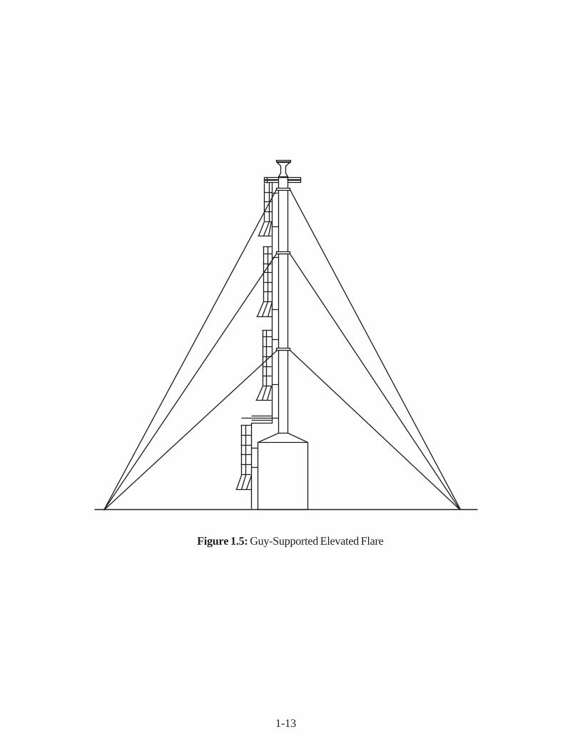
For safety reasons a stack is used to elevate the flare. The flare must be located so that itdoes not present a hazard to surrounding personnel and facilities. Elevated flares can be self-supported (free-standing), guyed, or structurally supported by a derrick. Examples of these threetypes of elevated flares are shown in Figures 1.3, 1.4, and 1.5 for self-supported, derrick supported,and guy-supported flares, respectively. Self-supporting flares are generally used for lower flaretower heights (30-100 feet) but can be designed for up to 250 feet. Guy towers are designed forover 300 feet, while derrick towers are designed for above 200 feet.[4, 6, 7, 8, 9, 10]
Free-standing flares provide ideal structural support. However, for very high units thecosts increase rapidly. In addition, the foundation required and nature of the soil must be considered.
Derrick-supported flares can be built as high as required since the system load is spreadover the derrick structure. This design provides for differential expansion between the stack,piping, and derrick. Derrick-supported flares are the most expensive design for a given flareheight.
The guy-supported flare is the simplest of all the support methods. However, a considerableamount of land is required since the guy wires are widely spread apart. A rule of thumb for spacerequired to erect a guy-supported flare is a circle on the ground with a radius equal to the height ofthe flare stack.[6]

1-10
To Flare
Vapor
Inlet
Condensed/EntrainedLiquid
Liquid
To Storage
Figure 1.2: Typical Vertical Knock-out Drum

1-11
Figure 1.3: Self-Supported Elevated Flare

1-12
Figure 1.4: Derrick-Supported Elevated Flare
1-13
Figure 1.5: Guy-Supported Elevated Flare
1-14
1.2.5 Gas Seal
Air may tend to flow back into a flare stack due to wind or the thermal contraction of stackgases and create an explosion potential. To prevent this, a gas seal is typically installed in the flarestack. One type of gas seal (also referred to as a flare seal, stack seal, labyrinth seal, or gasbarrier) is located below the flare tip to impede the flow of air back into the flare gas network.There are also “seals” which act as orifices in the top of the stack to reduce the purge gas volumefor a given velocity and also interfere with the passage of air down the stack from the upper rim.These are known by the names “internal gas seal, fluidic-seal, and arrestor seal”.[5] These sealsare usually proprietary in design, and their presence reduces the operating purge gas requirements.
1.2.6 Burner Tip
The burner tip, or flare tip, is designed to give environmentally acceptable combustion ofthe vent gas over the flare system’s capacity range. The burner tips are normally proprietary indesign. Consideration is given to flame stability, ignition reliability, and noise suppression. Themaximum and minimum capacity of a flare to burn a flared gas with a stable flame (not necessarilysmokeless) is a function of tip design. Flame stability can be enhanced by flame holder retentiondevices incorporated in the flare tip inner circumference. Burner tips with modern flame holderdesigns can have a stable flame over a flare gas exit velocity range of 1 to 600 ft/sec.[2] The actualmaximum capacity of a flare tip is usually limited by the vent stream pressure available to overcomethe system pressure drop. Elevated flares diameters are normally sized to provide vapor velocitiesat maximum throughput of about 50 percent of the sonic velocity of the gas subject to the constraintsof CFR 60.18.[l]
1.2.7 Pilot Burners
EPA regulations require the presence of a continuous flame. Reliable ignition is obtainedby continuous pilot burners designed for stability and positioned around the outer perimeter of theflare tip. The pilot burners are ignited by an ignition source system, which can be designed foreither manual or automatic actuation. Automatic systems are generally activated by a flame detectiondevice using either a thermocouple, an infra-red sensor or, more rarely, (for ground flare applications)an ultra-violet sensor.[4]
1.2.8 Steam Jets
A diffusion flame receives its combustion oxygen by diffusion of air into the flame from thesurrounding atmosphere. The high volume of fuel flow in a flare may require more combustion airat a faster rate than simple gas diffusion can supply. High velocity steam injection nozzles, positioned

1-15
around the outer perimeter of the flare tip, increase gas turbulence in the flame boundary zones,drawing in more combustion air and improving combustion efficiency. For the larger flares, steamcan also be injected concentrically into the flare tip.
The injection of steam into a flare flame can produce other results in addition to airentrainment and turbulence. Three mechanisms in which steam reduces smoke formation havebeen presented.[1] Briefly, one theory suggests that steam separates the hydrocarbon molecule,thereby minimizing polymerization, and forms oxygen compounds that burn at a reduced rate andtemperature not conducive to cracking and polymerization. Another theory claims that watervapor reacts with the carbon particles to form CO, CO
2, and H
2, thereby removing the carbon
before it cools and forms smoke. An additional effect of the steam is to reduce the temperature inthe core of the flame and suppress thermal cracking.[5] The physical limitation on the quantity ofsteam that can be delivered and injected into the flare flame determines the smokeless capacity ofthe flare. Smokeless capacity refers to the volume of gas that can be combusted in a flare withoutsmoke generation. The smokeless capacity is usually less than the stable flame capacity of theburner tip.
Significant disadvantages of steam usage are the increased noise and cost. Steam aggravatesthe flare noise problem by producing high-frequency jet noise. The jet noise can be reduced bythe use of small multiple steam jets and, if necessary, by acoustical shrouding. Steam injection isusually controlled manually with the operator observing the flare (either directly or on a televisionmonitor) and adding steam as required to maintain smokeless operation. To optimize steam usageinfrared sensors are available that sense flare flame characteristics and adjust the steam flow rateautomatically to maintain smokeless operation. Automatic control, based on flare gas flow andflame radiation, gives a faster response to the need for steam and a better adjustment of thequantity required. If a manual system is used, steam metering should be installed to significantlyincrease operator awareness and reduce steam consumption.
1.2.9 Controls
Flare system control can be completely automated or completely manual. Components ofa flare system which can be controlled automatically include the auxiliary gas, steam injection, andthe ignition system. Fuel gas consumption can be minimized by continuously measuring the ventgas low rate and heat content (Btu/scf) and automatically adjusting the amount of auxiliary fuel tomaintain the required minimum of 300 Btu/scf for steam-assisted flares. Steam consumption canlikewise be minimized by controlling flow based on vent gas flow rate. Steam flow can also becontrolled using visual smoke monitors. Automatic ignition panels sense the presence of a flamewith either visual or thermal sensors and reignite the pilots when flameouts occur.
1-16
1.3 Design Procedures
Flare design is influenced by several factors, including the availability of space, thecharacteristics of the flare gas (namely composition, quantity, and pressure level) and occupationalconcerns. The sizing of flares requires determination of the required flare tip diameter and height.The emphasis of this section will be to size a steam-assisted elevated flare for a given application.
1.3.1 Auxiliary Fuel Requirement
The flare tip diameter is a function of the vent gas flow rate plus the auxiliary fuel and purgegas flow rate. The purge gas flow rate is very small relative to the vent gas and fuel flow rates, soit may be ignored when determining the tip diameter. The flow rate of the auxiliary fuel, if required,is significant, and must be calculated before the tip diameter can be computed.
Some flares are provided with auxiliary fuel to combust hydrocarbon vapors when a leanflare gas stream falls below the flammability range or heating value necessary to sustain a stableflame. The amount of fuel required, F, is calculated based on maintaining the vent gas stream netheating value at the minimum of 300 Btu/scf required by rules defined in the Federal Register (seenext section):
( )Q B + F B = Q + FB tu
scfv f 300
(1.2)
where
Q = the vent stream flow rate, scfmB
v and B
f are the Btu/scf of the vent stream and fuel, respectively.
Rearranging gives:
F sc fm Q B
Bv
f
( ) = -
-
300
300
(1.3)
The annual auxiliary fuel requirement, Fa, is calculated by:
F F Fa M scf
y r = scfm
m in
h r
h r
y r =
scfm
yr
( ) 60 8760 526 (1.4)

1-17
Typical natural gas has a net heating value of about 1,000 Btn/scf. Automatic control ofthe auxiliary fuel is ideal for processes with large fluctuations in VOC compositions. These flaresare used for the disposal of such streams as sulfur tail gases and ammonia waste gases, as well asany low Btu vent streams.[2]
1.3.2 Flare Tip Diameter
Flare tip diameter is generally sized on a velocity basis, although pressure drop must alsobe checked. Flare tip sizing for flares used to comply with EPA air emission standards is governedby rules defined in the Federal Register (see 40 CFR 60.18). To comply with these requirements,the maximum velocity of a steam-assisted elevated flare is given in Table 1.1:
Table 1.1: Maximum Velocity of Steam-Assisted Elevated Flare
Net Heating Value of Maximum VelocityVent Stream Bv (Btu/scf) Vmax(ft/sec)
300 300 - 1,000 > 1,000
By determining the maximum allowed velocity, Vmax
(ft/sec), and knowing the total volumetricflow rate, Q
tot (acfm), including vent stream and auxiliary fuel gas, a minimum flare tip diameter,
Dmin
(in), can be calculated. It is standard practice to size the flare so that the design velocity offlow rate Q
tot, is 80 percent of V
max, i.e.:
( )D in =
V
sec
m in
m in ( ).
.12
4
60
0 81 95
πQ
Q
V
tot
m ax
to t
m ax
= (1.5)
where
Qtot
= Q + F (measured at stream temperature and pressure)
log VB
m axv
10
1 214
852 =
( )
( , )+
1-18
The flare tip diameter, D, is the calculated diameter, D = Dmin
, rounded up to the next commerciallyavailable size. The minimum flare size is 1 inch; larger sizes are available in 2-inch increments from2 to 24 inches and in 6-inch increments above 24 inches. The maximum size commercially availableis 90 inches.[5]
A pressure drop calculation is required at this point to ensure that the vent stream hassufficient pressure to overcome the pressure drop occurring through the flare system at maximumflow conditions. The pressure drop calculation is site specific but must take into account lossesthrough the collection header and piping, the knock-out drum, the liquid seal, the flare stack, thegas seal, and finally the flare tip. Piping size should be assumed equal to the flare tip diameter.Schedule 40 carbon steel pipe is typically used. If sufficient pressure is not available, the economicsof either a larger flare system (pressure drop is inversely proportional to the pipe diameter) or amover such as a fan or compressor must be weighed. (Refer to Section 1.3.8 for typical pressuredrop relationships.)
1.3.3 Flare Height
The height of a flare is determined based on the ground level limitations of thermal radiationintensity, luminosity, noise, height of surrounding structures, and the dispersion of the exhaust gases.In addition, consideration must also be given for plume dispersion in case of possible emissionignition failure. Industrial flares are normally sized for a maximum heat intensity of 1,500-2,000Btu/hr-ft2 when flaring at their maximum design rates.[1,2] At this heat intensity level, workers canremain in the area of the flare for a limited period only. If, however, operating personnel arerequired to remain in the unit area performing their duties, the recommended design flare radiationlevel excluding solar radiation is 500 Btu/hr-ft2.[1] The intensity of solar radiation is in the range of250-330 Btu/hr-ft2.[1] Flare height may also be determined by the need to safely disperse thevent gas in case of flameout. The height in these cases would be based on dispersion modeling forthe particular installation conditions and is not addressed here. The minimum flare height normallyused is 30 feet.[5] Equation (1.6) by Hajek and Ludwig may be used to determine the minimumdistance, L, required from the center of the flare flame and a point of exposure where thermalradiation must be limited.[1]
Lf R
K2 2
4 ft = ( )
τπ
(1.6)
where
J = fraction of heat intensity transmittedf = fraction of heat radiatedR = net heat release (Btu/hr)K = allowable radiation (500 Btu/hr-ft2)

1-19
The conservative design approach used here ignores wind effects and calculates the distanceassuming the center of radiation is at the base of the flame (at the flare tip), not in the center. It isalso assumed that the location where thermal radiation must be limited is at the base of the flare.Therefore, the distance, L, is equal to the required flare stack height (which is a minimum of 30feet). The f factor allows for the fact that not all the heat released in a flame can be released asradiation. Heat transfer is propagated through three mechanisms: conduction, convection, andradiation. Thermal radiation may be either absorbed, reflected, or transmitted. Since the atmosphereis not a perfect vacuum, a fraction of the heat radiated is not transmitted due to atmosphericabsorption (humidity, particulate matter). For estimating purposes, however, assume all of theheat radiated is transmitted (i.e., r = 1). Table 1.2 is a summary of heat radiated from variousgaseous diffusion flames:[1]
Table 1.2: Heat from Various Gaseous Difusion Flames
Gas Flare Tip Diameter (in) Fraction of Heat Radiated (f)
Hydrogen <1 .101.6 .113.3 1.68.0 1.516.0 1.7
Butane<1 .291.6 .293.3 .298.0 .2816.0 .30
Methane<1 .161.6 .163.3 .15
Natural Gas8.0 .1916.0 .23
1-20
In general, the fraction of heat radiated increases as the stack diameter increases. Ifstream-specific data are not available, a design basis of f = 0.2 will give conservative results.[4]The heat release, R, is calculated from the flare gas flow rate, W, and the net heating value, B
v, as
follows:
R W B v B tu
h r =
lb
h r
B tu
lb
(1.7)
1.3.4 Purge Gas Requirement
The total volumetric flow to the flame must be carefully controlled to prevent low flowflashback problems and to avoid flame instability. Purge gas, typically natural gas, N
2, or CO
2, is
used to maintain a minimum required positive flow through the system. If there is a possibility of airin the flare manifold, N
2, another inert gas, or a flammable gas must be used to prevent the formation
of an explosive mixture in the flare system. To ensure a positive flow through all flare components,purge gas injection should be at the farthest upstream point in the flare transport piping.
The minimum continuous purge gas required is determined by the design of the stack seals,which are usually proprietary devices. Modern labyrinth and internal gas seals are stated to requirea gas velocity of 0.001 to 0.04 ft/sec (at standard conditions).[6, 7, 8, 9, 10] Using the conservativevalue of 0.04 ft/sec and knowing the flare diameter (in), the annual purge gas volume, F
pu, can be
calculated:
FM
D
DM
pu scf
y r =
ft ft
sec
h r
h r
y r
scf
y r
=
0 04 4144
3 600 8 760
6 88
2
2
2
.sec
, ,
.
π
(1.8)
There is another minimum flare tip velocity for operation without burn lock or instability. Thisminimum velocity is dependent on both gas composition and diameter and can range frominsignificant amounts on small flares to 0.5 ft/sec on greater than 60-inch diameter units.[5]
Purge gas is also required to clear the system of air before startup, and to prevent avacuum from pulling air back into the system after a hot gas discharge is flared. (The cooling ofgases within the flare system can create a vacuum.) The purge gas consumption from these uses isassumed to be minor.
1-21
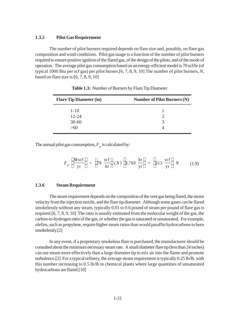
1.3.5 Pilot Gas Requirement
The number of pilot burners required depends on flare size and, possibly, on flare gascomposition and wind conditions. Pilot gas usage is a function of the number of pilot burnersrequired to ensure positive ignition of the flared gas, of the design of the pilots, and of the mode ofoperation. The average pilot gas consumption based on an energy-efficient model is 70 scf/hr (oftypical 1000 Btu per scf gas) per pilot burner.[6, 7, 8, 9, 10] The number of pilot burners, N,based on flare size is:[6, 7, 8, 9, 10]
Table 1.3: Number of Burners by Flam Tip Diameter
Flare Tip Diameter (in) Number of Pilot Burners (N)
1-10 112-24 230-60 3>60 4
The annual pilot gas consumption, Fpi is calculated by:
F N Npi M scf
y r =
scf
h r
h r
y r =
scf
y r
70 8 760 613( ) , (1.9)
1.3.6 Steam Requirement
The steam requirement depends on the composition of the vent gas being flared, the steamvelocity from the injection nozzle, and the flare tip diameter. Although some gases can be flaredsmokelessly without any steam, typically 0.01 to 0.6 pound of steam per pound of flare gas isrequired.[6, 7, 8, 9, 10] The ratio is usually estimated from the molecular weight of the gas, thecarbon-to-hydrogen ratio of the gas, or whether the gas is saturated or unsaturated. For example,olefins, such as propylene, require higher steam ratios than would paraffin hydrocarbons to burnsmokelessly.[2]
In any event, if a proprietary smokeless flare is purchased, the manufacturer should beconsulted about the minimum necessary steam rate. A small diameter flare tip (less than 24 inches)can use steam more effectively than a large diameter tip to mix air into the flame and promoteturbulence.[2] For a typical refinery, the average steam requirement is typically 0.25 lb/lb, withthis number increasing to 0.5 lb/lb in chemical plants where large quantities of unsaturatedhydrocarbons are flared.[10]

1-22
For general consideration, the quantity of steam required, S, can be assumed to be 0.4pounds of steam per pound of flare gas, W Using a 0.4 ratio, the amount of steam required is:
S Wlb s
y r =
lb steam
lb flare gas
lb
y r
h r
y r
0 4 8 760. , (1.10)
Operating a flare at too high a steam-to-gas ratio is not only costly, but also results in alower combustion efficiency and a noise nuisance. The capacity of a steam-assisted flare to burnsmokelessly may be limited by the quantity of steam that is available.
1.3.7 Knock-out Drum
As explained previously, the knock-out drum is used to remove any liquids that may be inthe vent stream. Two types of drums are used: horizontal and vertical. The economics of vesseldesign influences the choice between a horizontal and a vertical drum. When a large liquid storagevessel is required and the vapor flow is high, a horizontal drum is usually more economical. Verticalseparators are used when there is small liquid load, limited plot space, or where ease of levelcontrol is desired. It is assumed here that the drum is not sized for emergency releases and thatliquid flow is minimal. Flares designed to control continuous vent streams generally have verticalknockout drums, whereas emergency flares typically have horizontal vessels. The proceduredescribed below applies to vertical drums exclusively. A typical vertical knock-out drum is presentedin Figure 1.2.
Liquid particles will separate when the residence time of the vapor is greater than the timerequired to travel the available vertical height at the dropout velocity of the liquid particles, i.e., thevelocity is less than the dropout velocity. In addition, the vertical gas velocity must be sufficientlylow to permit the liquid droplets to fall. Since flares are designed to handle small-sized liquiddroplets, the allowable vertical velocity is based on separating droplets from 300 to 600 micrometersin diameter.[1] The dropout velocity, U, of a particle in a stream, or the maximum design vaporvelocity, is calculated as follows:[11]
U G v
v
ft
sec =
-
ρ ρρ
1(1.11)
where
G = design vapor velocity factorp
l and p
v= liquid and vapor densities, lb/ft3

1-23
Note that in most cases,
ρ ρρ
ρρ
1 1 - v
v v
≈ (1.11a)
The design vapor velocity factor, G, ranges from 0.15 to 0.25 for vertical gravity separators at85% of flooding.[11]
Once the maximum design vapor velocity has been determined the minimum vessel cross-sectional area, A, can be calculated by:
AQ
U
a
ft =
ftm in
ftsec
2( )secm in
60
(1.12)
where Qn is the vent stream flow in actual ft3/min, or Q adjusted to the vent stream temperature and
pressure.
The vessel diameter, dmin
, is then calculated by:
d Am in = 4π (1.13)
In accordance with standard head sizes, drum diameters in 6-inch increments are assumed so:
( )d = d rounde d to the nex t la rgest s izem in (1.14)
Some vertical knockout drums are sized as cyclones and utilize a tangential inlet to generatehorizontal separating velocities. Vertical vessels sized exclusively on settling velocity (as in theparagraph above) will be larger than those sized as cyclones.[5]
The vessel thickness, t, is determined from the diameter as showen in Table 1.4 [15].Proper vessel height, h, is usually determined based on required liquid surge volume. The calculatedheight is then checked to verify that the height-to-diameter ratio is within the economic range of 3to 5.[11] For small volumes of liquid, as in the case of continuous VOC vent control, it is necessaryto provide more liquid surge than is necessary to satisfy the h/d > 3 condition. So for purposes offlare knock-out drum sizing:
h d = 3 (1.15)

1-24
Table 1.4: Vessel Thickness based on Diameter
Diameter, d (inches) Thickness, t (inches)
d<36 0.2536<d<72 0.3772<d<108 50.5108<d<144 0.75d>144 1.0
1.3.8 Gas Mover System
The total system pressure drop is a function of the available pressure of the vent stream,the design of the various system components, and the flare gas flow rate. The estimation of actualpressure drop requirements involves complex calculations based on the specific system’s vent gasproperties and equipment used. For the purposes of this section, however, approximate valuescan be used. The design pressure drop through the flare tip can range from 0.1 to 2 psi with thefollowing approximate pressure drop relationships:[5] The total system pressure drop rangesfrom about 1 to 25 psi.[5]
Table 1.5: Design Pressure Losses through the Flare Tip
Equipment Approximate Pressure Loss
Gas seal: 1 to 3 times flare tip pressure drop
Stack: 0.25 to 2 times flare tip pressure drop
Liquid seal and Knock 1 to 1.5 times flare tip pressure drop plusout drum: pressure drop due to liquid depth in the seal, which
is normally 0.2 to 1.5 psi.
Gas collection system: calculated based on diameter, length, and flow.System is sized by designer to utilize the pressuredrop available and still leave a pressure at the stackbase of between 2 and 10 psi.
1-25
1.4 Estimating Total Capital Investment
The capital costs of a flare system are presented in this section and are based on thedesign/sizing procedures discussed in Section 7.3. The costs presented are in September 2000dollars.1 The capital costs for this Chapter were updated through vender contacts in the summer of2000. The costs were updated by sending vendors tables and graphs of previous cost equationsand asking for updated information.
Vendors reported that costs had not increased subastantially since 1990, the primaryreasons cited for stable prices ere increased competitions and lower steel prices. One vendorreported slight price increases over the period and another reported slight price decreases. Vendorsagreed that the costs developed in 1990 reflected current market conditions. Items not such asplatforms and ladders could result in some variation around these prices. Based on the informationsupplied by the vendors, the 1990 prices are carried forward for the year 2000 and are presentedin Tables 1.6 to 1.8 and Figures 1.5 to 1.7. [2][7]
Total capital investment, TCI, includes the equipment costs, EC, for the flare itself, thecost of auxiliary equipment, the cost of taxes, freight, and instrumentation, and all direct and indirectinstallation costs.
The capital cost of flares depends on the degree of sophistication desired (i.e., manual vsautomatic control) and the number of appurtenances selected, such as knock-out drums, seals,controls, ladders, and platforms. The basic support structure of the flare, the size and height, andthe auxiliary equipment are the controlling factors in the cost of the flare. The capital investmentwill also depend on the availability of utilities such as steam, natural gas, and instrument air.
The total capital investment is a battery limit cost estimate and does not include the provisionsfor bringing utilities, services, or roads to the site, the backup facilities, the land, the research anddevelopment required, or the process piping and instrumentation interconnections that may berequired in the process generating the waste gas. These costs are based on a new plant installation;no retrofit cost considerations such as demolition, crowded construction working conditions,scheduling construction with production activities, and long interconnecting piping are included.These factors are so site-specific that no attempt has been made to provide their costs.
1.4.1 Equipment Costs
Flare vendors were asked to provide budget estimates for the spectrum of commercialflare sizes. These quotes [6, 7, 8, 9, 10] were used to develop the equipment cost correlations forflare units, while the cost equations for the auxiliary equipment were based on references [12] and
1For information on escalating these prices to more current dollars, refer to the EPA report Escalation Indexesfor Air Pollution Control Costs and updates thereto, all of which are installed on the OAQPS TechnologyTransfer Network (CTC Bulletin Board).

1-26
[13] (knock-out drums) and [14] and [15] (piping). The expected accuracy of these costs is ±30% (i.e., “study” estimates). Keeping in mind the height restrictions discussed in Section 7.2.4,these cost correlations apply to flare tip diameters ranging from 1 to 60 inches and stack heightsranging from 30 to 500 feet. The standard construction material is carbon steel except when it isstandard practice to use other materials, as is the case with burner tips.
The flare costs, CF presented in Equations 1.16 through 1.18 are calculated as a function
of stack height, L (ft) (30 ft minimum), and tip diameter, D (in), and are based on support type asfollows:
Self Support Group:
C D LF ($ ) ( . . . ) = + + 78 0 9 14 0 749 2 (1.16)
Guy Support Group:
C D LF = + + ($ ) ( . . )103 8 68 0 470 2 (1.17)
Derrick Support Group:
C D LF ($ ) ( . . . ) = + + 76 4 2 72 1 64 2 (1.18)
The equations are least-squares regression of cost data provided by different vendors. Itmust be kept in mind that even for a given flare technology (i.e., elevated, steam-assisted), designand manufacturing procedures vary from vendor to vendor, so that costs may vary. Once a studyestimate is completed, it is recommended that several vendors be solicited for more detailed costestimates.
Each of these costs includes the flare tower (stack) and support, burner tip, pilots, utility(steam, natural gas) piping from base, utility metering and control, liquid seal, gas seal, and galvanizedcaged ladders and platforms as required. Costs are based on carbon steel construction, exceptfor the upper four feet and burner tip, which are based on 310 stainless steel.
The gas collection header and transfer line requirements are very site specific and dependon the process facility where the emission is generated and on where the flare is located. For thepurposes of estimating capital cost it is assumed that the transfer line will be the same diameter asthe flare tip[6] and will be 100 feet long. Most installations will require much more extensivepiping, so 100 feet is considered a minimum.
The costs for vent stream piping, Cp, are presented separately in Equation 1.19 or 1.20
and are a function of pipe, or flare, diameter D.[15]

1-27
C D w h ere Dp = ($ ) ( ).127 1 241 21 ′′ < < ′′ (1.19)
C D w here D p ($ ) ( ). = 139 30 601 07 ′′ < < ′′ (1.20)
The costs, Cp, include straight, Schedule 40, carbon steel pipe only, are based on 100 feet of
piping, and are directly proportional to the distance required.
The costs for a knock-out drum, CK, are presented separately in Equation 7.22 and are a
function of drum diameter, d (in), and height, h (in).[12, 13]
C dt h dK = + ($ ) . [ ( . ) ] .14 2 0 812 0 737 (1.21)
where t is the vessel thickness, in inches, determined based on the diameter.
Flare system equipment cost, EC, is the total of the calculated flare, knock-out drum, andpiping costs.
E C C + C + CF K p =($ ) (1.22)
Purchased equipment costs, PEC, is equal to equipment cost, EC, plus factors for ancillaryinstrumentation (i.e., control room instruments) (.10), sales taxes (0.03), and freight (0.05) or,
( )P E C ($ ) = E C 1 + 0 .10 + 0 .03 + 0 .05 = 1 .18 E C (1.23)
1.4.2 Installation Costs
The total capital investment, TCI, is obtained by multiplying the purchased equipmentcost, PEC, by an installation factor of 1.92.
T C I P E C ($ ) = 1 .92 (1.24)
These costs were determined based on the factors in Table 1.6. The bases used in calculatingannual cost factors are given in Table 1.5. These factors encompass direct and indirect installationcosts. Direct installation costs cover foundations and supports, equipment handling and erection,piping, insulation, painting, and electrical. Indirect installation costs cover engineering, constructionand field expenses, contractor fees, start-up, performance testing, and contingencies. Depending

1-28
on the site conditions, the installation costs for a given flare could deviate significantly from costsgenerated by these average factors. Vatavuk and Neveril provide some guidelines for adjusting theaverage installation factors to account for other-than-average installation conditions .[1]
The use of steam as a smoke suppressant can represent as much as 90% or more of the total directannual costs.
Table 1.6: Self-Supporting Flare Costs
D (Diameter in Inches) Hf (Hight in Feet) Year 2000 (In Dollars)12 30 $44,16312 40 $47,36712 50 $50,68412 60 $54,11212 70 $57,65312 80 $61,30612 90 $65,07112 100 $68,948
24 30 $102,29124 40 $107,13824 50 $112,09824 60 $117,16924 70 $122,35324 80 $127,64924 90 $133,05724 100 $138,578
0
20
40
60
80
100
120
140
160
30 40 50 60 70 80 90 100
Height (feet)
Co
st
(th
ou
san
ds
$)
24in.
12 in.
Figure 1.5: Capital Costs of Self-supporting Flares for 12 in. and 24 in. Diameters

1-29
Table 1.7: Guy-Supported Flare Costs
Df (Diameter in Inches) Hf (Height in Feet) Year 2000 (In Dollars)24 50 $112,10424 100 $128,39324 150 $145,78724 200 $164,28424 250 $183,88724 300 $204,59324 250 $183,88724 400 $249,32024 450 $273,341
48 50 $295,00148 100 $321,08148 150 $348,26548 200 $376,55448 250 $405,94748 300 $436,44548 250 $405,94748 300 $436,44548 250 $405,94748 400 $500,75448 450 $534,566
Figure 1.6: Captial Costs of Guy-Supported Flares for 24 in. and 48 in. Diameters
0
100
200
300
400
500
600
50 100 150 200 250 300 350 400 450
Height (feet)
Co
st
(th
ou
san
ds
$)
48"
24"

1-30
Table 1.8: Derrick Supported Flare Costs
Df (Diameter in Inches) Hf (Height in Feet) Year 2000 (In Dollars)36 200 $252,32536 250 $341,43036 300 $443,98236 350 $559,98336 400 $689,43136 450 $832,32836 500 $988,67236 550 $1,158,46536 600 $1,341,705
54 200 $303,91054 250 $401,04454 300 $511,62554 350 $635,65554 400 $773,13354 450 $924,05954 500 $1,088,43354 550 $1,266,25554 600 $1,457,525
Figure 1.7: Captial Costs of Derrick-Supported Flares for 36 in. and 54 in. Diameters
0
200
400
600
800
1,000
1,200
1,400
1,600
200 250 300 350 400 450 500 550 600
Height (feet)
Co
st
(th
ou
san
ds
$) 54"36"
1-31
1.5 Estimating Total Annual Costs
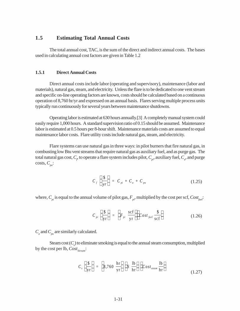
The total annual cost, TAC, is the sum of the direct and indirect annual costs. The basesused in calculating annual cost factors are given in Table 1.2
1.5.1 Direct Annual Costs
Direct annual costs include labor (operating and supervisory), maintenance (labor andmaterials), natural gas, steam, and electricity. Unless the flare is to be dedicated to one vent streamand specific on-line operating factors are known, costs should be calculated based on a continuousoperation of 8,760 hr/yr and expressed on an annual basis. Flares serving multiple process unitstypically run continuously for several years between maintenance shutdowns.
Operating labor is estimated at 630 hours annually.[3] A completely manual system couldeasily require 1,000 hours. A standard supervision ratio of 0.15 should be assumed. Maintenancelabor is estimated at 0.5 hours per 8-hour shift. Maintenance materials costs are assumed to equalmaintenance labor costs. Flare utility costs include natural gas, steam, and electricity.
Flare systems can use natural gas in three ways: in pilot burners that fire natural gas, incombusting low Btu vent streams that require natural gas as auxiliary fuel, and as purge gas. Thetotal natural gas cost, C
f, to operate a flare system includes pilot, C
pi, auxiliary fuel, C
a, and purge
costs, Cpu
:
Cyr
C + C + Cf pi a pu = $
(1.25)
where, Cpi is equal to the annual volume of pilot gas, F
pi, multiplied by the cost per scf, Cost
fuel:
C F C ostpi p i fue l $
y r =
scf
y r
$
scf
(1.26)
Ca and C
pu are similarly calculated.
Steam cost (Cs) to eliminate smoking is equal to the annual steam consumption, multiplied
by the cost per lb, CostStream
:
C S C osts steam $
y r =
h r
y r
lb
h r
lb
h r
8 760,
(1.27)

1-32
1.5.2 Indirect Annual Costs
The indirect (fixed) annual costs include overhead, capital recovery, administrative (G &A) charges, property taxes, and insurance. Suggested indirect annual cost factors are presented inTable 1.9.
Overhead is calculated as 60% of the total labor (operating, maintenance, and supervisory)and maintenance material costs. Overhead cost is discussed in Section 1 of this Manual.
Table 1.9: Capital Cost Factors for Flare Systems
Cost Item Factor
Direct CostsPurchased equipment costs Flare system, EC As estimated, A Instrumentation 0.10 A Sales taxes 0.03 A Freight 0.05 A
Purchased equipment cost, PEC B = 1.18 A
Direct installation costsFoundations & supports 0.12 BHandling & erection 0.40 BElectrical 0.01 BPiping 0.02 BInsulation 0.01 BPainting 0.01 B
Direct installation costs 0.57 B
Site preparationAs required, SP
BuildingsAs required, Bldg.
Total Direct Costs, DC 1.57 B + SP + Bldg.
Indirect Annual Costs, DCEngineering 0.10 BConstruction and Field expenses 0.10 BContractor fees 0 BStart-up 0.01 BPerformance test 0.01 BContingencies 0.03 B
Total Indirect Costs, IC 0.35 B
Total Capital Investment = DC + IC 1.92 B + SP + Bldg.

1-33
The system capital recovery cost, CRC, is based on an estimated 15-year equipment life.(See Section 1 of this Manual for a thorough discussion of the capital recovery cost and thevariables that determine it.) For a 15-year life and an interest rate of 7%, the capital recoveryfactor is 0.1098. The system capital recovery cost is the product of the system capital recoveryfactor, CRF, and the total capital investment, TCI, or:
C R C C R F T C I T C I $
y r = =
× ×0 1098. (1.28)
As shown in Table 1.10, G & A, taxes, and insurance can be estimated at 2%, 1%, and 1% of thetotal capital investment, TCI, respectively.
Table 1.10: Suggested Annual Cost Factors for Flare Systems
Cost Item Factor
Direct Annual Costs, DCOperating labor{3}Operator 630 man-hours/yearSupervisor 15% of operator
Operating materials -
MaintenanceLabor ½ hour per shiftMaterial 100% of maintenance labor
UtilitiesElectricity All utilities equal to:Purge gas (Consumption rate) xPilot gas (Hours/yr) x (unit cost)Auxiliary fuelSteam
Indirect Annual Costs, ICOverhead 60% of total labor and material costsAdministrative charges 2% of Total Capital InvestmentProperty tax 1% of Total Capital InvestmentInsurance 1% of Total Capital InvestmentCapital recoverya 0.1315 x Total Capital Investment
Total Annual Cost Sum of Direct and Indirect Annual Costs
aSee Chapter 2.

1-34
1.6 Example Problem
The example problem described in this section shows how to apply the flare sizing andcosting procedures to the control of a vent stream associated with the distillation manufacturing ofmethanol.
1.6.1 Required Information for Design
The first step in the design procedure is to determine the specifications of the vent gas tobe processed. The minimum information required to size a flare system for estimating costs are thevent stream:
Volumetric or mass flow rateHeating value or chemical compositionTemperatureSystem pressureVapor and liquid densities
In addition the following are needed to calculate direct annual costs.
Labor costsFuel costs
Steam costs
Vent stream parameters and cost data to be used in this example problem are listed in Table 1.11.
1.6.2 Capital Equipment
The first objective is to properly size a steam-assisted flare system to effectively destroy98% of the VOC (methanol) in the vent gas stream. Using the vent stream parameters and thedesign procedures outlined in Section 1.3, flare and knock-out drum heights and diameters can bedetermined. Once equipment has been specified, the capital costs can be determined from equationspresented in Section 1.4.1.

1-35
1.6.2.1 Equipment Design
The first step in flare sizing is determining the appropriate flare tip diameter. Knowing thenet (lower) heating value of the vent stream, the maximum allowed velocity can be calculated fromthe Federal Register requirements. Since the heating value is in the range of 300 to 1,000 Btu/scf,the maximum velocity, V
max, is determined by Equation 1.1.
log V .
V
10 m ax
m ax
=
B tuscf
+ =
= ft
sec
449 1 214
8521 95
89 5
,
.
Table 1.11: Example Problem Data
Vent Stream ParametersFlow rate 63.4 acfma
399.3 lb/hrHeat content 449 Btu/scfb
System pressure 10 psigc
Temperature 90 oFLiquid density[17] 49.60 lb/ft3d
Vapor density[17] 0.08446 lb/ft3d
Cost Data (March 1990)[18,19]Operating hours 8,760 hrs/yrNatural gas 3.03 $/1000 scfSteam 4.65 $/1000 lbsOperating labor 15.64 $/hrMaintenance labor 17.21 $/hr
aMeasured at flare tip. Flow rate has been adjusted to account for drop in pressure
from 10 psig at source to 1 psig at flare tip.bStandard conditions: 77oF, 1 atmosphere.cPressure at source (gas collection point). Pressure at flare tip is lower: 1 psig.dMeasured at standard conditions.
1-36
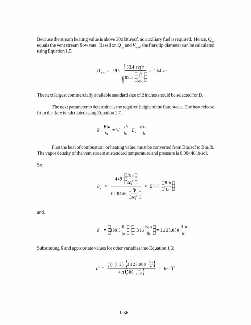
Because the stream heating value is above 300 Btu/scf, no auxiliary fuel is required. Hence, Qtot
equals the vent stream flow rate. Based on Qtot
and Vmax
, the flare tip diameter can be calculatedusing Equation 1.5.
D m in ..
..=
= sc fm
ft
sec
in1 9563 4
89 51 64
The next largest commercially available standard size of 2 inches should be selected for D.
The next parameter to determine is the required height of the flare stack. The heat releasefrom the flare is calculated using Equation 1.7.
R W B v
B tu
hr
lb
hr
B tu
lb=
First the heat of combustion, or heating value, must be converted from Btu/scf to Btu/lb.The vapor density of the vent stream at standard temperature and pressure is 0.08446 lb/scf.
So,
B v =
B tu
sc f
lb
sc f
= B tu
lb
449
0 08446
5316
.
and,
R =
=399 3 5 316 2 123 000. , , ,
lb
h r
B tu
lb
B tu
h r
Substituting R and appropriate values for other variables into Equation 1.6:
( )( )L2 2
1 0 2 2 123 000
4 50068=
−
= ft
B tuhr
B tu
h r ft2
( ) ( . ) , ,
π

1-37
Resulting in:
L = 8.2ft
Assuming the smallest commercially available flare is 30 feet, the flare height is set to this value, L= 30 ft.
Next the knock-out drum must be sized. Assuming a design vapor velocity factor, G, of0.20, and substituting the vapor and liquid densities of methanol into Equation 1.11 yields a maximumvelocity of:
U = = -
ft
sec0 20
49 60 0 08446
0 084464 84.
. .
..
Given a vent gas flow rate of 63.4 scfm, the minimum vessel cross-sectional, diameter is calculatedby Equation 1.12:
A = = acfm
ftft
sec
263 4
60 4 840 218
.
( ) ( . ).sec
m in
This results in a minimum vessel diameter of:
( )d m in = = 2in
ftft in1
40 218 6 32
π. .
The selected diameter, d, rounded to the next largest 6 inches is 12 inches. Using the rule of theheight to diameter ratio of three gives a vessel height of 36 inches, or 3 feet.
1.6.2.2 Equipment Costs
Once the required flare tip diameter and stack height have been determined the equipmentcosts can be calculated. Since the height is 30 feet, the flare will be self-supporting. The costs aredetermined from Equation 1.16.
C F ==
+ in ches + ft
[ . . ( ) . ( ) ]
$14 ,
78 0 9 14 2 0 749 30
100
2

1-38
Knock-out drum costs are determined using Equation 7.21, where t is determined from the rangesPresented in Section 7.3.7. Substituting 0.25 for t:
C K + = =14 2 12 0 25 36 0 812 12 0 737. [ ( ) ( . ) ( . ( ) ) ] $530.
Transport piping costs are determined using Equation 1.19.
C p = = 127 2 1 21( ) $290.
The total auxiliary equipment cost is the sum of the knock-out drum and transport piping costs, or:$530 + $290 = $820.
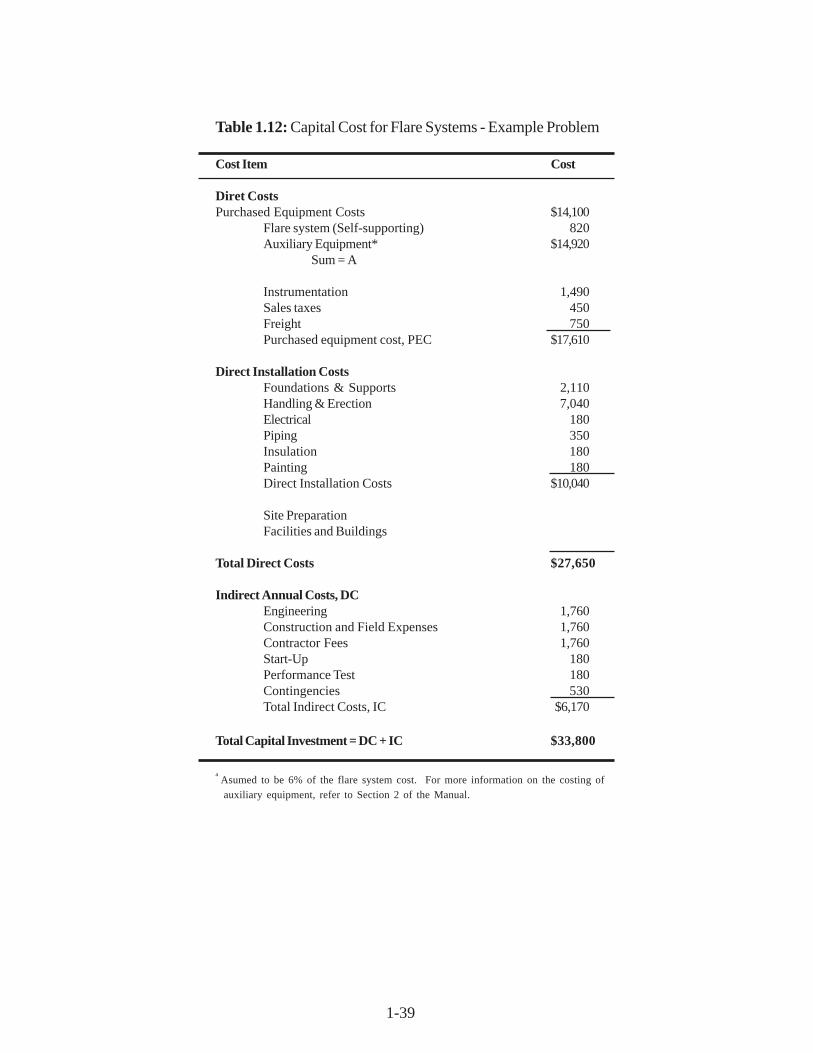
The total capital investment is calculated using the factors given in Table 1.9. The calculationsare shown in Table 1.12. Therefore:
P E C = × = 1 18 14 920 17 610. ( , ) $ ,
And:
T C I = × = 1 92 17 610 800. ( , ) $33,
1.6.3 Operating Requirements
Operating labor is estimated at 630 hours annually with supervisory labor at 15% of thisamount. Maintenance labor is estimated at 1/2 hour per shift. Maintenance material costs areassumed to be equal to maintenance labor costs.
As stated in Table 1.11, since the heat content of the example stream is above 300 Btu/scfno auxiliary fuel is needed. Natural gas is required, however, for purge and pilot gas. Purge gasrequirements are calculated from Equation 1.8.
F pu = in = M scf
yr6 88 2 27 52. ( ) .
1-39
Table 1.12: Capital Cost for Flare Systems - Example Problem
Cost Item Cost
Diret CostsPurchased Equipment Costs $14,100
Flare system (Self-supporting) 820Auxiliary Equipment* $14,920
Sum = A
Instrumentation 1,490Sales taxes 450Freight 750Purchased equipment cost, PEC $17,610
Direct Installation CostsFoundations & Supports 2,110Handling & Erection 7,040Electrical 180Piping 350Insulation 180Painting 180Direct Installation Costs $10,040
Site PreparationFacilities and Buildings
Total Direct Costs $27,650
Indirect Annual Costs, DCEngineering 1,760Construction and Field Expenses 1,760Contractor Fees 1,760Start-Up 180Performance Test 180Contingencies 530Total Indirect Costs, IC $6,170
Total Capital Investment = DC + IC $33,800
a Asumed to be 6% of the flare system cost. For more information on the costing of
auxiliary equipment, refer to Section 2 of the Manual.
1-40
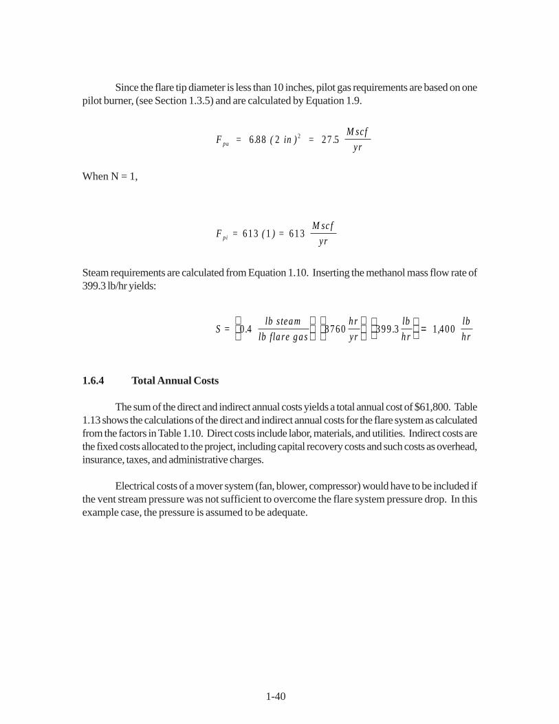
Since the flare tip diameter is less than 10 inches, pilot gas requirements are based on onepilot burner, (see Section 1.3.5) and are calculated by Equation 1.9.
F pu = in = M scf
yr6 88 2 27 52. ( ) .
When N = 1,
F = ( ) = M sc f
yrpi 613 1 613
Steam requirements are calculated from Equation 1.10. Inserting the methanol mass flow rate of399.3 lb/hr yields:
S = . lb s team
lb fla re gas
hr
yr.
lb
hr ,
lb
h r0 4 8760 399 3 1 400
=
1.6.4 Total Annual Costs
The sum of the direct and indirect annual costs yields a total annual cost of $61,800. Table1.13 shows the calculations of the direct and indirect annual costs for the flare system as calculatedfrom the factors in Table 1.10. Direct costs include labor, materials, and utilities. Indirect costs arethe fixed costs allocated to the project, including capital recovery costs and such costs as overhead,insurance, taxes, and administrative charges.
Electrical costs of a mover system (fan, blower, compressor) would have to be included ifthe vent stream pressure was not sufficient to overcome the flare system pressure drop. In thisexample case, the pressure is assumed to be adequate.

1-41
Table 1.13: Annual Costs for Flare System Example problem
Cost Item Calculations Cost
Direct Annual Costs, DC
Operating LaborOperator 630 h x $15.64 $ 9,850
year hSupervisor 15% of operator = 0.15 x 9,850 1,480Operating materialsMaintenanceLabor 0.5 h x shift x 8,760h x $17.21 9,420
shift 8 h yr h
Maintenance Material 100% of maintenance labor 9,420Utilities
ElectricityPurge gas Inserting the methanol mass flow rate of 399.3 lb/hr yields:
27.5 Mscf x $3.03 80 yr MscfPilot gas 613 Mscf x $3.03 1,860 yr MscfSteam 1,400 x 103lb x $4.65 6,510 yr 103lb
Total DC (rounded) $38,600
Indirect Annual Costs, ICOverhead 60% of total labor and material costs 18,100
= 0.6(9,850 + 1,480 + 9,420 + 9,420)Administrative charges 2% of Total Capital Investment = 0.02 ($33,800) 680Property tax 1% of Total Capital Investment = 0.01 ($33,800) 340Insurance 1% of Total Capital Investment = 0.01 ($33,800) 340Capital recoverya 0.1098 x $33,800 3,710
Total IC (rounded) 23,200
Total Annual Cost (rounded) $61,800
aThe capital recovery cost factor, CRF, is a function of the flare equipment life and the opportunity cost ofthe capital (i.e. interest rate). For example, for a 15 year equipment life and 7% interest rate, CRF = 0.1098.

1-42
1.7 Acknowledgments
The authors gratefully acknowledge the following companies for contributing data to this chapter:
• Flaregas Corporation (Spring Valley, NY)
• John Zink Company (Tulsa, OK)
• Kaldair Incorporated (Houston, TX)
• NAO Incorporated (Philadelphia, PA)
• Peabody Engineering Corporation (Stamford, CT)
• Piedmont HUB, Incorporated (Raleigh, NC)
References
[1] Guide for Pressure-Relieving and Depressurizing Systems, Refining Department,API Recommended Practice 521, Second Edition, September 1982.
[2] Kalcevic, V. (IT Enviroscience), “Control Device Evaluation Flares and the Use ofEmissions as Fuels”, Organic Chemical Manufacturing Volume 4; CombustionControl Devices, U.S. Environmental Protection Agency, Research Triangle Park, NC,Publication no. EPA-450/3-80-026, December 1980, Report 4.
[3] Reactor Processes in Synthetic Organic Chemical Manufacturing Industry-Back-ground Information for Proposed Standards, U.S. Environmental Protection Agency,Office of Air Quality Planning and Standards, Research Triangle Park, NC, PreliminaryDraft, EPA 450/3-90-016a, June 1990.
[4] Letter from J. Keith McCartney (John Zink Co., Tulsa, OK) to William M. Vatavuk(U.S. Environmental Protection Agency, Research Triangle Park, NC), November 19,1990.
[5] Letter from David Shore (Flaregas Corp., Spring Valley, NY) to William M. Vatavuk(U.S. Environmental Protection Agency, Research Triangle Park, NC), October 3,1990.
[6] Letter from Pete Tkatschenko (NAO, Inc., Philadelphia, PA) to Diana Stone (Radian,Research Triangle Park, NC), May 2, 1990.

1-43
[7] Letter to Gary Tyler (Kaldair, Inc., Houston, TX) to Diana Stone (Radian, ResearchTriangle Park, NC), April 10, 1990.
[8] Letter from Zahir Bozai (Peabody Engineering Corp., Stamford, CT) to Diana Stone(Radian, Research Triangle Park, NC), May 7, 1990.
[9] Letter from James Parker (John Zink Co., Tulsa, OK) to Diana Stone (Radian, Re-search Triangle Park, NC), April 17, 1990.
[10] Letter from Nick Sanderson (Flaregas Corp., Spring Valley, NY) to Diana Stone(Radian, Research Triangle Park, NC), May 2, 1990.
[11] Wu, F.H., “Drum Separator Design, A New Approach,” Chemical Engineering, April2, 1984, pp. 74-81.
[12] Mulet, A., “Estimate Costs of Pressure Vessels Via Correlations,” Chemical Engineer-ing, October 5, 1981, pp. 145-150.
[13] Process Plant Construction Estimating Standards, Richardson Engineering Services,Inc., Volume 4, 1988 Edition.
[14] Peters, Max S. and Klaus D. Timmerhaus, Plant Design and Economics for ChemicalEngineers, Third Edition, McGraw-Hill, 1980.
[15] Cost Information from Piedmont HUB, Incorporated, Raleigh, NC. August 1990.
[16] Vatavuk, W.M., and R. Neveril,”Estimating Costs of Air Pollution Control Systems,Part II: Factors for Estimating Capital and Operating Costs,: Chemical Engineering,November 3, 1980, pp. 157-162.
[17] Handbook of Chemistry and Physics, 55th Edition, CRC Press, 1974-1975.
[18] Green, G.P. and Epstein, R.K., Employment and Earnings, Department of Labor,Bureau of Labor Statistics, Volume 37, No.4, April 1990.
[19] Monthly Energy Review, Energy Information Administration, Office of EnergyMarkets and End Use, U.S. Department of Energy, DOE-EIA-0035(90/12), February1990.
TECHNICAL REPORT DATA(Please read Instructions on reverse before completing)
1. REPORT NO.
452/B-02-0012. 3. RECIPIENT'S ACCESSION NO.
4. TITLE AND SUBTITLE
The EPA Air Pollution Control Cost Manual
5. REPORT DATE
January, 2002 6. PERFORMING ORGANIZATION CODE
7. AUTHOR(S)
Daniel Charles Mussatti
8. PERFORMING ORGANIZATION REPORT NO.
9. PERFORMING ORGANIZATION NAME AND ADDRESS
U.S. Environmental Protection Agency Office of Air Quality Planning and Standards Air Quality Standards and Strategies Division Innovative Strategies and Economics Group Research Triangle Park, NC 27711
10. PROGRAM ELEMENT NO.
11. CONTRACT/GRANT NO.
12. SPONSORING AGENCY NAME AND ADDRESS
Director Office of Air Quality Planning and Standards Office of Air and Radiation U.S. Environmental Protection Agency Research Triangle Park, NC 27711
13. TYPE OF REPORT AND PERIOD COVERED
Final
14. SPONSORING AGENCY CODE
EPA/200/04
15. SUPPLEMENTARY NOTES
Updates and revises EPA 453/b-96-001, OAQPS Control Cost Manual, fifth edition (in English only)
16. ABSTRACT
In Spanish, this document provides a detailed methodology for the proper sizing and costing of numerous airpollution control devices for planning and permitting purposes. Includes costing for volatile organiccompounds (VOCs); particulate matter (PM); oxides of nitrogen (NOx); SO2, SO3, and other acid gasses;and hazardous air pollutants (HAPs).
17. KEY WORDS AND DOCUMENT ANALYSIS
a. DESCRIPTORS b. IDENTIFIERS/OPEN ENDED TERMS c. COSATI Field/Group
EconomicsCostEngineering costSizingEstimationDesign
Air Pollution controlIncineratorsAbsorbersAdsorbersFiltersCondensersElectrostatic PrecipitatorsScrubbers
18. DISTRIBUTION STATEMENT
Release Unlimited
19. SECURITY CLASS (Report)
Unclassified21. NO. OF PAGES
1,400
20. SECURITY CLASS (Page)
Unclassified22. PRICE
EPA Form 2220-1 (Rev. 4-77)EPA Form 2220-1 (Rev. 4-77) PREVIOUS EDITION IS OBSOLETE