section 5: specifications - home | gujarat state ... a particular clause or a part thereof in...
TRANSCRIPT

Section VII: Works Requirements
GSHP-II: Bidding Documents (ICB) 1
SECTION 5: SPECIFICATIONS

TECHNICAL SPECIFICATIONS 1.0 PREAMBLE
1.1 The Technical Specifications contained herein shall be read in conjunction with the other Bidding Documents as specified in this Volume.
1.2 Site Information
1.2.1 The information given hereunder and provided elsewhere is given in good faith by the Employer but the Contractor shall satisfy himself regarding all aspects of site conditions and no claim will be entertained on the plea that the information supplied by the Employer is erroneous or insufficient.
1.2.2 Longitude, Latitude, Wind Speed, Temperature
Contract Area Location (m) (Starting point)
Location (m) (Ending Point)
Wind Speed (Vb) Annual Average Temperature
Max. Min. Dhaboi – Bodeli 334456.86E
2449328.25N 367772.04E 2463815.56N
Vb=39 m/s (Moderate Damage risk zone)
44.2C 12.0C
Amod-Karjan 280809.34E 2433967.94N
306675.77E 2439233.54N
Vb=44m/s 44.2C 12.0C
1.2.3 Terrain, Rainfall, Humidity, Seismic Zones
Contract Area Terrain
(Elevation in m.)
Av. Rainfall 2001-2010*
Relative Humidity* Seismic
Zones* (mm) (%) Dhaboi – Bodeli 30-90 m 1024 70 to 75 Zone III
Amod-Karjan 30-90 m 928 65 to70 Zone III
2.0 GENERAL REQUIREMENTS
The Technical Specifications in accordance with which the entire work described hereinafter shall be constructed and completed by the Contractor shall comprise of the following:
2.1 Part - I - General Technical Specifications
The General Technical Specifications shall be the “SPECIFICATIONS FOR ROAD AND BRIDGE WORKS (FOURTH REVISION, August 2001)” issued by the Ministry of Road Transport & Highways Government of India and published by the Indian Roads Congress.
Part - II - Supplementary Technical Specifications
The Supplementary Technical Specifications shall comprise of various Amendments/ Modifications/ Additions to the “SPECIFICATIONS FOR ROAD AND BRIDGE WORKS” referred to in PART-1 above and Additional Specifications for particular item of works not already covered in Part - I.

2.2.1 A particular Clause or a part thereof in “SPECIFICATIONS FOR ROAD AND BRIDGE WORKS (FOURTH REVISION, August, 2001), referred in Part-I above, where Amended/Modified/Added upon, and incorporated in Part-II, referred to above, such Amendment/Modification/Addition supersedes the relevant Clause or part of the Clause.
2.2.2 When an Amended/Modified/Added Clause supersedes a Clause or part thereof in the said Specifications, then any reference to the superseded Clause shall be deemed to refer to the Amended/Modified/Added Clause or part thereof.
2.2.3 In so far as Amended/Modified/Added Clause may come into conflict or be inconsistent with any of the provisions of the said Specifications under reference, the Amended/Modified/Added Clause shall always prevail.
2.2.4 The following Clauses in the “SPECIFICATIONS FOR ROAD AND BRIDGE WORKS (FOURTH REVISION, August 2001), have been Amended/ Modified/Added upon.
102, 106, 107, 108, 109,110, 111, 112, 113, 114, 115, 120, 121, 122, 123, 124, 201,202,301, 304, 305, 306, 309, 314, 401, 406, 407, 409,501, 502, 503, 507, 509,510,516,518,521, 801, 803, 805,812,901,902, 903, 1006, 1009,1010, 1014,1308, 1509, 1703, 1704, 1706, 2009,2503, 2504, 2509, 2510, 2702, 2706, 2708, 2709, 2904,3004,3006,3100
2.2.5 Additional Specifications
The following Clauses have been added to the “SPECIFICATIONS FOR ROAD AND BRIDGE WORKS (FOURTH REVISION, August, 2001).
A-1 Reusing of Existing Pavement and Temporary Diversion Material in the Permanent Road Works
A-2 Surface sealing cracks by PMC mortar.
A-3 Application of PMC mortar on exposed reinforcement etc.
A-4 Repair of mortar less joints in masonry.
A-5 Replacement by Micro concrete.
A-6 Specification for sand blasting.
A-7 Adding reinforcement to existing structure by drilling holes.
A-8 Remedial measure against scouring.
A-9 Replacement/rectification of bearing.
A-10 Replacement of heavily corroded steel members and splices.
A-11 Provision of Asphaltic plug expansion joint.
A-12 Erection of Single sided and double guard rail crash barriers.
A-13 Quality control and post repair tests.
A-14 Polysulphide Sealant
A-15 Paver Blocks

A-16 Reflective Studs
A-17 Bus Shelter
A-18 Tactile Blocks
2.2.6 General Specifications
In theabsence of anydefiniteprovisionsonany particular issue in theaforesaidSpecifications, referencemay be madetothelatestcodes and specifications of IRC and BIS in thatorder. Whereeventhese are silent, theconstruction and completion of theworksshallconformtosoundengineeringpractice as approvedbytheEngineer and in case of any dispute arisingout of theinterpretation of theabove, thedecision of theEngineershall be final and bindingontheContractor.
Additional Specifications for Electrical Works
Introducedtocover electrice installationwork: E-1, E-2, E-3, E-4, E-5, E-6, E-7,E-8, E-9, E-10, E-11, E-12, E-13, E-14, E-15, E-16, E-17, E-19, E-20, E-21, E-22, E-23.
AMENDMENTS/MODIFICATIONS/ADDITIONS TO EXISTING CLAUSES OF GENERAL TECHNICAL SPECIFICATIONS
SECTION 100 – GENERAL
Clause 102 DEFINITIONS
The following abbreviation shall be added in this Clause:
“MORTH” Ministry of Road Transport & Highways, Government of India.
“GoG” Government of Gujarat
“R&BD” Roads & Buildings Department, Gujarat.
“Project Manager” referred to in the Contract shall exercise the role of Engineer specified in the Technical Specifications.
Clause 106 CONSTRUCTION EQUIPMENT
Clause 106 (a) Add the following sentence.
The trial run is to be carried out laying the relevant pavement material and is not to be part of the permanent works
Add Sr. No. (g)
“The contractor shall furnish the detailed technical literature and other relevant document regarding the performance of plant/equipment to the ‘Engineer’ for approval prior to purchase or mobilisation on site.”
Clause 107 CONTRACT DRAWINGS
Sub-Clause 107.1The first sentence of this Clause shall read as under:

“The Contract Drawings provided for bidding purpose shall be as contained in Volume 3 of the Bidding Documents and shall be used as reference only”.
Sub-Clause 107.3 Delete “at least 30 days” from the last sentence.
Clause 108 SITE INFORMATION
Sub-Clause 108.4 Delete the first sentence and substitute with:
“The material test reports and information on the quarry locations which have been identified will be available for inspection at the R&B Department, these are strictly meant for the guidance of the Contractor and the Contractor should satisfy himself about the suitability of these quarries before bidding. It is assumed that contractor has inspected the quarries; borrow areas etc. before quoting his rates for the works to assess the availability of construction material in required quantity and quality”.
Clause 109 SETTING OUT
Sub-Clause 109.2Add the following at the end of this Sub-Clause.
“The lines and levels for culverts, minor and major bridges shall be got approved by the Engineer before start of work. The lines and levels shall be frequently checked, care being taken to ensure correct lines and levels are obtained everywhere”. Sub-Clause 109.9 Substitute the following for the last 4 lines of this sub-para.
“Setting out of the road alignment and measurement of angles and distances shall be done by using a Distomat and Theodolite / Total Station having an accuracy of one second”.
Sub-Clause 109.10 Add new sub-clause
“Before carrying out any survey work the Contractor shall submit to the Engineer for the approval a programme and methodology for the calibration of all optical and electronic survey equipment to be used on site during construction of the works. The Contractor will maintain calibration records for all such equipment in his site office, available at all times for inspection by the Engineer.”
CLAUSE 110 PUBLIC UTILITIES
Clause 110.1 Revise the clause as under
Existing services like water pipes, sewers, oil pipelines, cables, gas ducts etc. owned by various authorities including Public Undertakings and Local Authorities shall be checked and located by the contractor prior to commencement of work.
Clause 110.2 Revise the clause as under
The Contractor’s programme must take into account the period of notice and duration of diversionary works of each body as existing at site. The Contractor must also allow for any effect of these services and alterations upon the Works and for arranging regular meetings with the various bodies at the commencement of the Contract and throughout the period of the Works in order to maintain the required co-ordination. During the period of the Works, the Contractor shall have no objection if the public utility bodies vary their decisions in the execution of their proposals in terms of programme and construction, provided that, in the opinion of the Engineer, the Contractor has received reasonable notice thereof before the relevant alterations are put in hand.

Clause 111 PRECAUTIONS FOR SAFEGUARDING THE ENVIRONMENT
Sub-Clause 111.1 General
Add the following after the first paragraph:
The Contractor shall be required to conform to the requirements as per the Environmental Management Plan specified under Section 3 Conditions of Contract, Particular Conditions, 5. Protection of Environment during the entire duration of the contract.
In all situations where the Contractor is required to obtain approval or a license, from statutory authorities or landowners independent of the employer, for any activity associated with the works to be executed under the contract, evidence of the approval or license must be provided to the Engineer for his consent prior to commencement of any operation associated with the work which necessitates this approval or license.
All costs associated with compliance of Clause 111.Environmental Protection during the construction phase (for construction related activities only) including obtaining the necessary approvals and licenses, shall be deemed to be included in the rates for items of work included in the Bill of Quantities. The items mentioned in Bill No.10 which has been covered in MoRTH specifications or Section V of Bid document (Technical Specifications) shall not be paid separately.
The Contractor shall take all precautions necessary to prevent damage to trees and vegetation outside the CoI. Any additional clearing of trees, diversion of forest land shall be made only after getting prior clearance from the concern Forest Department, GoG.
On completion of the Works, all areas disturbed by the Contractor’s construction activities (such as labour camp, borrow area, hot mix plant, material storage area, access and haul roads) shall have been restored to their original condition, and agreed as having been restored by the relevant property owner or as may be acceptable to the Engineer. The cost of this work shall be deemed to be included in the rates. If so requested by the Engineer, the Contractor shall on two weeks’ notice, make available site staff of foreman level and above for training in the environmental aspects of road construction. The staff to be included in the training shall be chosen by the Engineer. The training shall be of a maximum of two working days duration and shall be held on the site. Training will be arranged by the Engineer. The cost of providing personnel for environmental training is deemed to be included in the rates.
The Contractor’s on-site establishment shall include an Environmental and Safety Engineer with qualification & experience as mentioned in Section III: Evaluation and Qualification Criteria, shall be available at any time, and shall be responsible for all environmental and safety matters associated with the works.
Sub-Clause 111.2
Add the following:

(i) Identification of Borrow area:
Clause 305.2.2.2. The Engineer shall be required to inspect every borrow area location prior to issuing the written approval with regard to use of such sites.
Clause 305.2.2.2. In addition to obtaining statutory clearances from various agencies/authorities, the Contractor shall submit to the Engineer the following before beginning of work on the borrow areas (i) written No-objection certificate of the landowner; (ii) estimate extent of earth required; (iii) extent of land required and duration of the agreement; (iv) photograph of the site in original condition; and, (v) Site redevelopment plan after completion.
(ii) Site Preparation and Operation of Borrow area:
Site preparation for borrow areas shall be in accordance with Section 201, Clearing and Grubbing, of this specification. Topsoil is to be stripped and stockpiled in accordance with Clause 301.3.2. Where it is required to replace the topsoil as part of the reinstatement of borrow areas, the topsoil will be replaced and seeded in accordance with Clause 308.3, immediately after the area is no longer required for borrow. Arrangement for temporary land requirement shall be in accordance with Clause 108.3.
For all borrow areas, the actual extent of area / zones to be excavated shall be demarcated with sign boards and the operational areas shall be access-controlled.
Clause 305.2.2.2. Care shall be taken by the Contractor to identify haul roads avoiding agriculture areas for accessing borrow materials. In case of damage, the Contractor shall be solely responsible and shall rehabilitate it, as approved by Engineer. Access roads and tracks to borrow areas shall be maintained during use and left in good condition after closing down the borrow areas.
Redevelopment of borrow areas shall be taken up by the Contractor in accordance with the plans approved by the Engineer.
Sub-Clause 111.3 Quarry Operations
Replace the Clause with the following:
Aggregates shall be sourced only from existing quarries operating with valid clearance in accordance to the applicable regulations. Occupational safety procedures/practices for the work force in all quarries shall be in accordance with applicable laws. Quarry and crushing units shall have adequate dust suppression measures, such as sprinklers, in work areas and in approach roads to the quarry sites.
Where the Contractor intends to operate his own quarries, it will be the responsibility of the Contractor to obtain the necessary approvals and licenses from the relevant authorities and subsequent operations will be in accordance with the requirements of these authorities. No

quarry and/or crusher units shall be established, which is within 1000m from the settlement locations, forest boundaries, wildlife movement paths, breeding and nesting habitats and national parks/sanctuaries.
Sand quarry establishment and operation:
In case of selection of new sites for sand quarrying, the Contractor shall obtain prior approval and concurrence from competent District Authority. To avoid accidents and caving in of sand banks at quarry sites, sand shall be removed layer by layer. Digging deeper than the permissible limit (0.9m) shall not be allowed. Such quarry shall be barricaded 10m away from the periphery on all sides except the entry point, so as to prevent accidental fall of domestic cattle, wildlife and human beings. Contractor shall work out the haul road network that is to be used for transport of quarry materials and report to Engineer who shall inspect and approve the same.
Sub-Clause 111.4
In addition to the provisions of clause 111.4, the Contractor shall adopt the following mitigation measures
(i) Control of Soil Erosion and sedimentation:
Shall be in accordance with Clause 306.3.
(ii) Control of Water Pollution
The Contractor shall avoid construction works close to the streams or water bodies during monsoon. All precautionary measures shall be taken to prevent the wastewater that is generated during construction from entering into streams, water bodies or the irrigation channels.
The Contractor shall adopt the following rules and regulations for effective Control of water pollution
a) Schedule VI - General Standards for Discharge of Environmental Pollutants, CPCB
b) The Environment (Protection) Rules, 1986 and Water Act, 1974. c) Petroleum Act, 1934 and subsequent amendments d) Rules and Environment (Protection) Rules, 1986 (Standards for Emission or
Discharge of Environmental Pollutants Schedule – I) e) Annexure ‘A’ to Clause 501 (Protection of Environment) of MoRTH- Section 2
water quality
Oil interceptors shall be provided for vehicle parking, wash down and refuelling areas.
Add the following sentence:

The Contractor is to ensure that there is good drainage at all construction areas, to avoid creation of stagnant water bodies especially in urban/industrial areas, including water in old types.
Sub-Clause 111.5 Pollution from Hot Mix Plants and Batching Plants
Modify the first sentence of this Clause and substitute with the following:
(i) Siting of Hot mix and Batching Plant:
Bituminous hot mix plant and concrete batching plants shall be located at least 1000m away from the sensitive receptors (schools, hospitals and urban settlements etc.) and at an aerial distance of 10 km from the protected areas (sanctuary boundary, national parks, wetland etc. and shall be located in the downwind direction.
No such installation by the Contractor shall be allowed until all the required legal clearances are obtained from the competent authority and the same is submitted to the Engineer. The Contractor shall submit the detailed layout plan for approval to the Engineer before getting into formal agreement with landowners for setting up of such site. Actions by Engineer and PIU against any non-compliance shall be borne by the Contractor at his own cost.
(ii) Pollution control during the Plant Operation
The Contractor shall adopt the following rules and regulations for effective air and noise pollution control
a) Conditions for pollution control given in the NoC (consent for establish and operate) by the GPCB.
b) Emission control legislations of CPCB/ GPCB for air, noise etc. c) Annexure ‘A’ to Clause 501 (Protection of Environment) - Section 3 Air Quality
and Section 4 Noise
Air and noise pollution monitoring shall be conducted as per the Table A-19.1 (Section (5A) Additional Specifications – A-19 Environmental Management Plan) and results shall be used to identify any additional pollution control measures required to be adopted.
Sub-Clause 111.6 Substances Hazardous to Health
Add the following after the first paragraph as follows:
The use of any herbicide or other toxic chemical shall be subject to the approval of the relevant authorities and strictly in accordance with the manufacturer’s instructions. The Engineer shall be given at least six (6) working days’ notice of the proposed use of any herbicide or toxic chemical.
A register of all herbicides and other toxic chemicals delivered to the site shall be kept and maintained up to date by the Contractor. The register shall include the trade name, physical

properties and characteristics, chemical ingredients, health and safety information, safe handling and storage procedures, and emergency and first aid procedures for the product
Transport of all hazardous materials, in bulk or in sealed containers, shall meet the requirements of the GPCB regulations. Prior to transport of hazardous material in bulk, the Contractor must obtain the approval of the relevant authority as well as of the Engineer. Precautionary measures and conformity with regulations shall be stated in a Method Statement for the approval of the Engineer. Sealed containers of hazardous materials shall be stored in a well-ventilated room, well-guarded and secured.
Sub-Clause 111.7 Use of Nuclear Gauge
To be deleted
Sub-Clause 111.8 Add the following at the end of this Clause:
Water tankers with suitable sprinkling system shall be deployed in the work sites. Water shall be sprinkled regularly to suppress airborne dusts from truck / dumper movements particularly on unpaved surfaces. Actual frequency shall be decided by the Engineer to suit site conditions. The materials and methods used for dust control shall be subject to approval of the Engineer.
Clause 501. (Protection of Environment) - Section 3 Air Quality of MoRTH, the Contractor shall adopt the specifications for control of dust nuisance during the construction of the works.
Sub-Clause 111.9 Add the following sentence at the end of the para.
Vehicles delivering materials to the site shall be covered to avoid spillage of materials on public roads.
Sub-Clause 111.10
To be retained
Sub-Clause 111.11 Delete and replace with the following:
Any structural damage caused to public or private property attributable to the Contractor’s construction equipment or method of working, shall be made good without delay and to the acceptance of the affected party without any extra cost.
Sub-Clause 111.12 Delete and replace with the following:
Compliance with the Clause 111.11 will not relieve the Contractor of any responsibility for complying with the requirements of any Public or Statutory Authority in respect to use of their property or services.
The costs of compliance with Clause 111 shall be deemed to be included in the rates for items included in the Bill of Quantities. Refer to Clause 114.2 (XV) of MORTH Specification.

Sub-Clause 111.13 Add new Sub-Clause:
Site Clearance
Clause 201. The Contractor shall adopt the clause for Clearing and Grubbing of the site. All works shall be carried out in a manner such that the damage or disruption to flora is minimum. Only ground cover/shrubs that impinge directly on the permanent works or necessary temporary works shall be removed with prior approval from Engineer.
Clause 201.1 is added with following paragraph at the end:
Specifically with respect to tree cutting from 300mm and above girth size, in addition to above the work shall consist of cutting of all such trees as per the direction of the Engineer and further as per duly approved plan by the Forest Department. The tree cutting plan has to be prepared by the Contractor as per the directions of the Engineer; to be acceptable to the Forest Department. Tree cutting in appropriate size, length, lot etc and removal of tree stump, roots etc shall be as per the prior approved plan by the Forest Department. This shall include duly approved stacking, transport and final handing over to Forest Department with all leads and lifts.The contractor has to liase with the Forest Department to identify the trees to be transplanted before starting tree cutting.
Dismantling of Bridgework/ Culverts shall be in accordance with the Clause 202. Of MoRTH. The Contractor shall follow all necessary measures (including safety) especially while working close to cross drainage channels to prevent earthwork, stonework, materials and appendage from impeding cross drainage at rivers, streams, water canals and existing irrigation and drainage systems.
Clause 202.5 of MoRTHshallbe adopted by the Contractor for Safe Disposal of Materials. Disposal of unutilized non-toxic debris shall be either through filling up of borrow areas or at pre-designated disposal sites, subject to the approval of the Engineer. At locations identified for disposal of residual bituminous wastes, the disposal shall be carried out over a 60 mm thick layer of rammed clay so as to eliminate the possibility of leaching of wastes into the ground water.
Debris generated from pile driving or other construction activities along the rivers, streams and drainage channels shall be carefully disposed in such a manner that it does not flow into the surface water bodies or form puddles in the area. The pre-designated disposal locations shall be part of Comprehensive Solid Waste Management Plan to be prepared by Contractor in consultation and with approval of Engineer.
The disposal of residual bituminous wastes shall be done by the Contractor at secure land fill sites, with requisite approvals for the same from the concerned government agencies.

Clause 202.ofMoRTH, the Contractor shall dispose the Non-Bituminous Construction Wastes as suggested in the said clause. The Contractor shall finalise the location of disposal site based on the following.
• Shall not be located within designated forest area; • Shall not impact natural drainage courses and water bodies; • No endangered/rare flora shall be impacted by such dumping; and, • Settlements shall be located at least 1000m away from the site.
Clauses 301.3.2, 305.3.3, 301.7 shall be complied by the Contractor for Stripping, stacking and preservation of top soil. Contractor shall strip the topsoil at all locations opened up for construction, including temporarily acquired land for traffic detours, storage, materials handling or any other construction related or incidental activities.
Sub-Clause 111.14 Add new Sub-Clause:
Construction work:
Clause 202.Drainage and Flood Control measures shall be adopted by the Contractor, while working close to the drains, rivers and canals. The Contractor shall ensure that construction materials like earth, stone, ash or appendage disposed off does not block the flow of water of any water course and cross drainage channels.
Where necessary, adequate mechanical devices to bailout accumulated water from construction sites, camp sites, storage yard, excavation areas are to be arranged well in advance before the rainy season besides providing temporary cross drainage systems.
The Contractor shall take all adequate precautions to ensure that construction materials and excavated materials are enclosed in such a manner that erosion or run-off of sediments is controlled. Silt fencing shall be installed prior to the onset of the monsoon at all the required locations, as directed by Engineer and PIU.
The Contractor shall ensure that no material blocks the natural flow of water in any water course or cross drainage channel. Prior to monsoon, the Contractor shall provide either permanent or temporary drains to prevent water.
Sub-Clause 111.15 Add new Sub-Clause:
Construction Camps
Construction camps shall not be proposed:
a) Within 1000m of ecologically sensitive areas (if any) b) Within 1000m from the nearest habitation to avoid conflicts and stress over the
infrastructure facilities, with the local community

The Contractor shall identify the location for stockyards for construction materials at least 500m from water courses. Separate enclosures shall be planned for storing construction materials containing fine particles such that sediment-laden water does not drain into nearby storm water drains.
The Contractor shall ensure that all construction vehicle parking locations, fuel/lubricants storage sites, vehicle, machinery and equipment maintenance and refuelling sites are located at least 500 m from rivers and irrigation canal/ponds.
Sub-Clause 111.16 Add new Sub-Clause:
Labour Camps
The Contractor shall adopt ‘Factories Act, 1948 and Building & other Construction Workers (Regulation of Employment and Conditions of Service) Act, 1996’ for construction & maintenance of labour camps.
The Contractor shall provide, if required, erect and maintain necessary (temporary) living accommodation and ancillary facilities for labourers, and shall be upto the standards as approved by the Engineer. Labour camps shall not be located within 1000m of the nearest habitation, in order to avoid conflicts and stress over the infrastructure facilities, with the local community. The location, layout and basic facility provision of labour camps shall be submitted to Engineer for approval prior to construction.
The Contractor shall supply potable water as per the ‘The Contract Labour (Regulation and Abolition) Act, 1970 and Factories Act, 1948’.
The Contractor shall provide sanitation facilities as per the Factories Act, 1948. The sanitation facilities for the camp shall be designed, built and operated in such a fashion that no health hazards occurs and no pollution to the air, ground water or adjacent water courses take place. The Contractor shall make arrangements for disposal of night soils (human excreta) by the municipal authorities or as directed by Engineer.
The Contractor shall provide garbage bins in the camps and ensure that these are regularly emptied and disposed off in a hygienic manner.
Sub-Clause 111.17 Add new Sub-Clause:
Equipment and Vehicles used for the Works
Equipment and vehicles deployed for the construction activities shall not be older than 5 years. During routine servicing operations, the effectiveness of exhaust silencers must be checked and if found to be defective must be replaced. Notwithstanding this requirement, noise levels from any item of plant must comply with the relevant legislation for levels of sound emission. Non-compliant Equipment and Vehicles shall be removed from the site.
Sub-Clause 111.18 Add new Sub-Clause:

Water Sources and Water Quality
The Contractor shall source the requirement of water preferably from surface water bodies, rivers, canals and tanks in the project area. Only at locations where surface water sources are not available, the Contractor can contemplate extraction of ground water, after intimation and consent from the Engineer.
To avoid disruption/disturbance to other water users, the Contractor shall extract water from fixed locations. The Contractor shall consult the local people before finalizing the locations. The Contractor shall comply with the requirements of Gujarat Ground Water Authority and seek their approval for extraction of ground water.
Bore wells installed and used for the project shall be left in good operating condition for the use of local communities. The Contractor shall prevent any interference with the supply to or abstraction from, and prevent any pollution of, water resources as a result of the execution of the Works.
In case of diversion of water bodies, the Contractor shall take prior approval from the Irrigation Department and Engineer for such activities. The PIU shall ensure that Contractor has served the notice to the downstream users of water well in advance where such diversion of the flow is likely to affect the downstream population subject to the condition that under no circumstances the downstream flow shall be stopped.
Annexure ‘A’ to Clause 501 (Protection of Environment) - Section 2 water quality shall be adopted by the Contractor to prevent water pollution due to construction activities. Storage and handling areas shall be impervious and surrounded by lined drain to catch any accidental spills. The sludge of holding tanks shall be disposed off in accordance with the procedures approved by the local regulatory authority.
Water quality monitoring as per the Table 3 (Annex – B to Particular Condition) shall be strictly followed by the Contractor. Based on the monitoring results, the Engineer, if required, shall recommend any additional mitigation measures required to be implemented by the Contractor in controlling water pollution.
Sub-Clause 111.19 Add new Sub-Clause:
Air Quality
Emission from Construction Vehicles, Equipment and Machineries shall be in accordance with the Schedule-I: Standards for Emission suggested by CPCB/ GPCB.
The Contractor shall have emission certificates as per the Emission standards of Bureau of Indian Standard (BIS) Bharat IV emission norms for all the construction vehicles and machinery. The Contractor shall maintain a separate file of Pollution Under Control (PUC) certificates for all vehicles/equipment/machinery used for the project.

The Contractor shall devise and implement methods of working to minimize dust, gaseous and other air-borne emissions and carry out the works in such a manner as to minimize adverse impacts on the air quality. Construction camps shall have facilities for LPG fuel. The use of firewood shall not be permitted.
Any vehicle with an open load-carrying area used for transporting potentially dust producing material shall have appropriate fitting side and tail boards. Materials having the potential to produce dust shall not be loaded to a level higher than the side and tail boards and shall be covered with clean tarpaulins in good condition. The tarpaulin shall be properly secured and extended at least 300 mm over the edges of the side of the side and tail boards. The unloading of materials at construction sites close to settlements shall be restricted to daytime only.
Air quality monitoring as per the Table 3 (Annex – B to Particular Condition) shall be strictly followed by the Contractor. Based on the monitoring results, the Engineer, if required, shall recommend any additional mitigation measures required to be implemented by the Contractor in controlling air pollution.
Sub-Clause 111.20 Add new Sub-Clause:
Noise Control
Noise from Vehicles, Plants and Equipments shall adopt the following
a) Noise Limits for vehicles (Environment (Protection) Amendment Rules, 2000) and Part 'E', Schedule – VI of Environment(Protection) Rules, 1986
b) Clause 5A The Noise Pollution (Regulation and Control) Rules, 2000 (sound emitting construction equipment’s)
c) Clause 201.2 of MoRTH for Idling of temporary trucks All plants and equipment used by the Contractor in construction shall strictly conform to the CPCB noise standards. The Contractor shall use all necessary measures and shall maintain all plant and silencing equipment in good conditions so as to minimize the noise emission during construction works. Equipments conforming to the latest noise and emission control measures shall be used.
Noisy construction activities (such as crushing, concrete mixing, batching etc.) within 150m of the nearest habitation/ educational institutes/health centers (silence zones) shall be stopped during the night time between 9.00 pm to 6.00 am.
Contractor shall provide noise barriers to the select schools/ Temples/health centers as specified in the Bill No.10, prior to commencement of works on that particular section of the road. Environmental monitoring (Table 3 (Annex – B to Particular Condition)) shall be carried out at the construction sites as per the monitoring schedule and results shall be submitted to Engineer. Based on the monitoring results, the Engineer, if required, shall recommend any additional mitigation measures that are to be implemented by the Contractor.

Sub-Clause 111.21 Add new Sub-Clause:
Vibration Control
The Contractor shall take measures during construction activities to control the movement of the work force and construction machinery / equipment, and to avoid / minimize activities which produce vibrations.
Sub-Clause 111.22 Add new Sub-Clause:
Soil Quality
The Contractor shall carry out soil quality monitoring as indicated in the Table 3 (Annex – B to Particular Condition). The construction camp and areas used for parking of construction vehicles, refuelling areas, hazardous substance storage areas, agriculture areas used for temporary storage and Haul roads shall be monitored by collecting soil samples and analysing them. Based on the monitoring results, the Engineer, if required, shall recommend any additional mitigation measures required to be implemented by the Contractor in maintaining the soil quality.
Sub-Clause 111.23 Add new Sub-Clause:
Measurement
Except for measures provided in Bill No.10, EMP, compliance of all other provisions made in this Clause 111, shall be deemed to be incidental to the works and no separate payment shall be made. The Contractor shall be deemed to have made allowance for such compliance with these provisions in the preparations of his prices for items of work included in the BoQ’s and full compensation for such compliance shall be deemed to be covered by them.
To ensure effective compliance of the clause 111.0 Precaution for Safeguarding the Environment, the engineer shall carry out periodic measurement/ assessment of the compliance. The contractor achieving the compliance to EMP will be appreciated through
a) Certificate of appreciation from R&BD with regard to compliance to EMP provisions;
b) The contractors’ environmental performance will be disclosed in the GSHP-II website for their compliance in achieving the EMP;
In case of non- compliance, the Contractor shall be liable to:
a) 0.25% deduction in the final bill (of the total contract value) for non-compliance to labour camp management, which includes infrastructure provisions, maintenance, upkeep and handling;
b) 0.5% deduction in the final bill (of the total contract value) for non-compliance to rehabilitation of borrow area, quarry area and haul roads.

Sub-Clause 111.24 Add new Sub-Clause:
Safety
Personal Safety Measures for Labour, Material handling, Painting etc. shall adopt the following
a) Factory Act, 1948, Factories (Amendment) Act, 1987 (Chapter -5 Safety) b) Building and Other Construction Workers (Regulation of Employment and
Conditions of Services) Act, 1996 Construction Safety Plan has to be prepared by the Contractor during mobilization and approved by the Engineer. The Contractor shall adhere them throughout the construction period, which shall include provision for
• Protective footwear and protective goggles to all workers employed in mixing asphalt materials, cement, lime mortars, concrete etc.
• Protective eye-shields to workers engaged in welding works • Protective goggles and clothing to workers engaged in stone breaking activities and
workers shall be seated at sufficiently safe intervals • Earplugs to workers exposed to loud noise (above 75dB (A)), and workers working in
crushing, compaction, or concrete mixing operation. • The Contractor shall comply with all regulations regarding safe scaffolding, ladders,
working platforms, gangway, stairwells, excavations, trenches and safe means of entry and egress.
• The Contractor shall ensure that no paint containing lead or lead products is used except in the form of paste or readymade paint.
• Contractor shall provide facemasks to the workers when paint is applied in the form of spray or a surface having dry lead paint is rubbed and scrapped.
• The Contractor shall mark ‘hard hat’ and ‘no smoking’ and other ‘high risk’ areas and enforce non-compliance of use of PPE with zero tolerance.
Clause 112. The Contractor shall ensure the pedestrian safety during the construction. Pedestrian circulation shall be demarcated prior to start; unsafe areas shall be cordoned off.
Risk from Electrical Equipment(s) shall adhere to Factory Act, 1948 – Chapter -5 (Safety) and Factories (Amendment) Act, 1987. No material shall be so stacked or placed as to cause danger or inconvenience to any person or the public. All machines to be used in the construction shall conform to the relevant Indian Standards (IS) codes, and shall be free from patent defect and should be in good working order. The machines shall be regularly inspected and properly maintained as per IS provision and to the satisfaction of the Engineer.
Safety during Road Works shall conform to
a) Clause 112.4. of MoRTH (Traffic safety) b) Clause 112.5. of MoRTH (Maintenance and Diversions)

The Contractor shall provide adequate signage and markings as per the instruction of the Engineer in the construction zones.
The Contractor shall provide First Aid measures in the construction zones and labour camps as per Section 36 (First Aid) of Building and the other Construction Workers (Regulation of Employment and Conditions of Service) Act, 1996.
Sub-Clause 111.25 Chance findings at Construction Site
The Contractor shall be responsible for preserving the Flora and Chance found important Fauna in the construction area.
• The Contractor shall take reasonable precautions to prevent his workmen or any other persons from removing and damaging any flora (plant/vegetation) and fauna (animal) including restriction of fishing in any water body and hunting of any animal.
• If any wild animal is found near the construction site at any point of time, the Contractor shall immediately upon discovery there of acquaint the Engineer and execute the Engineer's instructions for dealing with the same.
The Engineer shall report to the nearby forest office (range office or divisional office) and shall take appropriate steps/ measures, if required in consultation with the forest officials”.
“As per Ancient Monuments and Archaeological Sites and Remains Rules 1959 and Ancient Monuments and Archaeological Sites and Remains (Amendment and Validation) Act 2010, the Contractor shall be responsible for preserving chance found Archaeological Properties during construction.
All fossils, coins, articles of value of antiquity, structures and other remains or things of geological or archaeological interest discovered on the site are the property of the Government and shall be dealt with as per provisions of the relevant legislation. The Contractor shall take reasonable precautions to prevent his workmen or any other persons from removing and damaging any such article or thing.
Sub-Clause 111.26 Environmental Enhancement and Special Issues
As per the drawings provided in the EMP and the provisions of the Bill No 10, the Contractor shall implement the enhancement measures.
Sub-Clause 111.27 Emergency Response
The Contractor shall plan and provide remedial measures that are to be implemented in the event of occurrence of emergencies such as spillages of oil or bitumen or chemicals. The Contactor shall provide the Engineer with a statement of the measures that he intends to implement in the event of such an emergency, which shall include a statement of how he intends to provide personnel adequately trained to implement such measures.
Sub-Clause 111.28 Contractor Demobilization

The Contractor shall prepare site restoration plans that shall be approved by the Engineer. The plan shall be implemented by the Contractor prior to demobilization. On completion of the works, all temporary structures shall be cleared away, all rubbish burnt, excreta or other disposal pits or trenches filled in and effectively sealed off and the site left clean and tidy, at the Contractor’s expense, to the entire satisfaction of the Engineer.
Sub-Clause 111.29 Maintenance Activities
The maintenance activities post construction, are not envisaged to be significant and shall include routine non – intensive maintenance activities to ensure conformance to the service level standards. In the event of any maintenance activity that triggers an environmental impact, the Contractor shall conform to the corresponding Clause 111 (Clause 111.1 to 111.28), as required on ground.
Clause 112 ARRANGEMENTS FOR TRAFFIC DURING CONSTRUCTION
Sub-Clause 112.1 General
Add the following as a second paragraph in this sub-clause:
“The Contractor shall comply with the traffic management requirements and construction methodology specified and detailed in Drawings: TM-01 to TM-09”
Sub-Clause 112.2 Passage of Traffic along a part of the Existing Carriageway under Improvement
The requirements specified in the second sentence; “The treatment to the shoulder ………….of the Engineer” shall be waived subject to the requirements of Drawings: TM-01 to TM-09 as applicable being fully complied with.
Sub-Clause 112.3 Passage of Traffic along a Temporary Diversion
Add the following as an additional paragraph;
“The Contractor shall acquire land for the Temporary Diversion for highway as well as all type of CD/Bridge improvement/construction works, if so required for the alignment approved by the Engineer, at his own cost and the same shall deem to have been included in the rates for the Temporary Diversion.”
Sub-Clause 112.6 Measurements for Payment and Rate
All arrangements for traffic during construction including provision of temporary cross drainage structures, if required, and treated shoulders as described in Clause 112.2 including their maintenance, dismantling and clearing debris, where necessary, shall be considered as incidental to the works and shall be the Contractor’s responsibility and no extra payment will be made.
The construction of temporary diversions including temporary cross drainage structures as described in Clause 112.3, shall be measured in linear metre and the unit contract rate shall be inclusive of cost of acquisition of land required for the temporary diversion and full compensation for construction (including supply of material, labour, tools, etc.), maintenance, final dismantling, and disposal.

Sub-Clause 112.7 Side Roads and Property Accesses
Add new Clause:
“At all times, the Contractor shall provide safe and convenient passage for vehicles pedestrians and livestock to and from side roads and property accesses connecting to the roadway. Work which affects the use of side roads and existing accesses shall not be undertaken without providing adequate provisions to the prior satisfaction of the Engineer.”
Sub-Clause 112.8 Plant and Equipment
Add new Clause:
“During the day, plant and equipment working in a position adjacent to traffic and having a projection beyond the normal width of the unit, for example, a grader blade, shall have a fluorescent red marker attached to the outer end of the projection. During poor light conditions or at night, an additional traffic controller with an illuminated red wand shall direct traffic around such plant and equipment.
At night, all plant items and similar obstructions shall be removed from the normal path of vehicles, to provide a lateral clearance of at least 6m where practicable, with a minimum clearance of 1.2m.
Plant and equipment, within 6m of the normal path of vehicles, shall be lit by not less than two yellow steady lamps suspended vertically from the point of the obstruction nearest to a traffic lane, and one yellow steady lamp at each end of the obstruction on the side farthest away from the traffic lane.”
Clause 113 GENERAL RULES FOR THE MEASUREMENT OF WORKS FOR PAYMENT
Sub-Clause 113.2 Measurements of Lead for Materials
Delete this Clause and replace with:
“The rates in the Bill of Quantities are deemed to include the costs of haulage from source of supply to the site for all materials required for the Works.”
Clause 114 SCOPE OF RATES FOR DIFFERENT ITEMS OF WORK
Add to Clause 114.2 (xvii). Cost of all provisions for executing the work safely including all protective clothing, barriers, earplugs etc.
Clause 115 METHODOLOGY AND SEQUENCE OF WORK
Substitute “28 days” for “30 days” in the 2nd line
Clause 120 SITE OFFICES FOR ENGINEER AND OTHER SUPERVISORY STAFF
Delete this Clause entirely.
Clause 121 FIELD LABORATORY
Sub-Clause 121.1 Scope
Delete this Clause and replace with:
“The work under this Clause covers the provision and maintenance of a fully equipped laboratory.

Sub-Clause 121.2 Description
Delete this Clause and replace with:
“The Contractor shall construct a fully furnished field laboratory to the satisfaction of the Engineer. The laboratory will be located at a site approved by the Engineer and must be of adequate size to adequate all safely perform the tests required under the contract including sufficient lights electric and water supply. The Contractor shall engage all times adequate number of technical and skilled staff for smooth operation of laboratory.
The Contractor shall provide working drawings incorporating all the services based on the information given in the drawings for the approval of the Engineer prior to commencement of construction. An office must be provided in the laboratory for the exclusive use of the Engineer’s, Materials Engineer. Adequate toilet and washing facilities must be provided.
The Contractor shall provide the field laboratory within 3 months from the date of the commencement of the work. Prior to this, the contractor must make suitable alternative arrangements for the testing of materials, which are acceptable to the Engineer.
Sub-Clause 121.3 This Clause shall read as under:
“The following items of laboratory equipment shall be provided in the field laboratory.”
A. General
i) Balance
a) Electronic balance 7 kg to 10 kg. Capacity semi-self indication type-accuracy 1 gm
b) Pan Balance 10 kg capacity accuracy 1.0 gm c) Electronic balance 500 gm capacity accuracy 0.01 gm d) Electronic balance 100 gm capacity accuracy 0.001 gm e) Electronic balance 5 kg capacity accuracy 0.5 gm f) Platform Scale 300 kg capacity
2 Nos. 12 Nos. 2 Nos. 1 No. 3 Nos. 1 No.
ii) Ovens – electrically operated, thermostatically controlled 600 mm x 600 mm Range up to 2200 C and Sensitivity 10 C.
3 Nos.
iii) Sieves: as per I.S. 460-1962 a) 450 mm internal dia sieve set as per ISI complete with lid and pan b) 200 mm internal dia sieve set (brass frame and steel or brass wire cloth
mesh) consisting of complete with lid and pan
2 sets 2 sets
iv) Sieve shaker capable of taking 200 mm and 300 mm dia sieves electrically operated with time switch assembly (Conforming to IS)
1 No.
v) Stop watches, 1/5 sec. Accuracy 2 Nos.
vi) Glassware comprising of Beaker, Pipettes, burettes, conical and spherical flasks, dishes, measuring cylinders (100 to 1000 cc capacity), glass rods and funnels, glass thermometers of range 00 C to 1000C
As required

vii) Hot plates 200 mm dia (1500 watt) 2 Nos.
viii) Enamel Trays a) 600 mm x 450 mm x 50 mm b) 450 mm x 300 mm x 40 mm c) 300 mm x 250 mm x 40 mm d) Circular plates of 250 mm dia
6 Nos. 6 Nos.
ix) Rubber Pestle and mortar 1 No.
x) Chemicals, solvents, indicators, filter papers, brushes and other consumable
As required
xi) Small tools like scoop, Hand Shovel, trowel, shovel, trimming knife, steel straight edge, club hammers (1 kg and ½ kg) mallet, sieve brush, venire calliper
As required
xii) Asbestos Gloves 3 pairs
xiii) Hydrometer 1 No.
xiv) Room temperature/atmospheric temperature Thermometer 2 Nos.
xv) Rain gauge 1 No.
xvi) Hygrometer 1 No.
xvii) First aid box 1 No.
B For Soils and Aggregates
i) Riffle box for: a) 50 mm size particles b) 20 mm size particles c) 5 mm size particles
1 No. 1 No. 1 No.
ii) Air tight non-corrodable containers of various sizes 200 Nos.
iii) Electric Water Still 1 No.
iv) Soil Auger outfit 150 mm dia with extension rod, T Piece/handle and set of two spanners
2 Nos.
v) Liquid limit device with Casagrande and A.S.T.M. grooving tools as per ISI-2720 Nos.
vi) Grain size analysis of the fraction passing 75 micron by hydrometer method conforming IS: 2720 (Part IV)
1 Set
vii) Light Compaction apparatus conforming to the relevant IS specification complete with collar, base plate and hammer
2 Nos.
viii) Heavy compaction apparatus as per the relevant IS specification complete with collar, base plate and hammer
2 Nos.
ix) Electrically operated automatic apparatus for light and heavy compaction as per IS:2720 (Part 7 & 8)
1 No.
x) Small sand pouring cylinder with conical funnel and tap complete as per IS:2720 (Part 28) 1974
8 Nos.

xi) Large sand pouring cylinder with conical funnel and tap complete as per I.S. 2720 (Part 28) 1974
12 Nos.
xii) Laboratory California Bearing Ratio Test Apparatus Electrically operated with speed control as per IS 2720 (Part 16)
1 Set
xiii) CBR moulds 150-mm dia - 175-mm ht. Complete with collar; base plate etc. conforming to IS code.
30 Nos.
xiv) Annular Metal Weight (2.5 kg) 30 Nos.
xv) Slotted Metal Weight (5 kg) 30 Nos.
xvi) Circular metal spacer disc, 148-mm dia x 47.5 mm height with detachable handle.
3 Nos.
xvii) Perforated plate 148-mm dia. With adjustable stem and lock nut 30 Nos.
xviii) Dial Gauge, 0.01 x 25 mm 30 Nos.
xix) Metal tripod for dial gauge 30 Nos.
xx) Soil sample extractor frame with base plate, hydraulic & hand operated 2 Nos.
xxi) Soaking tank for accommodating 30 CBR moulds 1 No.
xxii) Proving rings of 1000 kg, 2500 kg and 5000-kg capacity. One each
Circular filter papers for CBR mould: 10 packets of 100 papers each
xxiv) Dynamic cone penetrometer 1 No.
xxv) Speedy moisture meter complete with chemicals 2 Nos.
xxvi) Flakiness and elongation index test gauges 2 sets.
xxvii) Aggregate impact value test apparatus as per IS 2386 (Part 4) 1963 1 No.
xxviii) Los Angeles abrasion apparatus as per IS 2386 (Part 4) 1963 1 No.
xxix) Apparatus for carrying out insitu C.B.R. Tests in the field 1 No
xxx) Performer from Anil Ltd., New Delhi or approved equivalent 1 No
C For Bitumen and Bituminous Mixes
i) Constant temperature bath for accommodating bitumen and marshall test specimens, electrically operated and thermostatically controlled
2 Nos.
ii) Standard penetrometer automatic type, adjustable weight arrangement and needles as per IS 1203-1978
2 Nos.
iii) Ductility Apparatus, IS: 1208 – 1978 1 No.
iv) Softening Point Apparatus – IS : 1205 – 1078 2 Nos.
v) Electrically operated centrifugal type apparatus for bitumen extraction and filter paper and asphalt furnace (optional)
2 Nos.
vi) Laboratory mixer including required accessories about 0.02 cum capacity electrically operated fitted with heating jacket
1 No.
vii) Marshall stability apparatus electrically operated complete with all accessories as per ASTM11559-62 T
1 Set

viii) Core cutting machine with 10 cm and 15 cm dia diamond cutting edge 1 No.
ix) Metallic and digital Thermometers, range upto 3000C 6 Nos.
x) Apparatus for specific gravity of bitumen as per the relevant IS specification 2 Nos.
xi) Viscosity determination apparatus (Kinematics) as per the relevant IS specification
1 Set
xii) Swell test apparatus conforming to Asphalt Institute MS-2, No.2 Specification
1 No.
D. For Cement and Cement Concrete
i) Vicat needle apparatus as per IS 269-1967 1 No.
ii) Moulds a) 150 mm dia x 300 mm height cylinder with capping component b) Cubes 150 mm and 100 mm size c) Cubes 70.7 mm for cement mortar
As required
iii) Concrete Permeability Apparatus as per the relevant IS Specifications 1 No.
iv) High frequency mortar cube Vibrator for cement testing 1 No.
v) Concrete mixer power driven, 0.03 m3 capacity 1 No.
vi) Variable frequency and amplitude vibrating table size 1 meter x 1 meter, as per the relevant British Standard
1 No.
vii) Flow table as per the relevant IS specifications 4 No.
viii) a) 2000 kN (Least count 10kN) compression testing Machine for concrete cube.
1 No.
b) 500 kN (Least count 2 kN) compression testing Machine for cement/ mortar cube.
1 No.
ix) Equipment for slump test 1 No.
x) Equipment for determination of specific gravity for fine and coarse aggregate as per IS 2386 (Part 3) 1963
4 Nos.
xi) Flexural attachment to compression testing machine 1 No.
xii) Needle Vibrator 1 No.
xiii) Soundness testing apparatus for cement 1 Set
xiv) Schmidt hammer 1 No.
E For Control of Profile and Surface
Evenness
i) Distomat of equivalent 1 Sets
ii) Theodolite 1 Sets
iii) Precision automatic level 2 Set
iv) Precision staff 3 Sets

v) 3 meter straight edge and measuring wedge 3 Sets
vi) Camber templates 2 lane
a) Crown type cross-section 2 Sets
b) Straight run cross-section
vii) Steel Tape
a) 3 m long 2 Sets
b) 5m long 20 Sets
c) 10m long 2 Sets
d) 20m long 2 Sets
e) 30m long 2 Sets
F Any other equipment which is not mentioned here but which is necessary for complying with the provisions of the Contract or as required by the Engineer
In the absence of any equipment as per test requirements of section 900 of MOST specification, the same shall be provided by the contractor at any time as directed by the Engineer. No extra payment shall be made to the contractor.
G Complete set of IS, IRC, AASHTO, ASTM, BS, etc Standards and Codes referred to in the specifications. (Latest Edition)
Sub-Clause 121.7 Substitute Clause 121.7 by the following
“There is no separate item in the Bill of Quantities for establishing and maintenance of the laboratory and supply, erection maintenance of equipment and also running cost of testing. The rates quoted by the Contractor shall be deemed to cover the cost of all these items.”
Clause 122 SITE RESIDENTIAL ACCOMMODATION FOR EMPLOYER AND OTHER SUPERVISORY STAFF
Delete this Clause
Clause 123 PROVIDING AND MAINTAINING WIRELESS COMMUNICATION SYSTEM
Delete this Clause
Clause 124 PROVIDING AND MAINTAINING VEHICLES FOR THE ENGINEER
Delete this Clause.
SECTION 200 SITE CLEARANCE
Clause 201.4 Disposal of Materials
Add fourth paragraph as under:

The contractor would preferably reuse the spoils and construction waste materials for making access roads to farms, villages and schools etc. Proper records will be maintained on location and quantity of wastes disposed off. The location and method of disposal will be approved by the engineer.
Clause 202.5 Disposal of Materials
Replace the Clause by the following:
All materials obtained by dismantling shall deem to be treated as the property of the Contractor. The Contractor shall give due credit of the salvage value of all usable dismantled material in the rates quoted by him for the related items.
The Contractor shall dispose of/transport all usable and non-usable materials away from the Site, involving all leads and lifts, at his cost and no recovery or payment shall be made on that account.
Add last paragraph as under:
The disposal of waste materials shall be:
500m away from the settlements and water bodies
Site selection for disposal of waste materials:
Preferences should be given to barren area/ waste land
Residual spoils shall be used, as directed by the Engineer, to fill up the low lying areas within the stretch available all along the corridor.
Bituminous materials and construction waste shall be dumped in the pits dug within the stretch, available all along the corridor with an overlay of stockpiled topsoil in a layer of thickness of 75mm – 150mm. The materials disposed off as directed by the engineer.
Clause 202.7 Rates
Replace the second sentence by
“These will also include excavation and refilling where necessary to the required compaction and for handling and disposing of the dismantled usable as well non- usable materials with all lifts and leads.”
SECTION 300 – EARTHWORK EROSION CONTROL AND DRAINAGE
Clause 301 EXCAVATION FOR ROADWAY AND DRAINS
Clause 301.3.3Excavation – General
Add in first paragraph after end of first sentence.
“All existing trees falling within construction zone shall not be removed and the contractor will carry out the earthwork around these trees without causing damages to them. Within 2m periphery of tree girth, all excavation to trees shall be carried out by manual means only. However, tree branches protruding over carriageway shall be cut/trimmed as directed by the Engineer. No separate payment will be allowed for cutting/trimming work and this are deemed to be incidental to the work.”
Delete the last two sentences of last paragraph. And add, “ The earthwork shall be carried out as per the sequences stated in this contract or as directed by Engineer”.

Sub- Clause 301.3.12 Backfilling
After the last sentence add the following:
“Density requirements for backfilling shall be in accordance with Table 300-2.”
Sub-Clause 301.6 Add the following paragraph in the last.
“CBR as well as in-situ density shall be determined at 200m interval for verification. If the CBR is different from value used for the design, the Engineer will issue revised details”.
Sub-Clause 301.9 Rates
Sub-Clause 301.9.2 This clause shall read as under:
“The contract unit rate for loosening and re-compacting at sub-grade level shall include full compensation for loosening to the specified depth, removing the loosened soil outside the roadway wherever considered necessary, rolling the surface below, breaking the clods, spreading the excavated soil in layers, watering where necessary and compacting to the requirements.”
Clause 304 EXCAVATION FOR STRUCTURES
Sub-Clause 304.3.2 Standard Penetration Test (SPT)
Add the following as the fourth paragraph:
Standard Penetration Test (SPT) has to be conducted at all locations of box culverts, slab culverts and bridges at the bottom of foundations to establish the Safe Bearing Capacity of the soil in order to select the type of foundation and construction type to be adopted. For the retaining walls this tests are to be conducted at every 100 meters interval
Sub-Clause 304.3.4 Preparation of foundation
In paragraph 2 and 3 of this clause substitute `Concrete M15’ in place of ‘lean concrete (1:3:6 nominal mix)’.
Sub-Clause 304.3.7 BACK FILLING
Add second paragraph as under:
“The working space between the structure and the excavation shall be cleared out completely of all construction materials and loose earth that has fallen into the excavation during construction. The excavation shall be pumped dry and all saturated and soft earth removed prior to being inspected by the Engineer who will give his permission for the placement of any fill material, providing the space has been properly prepared. Compaction will only be carried out with mechanical compactors of sufficient capacity to ensure correct compaction of the backfill material. The fill is to be brought up in layers not greater than 150 mm. Compaction tests are to be carried out at maximum intervals of 600 mm in depth. Mass filling of structures with machines will not be permitted and contractors should make allowance in their rates for the methodology described above”.
Sub-Clause 304.5 Rates
Add paragraph (vii) as under:

The SPT test if conducted, as per Engineers instructions shall be paid separately
Sub-Clause 305 EMBANKMENT CONSTRUCTION
Sub-Clause 305.1.1 Add third sentence as follows: “Selected backfill to structures shall also comply with the requirements of Sub-clause 304.3.7 and IRC: 78
Sub-Clause 305.2 Material and General Requirements
Sub-Clause 305.2.1 Physical Requirements
Sub-Clause 305.2.1.2 This Clause shall read as under:
“Highly expansive soils such as CH, MH or OH exhibiting marked swell and shrinkage properties (‘free swelling index’ exceeding 50 per cent when tested as per IS:2720-Part 40) shall not be used in construction of sub-grade and embankment”.
Sub-Clause 305.2.1.4 Delete second and third sentence of Clause 305.2.1.4.
Sub-Clause 305.2.2.2 Borrow Materials
Paragraph 1 of this Clause shall read as under:
“No borrow area shall be made available by the Employer for this work. The arrangement for the source of supply of the material for embankment and sub-grade as well as compliance to the different environmental requirements in respect of excavation and borrow areas as stipulated, from time to time, by the Ministry of Environment and Forest, Government of India and the local bodies, as applicable shall be the sole responsibility of the Contractor.”
Paragraph 8 of this Clause given below Table 300-2 shall read as under:-
“The contractor shall at least 7 working days before commencement of compaction submit the following to the Engineer for approval:
I) The Values of maximum dry density and optimum moisture content obtained in accordance with IS:2720 (Part 8) for each fill material he intends to use.
II) The graphs showing values of density against moisture content from which each of the values in (I) above of the maximum dry density and optimum moisture content were determined.
III) The dry density-moisture content-CBR relationship for each of the fill materials he intends to use in the sub-grade”.
Add a new paragraph in the last of this clause as under:
IV) “For sub-grade as shown on the Drawings, the soaked CBR shall be the minimum specified and the PI shall be less than 15. For shoulder materials as shown on the Drawings the soaked CBR shall not be less than 15 percent with PI between 8 and 12. All tested as per applicable standards and specifications and approved by the Engineer”.
Sub-Clause 305.3 Construction Operations

Sub-Clause 305.3.5.1 Add after “In layers of uniform thickness” in the first sentence in the first paragraph, “Spreading of; material will not be done by farm tractors with blade attachments but by bulldozers with caterpillar tracks”.
Sub-Clause 305.3.4 Compacting ground supporting embankment/sub-grade
Delete “where necessary” in the first sentence of the first paragraph.
Sub-Clause 305.3.5.2
In Paragraph 3, Replace “IS:2720 (Part 7) or and as the case may be” by “determined in accordance with IS:2720 (Part7) or IS2720 (Part8) as the case may be”.
Sub-Clause 305.3.6 Compaction
The second paragraph of this Clause shall read as under:
“Only vibratory rollers of not less than 8-10 tonne static weight with plain or pad foot drum shall be used for compaction”.
Sub-Clause 305.4.7 Earthwork for high Embankment
Substitute the first paragraph of this clause as under:
“In the case of embankments, the Contractor shall use the material from the approved borrow area.
Clause 306 SOIL EROSION AND SEDIMENTATION CONTROL.
Sub-Clause 306.4 Measurement for Payment
Substitute the Clause 306.4 as follows:
“All temporary sedimentation and pollution control works shall be deemed as incidental to the earthwork and other items of work and as such no separate payment shall be made for the same”.
Sub-Clause 306.5 Rate
This Clause shall be deleted
Clause 309 SURFACE/SUB-SURFACE DRAINS
Sub-Clause 309.2 Surface Drains
Add at the end of third paragraph:
“The lining of the lined drains shown on the drawings shall be constructed in accordance with the relevant technical specifications and drawings and as approved by the Engineer.
Metal grates for sumps on concrete lined surface drains shall be heavy duty (trafficable by commercial vehicles) proprietary products with gaps between bars no greater than 25mm. The Contractor shall submit proposals for grating to the Engineer for approval before commencing construction of the sumps.”
Sub-Clause 309.4 Measurement for Payment
Delete the first sentence and replace with:

“Surface drains not lined shall be included in the items for excavation for the roadway in accordance with Clause-301.8.
Sub-Clause 309.5 Rates
Add at the end of this clause as under:
“The rate for concrete lined drain shall also include bedding concrete and jointing. The rate for lined surface drains shall include inlet sumps and metal grates where specified.”
Clause 314 - O.G.L.
Add a new Clause:
O.G.L. for working out the quantities of excavation or embankment shall be the levels of ground recorded jointly by the Engineer and the Contractor before Clearing and Grubbing.
SECTION 400 – SUB-BASES, BASES (NON-BITUMINOUS) AND SHOULDERS
Clause 401 GRANULAR SUB-BASE
Sub-Clause 401.2 Materials
Sub-Clause 401.2.1 Paragraph 1 of this Clause shall read as under:
“The material to be used for the work shall be natural sand, gravel, crushed stone, or combination thereof depending upon the grading required. The material shall be free from organic or other deleterious constituents and conform to Grading 1 given in Table 400-1”.
Replace the second sentence of Paragraph 2 by the following;
“Coarse Graded Granular Sub-Base of Grade I, confirming to Table 400-2 shall be used for providing a drainage layer wherever so provided in the design”.
Sub-Clause 401.4.1 Substitute “80-100kN Smooth wheeled roller” by “Vibratory Roller”
Sub-Clause 401.4.2 Spreading and Compacting
The following shall be added to Paragraph 1:
“The thickness of the loose layers shall be so regulated that the maximum thickness of the layer after compaction does not exceed 150 mm”.
Delete Paragraphs 2 & 3.
The fifth paragraph of this Clause shall read as under:
“Immediately thereafter, rolling shall start with the help of a vibratory roller of minimum 80 to 100 kN static weight with plain drum or pad foot drum or heavy pneumatic tyred roller of minimum 200 to 300 kN weight having a minimum tyre pressure of 0.7 MN/M2 or equivalent capacity roller capable of achieving the required compaction. Rolling shall commence at the lower edge and proceed towards the upper edge longitudinally for portions having unidirectional cross fall and super-elevation and shall commence at the edges and proceed towards the central portion having cross falls on both sides”.

Clause 406 WET MIX MACADAM SUB-BASE/BASE
Clause 406.2.1 Aggregates
Clause 406.2.1.1 Physical Requirements
Add last paragraph as “The flakiness and elongation index (combined) for Coarse aggregates under no circumstances shall exceed the allowable limit set forth in table No400-10of MORT&H Specifications. The contractor may require installing an impact crushing or other type of unit of suitable capacity either at the crusher or at HMP site to control the combined flakiness and elongation index of coarse aggregates within the prescribed limits. No extra cost over WMM item in BOQ shall be allowed for installation of additional crushing unit to control the combined flakiness and elongation of coarse aggregates within the prescribed limits.”
Sub-Clause 406.3.1Only the first paragraph of Clause 404.3.1 shall apply.
Replace the second paragraph of Clause 404.3.1 by “Wet Mix Macadam shall be laid over the existing bituminous layer by cutting 50mm x 50mm furrows at an angle of 450 to the centre line of the pavement at 1 meter intervals in the existing road.
Sub-Clause 406.3.3Preparation of Mix
Delete last sentence of paragraph 1 of Clause 406.3.3 and add: The mix when being transported is to be covered by tarpaulins to retain the correct moisture content and to avoid spillage.
Sub-Clause 406.3.4 Spreading of Mix.
Substitute paragraph 2 of Clause 406.3.4 as under:
“The wet-mix confirming to all the properties of approved job mix formula shall be spread within the stipulated time by the Engineer by a motor grader for lower layer or profile corrective course and by an electronic sensor paver for the top layer as detailed in the specification and shown in the drawings. The motor grader shall be capable of spreading the material uniformly all over the surface. Its blade shall have hydraulic control suitable for initial adjustments and monitoring the same so as to achieve the specified slope and grade. The paver shall be fitted with an electronic sensing device for automatic levelling and profile control within specified tolerances”. Tests in accordance with Clause 106 are to be performed on the proposed equipment to be used.
Sub-Clause 406.3.5 Compaction
Substitute Paragraph 1 of Clause 406.3.5 as under:
“After the mix has been laid to the required thickness, grade and crossfall /camber the same shall be uniformly compacted within stipulated time by the Engineer, to the full depth with the help of a vibratory roller with a minimum static weight of 80 to 100 kN as approved by the Engineer for mechanically laid as well for paver laid layers. The speed of the roller shall not exceed 5 km/h”. Compaction tests in accordance with Clause 106 are to be performed in order to demonstrate the ability of the roller which the contractor proposes to use in achieving the required density.
Clause 407 SHOULDERS, ISLANDS AND MEDIAN
Sub-Clause 407.6 Measurements for payment
This Clause shall read as under:
“Construction shall be measured as finished work in position as below”

(a) Shoulders (Earthen / Hard / Paved) in cubic meters (i) For excavation in cubic meters
(ii) For earth work / granular fill in cubic meters (iii) For sub-base, base, surfacing courses in units of respective items
(iv) Forkerb in running meters (b) Island and Medians in units of respective items
(i) For Median & Island fill in cubic meters (ii) For kerb in running meters (single side)
(iii) For turfing in square meters (iv) For side walk concrete / median & island caping concrete in cubic meters complete as
per relevant technical specification
Clause 409 FOOTPATHS AND SEPARATORS
Sub-Clause 409.2 Materials
Parts (a) and (c) of paragraph I of Clause 409.2 shall be deleted.
SECTION 500 – BASE AND SURFACE COURSES (BITUMINOUS)
Clause 501.2.2 Coarse Aggregates:
Substitute the entire clause as under
“ The coarse aggregates shall consist of crushed rock. They shall be clean, hard, durable, of cubicle shape, free from dust and soft or friable matters, organic or other deleterious matter. Where the Contractor’s selected source of aggregates have poor affinity for bitumen, as a condition for the approval of that source, the bitumen shall be treated with approved anti-stripping agents, as per the manufacturer’s recommendations, without additional payment. Before approval of the source the aggregates shall be tested for stripping.
The aggregates shall satisfy all the physical requirements set forth in the individual relevant clause for the material in question.
The flakiness and elongation index (combined) for Coarse aggregates under no circumstances shall exceed the allowable limit set forth in the relevant clause for the material in question. The contractor may require to install an impact crushing or other type of unit of suitable capacity either at the crusher or at HMP site to control the combined flakiness and elongation index of coarse aggregates within the prescribed limits. No extra cost over relevant items of BOQ shall be paid for installation of additional crushing unit to control the combined flakiness and elongation of coarse aggregates within the prescribed limits.
Clause 501.3. Mixing
Add in line 3 of paragraph 1 between words “in a” and “hot mix plant” words “Batch type”
Clause 502 PRIME COAT OVER GRANULAR BASE
Sub-Clause 502.2 Materials

Sub-Clause 502.2.3 Amend this clause as under:
“The primer shall be slow setting bitumen emulsion complying with IS: 8887-1995”.
Sub-Clause 502.4 Construction
Sub-Clause 502.4.3 Application of bituminous primer:
Add at the end of the paragraph. The uniformity of the spray is to be checked in accordance with the depot tray test in B.S. 1707: 1970.
Clause 503 TACK COAT
Sub-Clause 503.2.1 Amend this clause as under:
“The binder used for tack coat shall be rapid setting bitumen emulsion conforming to IS: 8887-1995”.
Sub-Clause 503.4.3 Delete the first sentence and the second sentence shall be read as under:
“Binder may be at the rate specified in table 500-2”
Amend the third sentence as under:
“The normal range of spraying temperature for a bituminous emulsion shall be 200C to 700C”.
Add the following sentences to the end of the first paragraph:
“After application and prior to succeeding construction, allow the tack coat to cure, without being disturbed, until the water has completely evaporated as determined by the Engineer”.
“Hand spraying of small areas in accessible to the distributor or in narrow strips shall be allowed with the pressure hand sprayer or as directed by the Engineer. For tack coat the propelled bitumen sprayer should satisfy the requirements of BS:1707-1970 with respect to uniformity of distribution of bitumen”.
Sub-Clause 503.7 Amend this clause as under:-
Tack coat shall be measured in terms of surface area of application in square meters except for Profile Corrective Course layer of Bituminous Macadam work.No payment shall be made for the application of tack coat for Profile Corrective Course layer of Bituminous Macadam work, as it is incidental to PCC layer.
Clause 507 Dense Bituminous Macadam
Sub-Clause 507.2 Materials
Sub Clause 507.2.2 Coarse aggregates
Substitute the entire clause as under:
“The coarse aggregates shall consist of crushed rock. They shall be clean, hard, durable, of cubicle shape, free from dust and soft or friable matters, organic or other deleterious matter. Where the Contractor’s selected source of aggregates have poor affinity for bitumen, as a condition for the approval of that source, the bitumen shall be treated with approved anti-stripping agents, as per the manufacturer’s recommendations, without additional payment. Before approval of the source the aggregates shall be tested for stripping.

The aggregates shall satisfy all the physical requirements set forth in Table 500 –8.
The flakiness and elongation index (combined) for Coarse aggregates under no circumstances shall exceed the allowable limit set forth in Table 500-8. The contractor may require to install an impact crushing or other type of unit of suitable capacity either at the crusher or at HMP site to control the combined flakiness and elongation index of coarse aggregates within the prescribed limits. No extra cost over relevant items of Bituminous Concrete shall be paid towards installation of additional crushing unit to control the combined flakiness and elongation of coarse aggregates within the prescribed limits.
Sub Clause 507.2.4 Filler
Delete the last two sentences of this sub clause
Sub-Clause 507.2.5 Aggregate grading and binder content
In Table 500 – 10 substitute “65 or 90” in bitumen grade (pen) in grading 1 and grading 2 by VG 30.
Sub clause 507.3.3 Job mix formula
Add the following as a separate paragraph before the last paragraph of this sub-clause the mix approved for use in the permanent works shall be designed using Marshall Tests as per Asphalt Institute’s Manual Series No. 2, Sixth Edition and field trials with the following recommendations taken into account:
- Substitution for aggregates retained on 26.5 mm IS sieve should be done with aggregate passing 26.5 mm IS sieve and retained on 22.4 mm IS sieve.
- The minimum bitumen binder content arrived at by Marshall Method of Mix Design should be used provided that it still satisfies the durability, stability, and void content requirements set forth in table 500-11.
- Prior to final approval, the proposed job mix but with a bitumen binder content at the upper permissible variation limit, shall be compacted to refusal (giving 300, 400, 500, 600 nos. of blows on each face of the specimen until gain in density ceases appreciably) and the resulting voids in the mix shall not be less than 2.5% otherwise adjustment in the ingredients proportion shall be made suitably.
- The final job mix must display the Marshall characteristics specified in Table 500-11
Sub-Clause 507.4.9 Rolling
- Add para 2nd as under:
- “Rolling shall be continued till the density achieved is at least 98 percent of that of laboratory Marshall Specimen. Compared as defined in Table 500-11 and all roller marks are eliminated.”
Sub-Clause 507.8 Measurement for payment
- Amend this clause as under:
- “Dense Grade Bituminous material shall be measured as finished work in cubic metres.”

Sub-Clause 507.9 Rate
This clause shall read as under
“This contract unit rate for Dense Bituminous Macadam shall be the payment in full for carrying out the required operations excluding the cost of tack coat and prime coat but including full compensation for all components listed in Clause 501.8.8.2(i) to (xi). The rate shall cover the provision of bitumen grade VG30 in the mix at 4.25 per cent of the weight of the total mix, with the provision that the variation in the quantity of the bitumen to be used as per the design mix and grade of bitumen will be assessed and the payment adjusted as per the actual quantity and grade of the bitumen to be used as per the design mix.” The rate shall also be inclusive of the cost of anti-stripping agents if required.
Clause 509. BITUMINOUS CONCRETE
Sub-Clause 509.2.2 Coarse Aggregates
Substitute the entire clause as under
“The coarse aggregates shall consist of crushed rock. They shall be clean, hard, durable, of cubicle shape, free from dust and soft or friable matters, organic or other deleterious matter. Where the Contractor’s selected source of aggregates have poor affinity for bitumen, as a condition for the approval of that source, the bitumen shall be treated with approved anti-stripping agents, as per the manufacturer’s recommendations, without additional payment. Before approval of the source the aggregates shall be tested for stripping.
The aggregates shall satisfy all the physical requirements set forth in Table 500 –17.
The flakiness and elongation index (combined) for Coarse aggregates under no circumstances shall exceed the allowable limit set forth in Table 500-17. The contractor may require to install an impact crushing or other type of unit of suitable capacity either at the crusher or at HMP site to control the combined flakiness and elongation index of coarse aggregates within the prescribed limits. No extra cost over relevant items of Bituminous Concrete shall be paid towards installation of additional crushing unit to control the combined flakiness and elongation of coarse aggregates within the prescribed limits.
Sub-Clause 509.4.8 Rolling
Add para ii as under:
The specified density to be achieved after compaction is at least 98% of the laboratory Marshal Specimen compared as defined in Table 500-19 and all roller marks are eliminated.
Sub-Clause 509.8 Measurement for Payment
Amend this clause as under:
Bituminous concrete shall be measured as finished work in cubic metres.
Table 500-18 – Last line Bitumen Grade – Replace by Bitumen Grade VG-30.
Sub-Clause 509.9 Rate
Replace this Clause as under:

The contract unit rate for bituminous concrete shall be the payment in full for carrying out the required operations excluding the cost of tack coat but including full compensation for all components listed in Clause 501.8.8.2(i) to (xi). The rate shall cover the provisions of Bitumen grade VG30 in the mix at 5.0 per cent of the weight of the total mix with the provision that its variation with quantity of bitumen and grade of bitumen will be assessed and the payment adjusted as per the rate of item quoted.” The rate shall also be inclusive of the cost of anti-stripping agents if required.
CLAUSE 510 SURFACE DRESSING
The clause 510 of surface dressing is amended as under:
Clause 510.1. Scope
The work shall consist of spraying bituminous binder on a road surface, the base of which has been prepared previously, followed by covering the binder with clean crushed aggregate (chippings). These layers are then adequately rolled in order to press the chippings into the binder film and commence the process of chipping movement, which will produce eventually an interlocking matrix. One or more such applications shall be made as considered necessary.
Clause 510 . 2 Materials
Clause 510 .2.1 Binder
The type of binder to be used will depend upon the road surface temperature. This will be determined in accordance with the Overseas Road Note 3 TRRL (the graph for use of binder is appended at Appendix ‘C’ attached).
The binder shall confirm to BIS as mentioned below
a) Straight run bitumen 80/100 or 180/200 or 400/500 – IS 73:1992 b) Cut back bitumen using diesel, diesel and kerosene in 80/100 bitumen. c) Cationic type bitumen emulsion of rapid setting grade.
Clause 510.2.2. Aggregates -(I) Stone Chipping (Cover aggregate)
The stone chipping shall be obtained from an approved source and shall consist of clean, dry, hard, durable, crust stone fragment. This shall confirm to physical and mechanical properties specified as under in Table given below.
Table 500-20
The physical and mechanical properties of stone chipping
Test Test Method Specification Aggregate Crushing Value (ACV) IS :2386 (Part-4) 25 percent (max) Los Angeles Abrasion Value (LAAV)
IS :2386 (Part-4) 30 percent (max)
Sodium Sulphate Soundness (5 cycles)
IS :2386 (Part-5) Weight loss - 10 percent (max)
Flakiness & Elongation Index IS :2386 (Part-1) 30 Percent (max)

Test Test Method Specification (Combined) Average Least Dimension Overseas road note 3
(TRRL) ------------
Coating and Stripping of bitumen aggregate mixtures
AASHTO T-182 Minimum retained coating 95 percent
Water Absorption IS :2386 (Part-3) 1 percent (max) Stone Polishing Value BS 812 (Part-114) Not less than 55 Grading IS 2386 (Part-I) As per Appendix ‘E’
Note: The engineer shall determine which of the test shown in above Table are to be applied to the cover aggregates selected for surface dressing work.
The flakiness and elongation index (combined) for Coarse aggregates under no circumstances shall exceed the allowable limit set forth in Table No 500-20 above. The contractor may require to install an impact crushing or other type of unit of suitable capacity either at the crusher or at HMP site to control the combined flakiness and elongation index of coarse aggregates within the prescribed limits. No extra cost over relevant items of Surface Dressing shall be paid towards installation of additional crushing unit to control the combined flakiness and elongation of coarse aggregates within the prescribed limits.
(II) Nominal Size of Chipping
The size of stone chippings for surface dressing shall be based on Overseas Road Note-3 TRRL (UK) Note-1, as directed by the Engineer.
Clause 510.2.3. Adhesion Agents (Anti Stripping Agents)
The Engineer shall require that any chippings supplied from sources of which adhesion properties are un-established shall be tested for adhesion properties. As a result of these tests the Engineer may order the use of a suitable adhesion agent (Anti stripping) of approved quality in suitable dose. The method of use and dosage of adhesion agent shall be determined to the satisfaction of the Engineer prior to the commencement of surface dressing. The engineer shall not, however, permit the use of an adhesion agent in order to correct poor adhesion, resulting from basic faults e.g.
Binder viscosity too high at road temperature.
Binder rate of spread too low.
Chippings too dusty.
Clause 510.2.4. Determination of Pavement Surface Temperature
The Engineer shall determine the road surface temperature when spraying is intended using surface contact thermometer. If the surface contact thermometer is not available, the following method may be adopted for the measurement of surface temperature of road pavement, with the prior approval of engineer.
A small hole of 10-15mm deep is made in the surface, using a steel chisel. A few drops of engine oil are poured in the hole and the bulb of a thermometer is then allowed to rest in the oil, (thermometer

range 0-100oC) measurements shall be made several times a day and recording if the temperature is rising or falling.
Clause 510.3. Design of Surface Dressing
The design of surface dressing shall be carried out by the Engineer in accordance with the procedure described in Overseas Road Note 3 TRRL (UK). The design shall be based on the following data.
Traffic.
Condition of existing surface.
Climate.
Condition of Chippings.
The Engineer shall direct adjustments in the binder spray rate which may be necessary e.g. for fast traffic, heavy / slow vehicles / gradients etc.
Clause 510.4. Quantities of Material
The size of stone chipping for use in surface dressing shall be as specified in Table 500-21 given below.
Table: 500-21
Size requirement of stone chipping for surface dressing
Sr. No. Type of Construction Nominal size of stone chippings Grading
1 Single coat surface dressing or first coat of two-coat surface dressing.
19.00 mm As per Appendix ‘E’ (attached)
2 Second coat of two-coat surface dressing
9.5 mm As per Appendix ‘E’ (attached)
The quantity of material required for 10sqm of road surface for surface dressing shall typically be as mentioned in the Table 500-22 below:
Table 500-22
Quantity of material required for 10sqm of road surface for surface dressing
Sr. No. Type of Construction
Binder (Kg/10 Sq.m) (Minimum) Stone Chipping
(cum/10sqm) Emulsion (rapid setting)
80/100, 180/200, 400/500
Cutback
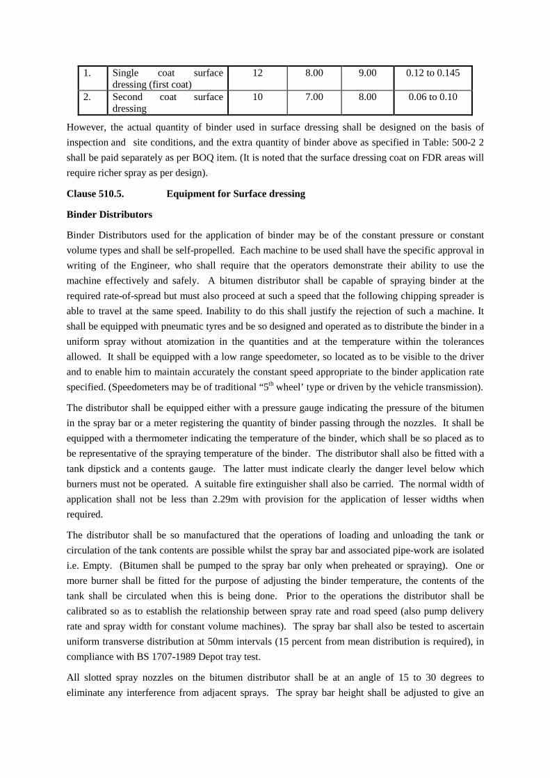
1. Single coat surface dressing (first coat)
12 8.00 9.00 0.12 to 0.145
2. Second coat surface dressing
10 7.00 8.00 0.06 to 0.10
However, the actual quantity of binder used in surface dressing shall be designed on the basis of inspection and site conditions, and the extra quantity of binder above as specified in Table: 500-2 2 shall be paid separately as per BOQ item. (It is noted that the surface dressing coat on FDR areas will require richer spray as per design).
Clause 510.5. Equipment for Surface dressing
Binder Distributors
Binder Distributors used for the application of binder may be of the constant pressure or constant volume types and shall be self-propelled. Each machine to be used shall have the specific approval in writing of the Engineer, who shall require that the operators demonstrate their ability to use the machine effectively and safely. A bitumen distributor shall be capable of spraying binder at the required rate-of-spread but must also proceed at such a speed that the following chipping spreader is able to travel at the same speed. Inability to do this shall justify the rejection of such a machine. It shall be equipped with pneumatic tyres and be so designed and operated as to distribute the binder in a uniform spray without atomization in the quantities and at the temperature within the tolerances allowed. It shall be equipped with a low range speedometer, so located as to be visible to the driver and to enable him to maintain accurately the constant speed appropriate to the binder application rate specified. (Speedometers may be of traditional “5th wheel’ type or driven by the vehicle transmission).
The distributor shall be equipped either with a pressure gauge indicating the pressure of the bitumen in the spray bar or a meter registering the quantity of binder passing through the nozzles. It shall be equipped with a thermometer indicating the temperature of the binder, which shall be so placed as to be representative of the spraying temperature of the binder. The distributor shall also be fitted with a tank dipstick and a contents gauge. The latter must indicate clearly the danger level below which burners must not be operated. A suitable fire extinguisher shall also be carried. The normal width of application shall not be less than 2.29m with provision for the application of lesser widths when required.
The distributor shall be so manufactured that the operations of loading and unloading the tank or circulation of the tank contents are possible whilst the spray bar and associated pipe-work are isolated i.e. Empty. (Bitumen shall be pumped to the spray bar only when preheated or spraying). One or more burner shall be fitted for the purpose of adjusting the binder temperature, the contents of the tank shall be circulated when this is being done. Prior to the operations the distributor shall be calibrated so as to establish the relationship between spray rate and road speed (also pump delivery rate and spray width for constant volume machines). The spray bar shall also be tested to ascertain uniform transverse distribution at 50mm intervals (15 percent from mean distribution is required), in compliance with BS 1707-1989 Depot tray test.
All slotted spray nozzles on the bitumen distributor shall be at an angle of 15 to 30 degrees to eliminate any interference from adjacent sprays. The spray bar height shall be adjusted to give an

exact single lap pattern i.e., each nozzle should spray to the centre of the adjacent nozzle. This must be checked in detail by shutting every second nozzle and seeing that the sprays just meet with no overlap. (Constant pressure distributors are frequently fitted with whirling spray jets). The distributors shall also be fitted with a hand-lance for spraying inaccessible areas.
At the conclusion of each spraying session e.g. when no further spraying is imminent, the spray bar and pump shall be cleared of binder, this shall be done by purging with air and also by flushing with solvent, if necessary. Additionally, operators shall maintain the spray bar and associated controls in a clean condition at all time. Filters shall be cleaned daily. These provisions are intended to ensure efficient working and easy start-up at each spraying session, they are clearly in a contractor’s own interest also.
The specification for a self-propelled bitumen distributor shall preferably be as per Appendix ‘D’(attached).
Chipping Spreaders (Gritters)
The spreading of cover aggregate (chippings) shall be done using chipping spreaders of suitable design. They shall be so constructed that the entire width of sprayed bitumen can be gritted in one pass following closely behind the bitumen distributor.
The Engineer shall ensure that supporting equipment items are adequate for the work intended, these shall include such items as bitumen decanters/heaters, pneumatic tyred rollers and mechanical brooms. Where cleaning is to be done manually, the Engineer shall require that workers with hand brooms (and other hand tools0 are provided in sufficient numbers that the main surface dressing operation is not delayed. This requirement extends also to remedial works (e.g. patching, pothole repairs and after-care work).
Synchronized Mechanical Binder Distributor and Chip Spreader
The contractor may use synchronized mechanical binder distributor and chip spreader mounted on a prime mover for surface dressing work instead of conventional system. The Engineer will approve the equipment prior to use.
Clause 510.6.Preparation of cutback grade bitumen for surface dressing at site.
The cut back grade bitumen shall be prepared under site condition in accordance with process as described in TRRL-Research Report 104 with little modifications. The summary of procedure is described below:
a) In most site operations the essential equipment will be a bitumen distributor, a bitumen decanter / heater and a small hand pump with a delivery hose capable of discharge into the distributor tank.
b) Calculate the volume of bitumen and diluent required based on the total volume of blend to be prepared. Prepare the diluent in suitable containers. (Note: If a kerosene / diesel blend is to be prepared e.g. for priming then calculate and measure out the individual quantities of both in separate containers.
c) Heat the bitumen in the decanter to the lowest temperature consistent with efficient pumping (for 80/100 pen grade this is approximately 140oC). If only diesel is to be blended in, however, in

relatively small quantities, say 6-8 percent then the temperature may be increased to 160oC. This shall not be permitted however if kerosene is to be included.
d) Extinguish all flames, cigarettes etc. and ensure that fire extinguishers are available. Remove all non-essentials and unauthorized persons front the work area. Essential personnel must wear protective clothing i.e. overalls, gloves, eye protections and boots.
e) Pump the hot bitumen from the decanter into the bitumen distributor but controlling the rate of loading such that diluent can be pumped into the distributor using the hand pump before the total blend volume has been attained. (The diluent delivery hose should dip below the level of the binder in the distributor at all times so as to avoid surface vaporization). (The addition method described ensures that diluent is initially well dispersed by the swirling action in the tank during loading). (If diesel and Kerosene to be added, add diesel first).
f) When the calculated quantities or bitumen and diluent have been loaded into the distributor, circulate the contents for approximately one hour to complete the mixing process.
g) It is inadvisable to pump diluent into a tank, which already contains a large volume of bitumen: the dispersion produced by e.g. a distributor pump is relatively slow, the procedure described in para (e): is preferred.
Bitumen grade 80/100 pen may be softened (“cut back”) using diesel fuel; whilst the actual consistency of any blend will depend upon the initial properties of the two components, Table 500-22A below may be used as a guide in preparing blends.
Table 500-22A
Preparation of Blends: 80/100-pen and diesel fuel
Road Surface Temperature (°C)
Binder Grade* Required (Approximately)
Diesel # (% Vol. Of Blend)
20-30 MC-3000 14 30-40 600-800 pen 11 40-50 400-500 pen 9 50-60 180-200 pen 4 60-70 80-100 pen Nil
*Based approximately on mid-point of road surface temperature range.
# Where 60/70 pen is used the percentage of diesel shall be increased by 1%
Diesel can conveniently be added to the distributor contents whilst the 80/100 pen. is being pumped in, thus assisting good mixing. The tank contents should then be circulated for at least one hour before spraying. No smoking or naked flames are permitted whilst blending is being done.
Clause 510.7. Spraying Temperature for binders
The spraying temperature for binders shall be as per given Table 500-22B below.
Table 500-22B
Spraying Temperatures for Binders
Cutback grades (US Asphalt institute)
Whirling Spray Jets Slot Jets Min °C Max°C Min°C Max°C

MC 30 50 60 40 50 RC/MC 70 65 80 55 70 RC/MC 250 95 115 80 90 RC/MC/800 115 135 105 115 RC/MC/3000 135 150 120 130 Penetration Grades 400/500 160 170 140 150 280/320 165 175 150 160 180/200 170 190 155 165 80/100 180 200 165 175
Note: Because of the inflammable nature of the solvent used in RC-type cutbacks, application temperatures for RC Grades should be restricted to the lower parts of the ranges given above.
Attention is also drawn to the need to extinguish flames and prohibit smoking when heating, pumping or spraying all cutbacks. Fire extinguishers should always be readily at hand.
Clause 510.8. Construction Operation
Clause 510.8.1. Weather and seasonal limitations:
Clause 501.5.1 shall apply.
Clause 510.8.2 . Preparation of Surface (Base)
The base on which the surface dressing is to be laid shall be prepared, shaped and conditioned to the specified lines, grade and cross-section in accordance with the clause 501 and as directed by the Engineer. The irregularities and surface damage such as potholes, depressions, ravelling shall be corrected prior to application of surface dressing. The Engineer shall also satisfy himself that fundamental defects e.g. base failure, drainage problems etc. have been remedied prior to commencement of surface dressing. All patches, however, occasioned, shall be thoroughly compacted, sealed and blinded with crusher dust before opening to traffic for several days before surface dressing commences. Priming coat, where needed shall be provided as per clause 502 and as directed by the Engineer.
Immediately prior to the application of binder, remove all dirt, dust or foreign material using brooming and / or the compressed air. Adhering mud or other soiling may be removed using water and brushes; the general use of water to wash the road shall not be permitted.
A fine graded wearing course shall be laid over the prepared surface(s) to fill excessive surface voids, wherever necessary or as directed by Engineer. The fine graded wearing course shall be 3mm in thickness. The grading and bitumen content for fine graded wearing course shall be as mentioned below in Table 500-22C below:
Table 500-22 C
Fine graded wearing course 3mm thick
Sieve (mm) Passing percentage by weight 6.3 100 3.35 85-100
600 µ 30-55

212 µ 14-32 75 µ 5-17
Binder content 3% ± 0.5% (using 80/100 or softer pen) by weight.
Clause 510.8.3. Safety and Maintenance
Bitumen heating, pumping and spraying operations shall be entrusted only to operatives who have been adequately trained such that they have a proper understanding of their equipment and are competent in its use. They shall ensure that unauthorized persons are not in the vicinity during the above operations. Operatives shall be provided with protective clothing, heatproof gloves, boots and goggles and shall be required to wear them.
At the end of each day’s work, any binder remaining in the distributor tank should be off-loaded to storage; the spray-bar, pipe-work and pump should be drained free of binder and then flushed with diesel or kerosene. The filter on the suction side of the pump must be cleaned daily.
Binder must be loaded into the distributor from suitable storage or decanters at a temperature some 5-10 degrees centigrade above spraying temperature in order to offset the cooling effect of the empty tank. The burners(s) fitted to the distributor shall be used to make only relatively small adjustments to binder temperature during the course of spraying operations. Burners MUST be extinguished before the distributor is allowed to move; burners must, moreover, not be operated unless the burner tubes (flues) are covered by at least a 150mm depth of binder.
The safety of construction workers and the general public must be ensured. If considered necessary the Engineer shall cause traffic to be diverted, using adequate signing, such as to exclude vehicles from the carriageway. The closure of an adequate width of road by the use of cones and barriers shall be considered to be minimum requirement. Flagmen shall be instructed clearly in their duties so as to provide safe traffic control.
Clause 510. 8.4. The surface dressing operation
The operation and pre-planning needed for surface dressing work shall be carried out meticulously by the contractor in consultation with the Engineer, preferably as described in Overseas Road Note 3 (TRRL) section 7.1 and 7.2.
To ensure that spray runs are parallel with the road pavement, the road centre line or edge line shall be marked every 25 meters and a string or chalk line provided so that the distributor driver can follow, using his guide bar. Spraying must not be attempted when the road surface temperature is below 10 degrees centigrade; the surface must be dry and clean. Before attempting to spray, the Engineer shall ensure that:
a) Traffic control measures are in place.
ii) All equipment and personnel are present and in the right place.
iii) Non-authorised persons and general public are excluded from the works.
iv) No traffic is allowed to pass whilst binder is being sprayed.

Before each spray-run, the spray-bar shall be circulated with hot binder and the jets opened to check for correct spray pattern. Suitable shallow tanks shall be provided for this purpose so as to conserve binder and prevent environmental damage. Where spraying is to continue from a previously treated length, protective metal sheets must be placed so that the jets are opened over them and that no soiling of the existing surface occurs. A similar precaution must be taken when spraying ceases at the beginning of a completed dressing such as jets are closed over the protective sheets. Where these constraints do not apply, the ends of sprayed lengths shall be trimmed to a straight edge, using hand tools. Sprayed lengths shall be restricted to those, which can be covered by the aggregate available in lorries. At the completion of each sprayed run, the distributor shall be directed to an off-road position to avoid dripping of binder on to the road. When defects in the sprayed binder film are observed e.g. due to blocked jets, spraying shall cease immediately and shall not be permitted to continue until the defective equipment has been rectified. Small-unsprayed areas can be treated using spray lance or hand can, as approved by the engineer.
The chipping spreader shall be operated such that it follows closely, (within 10m) behind the distributor. (This interval needs to be much reduced if using bitumen emulsion). The width covered by the spreader shall be such that on one side a strip of binder approximately 150mm wide remains un-gritted; this strip shall be over sprayed at the next pass so as to provide a neat joint. Operatives shall not be permitted to attempt the spraying of butt joints. Chippings shall, if considered necessary, be applied in a damp condition in order to prevent dust being deposited on the binder film provided that good drying conditions prevail. Additional chippings may be applied by hand if required. Aggregates shall not be broomed to promote even coverage.
The applied chippings shall be rolled using a pneumatic tyred roller of weight 10-12 tonnes and at a speed of approximately 8-10 km per hour so as to provide some 5 to 6 passes over the full width of the surface dressing. Depending upon the output achieved, a second similar roller may be required in order to complete the rolling operation. Steel-wheeled roller should be excluded from the work.
Clause 510.9. Double Surface Dressing
It is advisable to open the first dressing to traffic for at least 2 weeks before the second dressing is applied. This allows time for traffic to orientated chipping into a mosaic and the formation of a stable substrate for the second dressing; if any under or over-spray has occurred then this will be apparent and can be allowed for when designing the second dressing. Sprayed widths for the second dressing must be calculated such that over-spray joints are offset from those in the first dressing by approximately 300mm.
Clause 510.10. Opening to Traffic and After Care
No traffic shall be allowed over the new work before adhesion between binder and chippings has taken place. Prior to opening to traffic, any spillage of aggregate should be removed and any binder drips or wind blown contamination shall be dusted with crusher waste. After 2–3 days under traffic excess stones must be removed by brushing.
Clause 510.11 Surface Finish and quality control of works
The surface finish of construction shall conform to the requirement of Clause 902.

The Engineer shall exercise the Control on the quality of materials and works in accordance with the section 900.
For testing uniformity of transverse distribution of bitumen, the depot tray test as per BS 1707-1989 shall be carried out. (Test procedure as per Appendix ‘A’)
Clause 510.12. Arrangements for Traffic
During the period of construction, arrangement of traffic shall be done as per MORT&H Clause 112.
Clause 510.13 Measurement and Payments
The quantity of surface treatment to be paid for shall be measured in square metres and shall consist only of accepted work placed as directed by engineer or Specifications. Material, which has been placed elsewhere whether because of the requirements of the work or because of inadequate control, shall not be admitted as measured work.
The Contract Unit Price per square metre for the items shown on the Bill of Quantities, which payment shall be full compensation for furnishing all labour, materials, preparation of cut back, tools, equipment, laying fine graded wearing course and incidental items for performing all the work necessary in construction of surface dressing; completed according to the Specification.
The quantity of binder to be used in the work of surface dressing as per design, if exceeds the minimum specified in Clause 510.4, the same shall be paid in Kg. separately as per BOQ.
CLAUSE 516 SLURRY SEAL
Clause 516.1 Add paragraph 2 as under.
The work shall consist of mixing emulsified bitumen, well-graded fine aggregates (with mineral filler) and water, spreading the mixture and rolling on a pavement surfacing as a surface treatment. The work will also include taking out all loose bituminous\materials and refilling the same treating as pothole repair and filling wide gaps more than12mm wide, with Type A mix seal surfacing materials.
Clause 516.4.2Surface Preparation
Delete Para No. 1
Clause 516.4.3 Tack Coat
Amend the paragraph as under
Tack coat of rapid setting emulsion diluted with water as directed by the Engineer shall be applied on the road surface, prior to slurry seal at the rate of 0.15 to 0.3 litres / sqm for each of the two sprays of tack coat.
Clause 516.9 Rate
Add in end of para “tack coat, pot hole repair and filling wide gaps”.
Clause 518 Fog Spray
Clause 518.2 Replace first para as under:
“The bitumen emulsion shall be slow setting confirming to IS:8887”.

Clause 521 MODIFIED BINDERS
Clause 521.6 Measurement for Payment
Delete the first line of this sub-clause.
Clause 521.7 Rate
Delete this clause
SECTION 800 – TRAFFIC SIGNS, MARKINGS & OTHER ROAD APPURTENANC Clause 801 TRAFFIC SIGNS
Sub-Clause 801.1.2This clause shall read as under:
“All road signs shall be of retro reflectorized type and made of high intensity grade with encapsulated lens type reflective sheeting vide Clause 801.3, fixed over aluminium sheeting as per these specification”.
Clause 801.4 Installation
Clause 801.4.1Third sentence shall be replaced as under:
The support post for the signboard shall be MS angle iron / T-section along with angle iron back frame for support of the signboard. Details of post shall be as under:-
Type of Sign Board No. of Posts Height
Size of angle for back frame and main post Main Post Back Frame
Caution / Warning sign, mandatory 1 3.7 m
75x75x8mm angle iron or T-section
25x25x3mm angle iron
Information sign: facility information and route marker 1 3.7 m
75x75x8mm angle iron or T-section
25x25x3mm angle iron
Information signs such as advance directions/destination/Reassurance board
2 4m 75x75x8mm angle iron or T-section
45x45x6mm angle iron
Fastener shall be zinc-plated bolts and nuts for fixing retro reflective sign board to the post. The board shall be suitable for 12mm hole. The size of the bolts shall be 10 mm dia x 30mm with nut and spring washer.
Clause 803 ROAD MARKINGS
Clause 803.2 Materials
Substitute this section as under:
“Road markings shall be of hot applied thermoplastic compound and the material shall meet the requirements as specified below.”
Sub-Clause 803.3.2 This Clause shall read as under:

“The road markings shall be laid mechanically with appropriate road marking machinery as approved by the Engineer.”
Sub-Clause 803.6.3The last sentence of the third paragraph shall read as under:
“The glass beads shall be applied at the rate of not less than 400 grams per square meter area.”
Clause 805 ROAD DELINEATORS
Sub-Clause 805.2 Add the following after the first paragraph:
“Road delineator posts shall be in reinforced cement concrete and the reflectors attached to both sides as shown on the drawing. Reflectors shall be in accordance with IRC 79-1981. Reflectors shall be firmly fixed to the RCC post by a method, which discourages theft and is approved by the Engineer.
Add a new clause
Clause 812 Guard Stones/ Indicator stones
Clause 812.1 General
The work comprises of supplying and fixing guard stones/ Indicator stones as per drawing and at locations as directed by the Engineer. The work shall cover supply and fixing of guard/indicator stones made of M20 grade Cement concrete of shape and size as given in the contract drawing and painting two or more coats to give even shade with superior grade enamel paint. The guard/indicator stones shall be bedded in the ground with adequate concrete foundations as shown in the drawing.
Clause 812.2 Measurements for Paymen
The measurements shall be made in numbers of guard/indicator stones fixed at site.
Clause 812.3 Rate
The contract unit rate for guard/indicator stones shall be payment in full compensation for furnishing all labour, materials, tools, equipment for preparing, supplying & fixing and all other incidental costs necessary to complete the work to these specifications.
TRAFFIC SAMPLING R&BD, GoG through independent consultant shall have the right to undertake traffic sampling for the purpose of determination and/ or verification of the actual traffic on the projecthighway.Thisshallbedonethroughautomaticcountingofvariouscategoriesof vehicles separately as indicated in Schedule-W. The sampling shall be done at intervals of 15daysby continuous24 hrs counting for three days. If no abnormal trends are observed in three days counting at the frequency of 15 days, the frequency would be increased to 1 month after a period of one year. Apart from theseperiodicalcounts,theIndependentConsultantshallhavetherightfor traffic counting at a request from the R&BD, GoG. The traffic count as obtained from the samples shall be taken as actual traffic on the project Highway at the locations of the counting. TECHNICAL REQUIRMENTS All equipment shall have built-in or have complete protection devices. ATCC SYSTEM

The Automatic Traffic Counting & Classification system is to be installed, commissioned, operated and maintained for Concession Period on 4 lane sections of the Dabhoi – Bodeli road at minimum 2 (two) identified locations at km. 32+500 and Km. 58+700 with the objective of carrying out traffic study and survey to enable the Road and Buildings Department, GoG collect vehicle count data by classes. GENERAL REQUIREMENT a) The ATCC system shall classify the vehicles as defined in IRC:3-1983 and IRC:9-1972. Calibration of the instruments /system shall be done in consultation with the Independent Consultant and the Employer. Slow moving/under sized vehicles which may not be able to be identified by the ATCCs due to limitation of technology shall be counted & classified manually for seven days at each location and shall be included in the traffic data being reported. The concessionaire under discussion with the Independent Consultant and the Employer shall plan such manual counts. The approval of the Independent Consultant and the Employer shall be obtained in writing before starting manual count and including it in the traffic data at GoG’s Central Data Center’s. In case of a long term count station, if the slow moving vehicle is to be counted manually due to limitations of the technology, it should be carried out at least for consecutive 7days (24 hrs. continuously) every month. b) This information of nos. of categorized vehicle shall be stored in a secured database and further transmitted to the GoG’s central data centers(CDC) by using any of the available communication mode at site like GSM (Global System for Mobile Communications) / GPRS(General Packet Radio Service), landline modem, CDMA (Code Division Multiple Access) or any other links depending upon the effective and economic operation of the particular mode available at the site. c) The system should be able to work as true Multi-lane free flow operation in which the Lane crossing classification should be possible together with simultaneous passages. The system should be capable of recognizing the flow of traffic in either direction. d) Vehicles that change the lanes while passing across the ATCCs, shall be detected and classified as accurate as vehicles. e) Vehicles passing at the same time – side by side shall be separately detected and classified. f) Trailers with the shafts shall be detected and classified as one vehicle and not classified and counted as separate vehicles. g) The system shall be electric/ solar power operated depending upon the availability of source. h) The design and installation of ATCCs should be such that no manpower shall be required at ATCC locations. However, personnel for its security etc. shall be provided by the concessionaire aspart of this work. TECHNICAL REQUIREMENT Performance Requirement The system shall be capable of the following performance criteria: (i) Counting the traffic to an accuracy of more than 95% of actual traffic. (ii) Classifying traffic to the specified classes with the accuracy of more than 95%. (iii) Operating speed of vehicles shall be of up to 160 kmph. (iv) Operating temperature shall be -10o C to +55 o C (v) Sufficient standalone storage for each device for 15 days of traffic data. (vi) Each ATCC should have a unique local address that shall allow for remote access. (vii)The software shall enable full remote and local status monitoring of the following functions. (a) Power status (b) Sensor status

(c) Memory status (viii) The system shall be capable of operating using mains as well as battery power. Batteries shall have sufficient capacity to operate the system for a period of not less than 7 days without recharging .Batteries shall be fitted with a solar recharging device that enable the batteries to support the system indefinitely in average daylight conditions. (ix) The Road-side unit shall be lockable stainless steel cabinet and shall comply with IP 65 standards. ATCC Reporting Requirements It is a requirement that the ATCC system shall be capable of providing data and reports on a regular, usually hourly, daily and weekly basis, by remote log in by the Independent Consultant / Roads and Buildings Department. The ATCC and CDC system shall be capable of collecting real time traffic data, data storage in a secured database, immediate data transmission from ATCC to CDC by suitable / reliable latest technology viz GSM (Global System for Mobile Communications) /GPRS (General Packet Radio Service), landline modem, CDMA(Code Division Multiple Access) or any other links, available at the location. The ATCC system shall validate process, store and transfer the processed data at least every hour. The design and structure of the data base shall be submitted to the Independent Consultant and Roads and Buildings Department for approval prior to the final development and deployment thereof. In case there is no communication link available at the location, the seven day data shall be transmitted to CDC within 48 hours of completing the seven day count on optical media like DVD or CD. The Traffic data generated shall be available for incorporation in theGIS based Information System being developed by Roads and Buildings Department. The reporting shall consist of the following: (i) Position and status of the ATCC and in the event of failures the time of the failures. (ii) Hourly traffic reports by number, class and direction of vehicles. (iii) Daily/ weekly/ monthly / quarterly / annual summary of the above hourly reports.
SECTION 900 – QUALITY CONTROL FOR ROAD WORKS
Clause 901.10
Amend the clause 901.10 as under:
For bitumen/cutback/emulsion, mild steel, cement and other similar materials where essential tests are to be carried out at the manufacturer’s plants or at laboratories other than the site laboratory, the cost of samples, sampling, testing, and furnishing of the test certificates shall be borne by the Contractor. The frequency of test regarding bitumen, cutback and emulsion in respect of its quality shall be as per the Table 900-4 of MORT&H Specifications.
Clause 902 Control of Alignment, level and Surface regularity
Sub-Clause 902.4 Surface Regularity of Pavement Courses
Add the following at the end of this sub-clause:

“In addition to the straight-edge test the ride ability of the finished wearing course, when tested with a fifth-wheel bump integrator shall have a surface roughness of no more than 2000mm/Km.”
Clause 903 QUALITY CONTROL TESTS DURING CONSTRUCTION
Sub-Clause 903.4 Tests on Bituminous Constructions
Clause 903.4.2 Acceptance Criteria
Table No. 900-4 Control tests and their minimum frequency for Bituminous works. Substitute item of density of compacted layer as under
Sl.No Type of Construction Test Frequency (minimum)
4 (xiii) Bituminous Macadam for PCC and Overlay
(xiii) Density of Compacted layer Core cutting and testing for thickness and density.
One test per 1000 m2 area.
6(xviii) Dense Bituminous Macadam and Bituminous Concrete
(xiii) Density of Compacted layer Core cutting and testing for thickness and density.
One test per 1000 m2 area. 10% of the density tests shall be done on edges at locations desired by the Engineer.
SECTION 1000 – MATERIALS FOR STRUCTURES
Clause 1006 CEMENT
The first paragraph of this clause shall read as under:
“Cement to be used in the works shall be any of the following types with the prior approval of the Engineer.”
a) Ordinary Portland cement, 33 Grade, confirming to IS: 269. b) Ordinary Portland Cement, 43 Grade, confirming to IS: 8112.” c) Ordinary Portland Cement, 53 Grade, confirming to IS: 12269.” Delete paragraph 4 and 5 from Clause 1006.
CLAUSE 1009 STEEL
Clause 1009.3 Reinforcement/Untensioned Steel
In Table 1000-3, Item in column No. 2 against S 415 may be read as:
“IS: 1786 (amended) High yield strength TMT bars (Grade designation - TMT)”.
Clause 1010 WATER
In paragraph (c) ‘the Permissible Limits (max) for Chlorides (Cl)’ shall be read as “500 mg/lit”. Delete the asterisk * footnote furnished at the end of Sub-Clause.
Clause 1014 STORAGE OF MATERIALS
Sub-Clause 1014.3 Aggregates

The following shall be added at the end of this Clause:
“Aggregates shall be stockpiled in a manner that will avoid segregation, contamination by foreign materials and intermixing of various sizes of aggregate”.
SECTION 1300 – BRICK MASONRY
Clause 1308 Jointing old and new work
Add the following as the fourth paragraph.
In case of fresh masonry (abutments/pair) is to join with old masonry a cutting is made in the old masonry to the size of 200mm x 200mm x 200mm. While joining the new masonry a pre-cast key in concrete grade M20 of size 200mm x 200mm x 400m is inserted and interstices filled with M20 Concrete or Cement Mortar 1:4 into the opening already cut so that half portion of the key is embedded in the old masonry to depth of 200mm as a bonding member. The rest of 200mm will be in built in the new masonry. The keys shall be spaced vertically at distance of 1000mm staggered.
SECTION 1500 – FORMWORK
Clause 1509 RE-USE OF FORMWORK
Add the following sentence at the end of paragraph 2 of this Clause:
“After cleaning and rectification and before refixing, form work shall be approved by the Engineer”.
SECTION 1700 – STRUCTURAL CONCRETE
Concrete Grade Current Margin (M Pa) Target Mean Strength M10 7 17
Clause 1703 GRADES OF CONCRETE
Sub-Clause 1703.1 Add the following to Table 1700-1.
Grade Designation Specified characteristic compressive strength of 150mm cubes at 28 days, in MPa.
M10 10 Sub-Clause 1703.2 Add the following to Table (B).
(B) MINIMUM STRENGTH OF CONCRETE
Member Conditions of Exposure Moderate Severe
d) Filling material M10 M15 Sub-Clause 1704.2.1 Target Mean Strength
Add the following to Table 1700-5.
Concrete Grade Current Margin (M Pa) Target Mean Strength M10 7 17
Sub-Clause 1704.3 Requirement of Nominal Mix Concrete
Add the following to Table 1700-6.

Table 1700-6
Concrete Grade Total Quantity of dry aggregate by mass per 50 kg of cement to be taken as the sum of individual masses
of fine and coarse aggregates (kg)
Proportion of fine to Coarse aggregate
(by mass) M10 480 1:2
Clause 1706 SIZE OF COARSE AGGREGATE
Substitute first sentence of this Clause as under:
“The size (maximum nominal) of coarse aggregates shall be 20 mm or smaller for reinforced cement concrete and 40 mm for plain cement concrete”.
Delete ‘TABLE 1700-7’.
SECTION 2000 – BEARINGS
Clause 2009 MEASUREMENTS FOR PAYMENT
Add the following after paragraph 2 of this Clause:
“Paper bearings shall be measured in square meters”.
SECTION 2500 – RIVER TRAINING WORK AND PROTECTION WORK
CLAUSE 2503 APRON
SUB-CLAUSE 2503.3 LAYING WIRE CRATES AND MATTRESSES IN THE APRON
Delete this clause and replace with:
The wire crates shall be made from hot dipped galvanised mild steel wire complying with IS280 in the diameters (in annealed condition) mentioned in the table No. II, having a minimum tensile strength of 300 MPa. The weight of deposition of the zinc shall be minimum 260 gram per square meter for the gauge of wire specified. The wire shall be mechanically woven into a hexagonal mesh with a minimum of three twists. All edges of crates shall be finished with an annealed selvedge wire at least three gauges heavier than the mesh wire. Diaphragms shall be manufactured of the same material as the parent gabion and have selvedge wire through out their perimeter. Gabions and gabion mattress sizes are furnished in Table1. Wire mesh, wire sizes (binding connecting) are furnished in Table II. All filling for gabions shall be with hard angular stones. The smallest dimension of any stone shall be at least twice that of the longer dimension of the mesh of the crate.
Gabions or Gabion Mattresses shall be assembled by binding the edges together at selvedges with binding wire. The binding shall be in the form of continued lacing so that the interval between the laces is approximately 50 mm. The crates shall be stretched to their full dimensions placed and pegged to the ground or wired to the adjacent gabions before filling. The diaphragms shall be laced into position at the time of assembly leaving the lids of the crates open. . Before filling commences selvedges of the crates will be bound to the selvedge wire of the next crate. The vertical corners of

the boxes shall be kept square by inserting a 20mm dia bar at each vertical corner, and shall be kept in that position throughout the filing process and shall be removed when the crates are full. The filling shall be in layers by hand in courses. The filling will be carried out by placing individual stones into the gabion by hand in courses in such a manner that the stones are bedded on each other and bonded as in dry random rubble masonry. No loose stones shall be tipped into the crate and the practice of coursing and bonding the outer layer and filling the interior with unlaid stones will not be permitted. When the crates are full the lids will be closed and the selvedges bound with binding wire as in the assembly process.
1. Table I: STANDARD SIZE OF WIRE MESH GABIONS
Sr. No.
Dimensions in meters
Number of Diaphragms
Dimensions of Diaphragms in meters
Volume of crate cubic meters
Nature
2 x 1 x 1 1 1 x 1 2 Gabions 3 x 1 x 1 2 1 x 1 3 Gabions 4 x 1 x 1 3 1 x 1 4 Gabions 2 x 1 x 0.5 1 1 x 0.5 1 Mattresses 3 x 1 x 0.5 2 1 x 0.5 1.5 Mattresses 4 x 1 x 0.5 3 1 x 0.5 2 Mattresses 2 x 1 x 0.3 1 1 x 0.3 0.6 Mattresses 3 x 1 x 0.3 2 1 x 0.3 0.9 Mattresses 4 x 1 x 0.3 3 1 x 0.3 1.2 Mattresses
2. Table II. STANDARD SIZE OF WIRE MESH GABIONS
Sr.No.
Dimensions in
mm
Thickness of mesh wire
Thickness of binding and connecting wire
Thickness of selvedge wire
S.W.G. MM S.W.G MM S.W.G MM 50 x 70 12 2.64 13 2.34 9 3.66 60 x 80 12 2.64 13 2.34 9 3.66 60 x 80 11 2.95 13 2.34 8 4.06 80 x 100 11 2.95 13 2.34 8 4.06 80 x 100 10 3.25 12 2.64 7 4.47 80 x 100 9 3.66 11 2.95 6 4.88 100 x 120 10 3.25 12 2.64 7 4.47 100 x 120 9 3.66 11 2.95 6 4.88
Clause 2504 Pitching/Revetment on slopes
Replace by the following:
The pitching shall be provided as indicated in the drawings. The thickness and the shape of Cement Concrete block pitching shall be as shown on the drawing.
Sub-Clause 2504.2.1 Pitching
Cement concrete blocks in M15 grade conforming to Section 1700 shall be used for pitching. Use of geosynthetics has been dealt in Section 700
Sub-Clause 2504.2.2 Add the following at the end of this sub clause
Light weight N series polypropylene Geo textile fabric as approved by the Engineer..

This nonwoven filter membrane is placed underneath the pitching or the gabion boxes/mattresses on the bed of slopes in lieu of the graded filter materials. It is a highly permeable filter membrane and prevents the escape of fines, allows free water movement without creating any uplift head on the pitched surface. The surface on which this fabric is to be laid is to be trimmed to the required slope and the filter fabric spread over the surface. When they are connected they should have an overlap of 300mm to ensure proper continuity.
Clause 2509 Measurement for Payment
Add this paragraph at the end of this sub clause: The contact unit rate for the Geo textile filter membrane shall be in square meters for the covered area.
CLAUSE 2510 RATE
Add this paragraph at the end of this sub clause:
The contract unit rate for one cubic meter of Gabions and Gabion mattresses furnished include the cost of all materials, stones) including leads and lefts, labour tools and plant for completing the work in accordance with the above specifications.
SECTION 2700 – WEARING COAT AND APPURTENANCES
Clause 2702 Wearing Coat
Sub-Clause 2702.1.1 Item (II) of this Clause shall read as under
“50mm thick Asphalt wearing coat in one layer as per Clause 509”.
Clause 2706 WEEP HOLES
Add the following after the first paragraph.
A porous concrete block measuring 250mm x 250mm x 100mm made with “no fines” concrete is to be placed over the inlet to the weep hole. The concrete mix is to be 1 part of cement to 4 parts of course aggregate (5mm to 10mm).
Clause 2708 MEASUREMENT FOR PAYMENT
Item in item (V), in the first sentence substitute “in numbers” by “in linear meters.
Clause 2709 RATE
Add in the last in the first paragraph of this Clause.
“The rate shall cover 5% bitumen content in asphaltic concrete and 14 to 17% in mastic asphalt. The adjustment in rate shall be made when there is variation in bitumen content”.
SECTION 2900 – PIPE CULVERTS
Clause 2904 BEDDING OF PIPE

Delete the last two sentences of the first paragraph and substitute with
“The bedding material shall be well graded granular material passing through 22.4mm sieve and retained on 5.6mm sieve suitably compacted/rammed. The compacted thickness of the bedding layers shall be as shown on the drawings and no case shall be less than 75mm.
“Aggregates shall be stockpiled in a manner that will avoid segregation, contamination by foreign materials and intermixing of various sizes of aggregate”.
SECTION 3000 MAINTENANCE OF ROAD
CLAUSE 3004 BITUMINOUS WORK IN CONNECTION WITH MAINTENANCE AND REPAIRS
Clause 3004.2. Filling Potholes and patch repairs
Clause 3004.2.1. Scope
Amend this clause as under
This work shall include repair of potholes and patching of all types of bituminous pavement. The minimum area and depth for a pothole shall be 25 sqcm and 1 cm respectively.
“The areas to be patched/repaired shall be located by the Engineer. They shall be cut/trimmed either with jack hammer or hand tools like chisels, pick-axes etc., such that the areas are in the shape of rectangles or squares. The edges shall be cut vertically up to the level where the lower layer is suitable without any loose material. The areas shall be thoroughly cleaned with compressed air or any appropriate method approved by the Engineer to remove all dust and loose particles. The excavations shall then be filled with material as mentioned hereunder. Each layer shall be compacted with approved mechanical tampers/small vibratory roller and the top layer shall be flush with the existing bituminous surface. All loose and/or surplus materials on the surface shall be removed, for potholes.
Deep Potholes (Depth of which is more than 75mm)
The excavation shall be filled up with wet mix macadam mix material (as per clause 406) each layer not exceeding 150mm in thickness duly compacted up to the existing crust thickness less 20 mm. The prime coat and tack coat as per MORT&H Clause 502 and 503 shall be applied over the top of the horizontal surface of repaired pot hole and vertical side surfaces shall be painted with the thin layer of hot straight run bitumen /emulsion. The top 20mm portion above the repaired pothole shall be filled up by Type B MSS material as approved by the Engineer and duly compacted.
Shallow potholes (Depth of which is less than 75mm)
The excavation shall be filled up with Bituminous macadam material as approved by the engineer in layer duly compacted. The finished surface of repaired pothole shall be up to the top of existing bituminous pavement. The tack coat as per MORT&H Clause 503 shall be applied over the top of the horizontal surface of excavated area and vertical side surfaces shall be painted with the thin layer of hot straight run bitumen /emulsion.
Clause 3004.2.2 Materials
Delete Paragraph 1 and 2 and substitute as under;

“All materials used for the pothole and patch repair of bituminous surface and underlying layers shall be in accordance with this specification and shall of the same type as specified in clause 3004.2.1. An emulsified bitumen / modified bitumen mix compatible with the existing layer shall also be considered appropriate for top surfacing of deep pothole or for complete shallow pothole.”
“The bituminous mixture used for such patch repairs shall be in accordance with the appropriate clause of these specifications.”
Clause 3004.2.5 Measurement for Payment
Amend this clause as “Filling of deep and shallow potholes and patch repair shall be measured in sq.m.
Add Clause 3006
CLAUSE 3006 CLEANING OF DRAINS
Clause 3006.1 Scope
The work of cleaning of drains shall include removal of earth, muck, rubbish, organic and inorganic materials from the earthen or Pucca drain including their disposal, de-watering and making temporary diversions of water etc. The drains shall be repaired if required which includes repairs to lining, beds; pointing & plastering with Cement mortar 1:3. The covered drains shall be cleaned after removing the cover and replacing the same after completion of cleaning operations.
Clause 3006.2 Material
The material to be used for repair shall be in accordance with Clause 1000.
Clause 3006.3 Procedure
The work shall be carried out manually or by machine as per directions of Engineer. The work shall be carried in such a manner that the existing structure of the drain does not get damaged. The contractor shall be fully responsible to make good the damages caused while cleaning operations as per direction of Engineer. In case Extra earth is needed for providing proper bed slope or side walls, the same shall deemed to be included under the cleaning operations as this is incidental to work. For covered drains the cover shall be removed carefully and replaced after the operation of cleaning is completed.
Clause 3006.4 Measurements for Payment.
Cleaning of drains shall be measured in running meters irrespective of cross sectional area. The earthen drains and Pucca drains shall be measured separately and paid under relevant item of BOQ.
Clause 3006.5 Rate
The contract unit rate of cleaning drains shall be payment in full compensation for
(i). Cleaning & removal of earth, muck, rubbish, organic & inorganic materials and disposal of the same within a lead of 1 Km.
(ii). De-watering, making temporary diversion of water for cleaning operations.
(iii). Repair to lining of drain in beds, side walls including plastering & pointing with CM 1:3 where

necessary.
(iv). The extra earth needed for providing proper bed slopes or repairs to side slopes for earthen drains.
(v). Removal and re-fixing the cover of drains in case of Covered Pucca drains.
(vi). All tools, equipment, manpower, materials and incidentals to complete the work in accordance with the above specifications
SECTION 3100 REINFORCED EARTH STRUCTURES CLAUSE 3101 (a) Scope of works All elements comprising the reinforced wall such as the facia units, the reinforcement with accessories/fittings and the select backfill material shall all be laid in conformity with the specifications and in compliance with the lines, grades, design and dimensions as per the approved drawings.
The reinforced soil structures shall be designed for a service life of 100 years. The warranty period of the reinforced soil structures shall be twenty years from the date of completion of flyover. For the reinforced soil structures the contractor (s) shall furnish the performance warranty bond for a minimum period of twenty years and a professional indemnity cover for five years as directed by the Engineer. The defect liability period for the reinforced soil structures shall be one year. The work shall be done in conformity with the MORTH specifications for Road and Bridge works, Reprint 2002, Section 3100. Detailed design and drawings shall be executed in accordance with MORT&H specifications and as per the provisions of the BS 8006-1995 “Strengthened/Reinforced soils and other fills” meeting the ultimate and serviceability limit state requirements. For external and internal stability analysis under seismic loading French Standard NF 94-220 and AASHTO/ US Federal Highway Administration (FHWA) design guidelines (FHWA-NHI-00-043) shall be followed.
Traffic live loads, traffic impact loads on vehicle safety barrier system shall be taken in accordance with the design requirements and earthquake loads as per IS: 1893-2002.
Reinforced soil being a specialized technology, the contractor shall furnish design approval by the engineer and make his own arrangements to secure the supplies and services needed. The past experiences and credentials in details of the specialized agency executing the reinforced wall construction shall be submitted well in advance for the approval of the Engineer. The reinforced soil structure technology shall have a proved adoption with regard to durability. The approved agency shall furnish documentary proof of satisfactory performance of their proposed methodology for at least 10 years. The approved executing agency shall have successfully completed at least one project of construction of reinforced soil structures of height not less than 10.0m and a total of minimum 30,000 square meter of reinforced soil structures in India. He should provide authenticated details of licensing and collaboration arrangement, where relevant for prior approval.
Working drawings and design calculations shall be submitted to the Engineer for review and approval at least five weeks before the commencement of actual construction work. These shall include the following: i. Existing ground levels that have been verified by the contractor for each location involving the
construction wholly or partially in the original ground. ii. Layout of walls, design calculations and drawings, material specifications and construction
methodology including quality control and quality assurance of different components. iii. Earthwork requirements including detail sub-soil investigation report, specifications for

materials and compaction of fill. iv. Details of drainage systems and any other facilities. v. Test results of soil reinforcing structural element from manufacturers/ suppliers. vi. Test results of various materials from a reputed independent laboratory in India. vii. Any other information required in the plans or special provisions or requested by the Engineer.
CLAUSE 3102 REINFORCED EARTH BACKFILL The reinforced fill shall be a select granular fill having high frictional resistance, low compressibility and free draining. Coarse-grained soils with limited fines adequately satisfy these requirements. Thus, the select granular fill may contain fines content (passing 75 micron sieve) not exceeding 10%. In extreme case, materials with less than 20% passing 75 microns can be acceptable with the approval of Engineer provided the internal friction angle is not smaller than 300. Co-efficient of uniformity (Cu) of the backfill shall be greater than equal to 5 barring extreme case for which Cu should be greater than 3.
The fill shall also be free from organic or otherwise deleterious materials so as not to cause corrosion of the soil reinforcement and the facia panels. It shall conform to the following physicochemical requirements.
Fill material shall have a resistivity of 5000 ohm-cm or more determined based on standard test as directed by Engineer and materials with resistivity less than 1000 ohm-cm are inadequate and shall not be used. Materials with resistivity between 5000 & 1000 ohm-cm are acceptable provided that in water extracted from soil-water mix, the content of chlorides does not exceed 200 ppm, the content of Sulphate does not exceed 1000 ppm, and the pH value is in the range of >5<10. The foundation soil’s electrochemical requirements should also meet the above criteria. If not, special consideration will be given to the design of reinforcing strips and facing panels. Good drainage characteristic of the select fill shall be maintained all through the design life of the RE wall including guarding the fill against the effect of “Chance” water logging of the facility. The select fill shall be compacted to ensure achieving peak angle of friction not lower than 30° as established from the direct shear test (IS 2720 Pt.13). For design, effective cohesion of fill shall be taken as zero.
The compacted layer should not be more than 200mm thick. The compaction of backfill material shall be 98% of maximum laboratory density obtained from modified proctor compaction test performed as per IS 2720 (Pt-8) or minimum 80% relative density for one metre depth below the road crust and minimum 95% of maximum laboratory density measured as per IS: 2720 (Pt-8) or minimum 75% relative density for remaining portion of fill materials.
Water used for compaction of the select fill should have minimum resistivity exceeding 700 ohm-cm.
CLAUSE 3103 QUALITY CONTROL For every 300 cum of fill material or whenever the approved source is changed, one sieve analysis, one measurement of resistivity, angle of internal friction and modified Proctor/ relative density shall be carried out. Any further tests on soil to confirm its suitability as “reinforced earth backfill” can be decided based on the results of these tests. However, organic and deleterious content,pH, sulphate and chloride content shall be carried out as decided by Engineer. CLAUSE 3104 REINFORCING ELEMENTS Either of the reinforcing materials such as high adherence steel or polymeric geogrids may be used for reinforcing the select fill. The reinforcement may take the form of strips, grids, sheets, anchors etc.

However, selection of a suitable reinforcing element can be done as per specifications given by MORTH (ref. cl. 3102-2002). All metallic components buried in soil shall be made of electrolytically compatible materials. Where this is not possible, effective electrical insulation of durability equal to the service life of the structure shall be provided between different materials. Shapes and dimensions of these elements shall be as shown on the approved drawings. The minimum width of the individual steel strip must be 40mm and minimum thickness must be 5 mm. Tie strips and High Adherence Reinforcing (HAR) steel strips shall be hot rolled. Their physical and mechanical properties shall conform to European norms BSEN 10025. Tie strips shall be fabricated from the plain strips of 40 x 4mm with same specification as of reinforcing strips. Reinforcing and tie strips shall be cut to the lengths and tolerances shown on approved drawings. Holes for bolts shall be punched in the locations shown. They shall be carefully inspected to ensure they are true to size and free from defects that may impair their strength or durability. Bolts and nuts shall be hexagonal in shape and high strength screw conforming to European norms BSEN 24014 or BS 3692 CLASS 10.9 or equivalent IS. They shall be 12mm in diameter 40mm in length with shank, hot dip galvanized conforming to BS 729 or ASTM A153 or equivalent IS. Corrosion allowance (sacrificial thickness) for galvanized steel exposed to various environments shall be as follows (as per French Standard NF A05-252): (i) Minimum life service of RE wall = 100 years (ii) Reinforcement Material i.e. A.G. grade i.e. hot dip galvanized steel – 500 g/m2 of zinc coating per face, 1.5mm thick for the dry site conditions & 2.0mm thick for the immersed site conditions. The manufacturer shall provide the test results of all physical and mechanical properties of metallic reinforcement for each lot or as required by Engineer. The geogrid shall be made from high molecular weight and high tenacity polyester (PET) yarn or high-density polyethylene (HDPE). Materials should be confirming to BIS, ISO 9002, BBA or FHWA. The PET geogrids should satisfy the following electrochemical conditions: • Minimum molecular weight no. > 25000 • Maximum carboxyl end group no. (CEG) < 30 • Minimum mass per unit area (ASTM D 5261)> 270 g/ sqm Polyester geogrids shall be quoted with a protective PVC coating to maximize the resistance to hydrolysis and enhance durability during construction and in service. Geogrid shall be produced by weaving/ knitting process to ensure junction strength. High-density polyethylene geogrids shall be manufactured by extruded, drawn sheets and by punched and orientation process in one direction so that the resulting ribs shall have a high degree of molecular orientation, which is continued through the integral transverse bar. It shall contain adequate stabilisers to enhance stability to environmental stress cracking (ESC), photo oxidation (UV exposure) and thermal oxidation. Materials should be confirming to ISO 9002, BSA, and FHWA etc. The maximum allowable design load of the geogrid type shall be higher than the required tensile load defined by the stability analysis in the Design of the wall structure. The manufacturers of geosynthetic materials must be able to supply creep test data/results for the period of minimum 10 years over a temperature of 40deg C minimum (Facing temperature attained in most tropical Indian climates/locations where geosynthetics is connected to the modular block wall facing). The post

construction strains in geosynthetics must be restricted below 0.5% for approach highway retaining walls and for abutments (mixed or pure type) to meet serviceability state requirements. The manufacturer/supplier of geosynthetic material must conduct site specific test to assess the potential for construction damage and strength loss in geosynthetic based on the quality of backfill soil, compaction equipment and efforts utilised and type of geosynthetic proposed for use. The same shall be accounted in the design as partial factor of safety from construction/installation damages.
Specific chemical compatibility tests to account for adverse effects of pH, chemicals, aqueous solutions of salts, acids and alkalis etc. at soil/fill ambient temperatures of 40deg C (facing temperature) for site specific backfill soils shall be assessed and accounted to the design as partial factor of safety from chemical degradation on geo-synthetics. In Indian conditions, geo-synthetics may be subject to strength loss and damage of its structural integrity from burrowing animals/organisms like rats, which may use them as food and nutrition value, in spite of the polymers inertness to support biological activity. Such factors must be accounted as material factor of safety from biological degradation. Special measures must be adopted to ensure that risk from fire hazards and thereby release of toxic fumes are eliminated and the same be accounted for in the detailed proposal for ensuring structural integrity ofthe construction. The manufacturer/supplier of the geo-synthetic - precast concrete facing system must conduct test results to sustainable the choice of interaction properties (direct sliding and bond coefficients) with site-specific backfill materials in design calculations. In no cases such interaction coefficients more than 0.9 and 0.8 respectively be used in the design for the backfill properties specified in this documents in accordance to International/National standards. All quantity control strength of geo-synthetics must represent minimum average roll values (MARV) only corresponding to 95% confidence limit. Testing of geo-synthetic for tensile strength shall be performed for every 5000 m2 and test data for each lot of material shall accompany shipments. Samples of reinforcement elements to be used for the project shall be submitted along with documentation notarized by the manufacturer that the material meets the project specifications. Approval of the material by the Engineer shall be required prior to delivery of the material to site. One complete set of property testing shall be carried out at a reputed independent laboratory in India as approved by Engineer for each lot. The testing shall preferably be performed on the lot, which was tested for quality control purpose at manufacturer’s laboratory or as decided by Engineer. The coefficient of friction between the reinforcing element and the select fill shall be determined from the results of modified shear box tests. Following minimum Partial factor of Safety for calculation of 100 year long term design strength (LTDS) shall be applied in accordance with the provisions of BS-8006: 1995 taking into account effects of various types of damages and inconsistencies.
Minimum partial FOS for calculation of 100 years long term design strength (TD) in
accordance with BS 8006:1995 requirement
HDPE based
geogrids
PET. Based geogrids
Woven PP based
geotextiles
Woven PET
based geotextile
1. Partial FOS for creep deformation (at 40°C to meet less than 0.5% post construction strain requirement for retaining wall cases)(Tu/Tcs)
5.5 2.75 6.0 3.0
2. Partial FOS for variations in manufacture 1.0 (use A1.00 (use 1.0 (use 1.0 (use
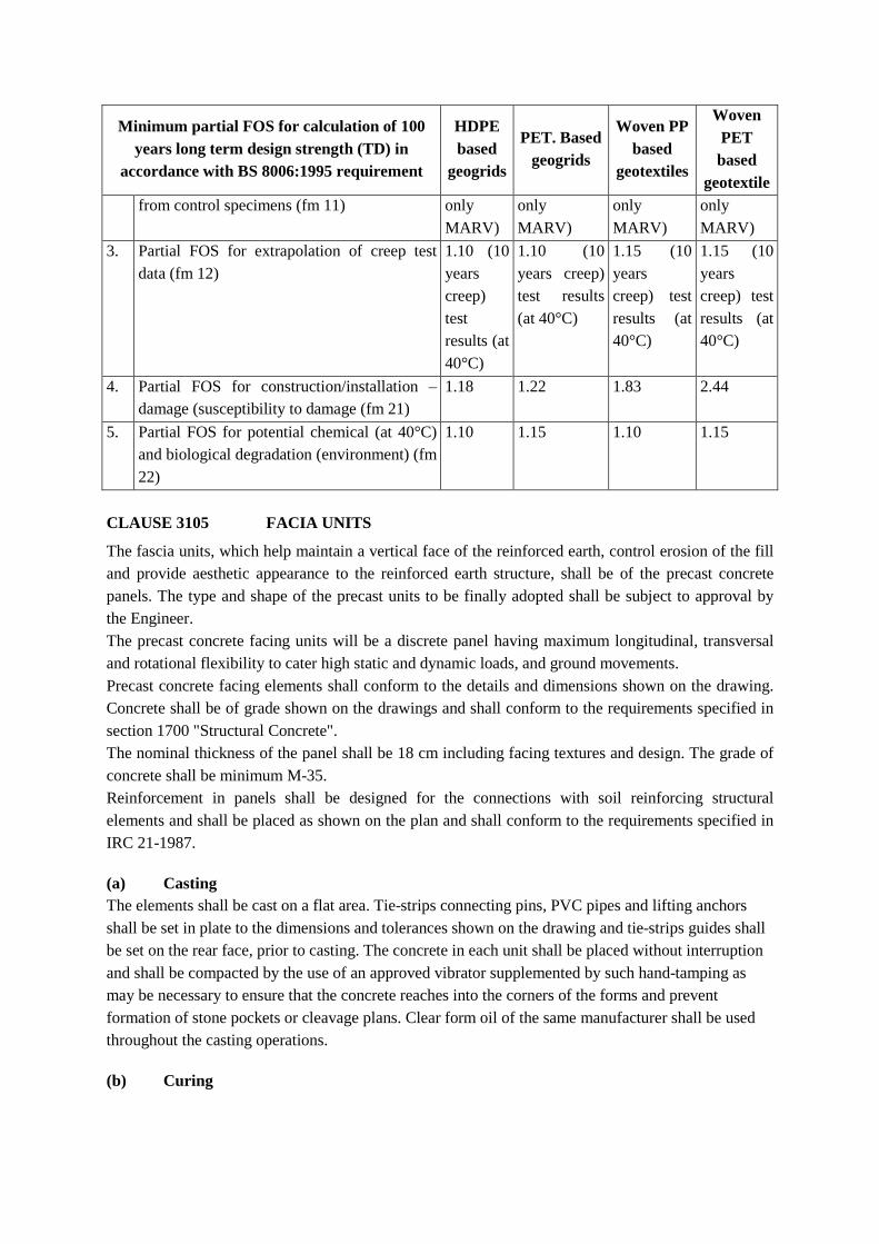
Minimum partial FOS for calculation of 100 years long term design strength (TD) in
accordance with BS 8006:1995 requirement
HDPE based
geogrids
PET. Based geogrids
Woven PP based
geotextiles
Woven PET
based geotextile
from control specimens (fm 11) only MARV)
only MARV)
only MARV)
only MARV)
3. Partial FOS for extrapolation of creep test data (fm 12)
1.10 (10 years creep) test results (at 40°C)
1.10 (10 years creep) test results (at 40°C)
1.15 (10 years creep) test results (at 40°C)
1.15 (10 years creep) test results (at 40°C)
4. Partial FOS for construction/installation – damage (susceptibility to damage (fm 21)
1.18 1.22 1.83 2.44
5. Partial FOS for potential chemical (at 40°C) and biological degradation (environment) (fm 22)
1.10 1.15 1.10 1.15
CLAUSE 3105 FACIA UNITS
The fascia units, which help maintain a vertical face of the reinforced earth, control erosion of the fill and provide aesthetic appearance to the reinforced earth structure, shall be of the precast concrete panels. The type and shape of the precast units to be finally adopted shall be subject to approval by the Engineer. The precast concrete facing units will be a discrete panel having maximum longitudinal, transversal and rotational flexibility to cater high static and dynamic loads, and ground movements. Precast concrete facing elements shall conform to the details and dimensions shown on the drawing. Concrete shall be of grade shown on the drawings and shall conform to the requirements specified in section 1700 "Structural Concrete". The nominal thickness of the panel shall be 18 cm including facing textures and design. The grade of concrete shall be minimum M-35. Reinforcement in panels shall be designed for the connections with soil reinforcing structural elements and shall be placed as shown on the plan and shall conform to the requirements specified in IRC 21-1987.
(a) Casting The elements shall be cast on a flat area. Tie-strips connecting pins, PVC pipes and lifting anchors shall be set in plate to the dimensions and tolerances shown on the drawing and tie-strips guides shall be set on the rear face, prior to casting. The concrete in each unit shall be placed without interruption and shall be compacted by the use of an approved vibrator supplemented by such hand-tamping as may be necessary to ensure that the concrete reaches into the corners of the forms and prevent formation of stone pockets or cleavage plans. Clear form oil of the same manufacturer shall be used throughout the casting operations.
(b) Curing

The precast elements shall be cured for a sufficient length of time as approved by Engineer so that the concrete develops the required compressive strength. Only fresh potable water shall be used for curing.
(c) Removal of Forms
The forms shall remain in place until they can be removed without damaging the elements. The scheme of removal of formwork shall be as per relevant M.O.R.T & H specifications.
(d) Scribing
The date of manufacture, batch number and panel designation shall be clearly scribed on the rear face of each unit.
(e) Concrete Finish
The front (exposed) face of the elements shall have the finish approved by the Engineer and painted with cement based waterproof paint or as decided by the Engineer. The rear face shall have the finish of unformed surface and shall be roughly screened to eliminate open pockets of aggregates.
(f) Tolerances All elements shall be manufactured within the following tolerances: - All dimensions: within 5 mm
- Evenness of the front face: ± 5 mm over 1500mm - Difference between lengths of two diagonals: maximum 10mm.
- Thickness: ± 5 mm
(g) Handling Storage and Transporting
All elements shall be handled, stored and transported in such manner as to eliminate the danger of chipping, cracks, fracture and excessive bending stresses. Elements in storage shall be supported on firm blocking located adjacent to the strips to avoid bending.
(h) Acceptability
Acceptability of the precast elements shall be determined on the basis of compression tests, as per M.O.R.T & H. specifications and visual inspection. A minimum of one sample of 6 cubes shall be taken for each lot of 5 cubic metre or part thereof produced per day. 50% of these cubes shall be cured in the same manner as the elements and tested to determine when the elements can be placed in the structure. Elements shall be acceptable for placement in the structure if the strength at 7 days, or before, exceeds 75% of the 28 days requirements. However, in no case these shall be placed in position before 7 days of casting the elements.
(i) Rejection
Elements shall be subject to rejection in case of failure to meet any of the requirements specified above. In addition, defects, which indicate imperfect molding, or defects indicating honeycombed or open textured concrete, shall be sufficient cause for rejection.
CLAUSE 3106 DRAINAGE

Drainage shall be very strictly followed as per drawing and specifications in detail. The Reinforced Earth backfill is considered a self-draining media, having sufficient permeability to relieve hydrostatic pressures. However, waterlogging in the reinforced fill increases the pore pressure coefficient thereby resulting in tensile forces in Reinforced Soil Structure, reducing the stability of structure.
Wherever, there is a probability of such occurrence, drainage outlets at the bottom level joints of panels with provision of non-woven geotextile backing shall be provided along the facia for drainage redundancy. The geotextile used as filter shall meet the requirements of MORTH Specifications of Road and Bridge Works, Clause 702.2.3.
The retained fill shall have drainage bay, minimum 600mm wide, with 19.5mm to 9.1mm well graded crushed aggregate with fine contents <5% to allow free draining of the reinforced fill along with the retained fill. The panel joints above 300mm of existing ground level shall be filled with joint fillers as per Item 7.0 and as approved by the Engineer.
CLAUSE 3106 LEVELING CONCRETE A leveling concrete pad shall be provided under the walls and seat beams (for - bridge abutments). Concrete shall have a minimum grade M-15 (150 kg/cm2). Maximum size of aggregates shall be 20mm and the pad shall be cured for at least 48 hours before placement of panels. CLAUSE 3107 JOINT FILLERS Fillers of vertical joints between panels shall be flexible open cell polyurethane foam strips or non-woven fabric strips (the latter used as joint cover instead of filter) as approved by Engineer. Bearing pads for horizontal joints between panels shall be made of elastomer with vulcanised EPDM.
CLAUSE 3108 CONSTRUCTION REQUIREMENTS CLAUSE 3108.1 EXCAVATION The Contractor shall excavate to the lines and grades shown on the project grading plans. The contractor shall take precautions to minimise over- excavation. Excavation support, if required shall be designed by the Contractor. CLAUSE 3108.2 FOUNDATION PREPARATION
The foundation for Reinforced Soil Structures shall be graded level for a width equal to or exceeding the length of reinforcing geosynthetics. Prior to wall construction, if required by the Engineer, the foundation shall be compacted with a smooth wheel vibratory roller. Where foundation soil is found to be unsuitable, either removal and replacement technique or ground improvement is required to be carried out, as approved by the Engineer. Foundation preparatory works and foundation treatment/ improvement shall be treated as integral part of the reinforced soil structure and accordingly Contractor shall arrange for detailed sub-soil investigation works and employ his resources to design and construct the foundation/ ground improvement treatment, wherever necessary to satisfy the requirements of reinforced soil structure. The design check and validation for foundation treatment/ ground improvement and the methodology shall be verified and approved by the Engineer prior to construction. The depth of foundation below the finished ground level shall not be less than 1000mm.

CLAUSE 3108.3 ERECTION Precast concrete panels shall be placed vertically with the aid of a light crane. For erection, panels are handled by means of lifting devices set into the upper edge of the panels. Panels shall be placed in successive horizontal lifts in the sequence shown on the drawings as backfill placement proceeds. As fill materials is placed behind a panel, the panels shall be maintained in vertical positions by means of temporary wooden wedges placed in the joint at the junction of the two adjacent top rows of panels during construction. As construction proceeds, and a fourth row is erected, the lowest row of wedges can be removed and so on. External bracing may also be needed for the initial lift. However, bracings shall be placed in an area not more than 1.5m wide beyond the outer face of panels.
Vertical tolerances (plumbness) and horizontal alignment tolerance shall not exceed 25mm when measured along a 3 m straight edge. The maximum allowable offset in any panel joint shall be 25mm.
CLAUSE 3108.4 SOIL REINFORCEMENT PLACEMENT All reinforcements shall be installed at the proper elevation and orientation as shown in the wall details on the construction plans or as directed by the Engineer. The reinforcement strips shall be placed normal to the face of the wall unless otherwise shown on the drawings.
The geogrid reinforcement shall be laid in one continuous length in principal strength direction (perpendicular to the wall face); no jointing by overlap, sewing or mechanical jointing shall be allowed in the principal strength direction. Adjacent sections of the geogrid reinforcement shall be placed in a manner to assure that the horizontal coverage shown on the plans is provided. A minimum 100mm overlap shall be allowed between adjacent roll widths.
Geogrid reinforcement should be installed under tension. A nominal tension shall be applied to the reinforcement and maintained by staples, stakes or hand tensioning until the reinforcement has been covered by at least 200mm of soil fill.
Broken, chipped, stained or otherwise damaged units shall not be placed in the wall unless they are repaired and the repair method and the results shall be subject to approval by the Engineer.
CLAUSE 3108.5 BACKFILL PLACEMENT The reinforcing elements shall be laid free from all kinks, damage and displacement during deposition, spreading, leveling and compaction of the fill. The programme of filling shall be such that no construction plant runs directly on the reinforcement. It shall be ensured that the exposure of soil reinforcement to ultraviolet rays is minimal and should be covered with earth within one day of placement.
All construction plant having a mass exceeding 1000 kg shall be kept at least 1.5m away from the face of slope or wall. In this area (upto 1.5m from the face of slope or wall), the following compaction plant shall be used.
(i) Vibratory roller having a weight per meter width of roll not exceeding 1300 kg with total
weight not exceeding 10,000 kg. (ii) Vibratory plate compactor of maximum weight 1000 kg.

(iii) Vibro tamper having a weight not exceeding 75 kg.
Compaction by any other method like using dozer or back blade compaction by dozer or excavator bucket shall be permitted with due approval from the engineer after ascertaining the level of compaction so achieved.
During construction of reinforced fill, the retained material beyond the reinforcement at the rear of the structure shall be maintained at the same level as reinforced fill. The entire works related to compaction should be carried out generally in a direction parallel to the facing. Fill placement methods near the facing shall ensure that no voids exist below the reinforcing elements.
Temporary formwork shall be used to support the construction as per specified details given in the drawing. The forms, scaffolding and props shall be sufficient in numbers to allow taking up of a sectoral construction schedule as specified in the design.
At the end of each day’s operations, the contractor shall shape the last level of backfill as to permit run-off rainwater away from the wall face.
CLAUSE 3108.6 DRAINAGE FILL PLACEMENT i) Drainage fill shall be placed to the minimum finished thickness and widths shown on the
construction plans or as modified by the Engineer. During placement and compaction of drainage material, care must be taken to ensure that there is no contamination with undesirable materials. Vertical layers of drainage layer material shall be brought up at the same rate as the adjoining fill material.
ii) Drainage collection pipes shall be installed to maintain gravity flow of water outside of the
reinforced soil zone. The drainage collection pipe should discharge into a storm sewer, manhole or along a slope at an elevation lower than the lowest point of the pipe within the aggregate drain.
iii) The main collection drainpipe just behind the precast facing, if used, shall be a minimum of 150mm in diameter. The secondary collection drain pipes should be sloped a minimum of two percent to provide gravity flow into the main collection drainpipe. Drainage laterals shall be spaced at a maximum 15 meters spacing along the wall face. The drainage collection pipe shall be a perforated or slotted, PVC or corrugated HDPE pipe. The pipe and drainage aggregate shall be wrapped with a geotextile that will function as a filter.
iv) More efficient drainage system, if possible, may be suggested by the proprietary contractor.
CLAUSE 3109 DESIGN, WORKING DRAWING, DETAILING AND SUPERVISION The scope of work will also cover the supply of detailed design, engineering submission of working drawings by the specialized agency for reinforced soil works. The designs and drawings shall be got approved from the Engineer and/or its representative before execution of work.
Technical representative of the supplier/manufacturer shall be present on site throughout during the entire working phase to ensure that the quality of the works performed by the Contractor is in accordance with the specifications. All expenses relating to this presence on site shall be deemed to have been included in the rate.

CLAUSE 3110 INSPECTION Engineer and/or the representative shall verify the materials supplied by the contractor to ensure that all the requirements of the specifications are satisfactorily met with. This includes all submittals and proper installation of the system.
As requested by Engineer and/or its representative, the reinforced earth retaining wall system supplier shall provide one qualified and experienced representative at site on full time basis to assist the Contractor regarding proper wall installation.
The Contractor’s field construction supervisor shall have demonstrated experience and should be qualified to direct all work at the site.
CLAUSE 3111 TESTING OF MATERIALS
i) Testing shall be done as stated elsewhere in this specification on all materials required for reinforced soil structure construction. The tests shall be done from a reputed independent agency as approved by Engineer as and when required. Tests on materials and during construction shall not be limited to the following types.
ii) Testing of soils for evaluating their index and engineering properties. Soil report may be consulted with regard to this requirement.
iii) Testing of friction angle between the reinforcement and soil using direct shear test.
iv) Testing of Reinforcements
(a) For design of reinforced soil structure, tensile strength, yield stress, elongation and modulus of elasticity of the reinforcement material are required. Both these properties for the steel reinforcement can be obtained from standard tensile test.
(b) For connection strength between geogrid/metallic reinforcement and facing where connection strength should have appropriate factor of safety against the connection load calculated as per BS 8006: 1995.
(c) The geosynthetic properties can be determined using standards as summarized below:
Tensile strength test
ASTM 1682, 1975 BS 2576 IS 1969-1985
A 50mm x 300mm sample clamped to give a gauge length of 200mm and stretched at constant rate of 200mm per minute till breakage. Breaking load and extension at breakage are recorded.
Grab tensile test ASTM 1682, 1975 200mm wide sample with gauge length of 100mm is tensioned at constant rate until failure.
Wide width tensile test
ASTM D-4596 A sample of 200mm or 500mmx200mm clamped across width to give a gauge length of 100mm, which is tensioned at 200mm per minute breaking load and extension at breakage recorded.
Tear Tests ASTMD 4533-85 Fabric’s resistance to propagating a tear is given by this test.
Muller’s Burst ASTMD 3786-77 Burst resistance is the resistance of the fabric to

test &BS 4768 withstand the localized pressure. Ball burst test ASTMD 3787-77 -DO- CBR push through test
ASTM STP 952 P.57-68
-DO-
CLAUSE 3112 MEASUREMENT FOR PAYMENTS
i) The measurement of reinforced earth shall only be for concrete discrete panels in vertical square meters of the final finished concrete facia after erection from top of the levelling pad to the top of facia wall.
ii) The measurement for payment of compacted earth fill shall be in cubic meters for compacted soil and shall be made against relevant items of fill behind reinforced soil structures.
CLAUSE 3113 RATE
i) The overall rate for reinforced earth shall include detailed engineering including designs, drawings, all specified quality control tests, approval from Engineer, furnishing, fabricating and providing all materials for the walls including facia panels, reinforcing elements and all its accessories, excavation and foundation construction; setting out and erection of wall materials including facia panels with all joint materials, reinforcement etc., supplying and placing of drainage works, filter medium and filter fabric, providing friction slab and crash barrier and any foundation treatment/ ground improvement based on field and laboratory sub-soil investigation, if required etc.
The rate shall include the cost of labour, plant/ machinery, material storage and handling expenses, as required for all the above activities for completing the works.
The rate for facia panels shall cover the cost of all materials, castings, curing, and quality control tests, stacking, transporting and placing of concrete discrete panels. Cost of joints, all necessary temporary formwork, scaffolding and all lifts and leads complete as per approved design/ drawing of the specialised firm shall also be included.
Rate for providing reinforcing elements shall include material cost, all transportation costs and storage of the same as per special provisions. The rate shall also include cost of quality control tests, laying of the reinforcing elements including all overlaps, jointing or stitching, heat bonding or extension and jointing them with reinforcing elements of concrete discrete panels along with all accessories.
Rate for foundation and capping beam shall include all items of excavation, concrete, reinforcing steel, formwork, curing etc.
Rate for drainage shall cover providing, placing and compacting drainage aggregate, filter medium including drainage collection pipe, filter fabric and conducting quality control tests etc.
ii) The rate for soil fill shall include selection, supply, placing, compaction, and quality control tests etc. for approved earth fill. The rate shall also include the cost of labour, plant/ machinery,

transportation for all leads and lifts etc. as required for completing the works.

ADDITIONAL SPECIFICATIONS

The following Clauses have been added to the “SPECIFICATIONS FOR ROAD AND BRIDGE WORKS”.
A-1 Reusing of Existing Pavement and Temporary Diversion Material in the Permanent Road Works
A-2 Surface sealing cracks by PMC mortar.
A-3 Application of PMC mortar on exposed reinforcement etc.
A-4 Repair of mortar less joints in masonry.
A-5 Replacement by Microconcrete.
A-6 Specification for sand blasting.
A-7 Adding reinforcement to existing structure by drilling holes.
A-8 Remedial measure against scouring.
A-9 Replacement/rectification of bearing.
A-10 Replacement of heavily corroded steel members and splices.
A-11 Provision of Asphaltic plug expansion joint.
A-12 Erection of Single sided and Double guard rail crash barriers.
A-13 Quality control and post repair tests.
A-14 Polysulphide
A-15 Paver Block
A-16 Reflective Studs
A-17 Bus Shelter
A-18 Tactile Blocks

CLAUSE A-1 :- RE-USING OF EXISTING PAVEMENT AND TEMPORARY DIVERSION MATERIAL IN THE PERMANENT ROAD WORKS.
The following clauses shall apply to any pavement materials excavated during the course of the contract that can be successfully salvaged and re-used in the proposed road widening in the lower pavement works (selected fill, sub-grade or sub-base). The materials considered suitable for re-use include bitumen bound layers, water bound macadam, wet mix base, concrete, quarry waste, bricks or kankar provided they comply with the following specifications for use as suitable fill. The material shall have a nominal maximum size of 100mm with the percentage exceeding this size being less than 10%, with zero percent exceeding 150mm. Materials exceeding 150mm size must either be broken down in site by handling or by the action of a vibratory roller or removal by hand picking out of the fill material. For use as a select sub-grade or lower sub-base layer, the nominal maximum size shall be 50mm with less than 10% passing this size, and the zero percent exceeding 75mm size. The material should also satisfy the specified properties for select sub-grade and sub-base as required, with respect to CBR & PI.
CLAUSE A-2 :-SURFACE SEALING OF CRACKS BY PMC MORTAR
ITEM: Sealing of cracks by PMC mortar including making groove, surface preparation, filling it by mortar, curing, supplying of material etc. all complete and as per the Technical Specification.
A-2.1 General
This will apply to all cracks other than sealed by injecting epoxy grout or cement grout.
A-2.2. Materials
Cement: Portland cement conforming to IS:8112 shall be used for production of PMC mortar. Pre-packaged repair mortar of equivalent quality of any brand may be used if approved by the Engineer.
Mortar modifier: Mortar modifier shall be as approved by the Engineer. The mortar modifier shall be styrene butadiene emulsion specially designed for use as a gauging liquid for cementitious systems. The emulsion should be able to reduce the permeability of typical 1:3 cement-sand mortar by minimum 80% and flexural strength should be improved by minimum 15%. The mechanical properties of typical 1:3 cement-sand mortar shall be tested as per BS-6319 at 28 days air cured.
Sand: The sand to be used for making the PMC mortar shall be of zone-II as per IS-383.The sand to be used must satisfy the limits of deleterious materials and requirements of soundness as given in Clause 3.2.1 and Clause 3.6 of IS:383. Confirmatory tests shall be conducted by the contractor and sample of approved sand deposited with the Engineer. For consistent performance the use of clean and dry sand is essential. Where wet sand isto be used for any reason, moisture content for sand shall be determined at site laboratory and mixing water quantity shall be adjusted accordingly.
Reinforcement primer: The primer shall be as approved by the Engineer, a two pack zinc-rich liquid packed and supplied and ready to use. An unbroken 40 microns thick coating shall be capable of providing “active” galvanic protection and of avoiding the generation of incipient

anodes in the immediately adjacent locations. It shall be a suitable viscosity to enable the coating to penetrate imperfections and pits within surface of corrosion-damaged steel bars. The formulation of primer shall be such that drying proceeds after 20 to 40 minutes at 35 degree C or after 30 minutes to one hour at 20 degree C. The primer should confirm requirements of BS-4652:1971.
A-2.3. Mix Formulations for PMC Material System
Primer slurry Cement 3 volumes
Modifier 1 volume Water 1 volume
PMC repair mortar Cement 50 Kg Modifier 5.0 Liters Zone II sand 150 Kg W/C 0.35
A-2.4.Mixing of materials
The mixing of materials in proportions indicated above shall be carried out using forced action mixer or with slow speed drive mixer (400-500 rpm) fitted with a spiral paddle. Remixing and re-tempering shall not be permitted. The mix ready to use mortar shall not contain lumps of any type and shall be uniform in colour .In order to obtain a smooth consistency the cement should be blended slowly into the liquids. Stir frequently during use to offset settlement.
A-2.5.Surface Preparation
The size of the groove to be cut along the whole length of the visible cracks shall be 20 mm wide x 10mm deep and shall be symmetrically placed along the crack. In case the reinforcement is met within the depth of 10 mm, the depth shall be limited to the reinforcement depth from the surface. It is preferable to cut the groove perpendicularly to the surface but a deviation of 15 degrees in either direction may be permitted.
After cutting the groove it shall be cleaned properly using steel brushes and other appropriate tools to ensure a dust free clean surface, and, a layer of primer slurry coating shall be applied over the freshly cut surfaces.
A-2.6.Application of PMC mortar
The minimum application temperature shall be 10 degree C. The PMC mortar application should be wet and the wet primer must not be allowed to dry. If the primer slurry dries out it must be removed and the clean substrate re-primed. The PMC mortar shall be compacted to ensure complete filling of the groove. The filling up of the groove shall be finished flush with the existing concrete surface.
(i) The water curing shall be carried out strictly as per MORTH specification clause no.1713.
(ii) Alternatively in order to avoid rapid drying of finished surface, curing of the finished surface may be done using curing compound as approved and permitted by Engineer.

A-2.7.Tests and Standards of Acceptance
All the materials used for repair shall be tested in accordance with clause 2.2.6 of this document and MORTH Specification and shall meet the prescribed criteria.
A-2.8. Measurements for Payment
Measurement for sealing of cracks shall be made per meter length of crack repaired.
A-2.9. Rate
The contract unit rate of crack sealing shall include cost of all materials, labour, tools & plants, scaffolding, surface preparation, and curing, testing and other incidental expenses for satisfactory completion of the work as per the specification.
A-2.10.Applications
Sealing of cracks by PMC mortar is applicable to cracks as shown on drawings or decided by The Engineer .In general vertical surface cracks in girder webs, Cracks in cement concrete piers, cracks in well foundation etc., shall be sealed using PMC mortar.
CLAUSE A-3: APPLICATION OF PMC (POLYMER MODIFIED CEMENTITIOUS) MORTAR ON EXPOSED REINFORCEMENT ETC.
ITEM: Applying PMC mortar over honeycombed and spalled concrete surface and exposed steel reinforcement complete as per Technical Specifications.
A-3.1. General
This specification covers the repair of leached, honeycombed and spalled concrete and patched spots of existing concrete by low permeability polymer modifiedcementitious (PMC) mortar. This application is limited to a maximum thickness of 75mm.In case thickness of repair exceeds 75mm use micro-concrete or normal M25 concrete as directed by the Engineer.
A-3.2. Materials
Cement: Portland cement conforming to IS:8112 shall be used for production of PMC mortar. Pre-packaged repair mortar of equivalent quality of any brand may be used if approved by the Engineer.
Mortar modifier: Mortar modifier shall be as approved by the Engineer. The mortar modifier shall be styrene butadiene emulsion specially designed for use as a gauging liquid for cementitious systems. The emulsion should be able to reduce the permeability of typical 1:3 cement-sand mortar by minimum 80% and flexural strength should be improved by minimum 15%. The mechanical properties of typical 1:3 cement-sand mortar shall be tested as per BS-6319 at 28 days air cured.
Sand: The sand to be used for making the PMC mortar shall be of zone-II as per IS-383.The sand to be used must satisfy the limits of deleterious materials and requirements of soundness as given in Clause 3.2.1 and Clause 3.6 of IS: 383. Confirmatory tests shall be conducted by the contractor and sample of approved sand deposited with the Engineer. For consistent performance the use of clean and dry sand is essential. Where wet sand is to be used for any reason, moisture content for

sand shall be determined at site laboratory and mixing water quantity shall be adjusted accordingly.
Reinforcement primer: The primer shall be primer approved by the Engineer, a two pack zinc-rich liquid packed and supplied and ready to use. An unbroken 40 microns thick coating shall be capable of providing “active” galvanic protection and of avoiding the generation of incipient anodes in the immediately adjacent locations. It shall be a suitable viscosity to enable the coating to penetrate imperfections and pits within surface of corrosion-damaged steel bars. The formulation of primer shall be such that drying proceeds after 20 to 40 minutes at 35 degree C or after 30 minutes to one hour at 20 degree C. The primer should confirm to the requirements of BS-4652: 1971.
A-3.3. Mix Formulations for PMC Material System
Primer slurry Cement 3 volumes
Modifier 1 volume Water 1 volume
PMC repair mortar Cement 50 Kg Modifier 5.0 Liters Zone II sand 150 Kg W/C 0.35
A-3.4.Mixing of materials
The mixing of materials in proportions indicated above shall be carried out using forced action mixer or with slow speed drive mixer (400-500 rpm) fitted with a spiral paddle. Re-mixing and re-tempering shall not be permitted. The mix ready to use mortar shall not contain lumps of any type and shall be uniform in colour. In order to obtain a smooth consistency the cement should be blended slowly into the liquids. Stir frequently during use to offset settlement.
A-3.5. Surface PreparationConcrete
All defective areas will be delineated with paint and got approved from the Engineer. The defective areas will be neatly cut around the perimeter to a minimum depth of 10mm. Special portable mechanical tools of make approved by the Engineer shall be used for above purpose. The cut will be perpendicular to the surrounding concrete face. No cut will be “feather edged”.
All defective, cracked or weak concrete shall be removed by using appropriate tools and equipment. Where the reinforcement bars are exposed, the removal shall continue till full circumference of the steel is exposed and to a further depth of 10mm or as directed by the Engineer.
The equipment and methods used to break out the concrete shall be such that no reinforcement bar or other embedment items are loosened or damaged.
In situation where reinforcement is congested, making removal of concrete by mechanical means difficult, then the use of high pressure water jetting or other appropriate method can be proposed by the Contractor for approval of the Engineer.
The concrete surface shall be finally sand blasted as per clause A-6 to ensure that it is sound and clean and free of loose particles, dust and debris.

Before application of PMC mortar, the prepared concrete substrate shall be thoroughly soaked with clean water. Free surface water shall be removed before priming. The primer shall be primer slurry recommended above.
The primer shall be worked well into the irregularities of the substrate by using a scrubbing action according to the manufacturer’s recommendations.
Reinforcement
All exposed reinforcement shall be cleaned in accordance with the following:
a. Where exposed reinforcement is sound and does not show any signs of heavy corrosion or pitting other than typical rusting, it shall be mechanically cleaned to remove rust and loose mill-scales. It is always preferable to clean the steel to a bright condition.
b. Where exposed reinforcement shows signs of heavy corrosion/deterioration it shall be cleaned by sand blasting or by proprietary rust removing compound if permitted by the Engineer and then treated as given in subsequent para of this Specification.
Within one hour of preparing and cleaning the reinforcement shall be coated with specified primer. The primer should be brush applied on to the cleaned reinforcement ensuring that the full surface area is covered in accordance with the manufacturer’s recommendation.
Repair of Corroded Reinforcement
The diameter of the reinforcement which shows sign of heavy corrosion should be measured by callipers or other approved instrument. If it is found that cross-section of the existing reinforcement has reduced by more than 20% of the original cross-section, the reinforcement has to be replaced by HYSD bar of equal diameter or higher diameter. HYSD bars shall conform to IS 1786 and Clause 1009.3 of MORTH specifications.
Procedure for replacement of corroded/damaged reinforcement
The concrete surface in the vicinity of the corroded reinforcement has to be chipped-off for 1m length on both sides. The chipping shall continue till full circumference of reinforcement and further depth of 10mm is exposed. The chipped surface is to be cleaned thoroughly by sand blasting. New HYSD bars cut to pieces are to be placed by the side of the old reinforcement and fixed to it to ensure proper bonding after providing required lap length. After replacement, it is primed using specified reinforcement primer.
A-3.6.Application of PMC Mortar on Concrete Substrate
The total thickness of PMC mortar shall be applied in single or multiple layers depending upon the depth of the repair, in accordance with the manufacturer’s recommendations. If any difficulty is experienced in applying in more than one layer, the manufacturer shall be consulted.
The material shall be applied by gloved hand or trowel to the prepared and primed surface of the substrate and be well worked inside paying particular attention to packing behind and between the reinforcements. In case where two or more layers of PMC mortar are to be used, the each subsequent layer shall be provided after a lapse of 24 hours from the time of application of the earlier layer. Conventional practice of surface preparation for good bonding shall be adopted for all interfaces.

A-3.7. Curing
A. The water curing shall be carried out strictly as per MORTH specification Clause No.1713.
B. Alternatively in order to avoid rapid drying of finished surface, curing of the finished surface may be done using curing compound as approved and permitted by the Engineer.
A-3.8.Cleaning and maintenance of Equipment
Tools and equipment are best cleaned immediately after use since removal of cured mix is difficult and time consuming. The bulk of mix shall be removed using a scraper and remainder washed away completely using solvents prescribed by the manufacturer.
A-3.9 Tests and Standards of Acceptance
All the materials used for repair shall be tested in accordance with clause 2.2.6 of this document and MORTH Specification and shall meet the prescribed criteria.
A-3.10.Measurements for Payment
Measurement for payments for above item is divided into three parts as listed below:-
(i) Measurement for surface preparation of concrete using sand blasting or other approved techniques and application of primer slurry shall be measured in sq m of surface area of application.
(ii) Measurement for surface preparation of existing corroded reinforcement and applying reinforcement primer shall be measured in tonnes of HYSD bars utilised in the work.
(iii) Measurement for application of PMC mortar for specified thickness shall be per square meter of surface area of application.
A-3.11. Rate
The contract unit rate for surface preparation of concrete using sand blasting or other approved techniques and application of primer slurry shall include cost of all materials, labour, tools and plant, temporary works and other incidental works as required for the satisfactory completion of the item complete as per these specification and also as per direction of the Engineer.
The contract unit rate for surface preparation of existing corroded reinforcement and applying reinforcement primer shall include cost of all materials, labour, tools and plant, temporary works and other incidental works as required for the satisfactory completion of the item complete as per these specification and also as per direction of the Engineer.
The contract unit rate for application of PMC mortar for specified thickness shall include cost of all materials, labour, tools and plant, scaffolding, placing in position, testing, traffic management, safety precautions and other incidental expenses including, curing, etc. complete for the satisfactory completion of the work as per these specifications and also as per direction of the Engineer.
A-3.12.Applications

In general above item is applicable to repair to exposed reinforcement at soffit of deck slab, spalling of concrete in general, exposed reinforcement in diaphragms, local voids in girder etc. subjected to removal of maximum 75mm thick layer of honeycomb concrete, exposed reinforcement in well cap, exposed reinforcement in pier cap.
CLAUSE A-4 :-REPAIR OF “MORTAR-LESS” JOINTS IN MASONRY
ITEM: Repair of “mortar-less” joints in masonry with PMC mortar including removal of old mortar, cleaning, packing of mortar, labour, material, scaffolding etc. all complete as per Technical Specification.
A-4.1.General
This specification shall apply for “mortar-less” joints in masonry structures, mainly in the substructure of the bridges and in soffits of arch structures.
A-4.2. Materials
Cement: Portland cement conforming to IS:8112 shall be used for production of PMC mortar. Pre-packaged repair mortar of equivalent quality of any brand may be used if approved by the Engineer.
Mortar modifier: Mortar modifier shall be as approved by the Engineer. The mortar modifier shall be styrene butadiene emulsion specially designed for use as a gauging liquid for cementitious systems. The emulsion should be able to reduce the permeability of typical 1:3 cement-sand mortar by minimum 80% and flexural strength should be improved by minimum 15%. The mechanical properties of typical 1:3 cement-sand mortar shall be tested as per BS-6319 at 28 days air cured.
Sand: The sand to be used for making the PMC mortar shall be of zone-II as per IS-383.The sand to be used must satisfy the limits of deleterious materials and requirements of soundness as given in Clause 3.2.1 and Clause 3.6 of IS: 383. Confirmatory tests shall be conducted by the contractor and sample of approved sand deposited with the Engineer. For consistent performance the use of clean and dry sand is essential. Where wet sand to is be used for any reason, moisture content for sand shall be determined at site laboratory and mixing water quantity shall be adjusted accordingly.
A-4.3. Mix Formulations for PMC Material System
Primer slurry Cement 3 volumes
Modifier 1 volume W/C 1 volume PMC repair mortar Cement 50 Kg Modifier 5.0 Litres Zone II sand 150 Kg W/C 0.35

A-4.4.Mixing of materials
The mixing of materials in proportions indicated above shall be carried out using forced action mixer or with slow speed drive mixer (400-500 rpm) fitted with a spiral paddle. Re-mixing and re-tempering shall not be permitted. The mix ready to use mortar shall not contain lumps of any type and shall be uniform in colour. In order to obtain a smooth consistency the cement should be blended slowly into the liquids. Stir frequently during use to offset settlement.
A-4.5.Surface Preparation
The “mortar-less” joints shall be located by site inspection jointly with the Engineer’s representative and delineated by paint and documented.
Prior to replenishing the joints with PMC mortar, the “mortar-less” joints shall be properly cleaned by some blunt pointed poker so as to remove all loose material.
The joint shall then be cleaned with compressed air using a small diameter metallic nozzle so as to drive out loose dirt dust etc. sticking on the faces of the joints.
The replenishment of mortar should be carried out till the newly applied mortar is flush with the adjacent masonry.
It is preferable to impose traffic restriction on the bridge during the process of filling up of the joints especially restricting the passage of heavy vehicles over the portion where the replenishing process is in progress. Thus it may be wise to carry out joint repair in half the width of the bridge at one time and allowing traffic in other half
A-4.6.Application of PMC mortar
After cleaning with compressed air, the joints shall be sprayed with water prior to being filled with PMC mortar. If the depth of “mortar-less” joints is more than 100mm, proper care should be taken to ensure entry of the mortar inside the joints. Proper ramming with a blunt edge tapered rammer, (8mm to 12mm) having a width of 150-200 mm should be used for ramming the mortar inside the joints.
The minimum application temperature shall be 10 degree C. The PMC mortar application should be wet on wet; the primer must not be allowed to dry. If the primer slurry dries out it must be removed and the clean substrate re-primed.
C. The water curing shall be carried out strictly as per MORTH specification clause no.1713.
D. Alternatively in order to avoid rapid drying of finished surface, curing of the finished surface may be done using Concure WB, curing compound of Fosroc or equivalent provided its permitted by the Engineer.
A-4.7.Tests and Standards of Acceptance
All the materials used for repair shall be tested in accordance with clause 2.2.6 of this document and MORTH Specification and shall meet the prescribed criteria.
A-4.8. Measurements for Payment
Measurement for repair of mortar-less joints shall be made per meter length of joint repaired.

A-4.9. Rate
The contract unit rate of repair of mortar-less joints shall include cost of all materials, labour, tools & plants, scaffolding, surface preparation, and curing, testing and other incidental expenses for satisfactory completion of the work as per the specification.
CLAUSE A-5 :-REPLACEMENT BY MICRO-CONCRETE
ITEM: Concrete replacement using high-strength, free-flowing, cementitious micro-concrete including removal of loose material, surface preparation, supplying of material, labour, scaffolding, formwork, tools and plant etc. all complete and as per the Technical Specifications.
A-5.1.General
This will apply to large areas of deeply honeycombed concrete, deep patches due to spalling of concrete or repair of exposed reinforcement area in case thickness of repair is more than 75mm or concrete damaged by physical forces such as impact or erosion
A-5.2.Materials
Micro-concrete
The repair material shall be as approved by the Engineer and shall
be shrinkage compensated in both liquid and cured states
contain no metallic expansion system
be pre-packed and factory quality controlled
be a free-flowing cementitious material that has a coefficient of thermal expansion fully compatible with the host concrete.
be chloride free
Aggregate grading shall be as per following:
Sieve Size %age Passing 10mm 100% 8mm 95% 6mm 70% 4.75mm 15%
The micro-concrete shall be mixed and placed in accordance with the manufacturer’s recommendations, particularly with regard to water content, mixing equipment and placing time. The micro-concrete in the flowable consistency shall achieve a compressive strength of not less than 10N/sqmm after 24 hours at 300C, 25 N/sqmm after 72 hours, 35 N/sqmm and 45 N/sqmm strength at 28 days. The mixed material (only addition of water at site) should give a collapsible slump without bleeding segregation. The maximum size of the aggregate should not exceed above 8mm.
Reinforcement primer

The primer shall be as approved by the Engineer, a two pack zinc-rich liquid packed and supplied and ready to use. An unbroken 40 microns thick coating shall be capable of providing “active” galvanic protection and of avoiding the generation of incipient anodes in the immediately adjacent locations. It shall be a suitable viscosity to enable the coating to penetrate imperfections and pits within surface of corrosion-damaged steel bars. The formulation of primer shall be such that drying proceeds after 20 to 40 minutes at 350C or after 30 minutes to one hour at 200C. The primer should confirm requirements of BS-4652: 1971.
Mould release agent used shall be as approved by the Engineer.
A-5.3.Surface preparation
Concrete
All defective areas will be delineated with paint and got approved from the Engineer. The defective areas will be neatly cut around the perimeter to a minimum depth of 10mm. Special portable mechanical tools as approved by the Engineer shall be used for above purpose. The cut will be perpendicular to the surrounding concrete face. No cut will be “feather edged”.
All defective, cracked or weak concrete shall be removed by using appropriate tools and equipment. Where the reinforcement bars are exposed, the removal shall continue till full circumference of the steel is exposed and to a further depth of 10mm or as directed by the Engineer.
The equipment and methods used to break out the concrete shall be such that no reinforcement bar or other embedment items are loosened or damaged.
In situation where reinforcement is congested, making removal of concrete by mechanical means difficult, then the use of high pressure water jetting or other appropriate method can be proposed by the Contractor for approval of The Engineer.
The concrete surface shall be finally sand blasted as per clause A-6 to ensure that it is sound and clean and free of loose particles, dust and debris.
Before application of PMC mortar, the prepared concrete substrate shall be thoroughly soaked with clean water. Free surface water shall be removed before priming. The primer shall be primer slurry recommended above.
The primer shall be worked well into the irregularities of the substrate by using a scrubbing action according to the manufacturer’s recommendations.
Reinforcement
All exposed reinforcement shall be cleaned in accordance with the following:
a. Where exposed reinforcement is sound and does not show any signs of heavy corrosion or pitting other than typical rusting, it shall be mechanically cleaned to remove rust and loose mill-scales. It is always preferable to clean the steel to a bright condition.
b. Where exposed reinforcement shows signs of heavy corrosion/ deterioration it shall be cleaned by sand blasting or by proprietary rust removing compound if permitted be The Engineer and then treated as given in subsequent para of this Specification.

Within one hour of preparing and cleaning the reinforcement shall be coated with specified primer. The primer should be brush applied on to the cleaned reinforcement ensuring that the full surface area is covered in accordance with the manufacturer’s recommendation.
Repair of Corroded Reinforcement
The diameter of the reinforcement which shows sign of heavy corrosion should be measured by callipers or other approved instrument. If it is found that cross-section of the existing reinforcement has reduced by more than 20% of the original cross-section, the reinforcement has to be replaced by HYSD bar of equal diameter or higher diameter. HYSD bars shall conform to IS 1786 and Clause 1009.3 of MORTH specifications.
Procedure for replacement of corroded/damaged reinforcement
The concrete surface in the vicinity of the corroded reinforcement has to be chipped-off for 1m length on both sides. The chipping shall continue till full circumference of reinforcement and further depth of 10mm is exposed. The chipped surface is to be cleaned thoroughly by sand blasting. New HYSD bars cut to pieces are to be placed by the side of the old reinforcement and fixed to it to ensure proper bonding after providing required lap length. After replacement, it is primed using specified reinforcement primer
A-5.4.Formwork
Adequate formwork shall be provided in accordance with MORTH Specifications. This shall be securely fixed to withstand the hydraulic pressures of the fluid micro-concrete repair material without distortion or movement during placement. The formwork shall be watertight at all joints between panels and between the formwork and the existing concrete surface so as to prevent material leakage. It shall also be sturdy and stable.
The formwork shall be constructed from appropriate materials as agreed with the Engineer to achieve the required finish.
Formwork surfaces that are to be in contact with the repair micro-concrete shall be treated with a suitable mould release agent such as ReebolofFosroc or equivalent. This shall be used in accordance with the manufacturer’s recommendations.
The formwork shall be inspected by the Engineer and, if approved, filled with clean water which:
demonstrates that the formwork is mortar-tight and,
saturates the prepared concrete surface.
The formwork shall be completely drained and resealed. The formwork shall not be removed until the repair micro-concrete has achieved a compressive strength of at least 10 N/mm2 or as directed by the Engineer.
A-5.5.Curing
The water curing shall be carried out strictly as per MORTH specification clause no.1713.
E. Alternatively in order to avoid rapid drying of finished surface, curing of the finished surface may be done using curing compound as approved and permitted by the Engineer.

A-5.6. Measurements for Payment
- Measurement for replacement by micro-concrete shall be made per cum of replaced volume.
- Measurement for added steel reinforcement shall be made per tonnes of steel reinforcement.
A-5.7. Rate
The contract unit rates of micro-concrete and any added steel reinforcement shall include cost of all materials, labour, tools & plants, scaffolding, surface preparation, and curing, testing and other incidental expenses for satisfactory completion of the work as per the specification.
A-5.7. Application
In general this item applicable to repair of deeply honeycomb of RCC girders bottom bulbs, diaphragms and where large volume of concrete are required to be replaced in structural elements like exposed area of reinforcement in well cap, pier/abut. cap and diaphragms or as directed by the Engineer.
CLAUSE A-6: SPECIFICATIONS FOR SAND BLASTING
ITEM: Preparation of concrete and reinforcement surface by Sand blasting prior to applying primer to concrete and reinforcement.
This item is applicable to all repair works where new concrete is to be bonded to old concrete and repair of areas requiring application of PMC mortar, Micro concrete, etc.
Dry coarse sand confirming to Zone I Defined in IS:383-1970 (Reaffirmed 1990) shall be used for sand blasting purposes. Application pressure shall range about 8 to 10 kg per sqcm. Compressor used shall have minimum capacity of 10 Cum/min.
Sand blasting equipment used shall beas approved by the Engineer.
Rate:
No separate payment shall be made for the above item and is incidental to repair works as applicable .It is highlighted that only a same item of the present specifications surface preparations (including sand blasting) is payable as measured item of work when specifically indicated.
CLAUSE A-7:-ADDING REINFORCEMENT TO EXISTING STRUCTURE BY DRILLING HOLES
ITEM: Adding reinforcement to existing structure by drilling holes, cleaning holes, filling holes with approved epoxy mortar, placing reinforcement bars in prepared holes and curing including all labour, material, plants and tools, scaffolding, etc. all complete and as per Technical Specifications.
A-7.1.General
Location of holes to be drilled shall be marked in paint. Prior to marking holes existing rebar locations shall be determined to ensure that none of the existing rebar interferes the hole drilling. For locating rebar instrument approved by the Engineer shall be used.

The holes for adding rebars shall be drilled using a rotary hammering action unit and shall be as approved by the Engineer. After drilling, holes shall be cleaned prior to filling with approved epoxy mortar.
Epoxy mortar shall be packed into drilled hole. Thereafter reinforcement shall be inserted into the epoxy mortar packed hole. Some mortar should overflow upon inserting the rebar to show complete filling. Allow for complete curing before application of any load.
The length of hole to be drilled shall be ten times the dia of rebar (10*dia). The correct drill diameter is important for the performance of the adhesive bond as well as for the economy of the application and shall be as per table give below.
Nominal Recommended Rebar diameter Hole diameter 8 mm 12 mm
10 mm 14 mm 12 mm 16 mm 16 mm 22 mm 20 mm 28 mm 25 mm 32 mm 28 mm 36 mm
A-7.2. Measurement for Payment
Measurement for adding reinforcement to existing structure shall be made separately for different elements of repairs as given below.
(i) Added reinforcement shall be paid in tonnes.
(ii) Payment for drilled holes shall be made in cubic cm of drilled hole volume and shall include packed epoxy mortar.
A-7.3.Rate
The contract unit rate for adding reinforcement shall include cost of all materials, labour, tools & plants to fabricate and install reinforcement bar and other incidental expenses for satisfactory completion of the work as per the specification
The contract unit rate for drilling holes shall include cost of all materials, labour, tools & plants, scaffolding, surface preparation, locating existing bars, filling drilled holes with epoxy grout, mortar, testing and other incidental expenses for satisfactory, and other incidental expenses for satisfactory completion of the work as per the specification
CLAUSE A-8:-REMEDIAL MEASURE AGAINST SCOURING
ITEM: Remedial measure against scouring consisting of casting cast-in-situ bored piles, plain cement concrete filling, adding reinforcement including labour, scaffolding, formwork, tools and plant etc. all complete and as per technical specifications.
A-8.1 General
This specification apply to foundation where scouring is evident for depth exceeding 2.5m (approximate) below top of well cap or as directed by the Engineer and is applicable to well foundations only.

This item consisting of various activities as shown in tender Drawings. Each activity shall be covered under individual header of the relevant General Technical Specification.
- Bored cast in situ piles shall be constructed as per MORTH specification clause 1107.
- Part of pile above existing bed level shall be treated as structural RCC column and shall be constructed as per MORTH specification clause 1700.
- PCC filling shall also be carried out as per MORTH specification clause no 1700.
- Adding reinforcement to existing structure shall be as per additional clause no A-7.
- Ring beam shall be constructed in conformity to MORTH specification clause no 1700.
- Addition of new reinforcement in ring beam and piles shall be as per MORTH Clause No 1600.
- Ground improvement by cement grouting under pressure shall be done as given below
The cement grout of required proportion shall be prepared in appropriate mixer (such as “concrete” mixer or approved equivalent) so as to obtain a colloidal mix. The prepared grout shall be pumped with the help of positive displacement reciprocatory type pump of approved manufacture with minimum output of 1200 liters per hour and working pressure of 10 kg/sqcm.
Pressure grouting shall be affected through pipe left in piles with packers placed in position or other approved method so that discharge takes place into the ground with specified pressure. As soon as any discharge is observed at surrounding ground, the mix proportion of cement grout shall be changed to thicker consistency as indicated in above mentioned drawing. The grouting shall be discontinued when the thicker consistency grout appears at the surrounding ground or as directed by The Engineer.
A-8.2.Tests and Standards of Acceptance
All the materials used for repair shall be tested in accordance with clause 2.2.6 of this document and MORTH Specification and shall meet the prescribed criteria
A-8.3 Measurement for payment
Measurement for various activities mentioned above shall be made as per respective reference clauses. Pumped cement grout shall be measured in kilograms of cement pumped.
A-8.4 Rate.
Contract unit rate for various activity mentioned above shall be made as per rate defined under relevant clauses defined for various activities.
Contract unit rate for ground improvement by cement grouting shall include installation of MS pipes, packers, hoses, couplers, all materials used for grouting, pumping using specified pumps and other incidental expenses for satisfactory completion of the work as per the specification.
CLAUSE A-9:- REPLACEMENT/RECTIFICATION OF BEARING
ITEM: “Provision of new/replacement/rectification of bearing and related repairs around bearing supports including labour, scaffolding, formwork, tools and plant required for lifting etc. all complete and as per Technical Specifications”.

A-9.1 General
The provision of new/replacement/rectification of bearing and related repairs around bearing supports shall be carried out in accordance with approved repair plan or as approved by The Engineer.
A-9.2 Procedure
Lifting of superstructure spans may be carried out by jacking up from below or by lifting the span from top. Where jacks will be employed, their location/number and size shall be selected in such a manner so that there are no undue stresses created in the structure. Jacks may be placed on piers/abutments caps or specially erected trestles in accordance with the approved methodology for lifting of superstructure. All jacks shall be operated from one control panel by a single control lever. The system will have provision for manual over ride to control the loads of any particular jack. The jacks shall be so synchronised that differential lift between individual jacks shall not exceed 1 mm. Necessary repair/ replacement of bearings shall be carried out as indicated in the repair plan prepared by the contractor. Care shall be taken to plan the execution of repair in the shortest possible period.
Walkie-talkies system or similar arrangements should be available for communicating instructions regarding lifting, stopping, starting etc. The operator shall have a clear view of the jacks and the lifting of each girder controlled by reading the dial gauge.
Arrangement of passage of traffic along a part of existing carriageway or along diversion during construction shall remain the responsibility of the contractor. Additional steel trestles and provision of steel ramps required to facilitate the passage of traffic along part or full existing carriageway shall be considered incidental to the works and no separate payment shall be made on this account.
A-9.3 Measurements for Payment
Measurement for above item shall consist of following parts.
- Measurement for lifting arrangement of superstructure shall be “by number of spans lifted” and shall include provision of platforms, temporary works, jacking equipment, specially designed supporting trusses, etc, complete as shown on the drawings.
- Measurements, by number, for the provision of new/replacement/rectification of bearing shall include the costs of all materials, labour, tools and plant, placing in position, demolition of existing pedestal, construction of new pedestal and other incidental expenses for the satisfactory completion of works as per the specification and as shown on drawings.
- Measurement for demolition of existing pedestal, repair of diaphragms, girders, pier cap etc. around the bearing area shall be made as per units defined for respective repair items.
A-9.4 Rate
Contract unit rate for new/replacement elastomeric bearings shall include the cost of material for new elastomeric bearings, removal of old bearings, surface preparation for installation of elastomeric bearings, installation of new bearings including the cost of all labour, tools and plants, cost of lifting arrangements of superstructure with trestles, hydraulic/flat jacks, supporting trestles

and grillage systems to facilitate lifting, temporary works, etc. and other incidental expenses for the satisfactory completion of work as per specification.
Contract unit rate for demolition and repair shall be covered under relevant repair/ demolition activity for satisfactory completion of the work as per the specification.
Contract unit rate for casting RCC pedestal shall be paid separately for various items involved. For pouring concrete it shall be as per MORTH Clause 1718.For adding reinforcement it shall be as per additional clause A-7.
Contract unit for providing epoxy mortar plinths for specified thickness shall include cost of all material, labour, tools and plant, placing in position, testing and other incidental expenses for satisfactory completion of the work as per the specification.
CLAUSE A-10:- REPLACEMENT OF HEAVILY CORRODED STEEL MEMBERS AND SPLICES
ITEM: Replacement of heavily corroded steel members and splices by new structural members, addition of new steel structural plates/members to facilitate bearing replacement, painting of existing and new members after surface preparation, including all materials, labour, working platforms, drilling holes in steel members, HSFG bolts, shop welding if any, arrangements for lifting/supporting of superstructure for replacement of existing corroded members, tools and plant etc. all complete and as per Technical Specifications
A-10.1 General
This specification is applicable to steel bridges/composite bridges where superstructure is made up of structural steel .All above activities shall be carried out strictly as per approved drawings or details as approved by The Engineer. For replacement of corroded steel structural members (or members selected by The Engineer), superstructure shall be lifted by jacking up from below by placing jacks at locations shown in drawings or as directed by the Engineer.
All lifting operations shall be carried out carefully as per additional clause A-9.During replacement of any steel structural member, traffic movement shall not be allowed at all.
After replacement of all corroded members (or members as desired by the Engineer) and adding new steel members to facilitate bearing placement, complete superstructure shall be painted as per MORTH clause no 1906. The surface shall be sand blasted prior to applying primer coat and finishing coat. Finishing coat shall consist of Zinc rich paint with compatible primer.
In addition to above minimum 1.0mm thick bituminous paint layer shall be provided exclusively in the top portion of bottom boom of steel truss where accumulation of water is probable.
All materials shall confirm to MORTH clause no.1903.
Steel fabrication shall be carried out in accordance to MORTH clause no.1904.
HSFG bolts and bolted connection shall be as per MORTH clause no.1904.5.
Steel erection shall be carried out in accordance to MORTH clause no.1905.
Test and Standards of acceptance shall be accordance to MORTH clause no.1907.

A-10.2 Measurements for Payment
Measurement for above item shall consist of the following parts:
- Measurement for lifting of superstructure for replacement of existing damaged structural member or portion thereof shall be made on the basis of number of typical lifts as shown on the relevant drawing.
- Measurement for dismantled structural steel shall be made on the basis of tonnes of dismantled structural steel.
- Measurement for new added structural steel members shall be made on the basis of tonnes of added structural steel.
- Measurement for drilling 13mm holes in structural steel members not exceeding 15mm thickness shall be based on number of drilled holes.
- Measurement for HSFG bolts and nuts shall be based on number of 12mm nominal diameter bolts provided.
- Measurement for painting shall be based on tonnes of net weight of metal in fabricated structure.
- Measurement shall be made separately for respective items in replacement/rectification of bearings as per additional specification clause A-9.3.
Where computed weight forms the basis of payment, the weight shall be calculated for exact cut size s of members used in structure, deductions being made for all cuts, except for rivet holes/bolt holes.
For Measurement purposes contractor must supply detailed calculation sheets for the weight of the metal in fabricated structure. No addition shall be made for weight of protective coatings, welds, rivets or bolts.
The weight of rolled and cast steel shall be determined from the dimensions shown on drawings at the rate of 7840 kg/cum. Weight of rolled structural sections shall be based on their nominal weight.
A-10.3 Rate
- Contract unit rate for lifting of superstructure for replacement of existing member or portion there of shall include required no of steel trestles, hydraulic jacks/flat jacks, coupling units, pcc if any for supporting trestle, grillage system for supporting trestle, transverse girder on top of trestles to facilitate placement of jacks at required locations, steel/wooden packings, etc. and other incidental expenses for satisfactory completion of the work as per the specification.
- Contract unit rate for dismantling structural steel shall include labour, tools, plants and equipments required for cutting etc. and other incidental expenses for satisfactory completion of the work as per the specification
- Contract unit rate for new added structural steel shall include labour, tools, plants and equipments required for fabrication, surface preparation, shop welding to members if any,
temporary erection, inspection, tests and complete final erection as per drawings etc. and other incidental expenses for satisfactory completion of the work as per the specification.
- Contract unit rate for drilling holes in structural steel members shall include labour, tools, plants and equipments required for drilling, removal of burrs etc. and other incidental expenses for satisfactory completion of the work as per the specification.
- Contract unit rate for provided HSFG bolts shall include cost all bolts, nuts and washers, labour and tools required for tightening HSFG bolts as shown in approved drawings etc. and other incidental expenses for satisfactory completion of the work as per the specification.
- Contract unit rate for painting shall include cost of all material, labour, tools and plants, surface preparation prior to painting etc. and other incidental expenses for satisfactory completion of the work as per the specification.
Provision of working platform for all above activities shall be considered incidental to works and no separate payment shall be made on above account.
CLAUSE A-11:-PROVISION OF ASPHALTIC PLUG EXPANSION JOINT
ITEM: Provision of Asphaltic plug expansion joint and polysulphide sealant including all materials, labour, tools and plant etc. all complete and as per Technical Specifications.
The asphaltic plug expansion joints and polysulphide sealant shall be provided as per revised specification given In“MORTH circular number RW/NH-34059/1/96-S&R Dated 17-07-1997.”All work shall be executed by approved manufacturer/supplier of the expansion joint.
The measurement of Asphaltic plug expansion joint shall be based on per running meter of finished joint Measurement shall be made separately for provided Polysulphide sealant in kerbs on the basis of the length over which it is provided.
The contract unit rate for asphaltic plug expansion joint shall include all material, labour, equipment and other incidental charges for fixing the joints complete in all respect as per specifications.
The contract unit rate for Polysulphide sealant shall include all material, labour, equipment and other incidental charges for providing same complete in all respect as per specifications.
CLAUSE A-12:- ERECTION OF SINGLE SIDED DOUBLE GUARD RAIL CRASH BARRIERS
ITEM: Erection of Single sided Double guard rail crash barriers and service pipes including all material labour, tools and plant etc. all complete and as per Technical Specifications.
This specification is applicable to all concrete bridges where existing parapet has to be dismantled and these crash barriers are to be provided. Crash barrier on bridges shall be Single sided Double guard-rail. Height of post supporting guard-rails shall be 950mm above kerb top. Post shall be provided at 1.50meter maximum spacing. There shall be two spacer brackets on each post. Two rows of W-profile guard-rails shall be provided at spacing shown on the relevant drawing. Base connection shall be as given in the drawings.
The guard rail beam shall be “W” profiled corrugated beam and shall be made out of Cold roll forming from a steel strip of 3mm thick. The beam after forming shall have a formed width of

312mm and depth of corrugation shall be 83mm.The guard-rail post and spacer channels shall be of Cold roll formed Channel of size 175 x 75 x 5mm thick.
Fasteners shall be provided as per manufacturer’s details and as approved by the Engineer consists of following:
All the Cold Roll Forming sections shall be brought to site with pre-punched holes as required, in ready to erect condition. All the sections shall be hot dip galvanised& all fasteners shall be electro galvanised.
Service pipes 75mm dia GI pipes shall be provided as per details shown on the relevant drawing.
In addition to above specifications clause 2703 of MORTH specifications shall be applicable as relevant.
Measurement for payment shall be in Running meters of installed crash barrier and service pipes.
The contract unit rate for crash barrier and service pipes shall include all material, labour, equipment, tools and plant and other incidental charges for fixing the crash barrier and service pipes complete in all respect as per specifications
CLAUSE A-13:-QUALITY CONTROL AND CONCRETE TESTS
ITEM: Quality control and tests on concrete before and after repairs as per specifications including all material labour, testing equipments, tools and plant etc. all complete and as per Technical Specifications.
Various Tests as described below shall be carried out to ensure the efficacy of construction/repairs carried out under specification clauses 2803, 2805, 2815 and 2817. For all the above tests contractor may require to appoint specialised agencies carrying out above tests. Contractor must take approval from The Engineer prior to selecting any such specialised agency.
Ultrasonic test
This test is used for measuring the velocity of pulse in concrete. The pulse velocity depends on the composition and maturity of the concrete and its elastic properties. The correlation between the pulse velocity and compressive strength is reasonably good provided the system has been calibrated with cores of the particular concrete being evaluated. Corrections are required to be made to account for any reinforcement present.
This test (non-destructive test) shall be carried out first on existing structure and later on repaired structure at specific locations directed by The Engineer
Rebound hammer test
This test (non-destructive test) shall be carried to assess the compressive strength of concrete and is consisting of hitting the hard concrete surface of concrete with a spherical shaped object and measuring the rebound or diameter of indentations. The hammer is used to compare the quality of concrete in different parts of bridge rather than to determining the absolute values of strength. This test shall be carried out at specific locations as directed by the Engineer.

Core test
Core test shall be carried out strictly in accordance with MORTH specification clause 2803.9.2
This test (destructive test) shall be carried out to asses the quality of concrete/micro-concrete or interface of old concrete to new concrete or for any other purpose as directed by The Engineer.
This test consisting of taking out concrete core (cylindrical shape) of specified diameter (usually 50mm) from hardened concrete at locations as directed by the Engineer. The concrete core shall be removed using portable mechanical tools/equipments of make approved by the Engineer.
Prior to Taking out concrete core existing rebars locations shall be marked to ensure that none of the existing rebar interferes with the removed concrete core .For locating rebar instrument as approved by the Engineer shall be used
The holes shall be re-instated with material of same or better strength and durability as that removed during coring.
Measurement for above tests shall be made on the basis of numbers of tests (which may include several readings) conducted at specific locations.
Contract unit rate for above test shall include testing of hardened concrete complete including cost of all material, labour, plants scaffolding, reinstatement of material removed during coring etc., in all respect as per respective IS Code specifications including results interpretation, report etc. and other incidental expenses for satisfactory completion of the work as per the specification.
CLAUSE A-14:- POLYSULPHIDE SEALANT
Materials: Polysulphide sealant shall confirm to BS4254 (1983) and BS6920-1998 (Gun Grade Grey) .Ploysulphide sealant shall be as approved by the Engineer. This is a two part joint sealant based on a liquid polysulphide polymer. It comes as a product of base component and curing agent, when mixed together cures to form tough rubber like material. It exhibits excellent adhesion to all surfaces.
A-14.1 Preparation
The joint surfaces must be thoroughly dry, clean, and all the dirt, laitance, oil or grease, rust, scale and protective lacquers from metal surfaces should be cleaned before positioning a bond breaker or back up tape.
A-14.2 Supply and Handling
Joint filler must be checked for tight packing so that no gaps or voids exist at the base of the sealing slot.
A-14.3 Installation
A thin coat of primer should be applied on the concrete surfaces and allowed to dry “tack free” before sealing. The mixed polysulphide sealant must be applied after the evaporation of the solvent but before the primer film has completely reacted. After 3 hours the surface should be re-primed before the application of sealant. The sealant should be thoroughly mixed with a paddle stirrer for a full five numbers (at 300 – 500spm). The mix should be applied by a Gun to the joint and should be tooled to a smooth finish. These joints should be flush and unpainted.

A-14.4 Measurement for payment
The sealant Joint shall be measured in running meters. The rate shall include cost of primer sealant, bond breaker etc.
A-14.5Rate
The contract unit rate shall include the cost of materials, labour, equipment and other incidental charges for fixing the sealant in position.
CLAUSEA-15:- Paver Blocks Providing and laying interlocking paver blocks of high density 65 mm thick M-25 grade in pedestrian pathway and in Island of major intersections areas as shown in the drawing, close jointed over bed of 50mm thick river sand to a tight pattern, laid to proper line and level including bedding down the completed surface with a plate vibrator or by firmly topping level with mallet and a large flat piece of timber, finishing by brushing clean dry sand over the surface to fill all the joints thoroughly and as per this Specifications or as directed by the Engineer. 15.1 - Paver Block Dimensions:
Thickness 65 mm.
Layers, Double layered, top layer minimum 8 to 10 mm including aggregates of quartzite.
Shape, Irregular (Uniform Shape with no Hollow or Cracks) as per drawing Chamfer 4mm to 6mm along top edges.
Colour, Natural cement grey Colour without use of any pigment.
For Colour pavers refer “specifications for Colour pavers”
Dimensional Tolerance (+/-) 2mm for length & width,
(+/-) 3mm for Height (Thickness).
15.2 - Testing of Paver Blocks:
Sr. No. Test Specification Average Value
(Average of Minimum Five Samples/Site) 1 Compressive Strength Min.25 N/Sqmm for 65mm thick 2 Flexural Strength As per IS 15658-2006 3 Abrasion Resistance Maximum 1.5 4 Water Absorption Maximum 5.80%
15.3 - SAMPLING AND TESTING PROCEDURES FOR PAVER BLOCKS
15.3.1 Sample Size:
INTERNAL – Average of minimum 3 samples per 5000 Blocks.
EXTERNAL – Minimum 2 Blocks per 10000 blocks. Average of minimum 8 blocks per site.
15.3.2 Sampling For Testing
Sampling for testing of paver blocks shall be done in accordance with Method of Sampling described in this section:

15.3.3 Compressive Strength
Testing for compressive strength shall be undertaken in accordance with Test Details provided in this section.
The average compressive strength of the bocks tested shall be 25 N/Sqmm.
15.3.4 Abrasion Resistance
Testing for abrasion shall be in accordance with IS 1237 (Specifications for Cement Concrete Floor Tiles).
15.4 Technical Specification
Flexural Strength
Testing for flexural shall be in accordance with IS 1237 (Specifications for Cement Concrete Floor Tiles).
Water Absorption
Testing for water absorption shall be in accordance with IS 2185:1979: Part I (Specifications for Concrete Masonry Units).
Method of sampling
Before laying paver blocks, each designated section comprising not more than 50000 blocks, shall be divided into ten approximately equal groups. Three blocks shall be drawn from each group.
Marking and identification
All samples shall be clearly marked at the time of sampling in such a way that the designated
sectionsorpart thereof, and the consignment represented by the sample, are clearly defined.
The sample shall be dispatched to the approved test laboratory taking precaution to avoid damage to the paver blocks in transit. Protect the same from damage and contamination until they have been tested. The testing shall be carried as soon as possible, after the sample has been taken. The samples shall be stored in water at 20 degree C ± 5 degree C for 24 hours prior to testing.
Test for Compressive Strength:
Testing Machine:
The testing machine shall be of suitable capacity for the test and capable of applying the load of the rate specified. It shall comply, as regards repeatability and accuracy, with the requirements of clause 2.1 of BS: 1881-Part 4.
Procedure:
The sample specimen shall be tested in a wet condition after being stored for at least 24 hours inwater, maintained at a temperature of 20 Degree C + or – 5 Degree C. Before the specimens are submerged inwater, the necessary area shall be determined.
The plates for testing machines shall be wiped clean and any loose grit or other material removed from the contact faces of the specimen. Plywood, nominally 4 mm thick shall be used as packing between the upper and lower faces of the specimen and the machine plates and these boards shall

be larger than the specimen by the margin of at least 5 mm at all points. Fresh Packing shall be used for every specimen tested.
The specimen shall be placed in the machine with the wearing surface in the horizontal plane and in such a way that the axes of the specimen are aligned with those of the machine plates.
The load shall be applied without shock and increased continuously at the rate of approximately 15 N/Sqmm per minute until no greater load can be sustained. The maximum load applied to the specimen shall be recorded.
Calculation of corrected strength for individual Blocks:
The compressive strength of each block specimen shall be calculated by dividing the maximum load by full cross section area of the block and multiplying with an appropriate factor of:-
For 65 mm thick blocks – 1.06
Compressive Strength Calculation:
The average corrected compressive strength for the designed block section shall be calculated.
CLAUSE A-16:- REFLECTIVE STUDS
1. Scope
The work shall consist of supply and installation of reflective pavement markers Road stud. They shall be weather resistant and show colourfasteners. They shall be neat and unused and shall show no evidence of cracking, scaling, pitting, blistering, edge lifting or curling.
2. Materials
The size of the stud shall be of 100mm x 100mm with height of 20mm for lane marking and delineation for night time. The retro-reflective surface area in each lens shall be of not less 13 sq.cm. It shall be made of ABS horsing. The reflective area shall be micro prismatic lens coated with creamer. The edge of lens shall be sealed to prevent penetration of water. It shall be stuck to road using special bituminous adhesive. It shall conform to ASTMD4280 type H. It should be fixed in position and line with finger grips. It shall contain 1000 candle power reflective sheet.
3. Measurement and rate
The contract unit rate shall include cost for supply, installation and other incidentals as required. It shall be measured in number.
CLAUSE A-17:- BUS SHELTER
1. Scope
The work consists of providing BUS shelter including seating arrangement as per DETAIL drawing.
2. Bus Shelter
It will be a permanent structure with four R.C.C. columns. Two R.C.C. columns on front side shall be transverse to the each other as shown in the drawing. Other two R.C.C. columns shall be on rear side of the bus shelter as shown on the drawing. A reinforced concrete slab shall be supported on these two columns and reinforced concrete columns on third side. Reinforced

concrete include TMT steel reinforcement as shown in the drawing. Concrete mix shall be M-20 for all structural components. SBC at respective sites shall not be less than 10 t/sq.m. It shall have seating arrangement R.C.C blocks of dimensions as shown on the drawing. The mix of concrete for seating slab and back shall be of M20 grade and will be finished with neat cement punning not less than 3mm thickness. The flooring shall be 25mm thick I.P.S flooring of M-20 grade concrete over 100mm thick M15 grade levelling course. All faces of concrete must be finished with cement mortar (1:4). Tactile blocks shall be provided at the floor level around seating. Rectangle Hollow Sections (RHS) shall be provided at rear side of the bus shelter as detailed in the drawing. The exposed surfaces of the structure shall be painted with two coats of cement based paint of the make and brand approved by the Engineer. Village name, project name and other details as instructed by the Engineer shall be prominently painted on face of RCC Wall as shown in the drawing. Landscaping with local shrubs shall be provided as shown on the drawing.
3.0 Measurement for Payment
The BUS shelter shall be measured in Number as a complete job.
4.0 Rate
The Contract unit rate shall be payment in full for construction of BUS shelter
CLAUSEA-18 :- TACTILE BLOCKS (DOTED AND LINER)
Tactileblocksshould be made of durable and non-slippery materials. The colour/ tone of the tactile should contrast for visually impaired persons. Providing and laying of tactile blocks of high density 65 mm thick M-25 grade in pedestrian pathwayas shown in the drawing, close jointed over bed of 50mm thick river sand to a tight pattern, laid to proper line and level including bedding down the completed surface with a plate vibrator or by firmly topping level with mallet and a large flat piece of timber, finishing by brushing clean dry sand over the surface to fill all the joints thoroughly and as per this Specifications or as directed by the Engineer.
18 .1__ – Tactile Block Dimensions: Thickness 65 mm
Layers Double layered, top layer minimum 8 to 10 mm including aggregates of quartzite.
Shape
(Uniform Shape with no Hollow or Cracks) as per drawing
Dots and Lines as per drawing
Chamfer 4mm to 6mm along top edges
Colour pigment for tactile Block: Light Yellow colour pigment shall be used only on wearing and top surface and throughout the tactile block. The Pigment used shall not be more than 10% of weight of cement used in the wearing course layer. However, use of pigment shall in no way alter the required strength of the paver block. Pigment used for coloring Tactile Block shall have durable color. It shall not contain matters detrimental to concrete. The

pigment shall not contain Zinc compound. Lead pigment shall not be used.
Dimensional Tolerance (+/-) 2mm for length & width, (+/-) 3mm for Height (Thickness)
18.2 - Testing of Tactile Blocks (a batch with flat top surface):
TEST SPECIFICATION Average Values
Average ofminimum five samples/Site 1. Compressive Strength (28 days) Min.25 N/Sqmm for 65mm thick
2. Flexural Strength (28 days) As per IS 15658-2006 3. Abrasion Resistance Maximum 1.5
4. Water Absorption Maximum 5.80%
18.3 – Sampling and testing procedures for Tactile Block
As per the drawing the Tactile Blocks are with Dots and Lines so to fulfil the test condition in laboratory to conduct different quality control tests (other than dimension test) a batch of the tactile block with flat (plain) top surface but with the same mix design adopted for Tactile Block shall be prepared. The number of such plain flat surfaced tactile Block for testing shall be produced in accordance to total number of Tactile blocks manufactured in a day’s work as mentioned below or minimum one sample batch of flat surfaced Tactile Blocks regardless of the smallest batch of Tactile Blocks produced on particular instance.
18.3.1 Sample Size:
INTERNAL – Average of minimum 3 samples (5 Numbers per test) per 5000 Blocks.
EXTERNAL – Minimum 2 Blocks (5 Numbers per test) per 10000 blocks. Average of minimum 8 blocks per site.
18.3.2 Sampling for Testing
Sampling for testing of Tactile Block shall be done in accordance with Method For Testing as detailed in this section:
18.3.3 Compressive Strength
Testing for compressive strength shall be undertaken in accordance with Test Details provided in this section:
The average compressive strength of the bocks tested shall be 25 N/Sqmm.
18.3.4 Abrasion Resistance
Testing for abrasion shall be in accordance with IS 1237 (Specifications for Cement Concrete Floor Tiles).
18.4 Technical Specification
Flexural Strength
Testing for flexural shall be in accordance with IS 1237 (Specifications for Cement Concrete FloorTiles).

Water Absorption
Testing for water absorption shall be in accordance with IS 2185:1979: Part I (Specifications for Concrete Masonry Units).
Method of sampling
Before laying paver blocks, each designated section comprising not more than 50000 blocks, shall be divided into ten approximately equal groups. Three blocks shall be drawn from each group.
Marking and identification
All samples shall be clearly marked at the time of sampling in such a way that the designated sections of part thereof, and the consignment represented by the sample, are clearly defined.
The sample shall be dispatched to the approved test laboratory taking precaution to avoid damage to the paving in transit. Protect the paving from damage and contamination until they have been tested. The testing shall be carried as soon as possible, after the sample has been taken. The samples shall be stored in water at 20 degree C ± 5 degree C for 24 hours prior to testing.
Test For Compressive Strength:
Testing Machine:
The testing machine shall be of suitable capacity for the test and capable of applying the load of the rate specified. It shall comply, as regards repeatability and accuracy, with the requirements of clause 2.1 of BS: 1881-Part 4.
Procedure:
The sample specimen shall be tested in a wet condition after being stored for at least 24 hours in Water, maintained at a temperature of 200C+ or – 50 C. Before the specimens are submerged in
Water, the necessary area shall be determined.
The plates for testing machines shall be wiped clean and any loose grit or other material removed from the contact faces of the specimen. Plywood, nominally 4 mm thick shall be used as packing between the upper and lower faces of the specimen and the machine plates and these boards shall be larger than the specimen by the margin of at least 5 mm at all points. Fresh Packing shall be used for every specimen tested.
The specimen shall be placed in the machine with the wearing surface in the horizontal plane and in such a way that the axes of the specimen are aligned with those of the machine plates.
The load shall be applied without shock and increased continuously at the rate of approximately 15 N/Sqmm per minute until no greater load can be sustained. The maximum load applied to the specimen shall be recorded.
Calculation of corrected strength for individual Blocks:
The compressive strength of each block specimen shall be calculated by dividing the maximum load by full cross section area of the block and multiplying with an appropriate factor of:-
For 65 mm thick blocks – 1.06
Compressive Strength Calculation:
The average corrected compressive strength for the designed block section shall be calculated.

GENERAL TECHNICAL SPECIFICATIONS (ELECTRICAL)

E-01 Steel Tubular Pole
Pole should be steel tubular type with suitable arrangement at top of the pole for fixing the brackets and lighting fixture. Pole shall be fabricated out of MS Pipe with ISI mark of following dimensions:
Overall length of the pole 9.00 MTR
Effective length of sections:
• Bottom 5.0 meters having outside dia 139.7 mm and wall thickness 4.5 mm.
• Middle 2.0 meters having outside dia 114.3 mm and wall thickness 3.65 mm.
• Top 2.0 meters having outside dia 88.9 mm and wall thickness 3.25 mm.
Pole shall be painted with one coat anti-corrosive oxide primer before dispatch to site and two coats of aluminium paint after installation.
The necessary hole of required size for wire entry and of termination box, if required, should be made on pole.
Moreover 2 nos. of MS Flat having size 25 x 6 mm of 216 mm length should be welded on pole for fixing the termination box with required size of nuts and bolts and earthing clit should be welded on pole.
The contract rate shall be of unit of one number of complete items with labour for erection.
The sample shall be approved by the Engineer prior to use.
E-02 Termination Box
Cable termination box requires as per our specification given in item. Box should be made from SMC materials having proper wall thickness. Dimension and design of box is as per our attached drawing. Box should be erected as per our requirement on site and as directed by The Engineer. This box should be with required size of chrome plated earthing plate and cable clamps to be incorporated in termination box.
The contract rate shall be of unit of one number of complete items with labour of erection of termination box, on pole with required size of nuts and bolts.
The sample shall be approved by the Engineer prior to use.
E-03 Circuit Fuse
Circuit fuse of 16 Amp current carrying capacity 250 V should be erected on existing BK sheet inside section pillar and of Terminal Box respectively with nut and bolts complete with connections.
E-04 Light Class GI Pipe for Cable Entry
Light Class GI Pipe for laying of cable along the pole having NB of 40 mm x 2.25m in length with bending at 135° to be erected on the face of the wall of steel tubular pole with necessary required size of clamps, nuts, and bolts complete. The pipe should be erected as per drawing enclosed and our requirement on site. The pipe shall be painted with one coat of Red Oxide and two coats of Aluminium Paint after installation.

The contract rate shall be of unit of one meter of complete item with labour.
The sample shall be approved by the Engineer prior to use.
E-05 Foundation of Pole
The proportion of mix for foundation of poles shall be 1:2:4 (1cement: 2 sand: 4 coarse aggregate). The size of foundation shall be as specified in drawing. In foundation 2.25 meters long cable pipe of 40 NB. Light class should be embedded by bending at 135° for laying of cable feeding power supply to pole. The height of pipe from GL should be maintained as per direction of the Engineer.
The concrete shall be hand mixed or machine mixed. The quantity of water shall be just sufficient to produce dense concrete of required workability for the purpose. The concrete after set shall kept continuously wet for 3 days from the date of placement.
The contract rate shall be of unit of one number of complete items with labour.
E-06 Brackets.
Brackets should be fabricated from 60mm M.S. tube with suitable sleeve tubing of 450mm length which can be fixed on the top of the pole having outside dia 88.9mm with 3nos of the full threaded M.S. nuts & bolts. Each arm having 1.5m spread length and 5o inclination using suitable size stiffener made from suitable M.S. sheet welded on arms and centre pipe. The bracket shall be painted with one cost of anti-corrosive oxide primer before installation and two coats of aluminium paint after installation. The sample should be got approved from the Engineer prior to use.
The contract rate shall be unit of one number of complete items with the cost of materials and labour for installation.
E-07 Section Pillar
Section pillar fabricated from the 50 mm x 50 mm x 6 mm angle and 4 mm thick MS sheet as per drawing and specifications size 150 cm x 90 cm x 75 cm.
1. The front and backside door should be prepared from 4 mm thick MS sheet and should be supported from inner side solidly.
2. The locking arrangement internal and outer should be durable and of good quality and as per sample.
3. Two Nos. of angle having 40 mm x 40 mm x 6 mm should be fitted in section pillar for fixing 4’ X 3’ BK sheet. One angle should be welded and another angle should be fitted with nut and bolts as directed.
4. Arrangement of cable clamps should be made in lower portion of section pillar for laying of incoming and outgoing cables.
5. The roof and doors of section pillar should be made from plain 4 mm thick MS sheet without any joint and it should be of water leakage proof.
6. The angle and MS sheet should be used without any joint.
7. The hinges of door should be used heavy duty.

8. The louvers with MS Jali should be fitted in section pillar as mentioned in drawing.
The section pillar shall be painted with one coat of anticorrosive oxide primer before dispatch at site and two coats of Aluminium paint after installation. Installation of section pillar shall be done as per specifications described in item.
The contract rate shall be of unit of one number of complete items with labour.
The sample shall be approved by the Engineer prior to use.
E-08 B. K. Sheet
Bakelite sheet having size 4’ x 3’ x 0.5” of grade P.100 Hylum or equivalent make should be fitted on existing 40 mm x 40 mm x 6 mm angle inside the section pillar with necessary nuts and bolts of required size for erection of switch gears, busbars etc.
The contract rate shall be unit of one number of complete items with materials and labour.
The sample shall be approved by the Engineer prior to use.
E-09 Switch Fuse – Units
(a) TPN switch fuse unit shall be totally enclosure of iron clad, quick make, quick break type conforming to IS or BS 31.85 specifications. All the switch fuse units shall have mechanical interlock with a door, so that the door cannot be opened when the switches are in ‘ON’ position. The switch shall be of double break isolation type to ensure safety.
(b) TPN switch fuse unit shall be earthen with two distinct earth connections.
(c) Suitable insulator separators shall be provided between phase.
(d) There shall be suitable neutral link in the fuse box.
The rate of the item of switch shall include all the materials i.e. controlling switch gears, fuse boards, interconnections, earthing arrangements, steel cupboards etc. as specified in item specifications and labour for erection of complete item with testing.
The contract rate shall be for unit of one number for complete item.
The sample shall be approved by the Engineer prior to use.
E-10 Busbar
Busbar shall be made of copper conforming to relevant Indian Standards and shall be sufficient cross section. The cross sections of the neutral busbar shall be the same as that of the phase busbar for busbars of capacities upto 100 Amp. The recommended sections of busbars are given as below:
25 mm x 3 mm (1” x 1/8 “) suitable for 100 AMP current carrying capacity.
• Busbar Supports and Attachments
- Supports

Busbars shall be supported on insulators of suitable lengths and intervals conforming to relevant Indian Standards. The supports shall be sufficiently robust to effectively withstand electro-mechanical stresses produced in the event of short circuit.
- Connections to Busbars
Connections to busbar of ratings upto 100 AMP shall be made with use of holes drilled into the busbars.
The bolts and nuts used for connections to busbar shall be of aluminum alloy forged brass. Suitable precaution shall be taken against heating due to bimetallic contact.
Further for tapping off connections from busbars, VIR/PVC insulated wire may be used for current capacities upto 100 Amp.
- Arrangement of Busbars and Main Connections.
Busbars and main connection which are substantially in one plan shall be arranged in order given as follows:
(a) AC system.
(b) The order of phase connection shall be Red, Yellow and Blue.
(c) When the run of the conductors is horizontal, the red shall be one the top or on the left or farthest away as viewed from the front.
(d) When the run of the conductor is vertical, the red shall be on the left or farthest away as viewed from the front.
(e) When the system has a neutral connection in the same plane as the phase connections, the neutral shall occupy an outer position.
(f) Unless the neutral connections can be readily distinguished from the phase connections, the order shall be red, yellow, blue and black.
• Measurement shall be taken in unit of one number. The contract rate shall include all material with labour for erection of Busbar on existing BK sheet and connections complete.
E-11 Circuit Fuse
Circuit fuse of 63 Amp current carrying capacity 415 V should be erected on existing BK sheet inside section pillar and of Terminal Box respectively with nut and bolts complete with connections.
E-12 Danger Notice Board
Danger notice board for medium voltage installation to be erected complete as per relevant IS Specifications, drawings and approved by the Engineer.
E-13, E-14 & E-15 Earthing
All installation of earthing shall conform to Indian Electricity Rules IS-3034 latest edition and IEE. The CI earth plates of 30 cm x 30 cm x 0.35 cm thick size as mentioned in the schedule B. Separate

pits at least 150 cm to 300 cm away from the Street light pole at a depth necessary to reach metal earth surfaces but with a minimum depth of 2.5 meter from the finished ground level upto the top vertical dodge of earth electrode. The earth plate shall be thoroughly cleaned and remove all dirt from the surface and be tipped properly for electrical contact with the main ground. Each earth pit should be provided with 38 mm Nominal dia GI pipe 2.5 meters long or more depending upon the depth of pit put over the vertical edge of earth plate (with top end of pipe provided with a closed top cover). Alternative layers of salt and coke shall be provided surrounding the plate. The pits shall be filled when the plates are in position and with the approval of the Engineer.
To facilitate watering the pit a concrete compartment should be made with funnel with mesh and cover plate as per rules provided in ISI regulation. The masonry enclosures shall be 25 cm x 25 cm x 25 cm (deep) with copper lid of 8 to 16 SWG size. After installation the earthing resistance of earth plate should be measured by resistance meter. In the presence of the Engineer three days after the completion of earthing work and the value should conform to IS regulations.
The contract rate for Item No. 8.13 is on Kg. base including materials and labour while the contract rate for Item No. 8.14 & 8.15 shall be taken in unit of one number including labour and material.
E-16 & E-17 PVC Insulted Armoured Cable
The specifications cover the supply and installation of medium voltage, power cables either in ground in trench, in wall or in pipes depending on site conditions and include installation with accessories for the same. The work consists of supplying, laying, joining, terminating and connecting 1.1KV PVC power cables.
The contractors shall supply all accessories including jointing and terminating materials compound, tapes, supports materials, cleats cables, lugs, concrete slabs, bricks, sand, cable marker etc. as required to make the installation work including digging and back filling the trenches as required.
Specifications
All power cables shall be PVC insulated and PVC sheathed armoured standard aluminum cables and shall comply with IS:1554 (Part-I)-1964 and IS:1554 (Part-II)-1970. All cables shall be of ISI marks only.
All cabling materials shall such as cable compound, cable lugs, tapes, shall be of approved quality acceptable to the Department. Brass cable gland of cadmium plated with rubber washers and switch for earthing terminal shall be used.
Installation of all equipment shall be conform to the applicable code and practice as per the IS and shall be executed to comply with the latest Indian Electricity Rules as regards the safety, earthing of equipment and other essential provisions specified therein.
Cable laying
Installation shall be carried out in a neat workman like manner by skilled experienced and competent workmen in accordance with the standard practice.

Cable shall be laid preferably in one place length to avoid joints, if straight joints are found necessary these can be introduced with prior approval of the Engineer. The cost of straight joint, however, shall not be borne by Department. But in no case joint shall be within the conduit GI pipe and duct.
Proper care should be exercised in handling the cable to avoid formation of kink etc. and should it become necessary a cable shall be bent to a radius not less than 20 times the overall diameter of the cable in ring main.
Method of installation routing of cable etc. shall in every case be subject to the Department’s approval and the contractor shall modify and or certify at no extra cost to the Department any portions of the installation which do not meet with the Department’s approval. All damages to the civil and other works like damages in telephone cable, drainage pipe, water pipe, power supply cable and breakages of brick work of central verse etc, on this account, shall be made good as per original by the contractor at no extra cost to the Department.
The electrical contractor while notifying the civil contractor for such work shall furnish the proper drawings fully explaining the work involved or indicate at site actual work to be carried out as may be required by the civil contractor. The electrical contractor shall also notify the civil contractor in writing, for finishing up as required, of any such work as soon as the electrical work with respect to the same has been completed.
Where cables pass through hume pipes, contractor shall fix hard wood bushed round the cables at the ends of the hume pipe. Where the cables pass through the floors or chambers and in such other situations, as the Engineer shall require, the contractor shall seal cable holes in a manner approved by the Engineer. Where cable pass through roads, nallahs, etc. cables must be protected by hume pipe of diameter not less than 100 mm should be used.
The cable route shall be the shortest and there shall be minimum interference with built-up areas, lawns etc.
Care shall be exercised for providing suitable props for supporting other service lines on earth at the time of excavation. Where cutting of a lawn become inevitable it should be with the approval of the Engineer.
Excavation of the trenches shall be executed with vertical sides and the trenches shall be kept as straight as possible. The exact location of each trench shall be settled by the Engineer. On the site when the contractor is in a position to commence each portion of the work.
The trench shall be not less than ½ meter wide and 90 cms deep. If more cable are to be laid, the width should be suitable increased.
After the cables are laid, the trenches shall be filled in layers, the earth in each layer being well rammed by spraying water and consolidated and sufficient allowance made for settlement. The extra earth over the trench should be removed from the place of trench to a place as decided by the Engineer.
Ends of cables shall be properly sealed to prevent entry of moisture prior to installation.

Where it is as a specified as ½ core in multicore cables, the ½ core shall be neutral conductor having reduced section.
For all multicore cables each core and tails shall be brought our marked and or coloured in an approved manner.
Cable termination shall be done with suitable compression brass glands in PVC cables. The armour shall be connected to the ring main earth in pole with duplicate with wires as per the relevant IS specifications.
The core insulation over each conductor shall, however, be retained throughout the run of the conductor upto the end where lugs shall be fitted thereon for connections. The lugs shall be fitted by means of approved solder and flux such as alcap, and Eyre No.7 liberally used. The joint shall be mechanical strong and pressure tested.
Measurement and payment
The measurement shall be taken in unit of running meter in straight line without considering the bends, kinks, overlapping of two cables etc. The rate shall include the cable laying in underground which include road crossing or floor including making the ground as per original etc. The contract rate shall be for unit of one meter of complete item.
The sample shall be approved by the Engineer prior to use.
E-18 RCC Pipe
RCC hume pipe having 150 mm dia should be laid for laying of cables 90 cm below ground across the road crossing with necessary materials like pipe colour, cements, sand etc. with finished joint to pipe each other, in an approved manner.
Measurement shall be taken in unit of running meter. The contract rate shall include all materials with labour of laying of pipe complete.
E-19 Crimping Socket
The crimping socket shall be of standard quality and shall be conform to item specifications.
The contract rate shall be of unit of one number of complete item wit labour for erection.
E-20 Luminaries (Lighting Fixture)
Luminaries should conform to IS 2149-1970 and 1913-1978 amended upto date and as per detailed specification of the item.
The luminaries should be complete with control gear suitable for operation on supplied voltage single phase 50 cycle/second supply. Acrylic cover is of high transparency clear, or glass with minimum percentage absorption of light. Fixing arrangements of acrylic cover should be with adequate quantity of stainless steel toggles. Gasket is of high quality neoprint rubber between acrylic cover or glass and main housing.

Control gear should consist with of low-loss heavy duty polyester ballast, power factor improvement capacitor, external electronic igniter etc. End mounting arrangements with sturdy ‘U’ clamps suitable for accommodating GI pipe of 50 mm Nominal Bore.
The rate of the item shall include all materials and labour for complete item. The contract rate shall be for unit of one number.
The sample shall be approved by the Engineer prior to use.
E-21 Sodium Vapour Lamp
The lamp shall be of Philips or Crompton make suitable on 240 ± 8% volts single phase 50 cycle/second supply. The Wattage of the lamp shall be as specified in the item. SON (T) plus 250 watt. The lumen output should be not less than 30,000.
The sample shall be approved by the Engineer prior to use.
The contract rate shall be for unit of one number with erection. Proper care should be taken in erection of lamp.
E-22 Light control unit.
The light control unit shall be suitable to operate on 230V ± 20% supply. The ON/OFF delay time shall be of 30-50 seconds. It shall be having both facilities of operation, automatic as well as manual. It shall have suitable facility to intensify light. The unit should have AC-3 duty 3 pole power contractor with 2 no. and 2 NC auxi. contacts, 145V/220V operating coil suitable for 110A. The unit shall be erected in existing section pillar with pipe and stand. The sample shall be approved by the Engineer prior to use.
E-22.1 The contract rate is shall be unit of one number of complete item with the cost of materials and labour for erection
E-23 Mains
The mains of 2.5 sq. mm. copper wire PVC insulated should be as per confirming to ISI mark. The proper termination should be carried out at both ends.
The sample shall be approved by the Engineer prior to use.
The contract rate shall be for unit of one meter with labour for erection.