section 50: control cables - van's aircraft rv-6s aircraft, inc. section 50: control cables ......
TRANSCRIPT
PAGEREVISION:DATE:
VAN'S AIRCRAFT, INC.
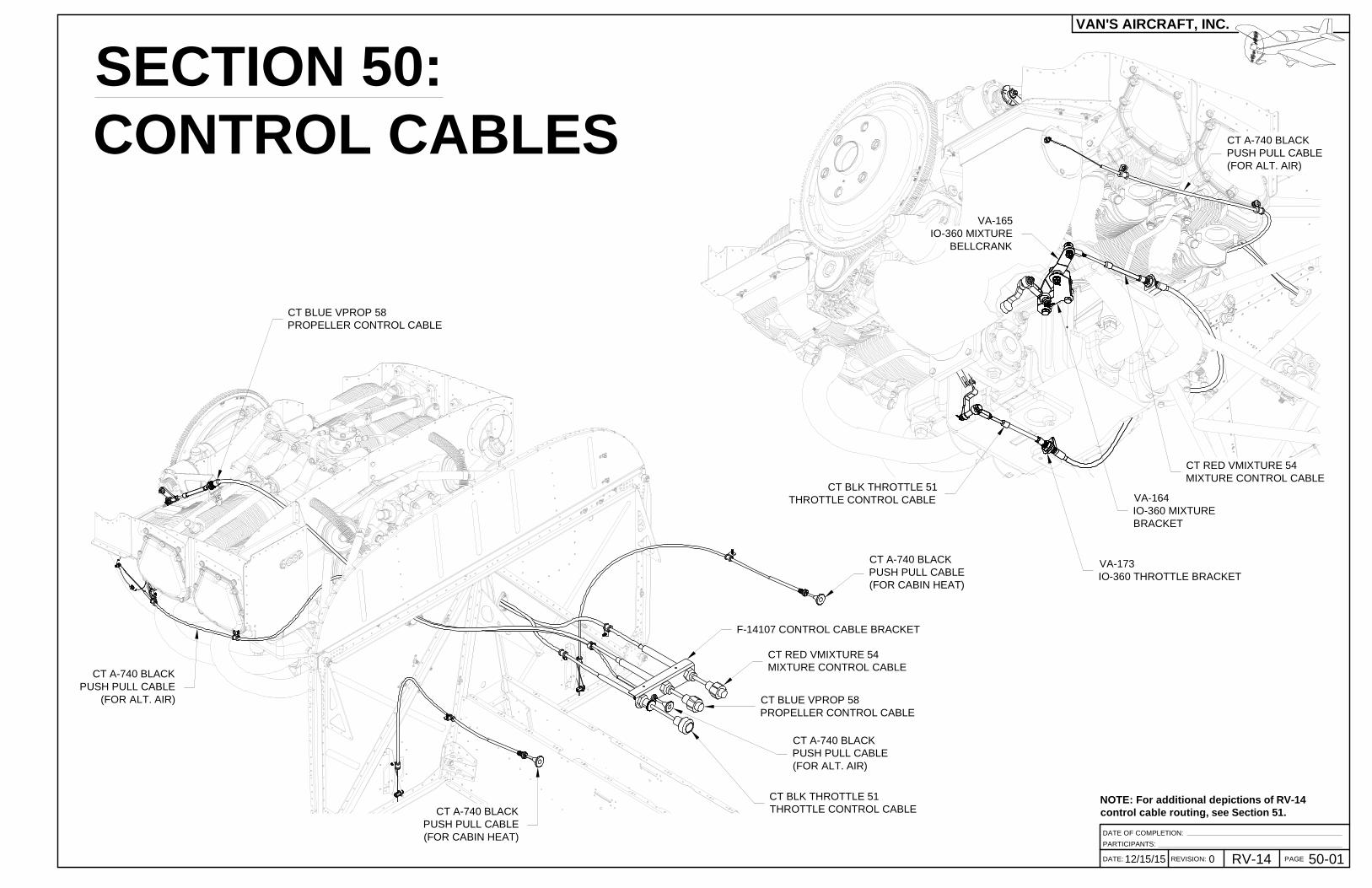
SECTION 50:CONTROL CABLES
PARTICIPANTS:
12/15/15 0 RV-14
DATE OF COMPLETION:
50-01
CT A-740 BLACKPUSH PULL CABLE(FOR CABIN HEAT)
CT A-740 BLACKPUSH PULL CABLE(FOR CABIN HEAT)
CT RED VMIXTURE 54MIXTURE CONTROL CABLE
CT BLUE VPROP 58PROPELLER CONTROL CABLE
CT A-740 BLACKPUSH PULL CABLE(FOR ALT. AIR)
CT BLK THROTTLE 51THROTTLE CONTROL CABLE
CT BLK THROTTLE 51THROTTLE CONTROL CABLE
CT RED VMIXTURE 54MIXTURE CONTROL CABLE
VA-164IO-360 MIXTUREBRACKET
VA-165IO-360 MIXTURE
BELLCRANK
F-14107 CONTROL CABLE BRACKET
VA-173IO-360 THROTTLE BRACKET
CT A-740 BLACKPUSH PULL CABLE(FOR ALT. AIR)
CT BLUE VPROP 58PROPELLER CONTROL CABLE
CT A-740 BLACKPUSH PULL CABLE
(FOR ALT. AIR)
NOTE: For additional depictions of RV-14control cable routing, see Section 51.

PAGE REVISION: DATE:
VAN'S AIRCRAFT, INC.
12/15/15PAGE 50-02 RV-14 REVISION: 0 DATE:
NOTE: For all control cable installations, there are two VITAL CRITERIA:
1. When the control knob is pulled out half way, the arm must also be at the halfway pointbetween the "open" and "closed" control stops. This will ensure smooth and consistentinputs along the entire range of control motion.
2. When the control knob is in the full forward position, and the arm travel has beenstopped by the control stop, a 1/16 in. [1.6 mm] "cushion gap" remains. This willensure that the full travel of the arm is available and not limited by the control cable.
Step 1: Install the F-014107 Control Cable Bracket on to the F-01467 Instrument PanelFrame as shown in the right detail view in Figure 2.
Step 2: Remove all nuts, lock washers and rubber seals from the CT BLK THROTTLE 51Throttle Control Cable, CT RED VMIXTURE 54 Mixture Control Cable,CT BLUE VPROP 58 Propeller Control Cable , and the threeCT A-740 Black Push Pull Cables.
Step 3: Pull the knobs of the CT A-740 Black Push Pull Cables (For Cabin Heat) outuntil there is large (greater than 3 in. [76.2 mm]) gap between the knobs and theshanks. See Figure 1.
Step 4: Use a die grinder to trim the cabin heat housings and wires to the lengthcalled out in Figure 1.
CT A-740 BLACK(FOR CABIN HEAT),
2 PL
AN52510R7 MS21919DG3 INSTALLED IN F-01455, BOTH SIDES
CT BLUEVPROP 58
CT A-740(FOR ALT.AIR)
CT BLACK PROP 51
SB625-8, SLIT SIDEAND INSTALL AROUND
CT A-740 & CT BLUE VPROP 58
AN52510R7MS21919DG5,BOTH SIDES
OF F-14106
2X
F-01467
F-14106
F-14107
AN525-832R8NAS1149FN832P
LARGE BEND RADII ON ALLCONTROL CABLES TO
ENSURE SMOOTH OPERATION, TYP
PLASTIC TIE WRAP, 4",3 PL
TIGHTEN SET SCREW
NAS1149F0332P AN320-3 MS24665-132
AN515-8R8
MS21919DG3
MS21042-08
2X NAS1149F0332P
VA-181-1
F-01467
CT REDVMIXTURE 54
CABIN HEAT DOOR
SHANK
Step 5: Push the knobs of the cabin heat cables in until the "cushion gap"remains between the knob and shank. See Figure 1.
Step 6: Close the cabin heat doors.
Step 7: Install the cabin heat cables as shown in the left detail view in Figure 2.
Step 8: Install, route, and loosely secure the throttle, mixture, propeller,and alt. air control cables as shown. Leave the tie wraps, clamps, andthe ends of the cables loose for now.
NUT & LOCK WASHER(SUPPLIED WITH CONTROL CABLE),
TYP FOR ALL CONTROL CABLES
F-01467
1/16 [1.6 mm]CUSHION
GAP
FF-00001
FF-00001
HOUSING
WIRE
TRIM
WIRE
HOUSINGKNOB
36 [914.4 mm]
FIGURE 1: CABIN HEAT CABLE
FIGURE 2: CONTROLCABLE ROUTING
(AFT OF FIREWALL)
3 MIN[76.2 mm] GAP

NUT ANDLOCK WASHER(PROVIDEDWITH CONTROLCABLE)
PAGEREVISION:DATE:
VAN'S AIRCRAFT, INC.
DATE: 50-03012/15/15 REVISION: RV-14 PAGE
MW-3M
AN310-3
5702-475-48 Z3
2X 5702-75-60
AN3-10
2X
Step 1: Install the snap bushing into the CB-00017 Left Aft Baffle as shown in Figure 2.
Step 2: Route and install the propeller control cable as shown in Figure 1 and Figure 2.Ensure the propeller control cable installation meets the vital criteria listed onPage 50-02. See Page 43-07 for more information on adjusting the propellergovernor arm and faceplate.
Step 3: Install the mixture control cable as shown in Figure 1, Figure 3 andSection OP-22, Ensure the mixture control cable installation meets the vitalcriteria listed on Page 50-02. If necessary, a djust the clocking of themixture arm.
PROPELLERGOVERNORBRACKETASSEMBLY
MS24665-132
UP
FWD LEFT
FIGURE 2: PROPELLER CABLE INSTALLATION
GOVERNORARM
VA-163(INSTALLED ON ENGINE)
MIXTURE ARM (ON ENGINE)
FIGURE 3: MIXTURE CONTROLCABLE INSTALLATION
CT RED VMIXTURE 54
VA-165
VA-164(INSTALLED ON ENGINE)
POT WITH RTV HIGHTEMP. SEALANT
ADJUST NUTS & LOCK WASHERS
MAX 7 THREADS EXPOSED
MAX 7THREADSEXPOSED
CT BLUEVPROP 58
ADJUST NUTS & LOCK WASHERS
CB-00017
RE-INSTALL RUBBERFITTING
RE-INSTALL RUBBERFITTING
RE-INSTALL RUBBERFITTING
UP
FWD
RE-INSTALL RUBBERFITTINGS
NAS1149F0363P
SB625-8
1/16 [1.6 mm]CUSHION GAP
KNOB
SHANK
FIGURE 1: CONTROL CABLE, TYPICAL
F-14107
PAGE REVISION: DATE:
VAN'S AIRCRAFT, INC.
12/15/1550-04 RV-14 REVISION:REVISION: 0 DATE:DATE:
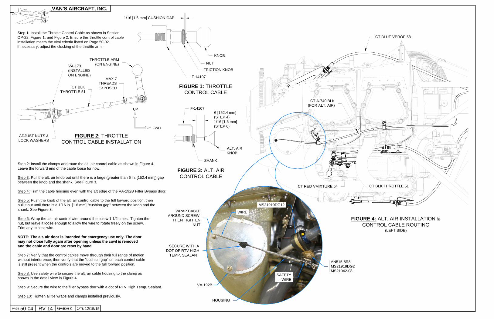
Step 1: Install the Throttle Control Cable as shown in SectionOP-22, Figure 1, and Figure 2. Ensure the throttle control cableinstallation meets the vital criteria listed on Page 50-02.If necessary, adjust the clocking of the throttle arm.
1/16 [1.6 mm] CUSHION GAP
F-14107
KNOB
FRICTION KNOB
NUT
CT BLKTHROTTLE 51
THROTTLE ARM(ON ENGINE)VA-173
(INSTALLEDON ENGINE)
Step 2: Install the clamps and route the alt. air control cable as shown in Figure 4.Leave the forward end of the cable loose for now.
Step 3: Pull the alt. air knob out until there is a large (greater than 6 in. [152.4 mm]) gapbetween the knob and the shank. See Figure 3.
Step 4: Trim the cable housing even with the aft edge of the VA-192B Filter Bypass door.
Step 5: Push the knob of the alt. air control cable to the full forward position, thenpull it out until there is a 1/16 in. [1.6 mm] "cushion gap" between the knob and theshank. See Figure 3.
Step 6: Wrap the alt. air control wire around the screw 1 1/2 times. Tighten thenut, but leave it loose enough to allow the wire to rotate freely on the screw.Trim any excess wire.
NOTE: The alt. air door is intended for emergency use only. The doormay not close fully again after opening unless the cowl is removedand the cable and door are reset by hand.
Step 7: Verify that the control cables move through their full range of motionwithout interference, then verify that the "cushion gap" on each control cableis still present when the controls are moved to the full forward position.
Step 8: Use safety wire to secure the alt. air cable housing to the clamp asshown in the detail view in Figure 4.
Step 9: Secure the wire to the filler bypass dorr with a dot of RTV High Temp. Sealant.
Step 10: Tighten all tie wraps and clamps installed previously.
CT RED VMIXTURE 54 CT BLK THROTTLE 51
CT BLUE VPROP 58
CT A-740 BLK(FOR ALT. AIR)
ADJUST NUTS &LOCK WASHERS
MAX 7THREADSEXPOSED
SECURE WITH ADOT OF RTV HIGH
TEMP. SEALANT
WIRE
HOUSING
VA-192B
SAFETYWIRE
WRAP CABLEAROUND SCREW,
THEN TIGHTENNUT
FIGURE 1: THROTTLECONTROL CABLE
ALT. AIRKNOB
SHANK
F-14107
FIGURE 3: ALT. AIRCONTROL CABLE
6 [152.4 mm](STEP 4)1/16 [1.6 mm](STEP 6)
UP
FWD
FIGURE 4: ALT. AIR INSTALLATION &CONTROL CABLE ROUTING
(LEFT SIDE)
MS21919DG12
AN515-8R8 MS21919DG2 MS21042-08
FIGURE 2: THROTTLECONTROL CABLE INSTALLATION