section 5.0
TRANSCRIPT
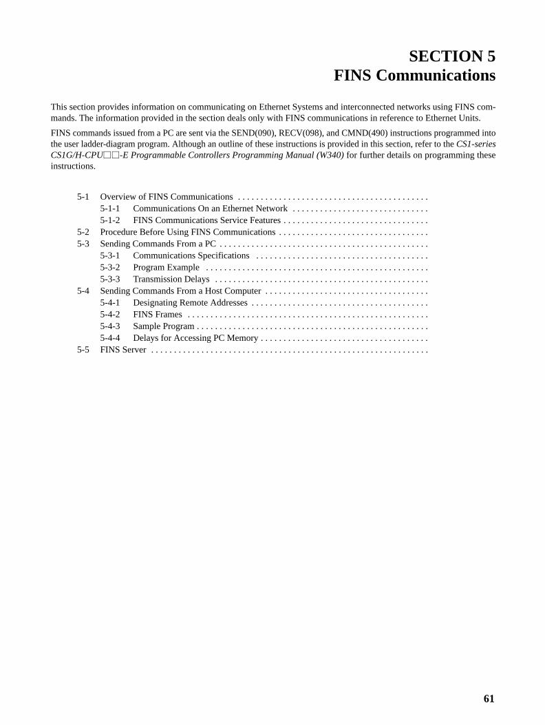
61
SECTION 5FINS Communications
This section provides information on communicating on Ethernet Systems and interconnected networks using FINS com-mands. The information provided in the section deals only with FINS communications in reference to Ethernet Units.
FINS commands issued from a PC are sent via the SEND(090), RECV(098), and CMND(490) instructions programmed intothe user ladder-diagram program. Although an outline of these instructions is provided in this section, refer to the CS1-seriesCS1G/H-CPU��-E Programmable Controllers Programming Manual (W340) for further details on programming theseinstructions.
5-1 Overview of FINS Communications . . . . . . . . . . . . . . . . . . . . . . . . . . . . . . . . . . . . . . . . . . 5-1-1 Communications On an Ethernet Network . . . . . . . . . . . . . . . . . . . . . . . . . . . . . . 5-1-2 FINS Communications Service Features . . . . . . . . . . . . . . . . . . . . . . . . . . . . . . . .
5-2 Procedure Before Using FINS Communications . . . . . . . . . . . . . . . . . . . . . . . . . . . . . . . . . 5-3 Sending Commands From a PC . . . . . . . . . . . . . . . . . . . . . . . . . . . . . . . . . . . . . . . . . . . . . .
5-3-1 Communications Specifications . . . . . . . . . . . . . . . . . . . . . . . . . . . . . . . . . . . . . . 5-3-2 Program Example . . . . . . . . . . . . . . . . . . . . . . . . . . . . . . . . . . . . . . . . . . . . . . . . . 5-3-3 Transmission Delays . . . . . . . . . . . . . . . . . . . . . . . . . . . . . . . . . . . . . . . . . . . . . . .
5-4 Sending Commands From a Host Computer . . . . . . . . . . . . . . . . . . . . . . . . . . . . . . . . . . . . 5-4-1 Designating Remote Addresses . . . . . . . . . . . . . . . . . . . . . . . . . . . . . . . . . . . . . . . 5-4-2 FINS Frames . . . . . . . . . . . . . . . . . . . . . . . . . . . . . . . . . . . . . . . . . . . . . . . . . . . . . 5-4-3 Sample Program . . . . . . . . . . . . . . . . . . . . . . . . . . . . . . . . . . . . . . . . . . . . . . . . . . . 5-4-4 Delays for Accessing PC Memory . . . . . . . . . . . . . . . . . . . . . . . . . . . . . . . . . . . . .
5-5 FINS Server . . . . . . . . . . . . . . . . . . . . . . . . . . . . . . . . . . . . . . . . . . . . . . . . . . . . . . . . . . . . .
5-1SectionOverview of FINS Communications
62
5-1 Overview of FINS CommunicationsThe FINS communications service enables client control of operations such asreading or writing server PC memory area data without the need to programthese operations into the server PC user program. The Ethernet Unit uses a ded-icated UDP/IP port to execute the FINS communications service. (Refer to FINSUDP Port Number under 4-2-1 Settings.)
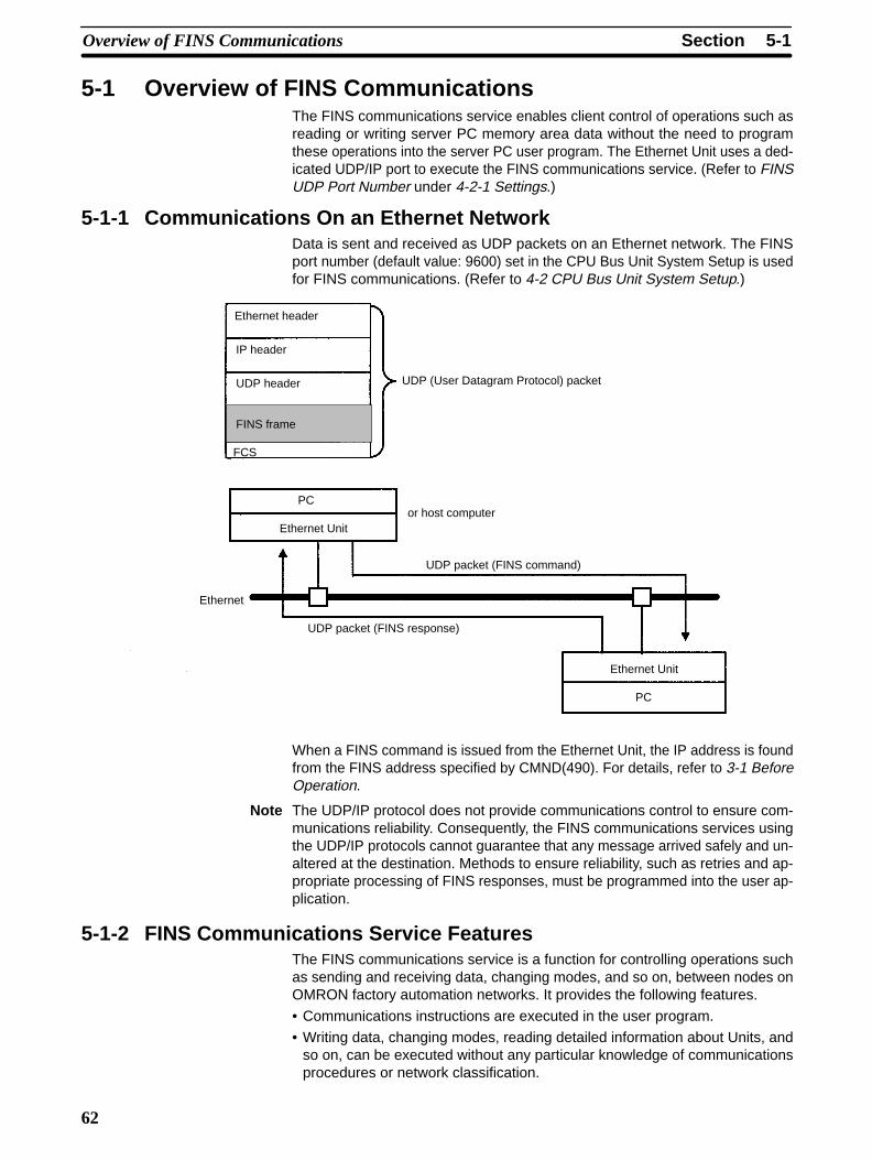
5-1-1 Communications On an Ethernet NetworkData is sent and received as UDP packets on an Ethernet network. The FINSport number (default value: 9600) set in the CPU Bus Unit System Setup is usedfor FINS communications. (Refer to 4-2 CPU Bus Unit System Setup.)
Ethernet header
IP header
UDP header
FCS
UDP (User Datagram Protocol) packet
PC
Ethernet Unitor host computer
UDP packet (FINS command)
Ethernet
UDP packet (FINS response)
Ethernet Unit
PC
FINS frame
When a FINS command is issued from the Ethernet Unit, the IP address is foundfrom the FINS address specified by CMND(490). For details, refer to 3-1 BeforeOperation.
Note The UDP/IP protocol does not provide communications control to ensure com-munications reliability. Consequently, the FINS communications services usingthe UDP/IP protocols cannot guarantee that any message arrived safely and un-altered at the destination. Methods to ensure reliability, such as retries and ap-propriate processing of FINS responses, must be programmed into the user ap-plication.
5-1-2 FINS Communications Service FeaturesThe FINS communications service is a function for controlling operations suchas sending and receiving data, changing modes, and so on, between nodes onOMRON factory automation networks. It provides the following features.
• Communications instructions are executed in the user program.
• Writing data, changing modes, reading detailed information about Units, andso on, can be executed without any particular knowledge of communicationsprocedures or network classification.
5-1SectionOverview of FINS Communications
63
• Units and Boards that support FINS commands return responses automatical-ly, so there is no need for a program at the receiving end.
• The FINS communications service is mainly used between OMRON CPU BusUnits, CPU Units, and Support Boards for FA Computers. By correctly settinginformation such as headers, however, it can also be used from ordinary Ether-net communications devices.
The FINS communications service can be used from a PC with either of the fol-lowing three instructions:
• SEND(090)/RECV(098)
SEND(090) and RECV(098) are used to send and receive data (area read-ing and writing).
• CMND(490)
CMND(490) is used to send FINS commands. The particular FINS com-mands that are supported vary depending of the type of Unit or Board. Fordetails on FINS commands addressed to Ethernet Units, refer to Section 11FINS Commands Addressed to Ethernet Units. For details regarding FINScommands addressed to CS1-series CPU Units, refer to the CS1-seriesCS1G/H-CPU��-E Programmable Controllers Communications Com-mands Reference Manual (W342).
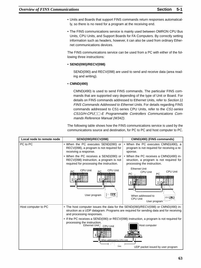
The following table shows how the FINS communications service is used by thecommunications source and destination, for PC to PC and host computer to PC.
Local node to remote node SEND(090)/RECV(098) CMND(490) (FINS commands)
PC to PC • When the PC executes SEND(090) orRECV(098), a program is not required forreceiving a response.
• When the PC receives a SEND(090) orRECV(098) instruction, a program is notrequired for processing the instruction.
CPU Unit CPU Unit
User program
PC PC
• When the PC executes CMND(490), aprogram is not required for receiving a re-sponse.
• When the PC receives a CMND(490) in-struction, a program is not required forprocessing the instruction.
Ethernet UnitCPU Unit CPU Unit
When addressed toCPU Unit
User program
PC PC
Host computer to PC • The host computer issues the data for the SEND(090)/RECV(098) or CMND(490) in-struction as a UDP datagram. Programs are required for sending data and for receivingand processing responses.
• If the PC receives a SEND(090) or RECV(098) instruction, a program is not required forprocessing the instruction.
Ethernet Unit CPU Unit
When addressed to CPU Unit
Host computer
UDP packet issued by user programData
5-2SectionProcedure Before Using FINS Communications
64
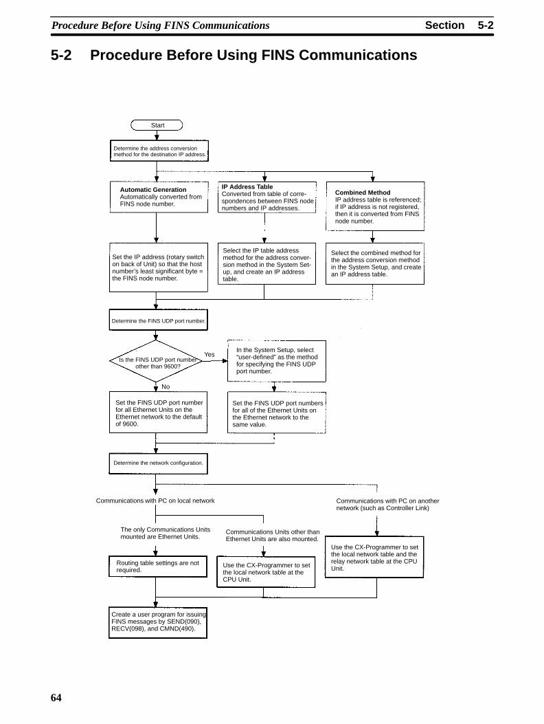
5-2 Procedure Before Using FINS Communications
Start
Determine the address conversionmethod for the destination IP address.
Automatic GenerationAutomatically converted fromFINS node number.
IP Address T ableConverted from table of corre-spondences between FINS nodenumbers and IP addresses.
Combined MethodIP address table is referenced;if IP address is not registered,then it is converted from FINSnode number.
Set the IP address (rotary switchon back of Unit) so that the hostnumber’s least significant byte =the FINS node number.
Select the IP table addressmethod for the address conver-sion method in the System Set-up, and create an IP addresstable.
Select the combined method forthe address conversion methodin the System Setup, and createan IP address table.
Determine the FINS UDP port number.
Is the FINS UDP port numberother than 9600?
Yes
No
In the System Setup, select“user-defined” as the methodfor specifying the FINS UDPport number.
Set the FINS UDP port numberfor all Ethernet Units on theEthernet network to the defaultof 9600.
Set the FINS UDP port numbersfor all of the Ethernet Units onthe Ethernet network to thesame value.
Determine the network configuration.
Communications with PC on local network Communications with PC on anothernetwork (such as Controller Link)
The only Communications Unitsmounted are Ethernet Units.
Communications Units other thanEthernet Units are also mounted.
Routing table settings are notrequired.
Use the CX-Programmer to setthe local network table at theCPU Unit.
Use the CX-Programmer to setthe local network table and therelay network table at the CPUUnit.
Create a user program for issuingFINS messages by SEND(090),RECV(098), and CMND(490).
5-3SectionSending Commands From a PC
65
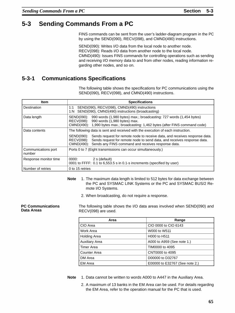
5-3 Sending Commands From a PC
FINS commands can be sent from the user’s ladder-diagram program in the PCby using the SEND(090), RECV(098), and CMND(490) instructions.
SEND(090): Writes I/O data from the local node to another node.RECV(098): Reads I/O data from another node to the local node.CMND(490): Issues FINS commands for controlling operations such as sendingand receiving I/O memory data to and from other nodes, reading information re-garding other nodes, and so on.
5-3-1 Communications Specifications
The following table shows the specifications for PC communications using theSEND(090), RECV(098), and CMND(490) instructions.
Item Specifications
Destination 1:1 SEND(090), RECV(098), CMND(490) instructions1:N SEND(090), CMND(490) instructions (broadcasting)
Data length SEND(090): 990 words (1,980 bytes) max.; broadcasting: 727 words (1,454 bytes)RECV(098): 990 words (1,980 bytes) max.CMND(490): 1,990 bytes max.; broadcasting: 1,462 bytes (after FINS command code)
Data contents The following data is sent and received with the execution of each instruction.
SEND(090): Sends request for remote node to receive data, and receives response data.RECV(098): Sends request for remote node to send data, and receives response data.CMND(490): Sends any FINS command and receives response data.
Communications portnumber
Ports 0 to 7 (Eight transmissions can occur simultaneously.)
Response monitor time 0000: 2 s (default)0001 to FFFF: 0.1 to 6,553.5 s in 0.1-s increments (specified by user)
Number of retries 0 to 15 retries
Note 1. The maximum data length is limited to 512 bytes for data exchange betweenthe PC and SYSMAC LINK Systems or the PC and SYSMAC BUS/2 Re-mote I/O Systems.
2. When broadcasting, do not require a response.
The following table shows the I/O data areas involved when SEND(090) andRECV(098) are used.
Area Range
CIO Area CIO 0000 to CIO 6143
Work Area W000 to W511
Holding Area H000 to H511
Auxiliary Area A000 to A959 (See note 1.)
Timer Area TIM0000 to 4095
Counter Area CNT0000 to 4095
DM Area D00000 to D32767
EM Area E00000 to E32767 (See note 2.)
Note 1. Data cannot be written to words A000 to A447 in the Auxiliary Area.
2. A maximum of 13 banks in the EM Area can be used. For details regardingthe EM Area, refer to the operation manual for the PC that is used.
PC CommunicationsData Areas
5-3SectionSending Commands From a PC
66
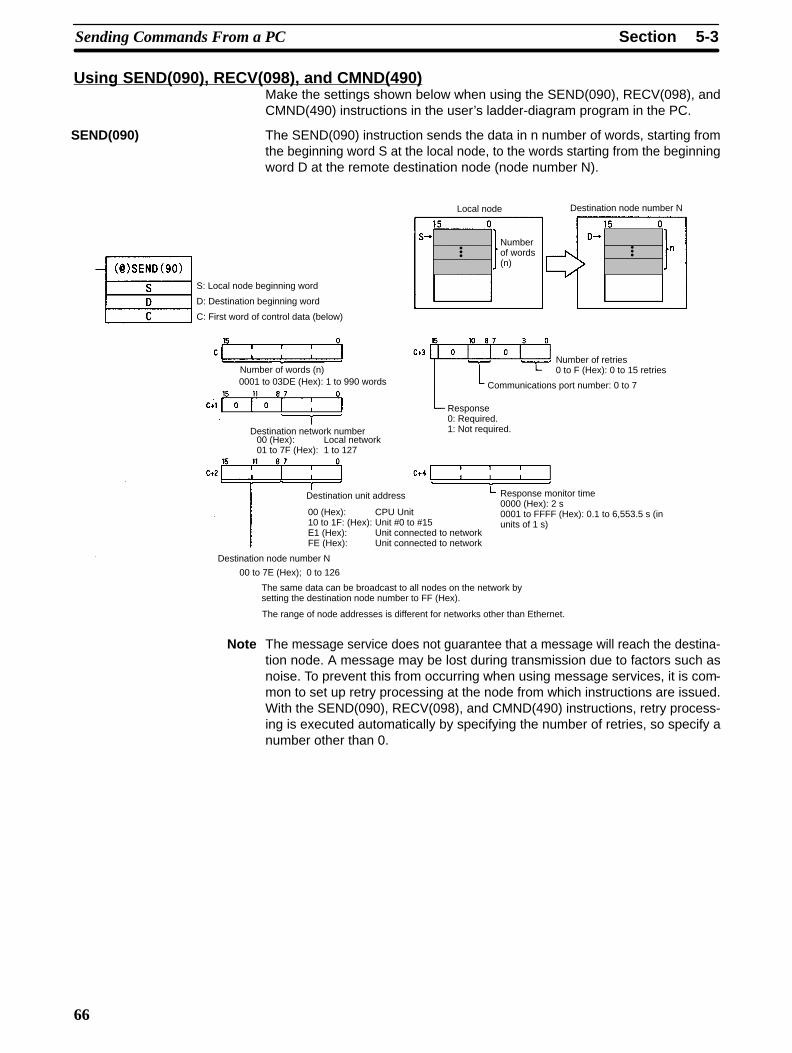
Using SEND(090), RECV(098), and CMND(490)Make the settings shown below when using the SEND(090), RECV(098), andCMND(490) instructions in the user’s ladder-diagram program in the PC.
The SEND(090) instruction sends the data in n number of words, starting fromthe beginning word S at the local node, to the words starting from the beginningword D at the remote destination node (node number N).
S: Local node beginning word
D: Destination beginning word
C: First word of control data (below)
Local node
Numberof words(n)
Destination node number N
Number of words (n)0001 to 03DE (Hex): 1 to 990 words
Destination network number00 (Hex): Local network01 to 7F (Hex): 1 to 127
Destination unit address
00 (Hex): CPU Unit10 to 1F: (Hex): Unit #0 to #15E1 (Hex): Unit connected to networkFE (Hex): Unit connected to network
Destination node number N
00 to 7E (Hex); 0 to 126
The same data can be broadcast to all nodes on the network bysetting the destination node number to FF (Hex).
The range of node addresses is different for networks other than Ethernet.
Number of retries0 to F (Hex): 0 to 15 retries
Communications port number: 0 to 7
Response0: Required.1: Not required.
Response monitor time0000 (Hex): 2 s0001 to FFFF (Hex): 0.1 to 6,553.5 s (inunits of 1 s)
���
���
Note The message service does not guarantee that a message will reach the destina-tion node. A message may be lost during transmission due to factors such asnoise. To prevent this from occurring when using message services, it is com-mon to set up retry processing at the node from which instructions are issued.With the SEND(090), RECV(098), and CMND(490) instructions, retry process-ing is executed automatically by specifying the number of retries, so specify anumber other than 0.
SEND(090)
5-3SectionSending Commands From a PC
67
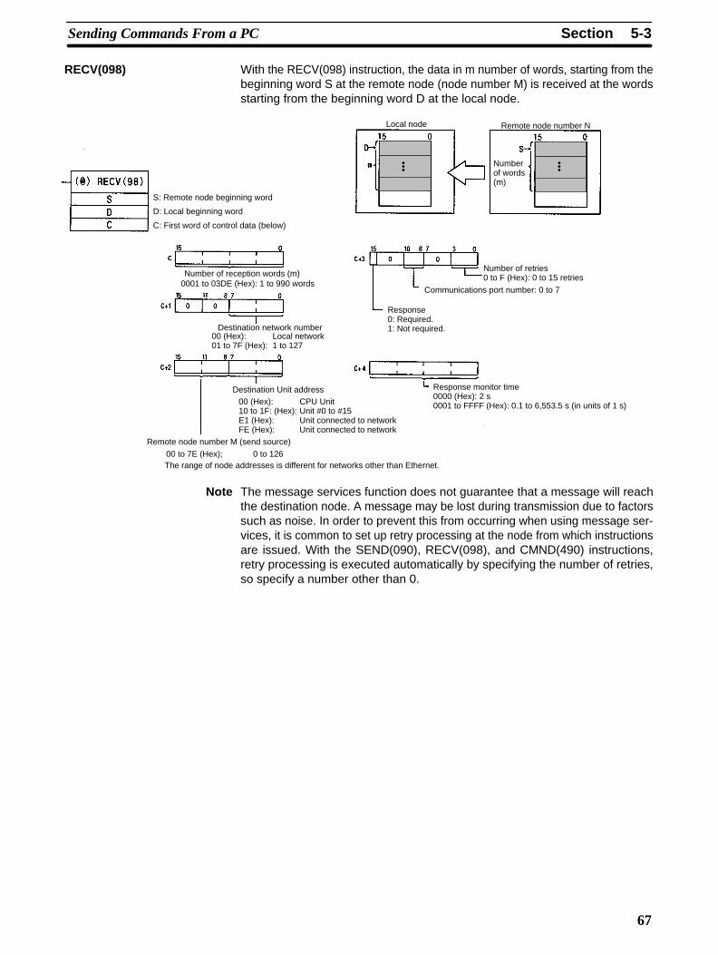
With the RECV(098) instruction, the data in m number of words, starting from thebeginning word S at the remote node (node number M) is received at the wordsstarting from the beginning word D at the local node.
S: Remote node beginning word
D: Local beginning word
C: First word of control data (below)
Local node
Numberof words(m)
Remote node number N
Number of reception words (m)0001 to 03DE (Hex): 1 to 990 words
Destination network number00 (Hex): Local network01 to 7F (Hex): 1 to 127
Destination Unit address00 (Hex): CPU Unit10 to 1F: (Hex): Unit #0 to #15E1 (Hex): Unit connected to networkFE (Hex): Unit connected to network
Remote node number M (send source)00 to 7E (Hex); 0 to 126The range of node addresses is different for networks other than Ethernet.
Number of retries0 to F (Hex): 0 to 15 retries
Communications port number: 0 to 7
Response0: Required.1: Not required.
Response monitor time0000 (Hex): 2 s0001 to FFFF (Hex): 0.1 to 6,553.5 s (in units of 1 s)
���
���
Note The message services function does not guarantee that a message will reachthe destination node. A message may be lost during transmission due to factorssuch as noise. In order to prevent this from occurring when using message ser-vices, it is common to set up retry processing at the node from which instructionsare issued. With the SEND(090), RECV(098), and CMND(490) instructions,retry processing is executed automatically by specifying the number of retries,so specify a number other than 0.
RECV(098)
5-3SectionSending Commands From a PC
68
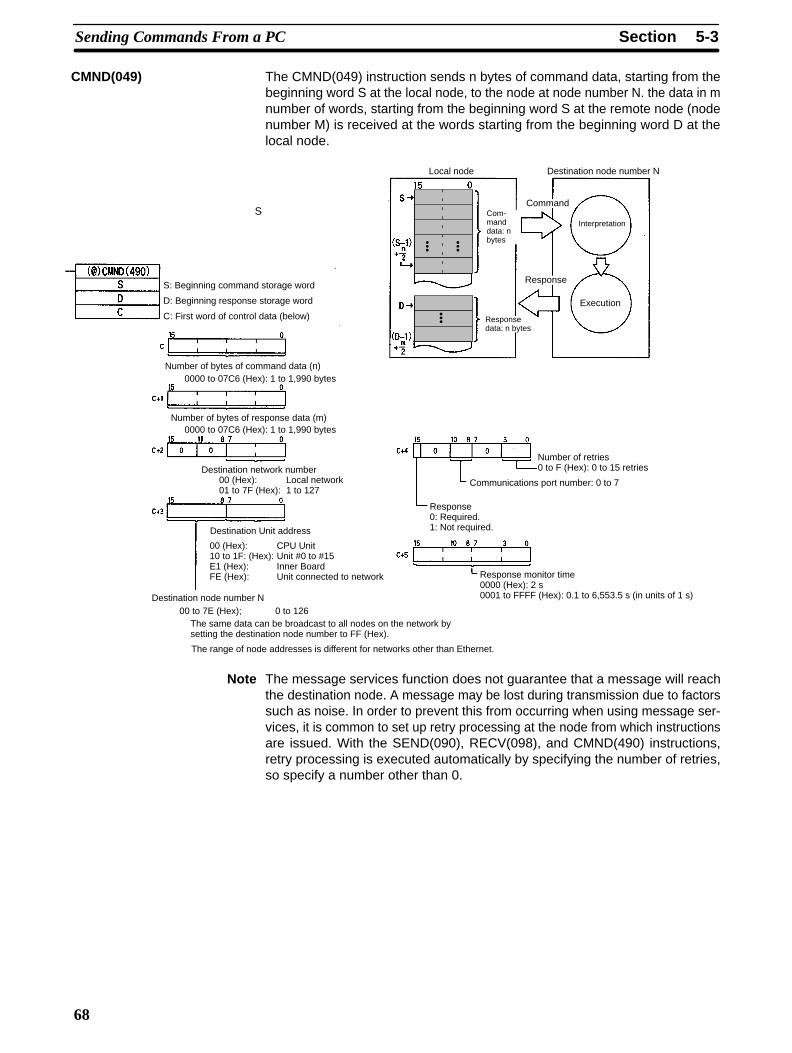
The CMND(049) instruction sends n bytes of command data, starting from thebeginning word S at the local node, to the node at node number N. the data in mnumber of words, starting from the beginning word S at the remote node (nodenumber M) is received at the words starting from the beginning word D at thelocal node.
S: Beginning command storage word
D: Beginning response storage word
C: First word of control data (below)
Local node Destination node number N
Number of bytes of command data (n)0000 to 07C6 (Hex): 1 to 1,990 bytes
Number of bytes of response data (m)
00 (Hex): Local network01 to 7F (Hex): 1 to 127
Destination Unit address
00 (Hex): CPU Unit10 to 1F: (Hex): Unit #0 to #15E1 (Hex): Inner BoardFE (Hex): Unit connected to network
Destination node number N00 to 7E (Hex); 0 to 126
The same data can be broadcast to all nodes on the network bysetting the destination node number to FF (Hex).
The range of node addresses is different for networks other than Ethernet.
Number of retries0 to F (Hex): 0 to 15 retries
Communications port number: 0 to 7
Response0: Required.1: Not required.
Response monitor time0000 (Hex): 2 s0001 to FFFF (Hex): 0.1 to 6,553.5 s (in units of 1 s)
0000 to 07C6 (Hex): 1 to 1,990 bytes
Destination network number
Com-manddata: nbytes
Responsedata: n bytes
Command
Response
Interpretation
Execution
S
���
���
���
Note The message services function does not guarantee that a message will reachthe destination node. A message may be lost during transmission due to factorssuch as noise. In order to prevent this from occurring when using message ser-vices, it is common to set up retry processing at the node from which instructionsare issued. With the SEND(090), RECV(098), and CMND(490) instructions,retry processing is executed automatically by specifying the number of retries,so specify a number other than 0.
CMND(049)
5-3SectionSending Commands From a PC
69
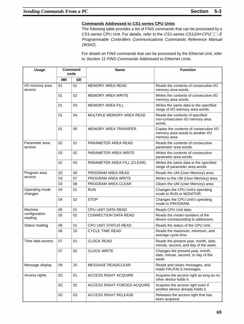
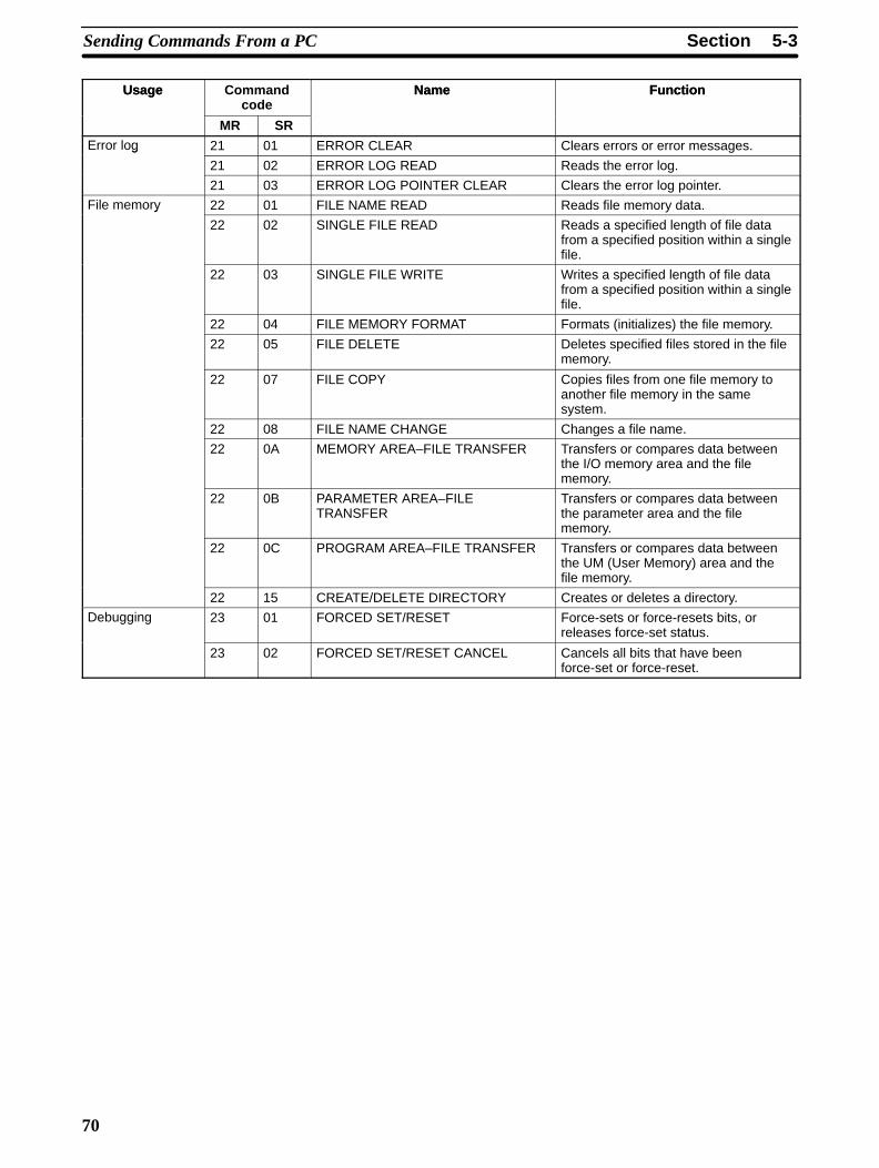
Commands Addressed to CS1-series CPU UnitsThe following table provides a list of FINS commands that can be processed by aCS1-series CPU Unit. For details, refer to the CS1-series CS1G/H-CPU��-EProgrammable Controllers Communications Commands Reference Manual(W342).
For details on FINS commands that can be processed by the Ethernet Unit, referto Section 11 FINS Commands Addressed to Ethernet Units.
Usage Commandcode
Name Function
MR SR
I/O memory areaaccess
01 01 MEMORY AREA READ Reads the contents of consecutive I/Omemory area words.
01 02 MEMORY AREA WRITE Writes the contents of consecutive I/Omemory area words.
01 03 MEMORY AREA FILL Writes the same data to the specifiedrange of I/O memory area words.
01 04 MULTIPLE MEMORY AREA READ Reads the contents of specifiednon-consecutive I/O memory areawords.
01 05 MEMORY AREA TRANSFER Copies the contents of consecutive I/Omemory area words to another I/Omemory area.
Parameter areaaccess
02 01 PARAMETER AREA READ Reads the contents of consecutiveparameter area words.
02 02 PARAMETER AREA WRITE Writes the contents of consecutiveparameter area words.
02 03 PARAMETER AREA FILL (CLEAR) Writes the same data to the specifiedrange of parameter area words.
Program area 03 06 PROGRAM AREA READ Reads the UM (User Memory) area.gaccess 03 07 PROGRAM AREA WRITE Writes to the UM (User Memory) area.
03 08 PROGRAM AREA CLEAR Clears the UM (User Memory) area.
Operating modechanges
04 01 RUN Changes the CPU Unit’s operatingmode to RUN or MONITOR.g
04 02 STOP Changes the CPU Unit’s operatingmode to PROGRAM.
Machinefi i
05 01 CPU UNIT DATA READ Reads CPU Unit data.configurationreading
05 02 CONNECTION DATA READ Reads the model numbers of thedevice corresponding to addresses.
Status reading 06 01 CPU UNIT STATUS READ Reads the status of the CPU Unit.g
06 20 CYCLE TIME READ Reads the maximum, minimum, andaverage cycle time.
Time data access 07 01 CLOCK READ Reads the present year, month, date,minute, second, and day of the week.
07 02 CLOCK WRITE Changes the present year, month,date, minute, second, or day of theweek.
Message display 09 20 MESSAGE READ/CLEAR Reads and clears messages, andreads FAL/FALS messages.
Access rights 0C 01 ACCESS RIGHT ACQUIRE Acquires the access right as long as noother device holds it.
0C 02 ACCESS RIGHT FORCED ACQUIRE Acquires the access right even ifanother device already holds it.
0C 03 ACCESS RIGHT RELEASE Releases the access right that hasbeen acquired.
5-3SectionSending Commands From a PC
70
Usage FunctionNameCommandcode
Usage FunctionName
SRMRError log 21 01 ERROR CLEAR Clears errors or error messages.g
21 02 ERROR LOG READ Reads the error log.
21 03 ERROR LOG POINTER CLEAR Clears the error log pointer.
File memory 22 01 FILE NAME READ Reads file memory data.y
22 02 SINGLE FILE READ Reads a specified length of file datafrom a specified position within a singlefile.
22 03 SINGLE FILE WRITE Writes a specified length of file datafrom a specified position within a singlefile.
22 04 FILE MEMORY FORMAT Formats (initializes) the file memory.
22 05 FILE DELETE Deletes specified files stored in the filememory.
22 07 FILE COPY Copies files from one file memory toanother file memory in the samesystem.
22 08 FILE NAME CHANGE Changes a file name.
22 0A MEMORY AREA–FILE TRANSFER Transfers or compares data betweenthe I/O memory area and the filememory.
22 0B PARAMETER AREA–FILETRANSFER
Transfers or compares data betweenthe parameter area and the filememory.
22 0C PROGRAM AREA–FILE TRANSFER Transfers or compares data betweenthe UM (User Memory) area and thefile memory.
22 15 CREATE/DELETE DIRECTORY Creates or deletes a directory.
Debugging 23 01 FORCED SET/RESET Force-sets or force-resets bits, orreleases force-set status.
23 02 FORCED SET/RESET CANCEL Cancels all bits that have beenforce-set or force-reset.
5-3SectionSending Commands From a PC
71
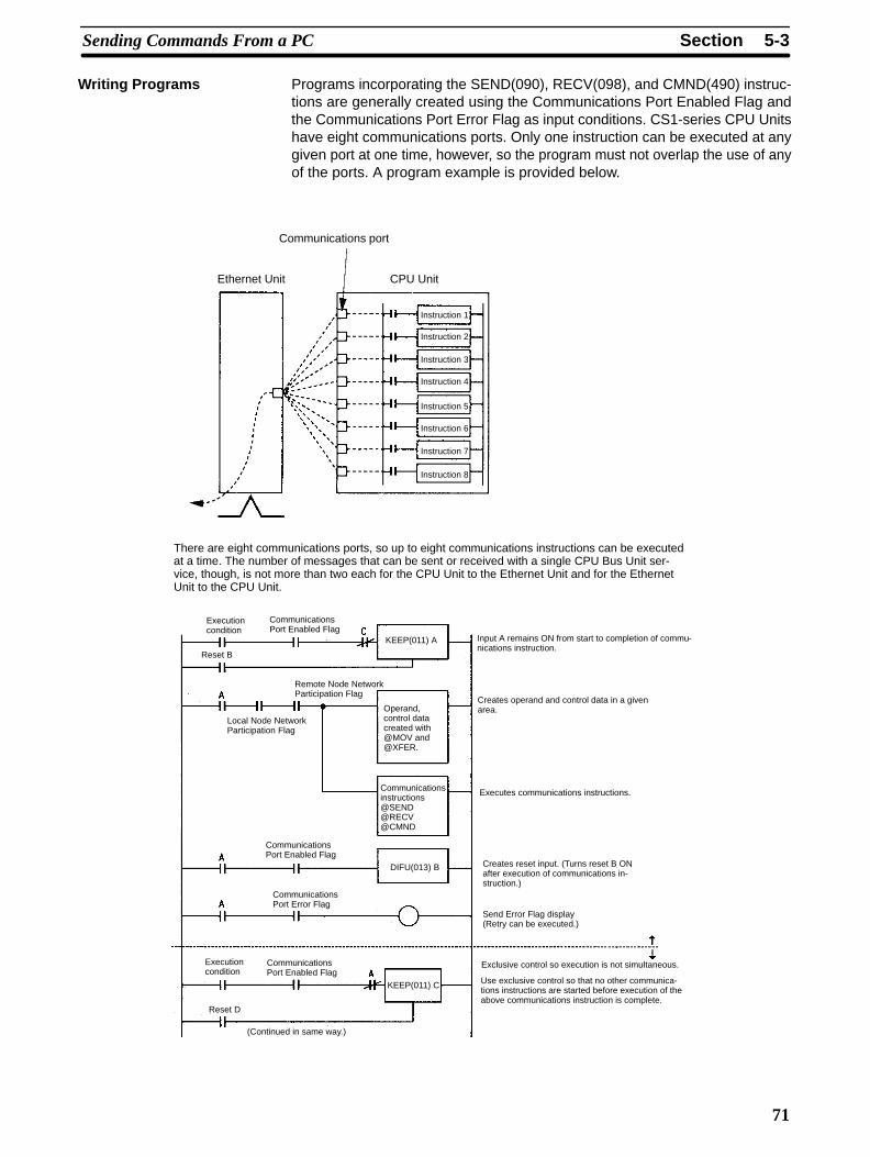
Programs incorporating the SEND(090), RECV(098), and CMND(490) instruc-tions are generally created using the Communications Port Enabled Flag andthe Communications Port Error Flag as input conditions. CS1-series CPU Unitshave eight communications ports. Only one instruction can be executed at anygiven port at one time, however, so the program must not overlap the use of anyof the ports. A program example is provided below.
Communications port
Ethernet Unit CPU Unit
There are eight communications ports, so up to eight communications instructions can be executedat a time. The number of messages that can be sent or received with a single CPU Bus Unit ser-vice, though, is not more than two each for the CPU Unit to the Ethernet Unit and for the EthernetUnit to the CPU Unit.
Execution condition
CommunicationsPort Enabled Flag
KEEP(011) A
Reset B
Input A remains ON from start to completion of commu-nications instruction.
Local Node NetworkParticipation Flag
Operand,control datacreated with@MOV and@XFER.
Creates operand and control data in a givenarea.
CommunicationsPort Enabled Flag
DIFU(013) B
Executes communications instructions.
CommunicationsPort Error Flag
Reset D
CommunicationsPort Enabled Flag
KEEP(011) C
Creates reset input. (Turns reset B ONafter execution of communications in-struction.)
Exclusive control so execution is not simultaneous.
Use exclusive control so that no other communica-tions instructions are started before execution of theabove communications instruction is complete.
(Continued in same way.)
Remote Node NetworkParticipation Flag
Instruction 1
Instruction 2
Instruction 3
Instruction 4
Instruction 5
Instruction 6
Instruction 7
Instruction 8
Execution condition
Communicationsinstructions@SEND@RECV@CMND
Send Error Flag display(Retry can be executed.)
Writing Programs
5-3SectionSending Commands From a PC
72
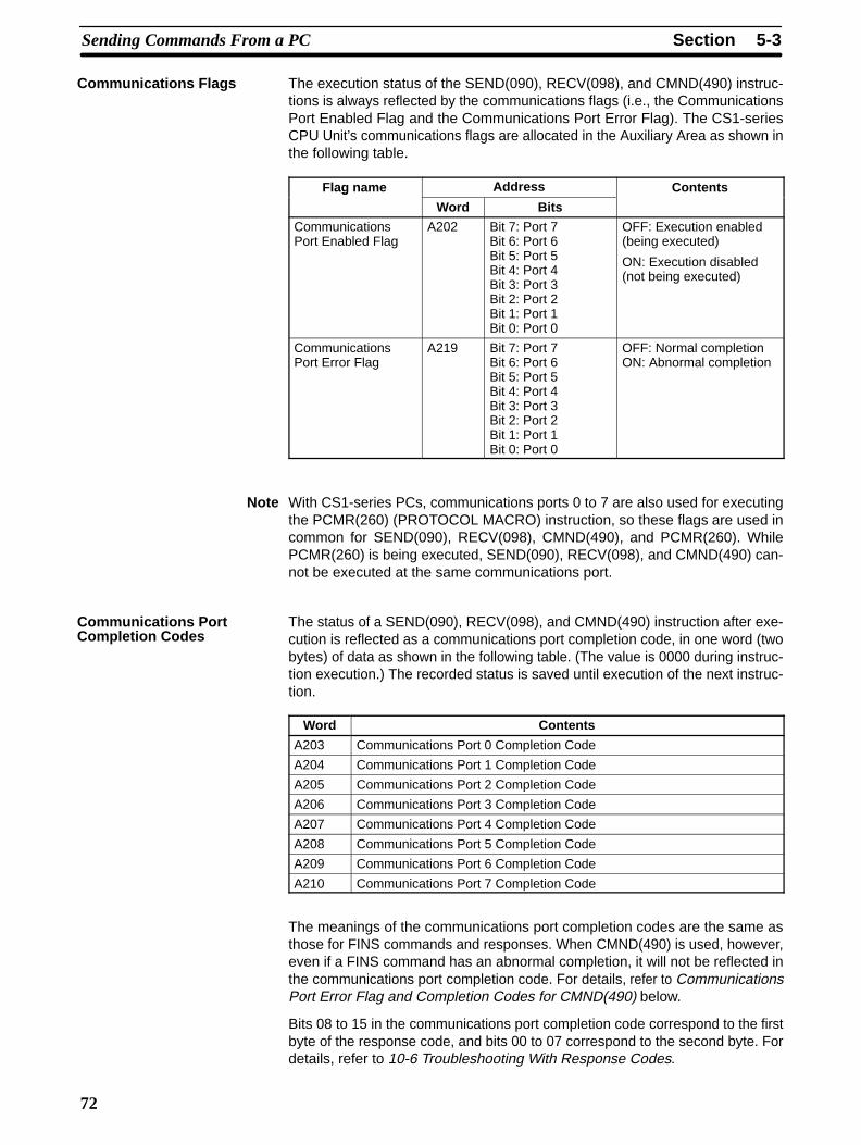
The execution status of the SEND(090), RECV(098), and CMND(490) instruc-tions is always reflected by the communications flags (i.e., the CommunicationsPort Enabled Flag and the Communications Port Error Flag). The CS1-seriesCPU Unit’s communications flags are allocated in the Auxiliary Area as shown inthe following table.
Flag name Address Contentsg
Word Bits
CommunicationsPort Enabled Flag
A202 Bit 7: Port 7Bit 6: Port 6Bit 5: Port 5Bit 4: Port 4Bit 3: Port 3Bit 2: Port 2Bit 1: Port 1Bit 0: Port 0
OFF: Execution enabled(being executed)
ON: Execution disabled(not being executed)
CommunicationsPort Error Flag
A219 Bit 7: Port 7Bit 6: Port 6Bit 5: Port 5Bit 4: Port 4Bit 3: Port 3Bit 2: Port 2Bit 1: Port 1Bit 0: Port 0
OFF: Normal completionON: Abnormal completion
Note With CS1-series PCs, communications ports 0 to 7 are also used for executingthe PCMR(260) (PROTOCOL MACRO) instruction, so these flags are used incommon for SEND(090), RECV(098), CMND(490), and PCMR(260). WhilePCMR(260) is being executed, SEND(090), RECV(098), and CMND(490) can-not be executed at the same communications port.
The status of a SEND(090), RECV(098), and CMND(490) instruction after exe-cution is reflected as a communications port completion code, in one word (twobytes) of data as shown in the following table. (The value is 0000 during instruc-tion execution.) The recorded status is saved until execution of the next instruc-tion.
Word Contents
A203 Communications Port 0 Completion Code
A204 Communications Port 1 Completion Code
A205 Communications Port 2 Completion Code
A206 Communications Port 3 Completion Code
A207 Communications Port 4 Completion Code
A208 Communications Port 5 Completion Code
A209 Communications Port 6 Completion Code
A210 Communications Port 7 Completion Code
The meanings of the communications port completion codes are the same asthose for FINS commands and responses. When CMND(490) is used, however,even if a FINS command has an abnormal completion, it will not be reflected inthe communications port completion code. For details, refer to CommunicationsPort Error Flag and Completion Codes for CMND(490) below.
Bits 08 to 15 in the communications port completion code correspond to the firstbyte of the response code, and bits 00 to 07 correspond to the second byte. Fordetails, refer to 10-6 Troubleshooting With Response Codes.
Communications Flags
Communications PortCompletion Codes
5-3SectionSending Commands From a PC
73
Communications Port Error Flag and Completion Codes CMND(490)
Errors that occur when CMND(490) is used generate a Communications PortError Flag and are recorded in a communications port completion code only inthe following cases:
• When a response timeout error has occurred.
• When the number of communications data bytes exceeds the maximum valuefor the Unit (i.e., 2,000 bytes for the Ethernet Unit).
• When the actual number of response bytes is greater than the number of re-ception bytes that has been set. (The response is not stored in this case.)
Errors other than these are recorded in the response codes of the responsesstored from the beginning response storage word onwards. Be careful of these,because there are no Communications Port Error Flags and they are not re-corded in a communications port completion code.
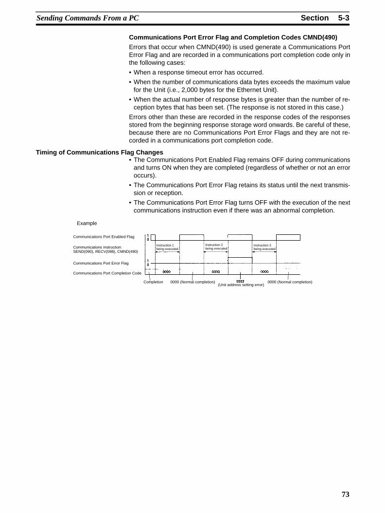
Timing of Communications Flag Changes• The Communications Port Enabled Flag remains OFF during communications
and turns ON when they are completed (regardless of whether or not an erroroccurs).
• The Communications Port Error Flag retains its status until the next transmis-sion or reception.
• The Communications Port Error Flag turns OFF with the execution of the nextcommunications instruction even if there was an abnormal completion.
Example
Communications Port Enabled Flag
Communications instruction:SEND(090), RECV(098), CMND(490)
Communications Port Error Flag
Communications Port Completion Code
Instruction 1 being executed.
Instruction 2 being executed.
Instruction 3 being executed.
0000 (Normal completion)0000 (Normal completion)(Unit address setting error)
Completion
5-3SectionSending Commands From a PC
74
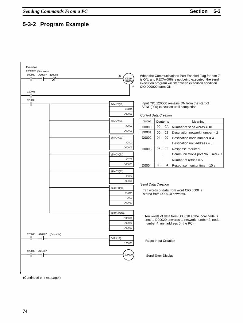
5-3-2 Program Example
When the Communications Port Enabled Flag for port 7is ON, and RECV(098) is not being executed, the sendexecution program will start when execution conditionCIO 000000 turns ON.
Input CIO 120000 remains ON from the start of SEND(090) execution until completion.
Control Data Creation
Contents Meaning
Number of send words = 10
Destination network number = 2
Destination node number = 4
Destination unit address = 0
Response required.
Communications port No. used = 7
Number of retries = 5
Response monitor time = 10 s
Send Data Creation
Ten words of data from word CIO 0000 isstored from D00010 onwards.
Ten words of data from D00010 at the local node issent to D00020 onwards at network number 2, nodenumber 4, unit address 0 (the PC).
Reset Input Creation
Send Error Display
KEEP120000
000000 A20207 120002
120001
@MOV(21)
#000A
D00000
120000
@MOV(21)
#0002
D00001
@MOV(21)
#0400
D00002
@MOV(21)
#0705
D00003
@MOV(21)
#0064
D00004
@XFER(70)
#000A
0000
D00010
@SEND(90)
D00010
D00020
D00000
DIFU(13)
120001
120000 A20207
120000
120000 A21907
Execution
condition (See note)
(Continued on next page.)
S
R
(See note)
00 0A
00 02
04 00
07 05
00 64
D0000
D0001
D0002
D0003
D0004
Word
5-3SectionSending Commands From a PC
75
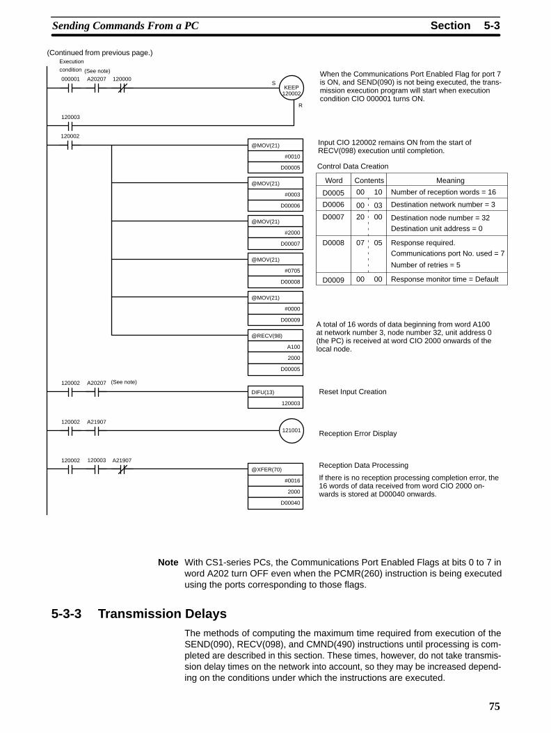
When the Communications Port Enabled Flag for port 7is ON, and SEND(090) is not being executed, the trans-mission execution program will start when executioncondition CIO 000001 turns ON.
Input CIO 120002 remains ON from the start ofRECV(098) execution until completion.
Control Data Creation
Word
Number of reception words = 16
Destination network number = 3
Destination node number = 32
Destination unit address = 0
Response required.Communications port No. used = 7
Number of retries = 5
Response monitor time = Default
A total of 16 words of data beginning from word A100at network number 3, node number 32, unit address 0(the PC) is received at word CIO 2000 onwards of thelocal node.
Reset Input Creation
Reception Error Display
Reception Data Processing
If there is no reception processing completion error, the16 words of data received from word CIO 2000 on-wards is stored at D00040 onwards.
KEEP120002
000001 A20207 120000
120003
@MOV(21)
#0010
D00005
@MOV(21)
#0003
D00006
@MOV(21)
#2000
D00007
@MOV(21)
#0705
D00008
@MOV(21)
#0000
D00009
@RECV(98)
A100
2000
D00005
DIFU(13)
120003
120002 A20207
121001
120002 A21907
Execution
condition (See note)
(Continued from previous page.)
120002
@XFER(70)
#0016
2000
D00040
120002 120003 A21907
(See note)
S
R
Contents Meaning
00 10
00 03
20 00
07 05
00 00
D0005
D0006
D0007
D0008
D0009
Note With CS1-series PCs, the Communications Port Enabled Flags at bits 0 to 7 inword A202 turn OFF even when the PCMR(260) instruction is being executedusing the ports corresponding to those flags.
5-3-3 Transmission DelaysThe methods of computing the maximum time required from execution of theSEND(090), RECV(098), and CMND(490) instructions until processing is com-pleted are described in this section. These times, however, do not take transmis-sion delay times on the network into account, so they may be increased depend-ing on the conditions under which the instructions are executed.
5-3SectionSending Commands From a PC
76
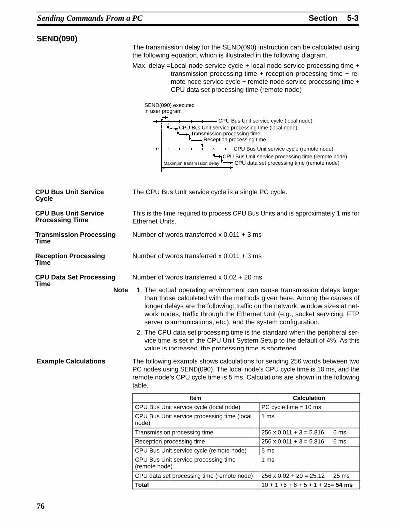
SEND(090)The transmission delay for the SEND(090) instruction can be calculated usingthe following equation, which is illustrated in the following diagram.
Max. delay =Local node service cycle + local node service processing time +transmission processing time + reception processing time + re-mote node service cycle + remote node service processing time +CPU data set processing time (remote node)
Maximum transmission delay
SEND(090) executedin user program
CPU Bus Unit service cycle (local node)CPU Bus Unit service processing time (local node)
Transmission processing timeReception processing time
CPU Bus Unit service cycle (remote node)CPU Bus Unit service processing time (remote node)
CPU data set processing time (remote node)
The CPU Bus Unit service cycle is a single PC cycle.
This is the time required to process CPU Bus Units and is approximately 1 ms forEthernet Units.
Number of words transferred x 0.011 + 3 ms
Number of words transferred x 0.011 + 3 ms
Number of words transferred x 0.02 + 20 ms
Note 1. The actual operating environment can cause transmission delays largerthan those calculated with the methods given here. Among the causes oflonger delays are the following: traffic on the network, window sizes at net-work nodes, traffic through the Ethernet Unit (e.g., socket servicing, FTPserver communications, etc.), and the system configuration.
2. The CPU data set processing time is the standard when the peripheral ser-vice time is set in the CPU Unit System Setup to the default of 4%. As thisvalue is increased, the processing time is shortened.
Example Calculations The following example shows calculations for sending 256 words between twoPC nodes using SEND(090). The local node’s CPU cycle time is 10 ms, and theremote node’s CPU cycle time is 5 ms. Calculations are shown in the followingtable.
Item Calculation
CPU Bus Unit service cycle (local node) PC cycle time = 10 ms
CPU Bus Unit service processing time (localnode)
1 ms
Transmission processing time 256 x 0.011 + 3 = 5.816 6 ms
Reception processing time 256 x 0.011 + 3 = 5.816 6 ms
CPU Bus Unit service cycle (remote node) 5 ms
CPU Bus Unit service processing time(remote node)
1 ms
CPU data set processing time (remote node) 256 x 0.02 + 20 = 25.12 25 ms
Total 10 + 1 +6 + 6 + 5 + 1 + 25= 54 ms
CPU Bus Unit ServiceCycle
CPU Bus Unit ServiceProcessing Time
Transmission ProcessingTime
Reception ProcessingTime
CPU Data Set ProcessingTime
5-3SectionSending Commands From a PC
77
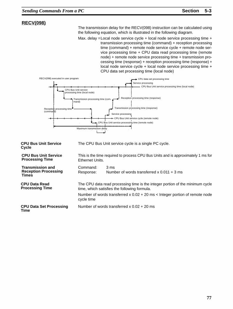
RECV(098)The transmission delay for the RECV(098) instruction can be calculated usingthe following equation, which is illustrated in the following diagram.
Max. delay =Local node service cycle + local node service processing time +transmission processing time (command) + reception processingtime (command) + remote node service cycle + remote node ser-vice processing time + CPU data read processing time (remotenode) + remote node service processing time + transmission pro-cessing time (response) + reception processing time (response) +local node service cycle + local node service processing time +CPU data set processing time (local node)
Maximum transmission delay
RECV(098) executed in user program
CPU Bus Unit service processing time (local node)
Transmission processing time (com-mand)
Reception processing time(command)
CPU Bus Unit service cycle (remote node)
CPU Bus Unit service processing time (remote node)
CPU Bus Unit service processing time (local node)
Reception processing time (response)
Transmission processing time (response)
CPU data set processing time
Service processing
Service processing
The CPU Bus Unit service cycle is a single PC cycle.
This is the time required to process CPU Bus Units and is approximately 1 ms forEthernet Units.
Command: 3 msResponse: Number of words transferred x 0.011 + 3 ms
The CPU data read processing time is the integer portion of the minimum cycletime, which satisfies the following formula.
Number of words transferred x 0.02 + 20 ms < Integer portion of remote nodecycle time
Number of words transferred x 0.02 + 20 ms
CPU Bus Unit ServiceCycle
CPU Bus Unit ServiceProcessing Time
Transmission andReception ProcessingTimes
CPU Data ReadProcessing Time
CPU Data Set ProcessingTime
5-4SectionSending Commands From a Host Computer
78
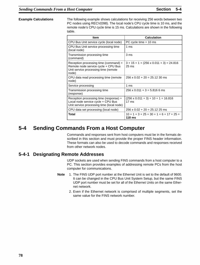
Example Calculations The following example shows calculations for receiving 256 words between twoPC nodes using RECV(098). The local node’s CPU cycle time is 10 ms, and theremote node’s CPU cycle time is 15 ms. Calculations are shown in the followingtable.
Item Calculation
CPU Bus Unit service cycle (local node) PC cycle time = 10 ms
CPU Bus Unit service processing time(local node)
1 ms
Transmission processing time(command)
3 ms
Reception processing time (command) +Remote node service cycle + CPU BusUnit service processing time (remotenode)
3 + 15 + 1 + (256 x 0.011 + 3) = 24.81625 ms
CPU data read processing time (remotenode)
256 x 0.02 + 20 = 25.12 30 ms
Service processing 1 ms
Transmission processing time(response)
256 x 0.011 + 3 = 5.816 6 ms
Reception processing time (response) +Local node service cycle + CPU BusUnit service processing time (local node)
(256 x 0.011 + 3) + 10 + 1 = 16.81617 ms
CPU data set processing (local node) 256 x 0.02 + 20 = 25.12 25 ms
Total 10 + 1 + 3 + 25 + 30 + 1 + 6 + 17 + 25 =118 ms
5-4 Sending Commands From a Host ComputerCommands and responses sent from host computers must be in the formats de-scribed in this section and must provide the proper FINS header information.These formats can also be used to decode commands and responses receivedfrom other network nodes.
5-4-1 Designating Remote AddressesUDP sockets are used when sending FINS commands from a host computer to aPC. This section provides examples of addressing remote PCs from the hostcomputer for communications.
Note 1. The FINS UDP port number at the Ethernet Unit is set to the default of 9600.It can be changed in the CPU Bus Unit System Setup, but the same FINSUDP port number must be set for all of the Ethernet Units on the same Ether-net network.
2. Even if the Ethernet network is comprised of multiple segments, set thesame value for the FINS network number.
5-4SectionSending Commands From a Host Computer
79
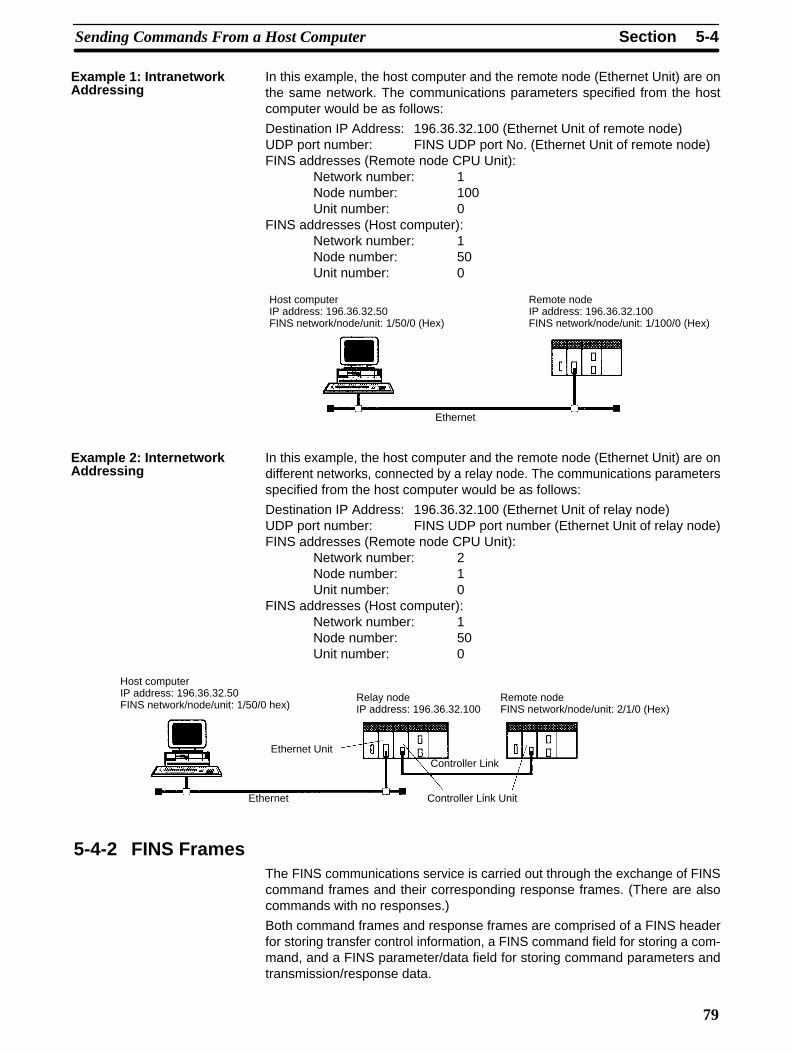
In this example, the host computer and the remote node (Ethernet Unit) are onthe same network. The communications parameters specified from the hostcomputer would be as follows:
Destination IP Address: 196.36.32.100 (Ethernet Unit of remote node)UDP port number: FINS UDP port No. (Ethernet Unit of remote node)FINS addresses (Remote node CPU Unit):
Network number: 1Node number: 100Unit number: 0
FINS addresses (Host computer):Network number: 1Node number: 50Unit number: 0
Host computerIP address: 196.36.32.50FINS network/node/unit: 1/50/0 (Hex)
Remote nodeIP address: 196.36.32.100FINS network/node/unit: 1/100/0 (Hex)
Ethernet
In this example, the host computer and the remote node (Ethernet Unit) are ondifferent networks, connected by a relay node. The communications parametersspecified from the host computer would be as follows:
Destination IP Address: 196.36.32.100 (Ethernet Unit of relay node)UDP port number: FINS UDP port number (Ethernet Unit of relay node)FINS addresses (Remote node CPU Unit):
Network number: 2Node number: 1Unit number: 0
FINS addresses (Host computer):Network number: 1Node number: 50Unit number: 0
Host computerIP address: 196.36.32.50FINS network/node/unit: 1/50/0 hex)
Relay nodeIP address: 196.36.32.100
Remote node FINS network/node/unit: 2/1/0 (Hex)
Ethernet UnitController Link
Ethernet Controller Link Unit
5-4-2 FINS FramesThe FINS communications service is carried out through the exchange of FINScommand frames and their corresponding response frames. (There are alsocommands with no responses.)
Both command frames and response frames are comprised of a FINS headerfor storing transfer control information, a FINS command field for storing a com-mand, and a FINS parameter/data field for storing command parameters andtransmission/response data.
Example 1: IntranetworkAddressing
Example 2: InternetworkAddressing
5-4SectionSending Commands From a Host Computer
80
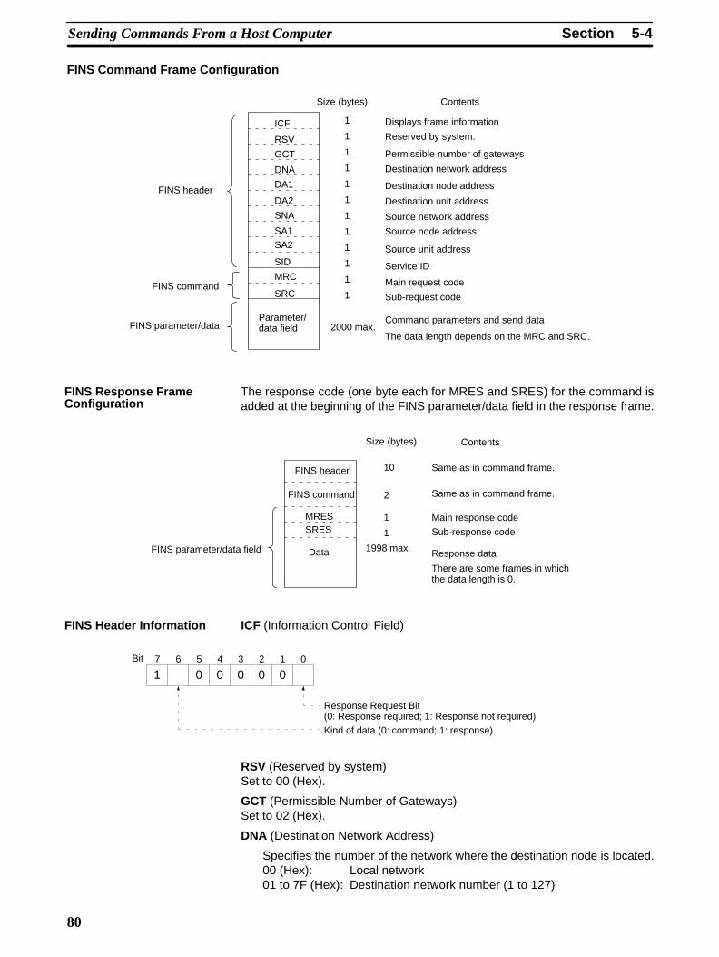
FINS Command Frame Configuration
FINS header
FINS command
FINS parameter/dataParameter/data field
Size (bytes) Contents
Displays frame information
Reserved by system.
Permissible number of gateways
Destination network address
Destination node address
Destination unit address
Source network address
Source node address
Source unit address
Service ID
Main request code
Sub-request code
2000 max.Command parameters and send data
The data length depends on the MRC and SRC.
1
1
1
1
1
1
1
1
1
1
1
1
ICF
RSV
GCT
DNA
DA1
DA2
SNA
SA1
SA2
SID
MRC
SRC
The response code (one byte each for MRES and SRES) for the command isadded at the beginning of the FINS parameter/data field in the response frame.
FINS parameter/data field
FINS header
FINS command
Data
Size (bytes) Contents
Same as in command frame.
Same as in command frame.
Main response code
Sub-response code
1998 max. Response data
There are some frames in whichthe data length is 0.
10
2
1
1
MRESSRES
ICF (Information Control Field)
7 6 5 4 3 2 1 0
1 0 0 0 0 0Bit
Response Request Bit (0: Response required; 1: Response not required)
Kind of data (0: command; 1: response)
RSV (Reserved by system)Set to 00 (Hex).
GCT (Permissible Number of Gateways)Set to 02 (Hex).
DNA (Destination Network Address)
Specifies the number of the network where the destination node is located.00 (Hex): Local network01 to 7F (Hex): Destination network number (1 to 127)
FINS Response FrameConfiguration
FINS Header Information
5-4SectionSending Commands From a Host Computer
81
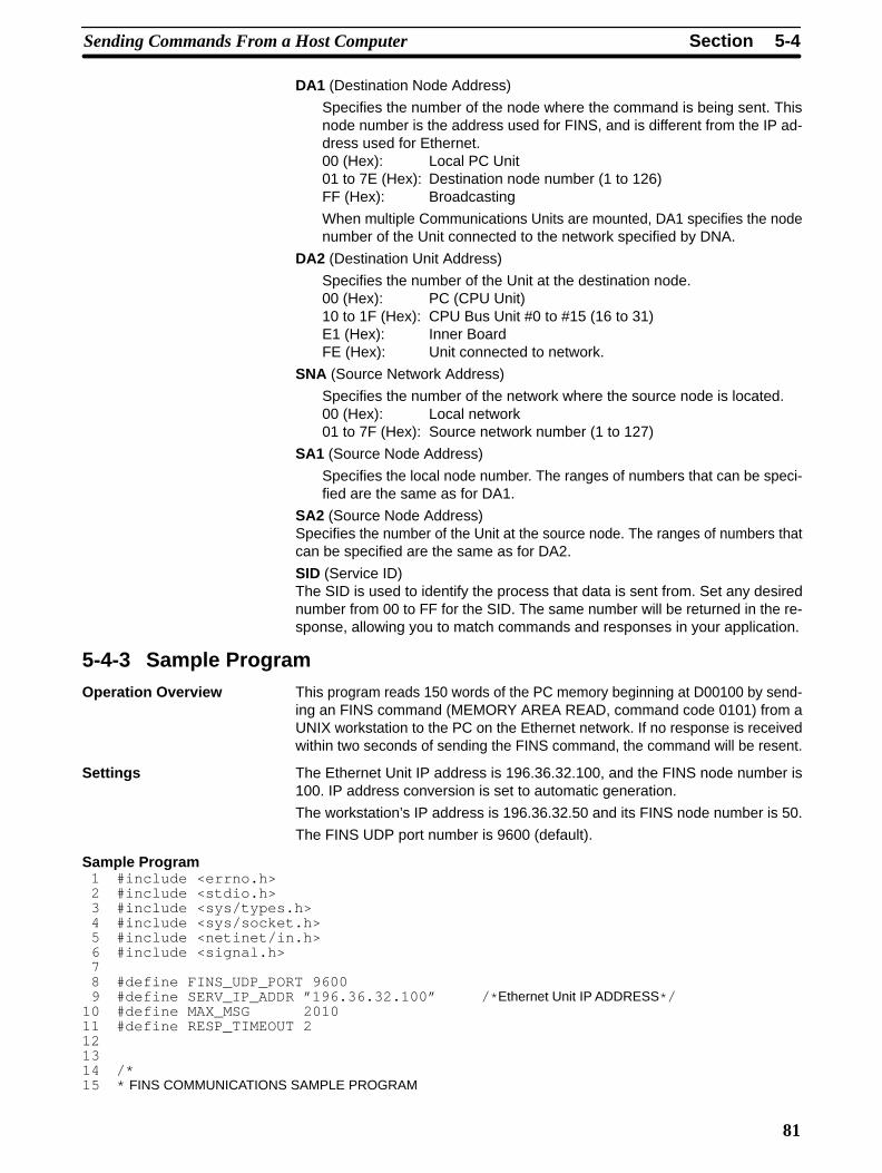
DA1 (Destination Node Address)
Specifies the number of the node where the command is being sent. Thisnode number is the address used for FINS, and is different from the IP ad-dress used for Ethernet.00 (Hex): Local PC Unit01 to 7E (Hex): Destination node number (1 to 126)FF (Hex): Broadcasting
When multiple Communications Units are mounted, DA1 specifies the nodenumber of the Unit connected to the network specified by DNA.
DA2 (Destination Unit Address)
Specifies the number of the Unit at the destination node.00 (Hex): PC (CPU Unit)10 to 1F (Hex): CPU Bus Unit #0 to #15 (16 to 31)E1 (Hex): Inner BoardFE (Hex): Unit connected to network.
SNA (Source Network Address)
Specifies the number of the network where the source node is located.00 (Hex): Local network01 to 7F (Hex): Source network number (1 to 127)
SA1 (Source Node Address)
Specifies the local node number. The ranges of numbers that can be speci-fied are the same as for DA1.
SA2 (Source Node Address)Specifies the number of the Unit at the source node. The ranges of numbers thatcan be specified are the same as for DA2.
SID (Service ID)The SID is used to identify the process that data is sent from. Set any desirednumber from 00 to FF for the SID. The same number will be returned in the re-sponse, allowing you to match commands and responses in your application.
5-4-3 Sample ProgramOperation Overview This program reads 150 words of the PC memory beginning at D00100 by send-
ing an FINS command (MEMORY AREA READ, command code 0101) from aUNIX workstation to the PC on the Ethernet network. If no response is receivedwithin two seconds of sending the FINS command, the command will be resent.
Settings The Ethernet Unit IP address is 196.36.32.100, and the FINS node number is100. IP address conversion is set to automatic generation.
The workstation’s IP address is 196.36.32.50 and its FINS node number is 50.
The FINS UDP port number is 9600 (default).
Sample Program 1 #include <errno.h> 2 #include <stdio.h> 3 #include <sys/types.h> 4 #include <sys/socket.h> 5 #include <netinet/in.h> 6 #include <signal.h> 7 8 #define FINS_UDP_PORT 9600 9 #define SERV_IP_ADDR ”196.36.32.100” / * Ethernet Unit IP ADDRESS* /10 #define MAX_MSG 201011 #define RESP_TIMEOUT 2121314 /*15 * FINS COMMUNICATIONS SAMPLE PROGRAM
5-4SectionSending Commands From a Host Computer
82
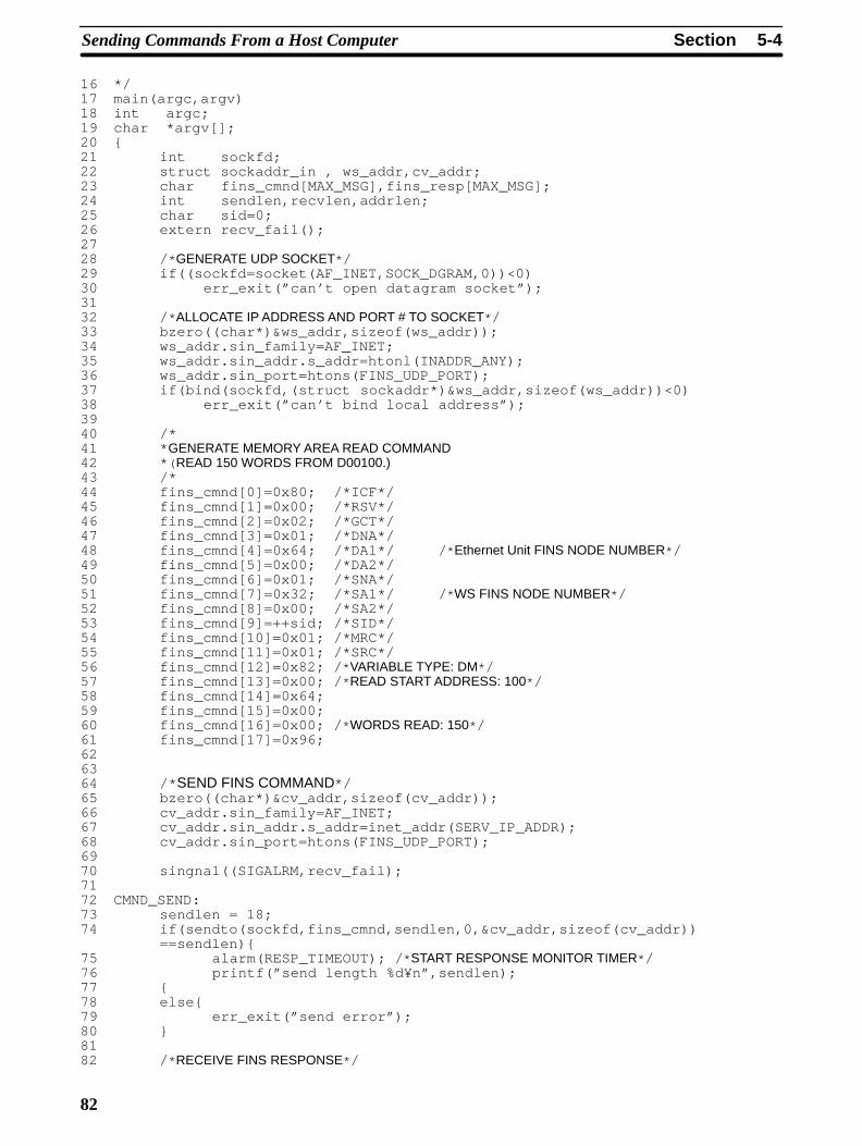
16 */17 main(argc,argv)18 int argc;19 char *argv[];20 {21 int sockfd;22 struct sockaddr_in , ws_addr,cv_addr;23 char fins_cmnd[MAX_MSG],fins_resp[MAX_MSG];24 int sendlen,recvlen,addrlen;25 char sid=0;26 extern recv_fail();2728 / * GENERATE UDP SOCKET* /29 if((sockfd=socket(AF_INET,SOCK_DGRAM,0))<0)30 err_exit(”can’t open datagram socket”);3132 / * ALLOCATE IP ADDRESS AND PORT # TO SOCKET* /33 bzero((char*)&ws_addr,sizeof(ws_addr));34 ws_addr.sin_family=AF_INET;35 ws_addr.sin_addr.s_addr=htonl(INADDR_ANY);36 ws_addr.sin_port=htons(FINS_UDP_PORT);37 if(bind(sockfd,(struct sockaddr*)&ws_addr,sizeof(ws_addr))<0)38 err_exit(”can’t bind local address”);3940 /*41 * GENERATE MEMORY AREA READ COMMAND42 * ( READ 150 WORDS FROM D00100.)43 /*44 fins_cmnd[0]=0x80; /*ICF*/45 fins_cmnd[1]=0x00; /*RSV*/46 fins_cmnd[2]=0x02; /*GCT*/47 fins_cmnd[3]=0x01; /*DNA*/48 fins_cmnd[4]=0x64; /*DA1*/ / * Ethernet Unit FINS NODE NUMBER* /49 fins_cmnd[5]=0x00; /*DA2*/50 fins_cmnd[6]=0x01; /*SNA*/51 fins_cmnd[7]=0x32; /*SA1*/ / * WS FINS NODE NUMBER* /52 fins_cmnd[8]=0x00; /*SA2*/53 fins_cmnd[9]=++sid; /*SID*/54 fins_cmnd[10]=0x01; /*MRC*/55 fins_cmnd[11]=0x01; /*SRC*/56 fins_cmnd[12]=0x82; / * VARIABLE TYPE: DM* /57 fins_cmnd[13]=0x00; / * READ START ADDRESS: 100* /58 fins_cmnd[14]=0x64;59 fins_cmnd[15]=0x00;60 fins_cmnd[16]=0x00; / * WORDS READ: 150* /61 fins_cmnd[17]=0x96;626364 /* SEND FINS COMMAND*/65 bzero((char*)&cv_addr,sizeof(cv_addr));66 cv_addr.sin_family=AF_INET;67 cv_addr.sin_addr.s_addr=inet_addr(SERV_IP_ADDR);68 cv_addr.sin_port=htons(FINS_UDP_PORT);6970 singnal((SIGALRM,recv_fail);7172 CMND_SEND:73 sendlen = 18;74 if(sendto(sockfd,fins_cmnd,sendlen,0,&cv_addr,sizeof(cv_addr))
==sendlen){75 alarm(RESP_TIMEOUT); / * START RESPONSE MONITOR TIMER* /76 printf(”send length %d¥n”,sendlen);77 {78 else{79 err_exit(”send error”);80 }8182 / * RECEIVE FINS RESPONSE* /
5-4SectionSending Commands From a Host Computer
83
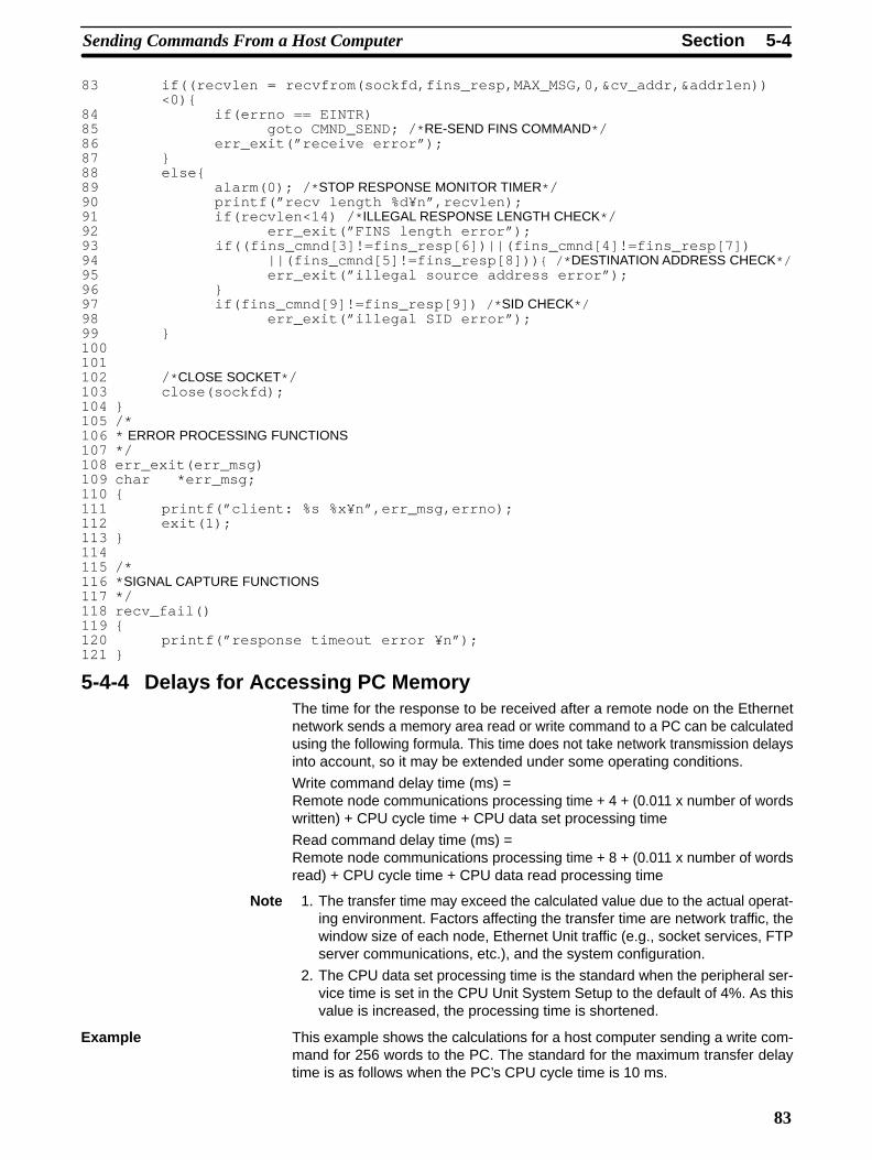
83 if((recvlen = recvfrom(sockfd,fins_resp,MAX_MSG,0,&cv_addr,&addrlen))<0){
84 if(errno == EINTR)85 goto CMND_SEND; / * RE-SEND FINS COMMAND* /86 err_exit(”receive error”);87 }88 else{89 alarm(0); / * STOP RESPONSE MONITOR TIMER* /90 printf(”recv length %d¥n”,recvlen);91 if(recvlen<14) / * ILLEGAL RESPONSE LENGTH CHECK* /92 err_exit(”FINS length error”);93 if((fins_cmnd[3]!=fins_resp[6])||(fins_cmnd[4]!=fins_resp[7])94 ||(fins_cmnd[5]!=fins_resp[8])) { /* DESTINATION ADDRESS CHECK*/95 err_exit(”illegal source address error”);96 }97 if(fins_cmnd[9]!=fins_resp[9]) /* SID CHECK*/98 err_exit(”illegal SID error”);99 }100101102 / * CLOSE SOCKET* /103 close(sockfd);104 }105 /*106 * ERROR PROCESSING FUNCTIONS107 */108 err_exit(err_msg)109 char *err_msg;110 {111 printf(”client: %s %x¥n”,err_msg,errno);112 exit(1);113 }114115 /*116 * SIGNAL CAPTURE FUNCTIONS117 */118 recv_fail()119 {120 printf(”response timeout error ¥n”);121 }
5-4-4 Delays for Accessing PC MemoryThe time for the response to be received after a remote node on the Ethernetnetwork sends a memory area read or write command to a PC can be calculatedusing the following formula. This time does not take network transmission delaysinto account, so it may be extended under some operating conditions.
Write command delay time (ms) =Remote node communications processing time + 4 + (0.011 x number of wordswritten) + CPU cycle time + CPU data set processing time
Read command delay time (ms) = Remote node communications processing time + 8 + (0.011 x number of wordsread) + CPU cycle time + CPU data read processing time
Note 1. The transfer time may exceed the calculated value due to the actual operat-ing environment. Factors affecting the transfer time are network traffic, thewindow size of each node, Ethernet Unit traffic (e.g., socket services, FTPserver communications, etc.), and the system configuration.
2. The CPU data set processing time is the standard when the peripheral ser-vice time is set in the CPU Unit System Setup to the default of 4%. As thisvalue is increased, the processing time is shortened.
This example shows the calculations for a host computer sending a write com-mand for 256 words to the PC. The standard for the maximum transfer delaytime is as follows when the PC’s CPU cycle time is 10 ms.
Example
5-5SectionFINS Server
84
Maximum transfer delay time= Host computer communications processing time + (0.011 x 256) + 10+ (256 x 0.02 + 20) = host computer communications processing time + 42 ms
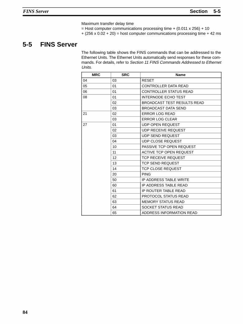
5-5 FINS ServerThe following table shows the FINS commands that can be addressed to theEthernet Units. The Ethernet Units automatically send responses for these com-mands. For details, refer to Section 11 FINS Commands Addressed to EthernetUnits.
MRC SRC Name
04 03 RESET
05 01 CONTROLLER DATA READ
06 01 CONTROLLER STATUS READ
08 01 INTERNODE ECHO TEST
02 BROADCAST TEST RESULTS READ
03 BROADCAST DATA SEND
21 02 ERROR LOG READ
03 ERROR LOG CLEAR
27 01 UDP OPEN REQUEST
02 UDP RECEIVE REQUEST
03 UDP SEND REQUEST
04 UDP CLOSE REQUEST
10 PASSIVE TCP OPEN REQUEST
11 ACTIVE TCP OPEN REQUEST
12 TCP RECEIVE REQUEST
13 TCP SEND REQUEST
14 TCP CLOSE REQUEST
20 PING
50 IP ADDRESS TABLE WRITE
60 IP ADDRESS TABLE READ
61 IP ROUTER TABLE READ
62 PROTOCOL STATUS READ
63 MEMORY STATUS READ
64 SOCKET STATUS READ
65 ADDRESS INFORMATION READ