section 6 - neopost technologies · section 6.3 - cpu circuit diagram page 6 - 6 issue 3 apr 2008....
TRANSCRIPT

Page 6 - 1
AS850 SERVICE MANUAL
SECTION 6
ElectricalandCircuit Diagrams
ISSUE 2A PR 2008

Page 6 - 2
AS850 SERVICE MANUAL
34
5
7
8 11
910
12 13
LOCATION OF SENSORS
2
6
1
ISSUE 4MAY 2008
Page 6 - 3
AS850 SERVICE MANUAL
ISSUE 4MAY 2008
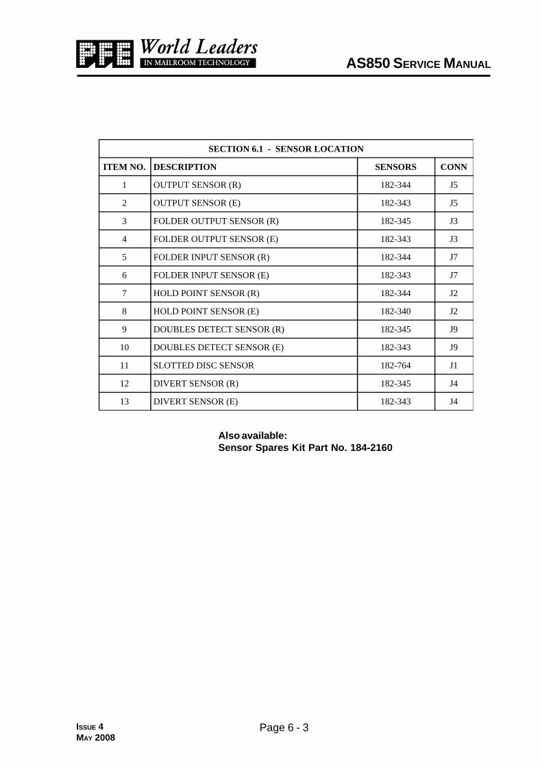
SECTION 6.1 - SENSOR LOCATION
ITEM NO. DESCRIPTION SENSORS CONN
1 OUTPUT SENSOR (R) 182-344 J5
2 OUTPUT SENSOR (E) 182-343 J5
3 FOLDER OUTPUT SENSOR (R) 182-345 J3
4 FOLDER OUTPUT SENSOR (E) 182-343 J3
5 FOLDER INPUT SENSOR (R) 182-344 J7
6 FOLDER INPUT SENSOR (E) 182-343 J7
7 HOLD POINT SENSOR (R) 182-344 J2
8 HOLD POINT SENSOR (E) 182-340 J2
9 DOUBLES DETECT SENSOR (R) 182-345 J9
10 DOUBLES DETECT SENSOR (E) 182-343 J9
11 SLOTTED DISC SENSOR 182-764 J1
12 DIVERT SENSOR (R) 182-345 J4
13 DIVERT SENSOR (E) 182-343 J4
Also available:Sensor Spares Kit Part No. 184-2160

Page 6 - 4
AS850 SERVICE MANUAL
1
7,8
65
9
3 4
LOCATION OF COMPONENTS
10,11
12
13
ISSUE 4APR 2008
14
16
15

Page 6 - 5
AS850 SERVICE MANUAL
ISSUE 5JUL 2009
STNENOPMOCFONOITACOL-2.6NOITCES
METI.ON
NOITPIRCSED .ONTRAP YTITNAUQ
1 SENIHCAMV042ROF)V591(36MPROTOM 050-971 1
3 BCPUPC 008-081 1
4 )V032(BCPUSP/LORTNOCDEEPS 166-081 1
5 BCPLENAPLORTNOC 731-081 1
6 V42,L4CDB,DIONELOS 421-181 1
7 TEKCOSTUPNISNIAM 813-861 1
8 )V032(mm02A51.3,ESUF 301-531 1
9 EKOHC 102-931 1
01 TCATNOCC/NHCTIWSPOTS 0338-131 2
11 HCTIWSPOTS.ME,NOTTUBROTAUTCA 0438-131 1
21 )V032(RETLIFSNIAM 221-931 1
31 HCTIWSDEERREVOCPOT 714-281 1
41 TEKCOSTUPTUOSNIAM 523-861 1
51 BCPHCTIWSROTOMCA 466-081 1
61 TEKCOSLANGISREKCATS 545-861 1
Sec
tio
n 6
.3 -
CP
U C
ircu
it D
iag
ram
Page 6 - 6 ISSUE 3APR 2008
Page 6 - 7
AS850 SERVICE MANUAL
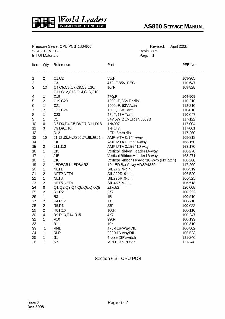
Pressure Sealer CPU PCB 180-800 Revised: April 2008SEALER_M.CCT Revision: 5Bill Of Materials Page 1
Item Qty Reference Part PFE No.__________________________________________________________________________________________________
1 2 C1,C2 33pF 109-9032 1 C3 470uF 35V, FEC 110-6473 13 C4,C5,C6,C7,C8,C9,C10, 10nF 109-925
C11,C12,C13,C14,C15,C164 1 C18 470pF 109-9085 2 C19,C20 1000uF, 35V Radial 110-2106 1 C21 1000uF, 63V Axial 112-2107 2 C22,C24 10uF, 35V Tant 110-0108 1 C23 47uF, 16V Tant 110-0479 1 D1 24V 5W, ZENER 1N5359B 117-12210 8 D2,D3,D4,D5,D6,D7,D11,D13 1N4007 117-00411 3 D8,D9,D10 1N4148 117-00112 1 D12 LED, 5mm dia 117-26013 10 J1,J2,J3,J4,J5,J6,J7,J8,J9,J14 AMP MTA 0.1" 4-way 168-91314 1 J10 AMP MTA 0.156" 4-way 168-15015 2 J11,J12 AMP MTA 0.156" 10-way 168-17016 1 J13 Vertical Ribbon Header 14-way 168-27017 1 J15 Vertical Ribbon Header 16-way 168-27118 1 J16 Vertical Ribbon Header 10-Way (No latch) 168-26819 2 LEDBAR1,LEDBAR2 10-LED Bar Array HDSP4820 117-26920 1 NET1 SIL 2K2, 9-pin 106-51921 2 NET2,NET4 SIL 330R, 9-pin 106-52022 1 NET3 SIL 220R, 9-pin 106-52523 2 NET5,NET6 SIL 4K7, 9-pin 106-51824 8 Q1,Q2,Q3,Q4,Q5,Q6,Q7,Q8 ZTX653 120-00525 2 R1,R2 2K2 100-22226 1 R3 1R 100-91027 2 R4,R12 1K 100-21028 2 R5,R6 33R 100-03329 2 R8,R16 100R 100-11030 4 R9,R13,R14,R15 4K7 100-24731 1 R10 330R 100-13332 1 R11 10K 100-31033 1 RN1 470R 16-Way DIL 106-50234 1 RN2 220R 16-way DIL 106-52335 1 S1 4-pole DIP switch 131-24636 1 S2 Mini Push Button 131-248
Section 6.3 - CPU PCB
ISSUE 3APR 2008
Page 6 - 8
AS850 SERVICE MANUAL
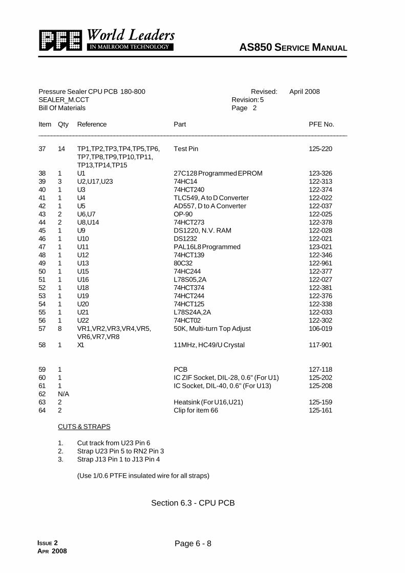
Pressure Sealer CPU PCB 180-800 Revised: April 2008SEALER_M.CCT Revision: 5Bill Of Materials Page 2
Item Qty Reference Part PFE No.__________________________________________________________________________________________________
37 14 TP1,TP2,TP3,TP4,TP5,TP6, Test Pin 125-220TP7,TP8,TP9,TP10,TP11,TP13,TP14,TP15
38 1 U1 27C128 Programmed EPROM 123-32639 3 U2,U17,U23 74HC14 122-31340 1 U3 74HCT240 122-37441 1 U4 TLC549, A to D Converter 122-02242 1 U5 AD557, D to A Converter 122-03743 2 U6,U7 OP-90 122-02544 2 U8,U14 74HCT273 122-37845 1 U9 DS1220, N.V. RAM 122-02846 1 U10 DS1232 122-02147 1 U11 PAL16L8 Programmed 123-02148 1 U12 74HCT139 122-34649 1 U13 80C32 122-96150 1 U15 74HC244 122-37751 1 U16 L78S05,2A 122-02752 1 U18 74HCT374 122-38153 1 U19 74HCT244 122-37654 1 U20 74HCT125 122-33855 1 U21 L78S24A,2A 122-03356 1 U22 74HCT02 122-30257 8 VR1,VR2,VR3,VR4,VR5, 50K, Multi-turn Top Adjust 106-019
VR6,VR7,VR858 1 X1 11MHz, HC49/U Crystal 117-901
59 1 PCB 127-11860 1 IC ZIF Socket, DIL-28, 0.6" (For U1) 125-20261 1 IC Socket, DIL-40, 0.6" (For U13) 125-20862 N/A63 2 Heatsink (For U16,U21) 125-15964 2 Clip for item 66 125-161
CUTS & STRAPS
1. Cut track from U23 Pin 62. Strap U23 Pin 5 to RN2 Pin 33. Strap J13 Pin 1 to J13 Pin 4
(Use 1/0.6 PTFE insulated wire for all straps)
Section 6.3 - CPU PCB
ISSUE 2APR 2008

Page 6 - 9ISSUE 2APR 2008

Page 6 - 10
AS850 SERVICE MANUAL
ISSUE 2APR 2008
Pressure Sealer Speed control/PSU Revised: April 2008180-661 (230V) Revision: 2Bill Of Materials April 2008 Page 1Item Qty Reference Part PFE Part No.______________________________________________________________________________________________________________
1 1 BR1 4A 800V, GBU4K 117-3122 1 BR2 1A 200V, W002 117-3013 1 C1 22uF, 35V Radial Electrolytic 110-7224 2 C2,C4 47uF, 35V Radial Electrolytic 110-5475 1 C3 470uF, 35V Radial Electrolytic 110-6476 3 C5,C13,C18 4.7uF, 50V Radial Electrolytic 111-9477 1 C6 1uF, 50V Radial Electrolytic 111-7108 1 C7 4700uF 40V 111-2479 N/A10 3 C9,C16,C17 0.47uF 250V, 'X' Type 108-44611 3 C14,C15,C19 220uF, 25V 110-12212 1 C21 0.47uF, 63V 109-44713 1 C22 4700uF 25V 110-24714 2 C23,C24 0.22uF, 100V 109-42215 1 L1 4A .2mH, ROXBURGH SMV40 139-20716 N/A17 N/A18 3 D1,D2,D18 6A, P600K 117-01619 15 D4,D5,D7,D8,D9,D10,D11 1N4007 117-004
D12,D13,D14,D15,D16,D17,D19,D21
20 2 D6,D20 1N4148 117-00121 1 J1 AMP MTA 0.1" 4-way 168-91322 1 J2 Vertical Ribbon Header 14-Way 168-27023 1 J3 AMP MTA 0.156" - 5-way 168-16024 1 J4 AMP MTA 0.156" - 6-way 168-19025 1 J5 AMP MTA 0.156" - 4-way 168-15026 2 JP1,JP2 Link with 22SWG insulated TCW 120v only (not on 240v)27 2 LINK1,LINK2 Link with 22SWG insulated TCW for 240v or 120v28 1 K1 Relay, 240V 10A 130-01529 2 K2,K3 Relay, SHRACK RP420-012 130-03030 1 LED1 LED, 5mm dia, RED 117-26031 4 Q1,Q2,Q3,Q4 ZTX653 120-00532 6 R1,R2,R7,R24,R35,R41 1KW 100-21033 1 R3 270W 100-12734 1 R4 1W, 7W 104-91035 3 R5,R20,R43 2K2 100-22236 2 R6,R37 3K6 100-23637 1 R8 470K 100-44738 1 R9 1K5 100-21539 6 R10,R17,R25,R30,R32,R33 22K 100-322
Section 6.4 - Speed Control/PSU PCB

Page 6 - 11
AS850 SERVICE MANUAL
ISSUE 2APR 2008
Pressure Sealer Speed control/PSU Revised: April 2008180-661 (230V) Revision: 2Bill Of Materials April 2008 Page 1Item Qty Reference Part PFE Part No.______________________________________________________________________________________________________________
40 3 R11,R18,R34 10K 100-31041 1 R12 390W 100-13942 2 R13,R15 3K3 100-23343 1 R36 100W 100-11044 1 R19 4K7 100-24745 2 R21,R22 470W 100-14746 1 R23 47K 100-34747 2 R26,38 180K 100-41848 1 R27 12K 100-31249 1 R28 18K 100-31850 1 R29 120W 100-11251 1 R31 27K 100-32752 2 R39,R42 150W, 11W 105-11553 1 R40 R015, 4W 103-71554 2 RT1,RT2 60mA Trip, YM120D60N151 106-90355 2 RT3,RT4 200mA Trip, YM120D200N200 106-90456 2 RV1,RV2 Varistor, 275V 106-92557 2 SCR1,SCR2 BT151-800R 120-20158 1 T1 12-0-12 6VA 139-03259 1 T2 12-0 0-12 60VA 139-02760 2 U1,U3 TLP521-4A 122-01061 1 U2 TL074 122-03462 1 U4 LM324 122-03563 1 VR1 Pot, 2K, Multi-turn Top Adjust 106-03164 1 VR3 Pot, 10K, Multi-turn Top Adjust 106-02765 1 VR6 Pot, 20K, Multi-turn Top Adjust 106-02666 3 Z1,Z2,Z3 BZV85C10 117-117
67 1 PCB 127-12568 2 Heatsink (For SCR1,SCR2) 125-15969 2 Clips for above 125-16170 12 Ceramic beads 125-18671 0.8mt Sleeving 7mm 0.5 Wall 167-10772 1 Cable Tie 2.6 x 100mm 169-10273 1 Clip Sticky 10mm 169-111
Section 6.4 - Speed Control/PSU PCB
Page 6 - 12
Sec
tio
n 6
.5 -
Co
ntr
ol P
anel
Cir
cuit
Dia
gra
m
ISSUE 2APR 2008
Page 6 - 13
AS850 SERVICE MANUAL
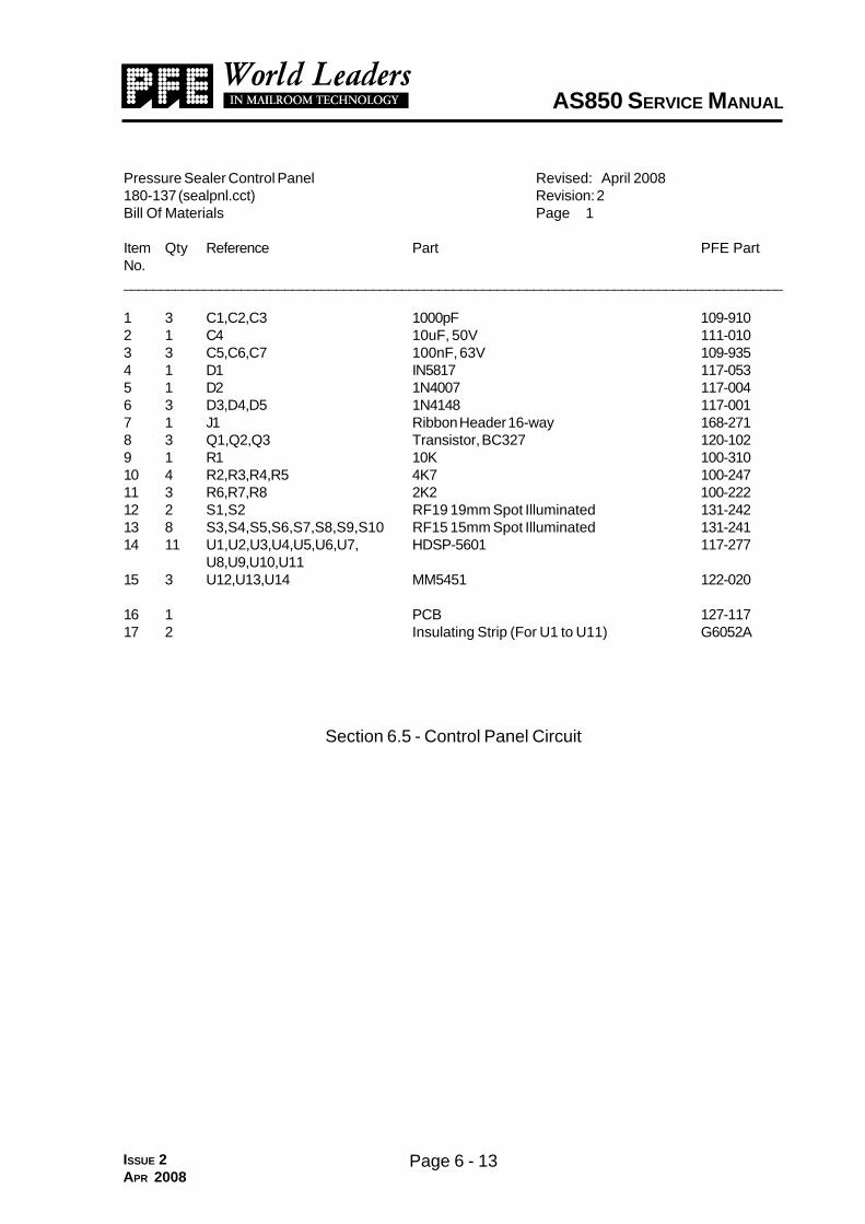
Pressure Sealer Control Panel Revised: April 2008180-137 (sealpnl.cct) Revision: 2Bill Of Materials Page 1
Item Qty Reference Part PFE PartNo.__________________________________________________________________________________________
1 3 C1,C2,C3 1000pF 109-9102 1 C4 10uF, 50V 111-0103 3 C5,C6,C7 100nF, 63V 109-9354 1 D1 IN5817 117-0535 1 D2 1N4007 117-0046 3 D3,D4,D5 1N4148 117-0017 1 J1 Ribbon Header 16-way 168-2718 3 Q1,Q2,Q3 Transistor, BC327 120-1029 1 R1 10K 100-31010 4 R2,R3,R4,R5 4K7 100-24711 3 R6,R7,R8 2K2 100-22212 2 S1,S2 RF19 19mm Spot Illuminated 131-24213 8 S3,S4,S5,S6,S7,S8,S9,S10 RF15 15mm Spot Illuminated 131-24114 11 U1,U2,U3,U4,U5,U6,U7, HDSP-5601 117-277
U8,U9,U10,U1115 3 U12,U13,U14 MM5451 122-020
16 1 PCB 127-11717 2 Insulating Strip (For U1 to U11) G6052A
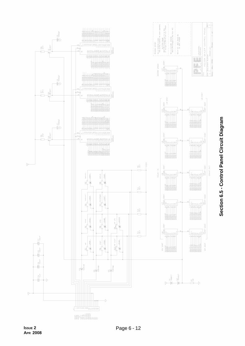
Section 6.5 - Control Panel Circuit
ISSUE 2APR 2008

Page 6 - 14ISSUE 2JUN 2006

Page 6 - 15
AS850 PRESSURE SEALER SERVICE MANUAL
ISSUE 2JUN 2006
AC Motor Control Revised: December 1997180-664 (127-182.cct) Revision: 1Bill Of Materials December 1997 Page 1
Item Qty Reference Part PFE Part No.__________________________________________________________________________________________
1 1 J1 Connector, MTA .156", 10-way 168-1702 1 J2 Connector, JST Header, 2-way 168-8523 1 SN1 Snubber, 0.1uF, 100R 106-8054 1 R1 2K2 100-2225 1 R2 1K0 100-2106 1 RV1 Varistor, 275v, 45 Joules 106-9257 1 D1 LED, Green, 5mm Bead 117-2668 1 D2 Bridge, 1A, 200v, W02 117-3019 1 SSR1 Relay, S/S MP240D4 130-070
10 1 PCB 127-162
Section 6.6 - AC Motor Control Circuit

Sec
tion
6.7
Out
put S
tack
er P
CB
(Opt
iona
l)
Page 6 - 16ISSUE 2JUN 2006

Sec
tion
6.8
Out
put S
tack
er W
iring
Dia
gram
ISSUE 2JUN 2006
Page 6 - 17

Sec
tio
n 6
.9 -
Mac
hin
eW
irin
g D
iag
ram
ISSUE 6JUL 2009
Page 6 - 18

Page 6 - 19
AS850 SERVICE MANUAL
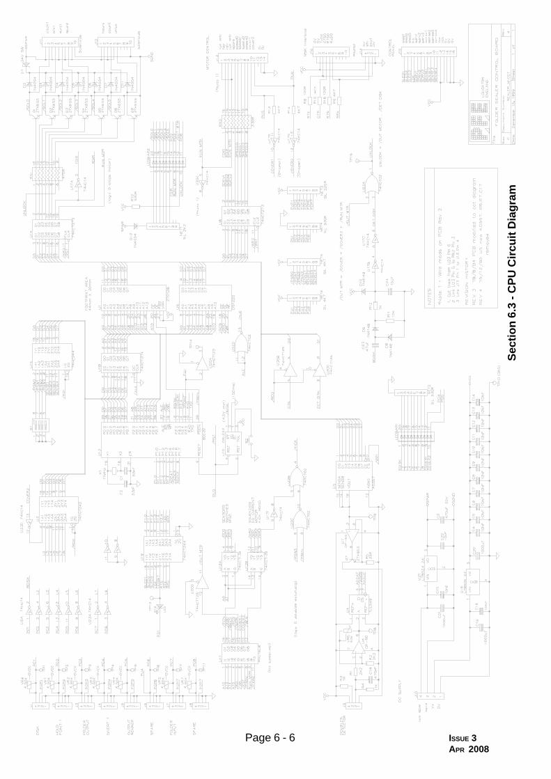
6.10 PRESSURE SEALER CIRCUIT DESCRIPTIONS
CPU CIRCUIT BOARDThe CPU board comprises the following main blocks:-
1. DC supply regulationU21 and the associated components provide a 24V, 2A series regulated dc supply for
the solenoids. U16 and associated components provide the 5V, 2A series regulated supplyfor the logic components. Both U21 and U16 have thermal shutdown protection. The 0-voltreference of the two supplies are commoned at the speed control/psu board only ,where theraw supplies are generated, to minimise noise.
2. MicrocomputerThe microcomputer block consists of U13 (microprocessor), U18 (address latch), U1
(eprom), U9 ( battery backed ram) and U10 (microprocessor supervisor / watchdog). Ad-dress decoding is acheived with U11 (pal) and U12. U11 also provides battery backed ramprotection and safety interlock logic. The microprocessor clock is derived from crystal X1.
3. Sensor interfaceSensors signals are fed to U2,U7 (schmitt inverters) and read by the processor via U3.
LEDBAR1 displays the input sensor states.
4. Doubles detectionDoubles detection circuitary consists of U6 (input amplifier), U4 (a to d converter), U5 (d
to a converter) and U7,Q7 (voltage controlled current source).
5. Solenoid interfaceSolenoid outputs are controlled via U14 (octal latch), RN1 (current limiting resistor
network), Q1 thru Q8 (output transistors), and D1 thru D11 (protection diodes). LEDBAR2displays the solenoid output states.
6. Control panel interfaceDisplay data is buffered by U19 (buffer) and written serially to the control panel. The
switch positions are sensed via U14 (buffer) .
7. Motor control interfaceThe motor control interface to the microcomputer is provided by U6 (latch) and U14
(latch). Covers are detected via U17,U23 (schmitt inverters) and U3 (buffer).
8. Safety inter-lock circuitryThe safety-interlock circuit monitors the slotted disk and covers signals and generates
the UNLOCK solenoid output. This output only goes true if the motor has been told to stopand the slotted disk has come to rest.
ISSUE 2APR 2008
Page 6 - 20
AS850 SERVICE MANUAL
The disk detection circuit comprises C23, D8, D9, R11, R12, D10, C24, U17B and U17C.The resulting output DET DISK is read by the processor via U20C (buffer). The inter-locklogic is achieved with U11 and U22A.
9. Serial interfaceSerial interface is provided by protection resistors R8, R9, R15, R16 and read by the
processor via U19 (buffer) and U20B (buffer).
___________________________________________
CONTROL PANEL CIRCUIT BOARD
Display data is written serially to U12,U13 and U14 (display drivers) by the CPU board.The display drive chips switch current to the eleven seven segment displays, U1 thru U11 andthe spot leds in switch S1 thru S9. The led current reference is set by D1, D2, R6, R7, andR8. Transistors Q1, Q2 and Q3 are configured to provide this current reference.
Switches S1 thru S9 are connected in a ‘matrix’ configuration. The CPU board de-tects key presses by driving each ‘column’ output low , in turn, and reading the ‘row’ signals.
____________________________________________
SPEED CONTROL / PSU CIRCUIT BOARD
The Speed Control / PSU Board comprises the following main blocks :-
1. Mains filteringThe CPU unregulated mains supply is filtered by C9, L3, C8 and C10. The Speed
Control circuitry is filtered separately by C17, L2, C11 and C12. Transient suppression isprovided by RV2.
2. CPU unregulated supplyUnregulated 17V dc and 34V dc supplies are generated using T2 (transformer), BR1
(bridge), C7, C22 (reservoirs capacitors) and R4 (voltage dropper). Thermistors RT3 andRT4 provide the protection.
3. Control interfaceU1 and U3 (opto-isolators) interface with the CPU board and provide mains isolation
.
ISSUE 2APR 2008

Page 6 - 21
AS850 SERVICE MANUAL
4. Speed Control The speed control circuit consists of the following sub-blocks:
- PSU block : T1, BR2, C4, D10, C14, C3. Protected by thermistors RT1 and RT2- Start/Stop,Direction control and braking relays K2 and K3- Braking resistors R39 and R42- Mains rectifying and phase angle switching : D1, D2, SCR1, SCR2 with free-wheeling diode D18- Phase angle reference cct : D19, R30, C21, Z1, R24, R31, R32- Phase angle control comparators and thyristor drive : U4D and U4A- Voltage feed-back and summing amplifier : U2B and associated components- Buffer amplifier : U4C- IR compensation cct : U2C and associated components- Current trip cct : U2A and associated components- Current limiting cct : U2D and associated components- Relay drivers : Q3, Q4 and protecting diodes D7 and D8- Low frequency switching noise filter : L1 and C16- Transient suppression : RV1
Adjustments
- Maximum speed adjustment : VR3- Minimum speed adjustment : VR6- Current limit adjustment : VR4- Current trip adjustment : VR5- IR compensation adjustment VR1
5. Safety relayIf either cover switch is opened safety relay K1 removes power to the motor speed
control circuit.
ISSUE 2APR 2008

Page 6 - 22
AS850 SERVICE MANUAL
Blank Page
ISSUE 2APR 2008