section 701 culvert pipe, entrance pipe, storm sewer pipe ... amd... · 701—1 section 701 ⎯...
TRANSCRIPT
701—1
SECTION 701 ⎯ CULVERT PIPE, ENTRANCE PIPE, STORM SEWER PIPE, AND EQUIVALENTS
701.01 DESCRIPTION. Furnish and install culvert pipe, entrance pipe, and storm sewer pipe. Use units conforming to the dimensions, fabrication, material, and strength requirements for the type (culvert, entrance, or storm sewer), diameter, cover height, and pH level the Contract specifies. This work may include removing pipe, and relaying pipe. 701.02 MATERIALS.
701.02.01 Pipe. Conform to Section 810 for the following:
1) Reinforced Concrete Circular Pipe. 2) Reinforced Concrete Horizontal Elliptical Pipe. 3) Corrugated Steel Circular Pipe with Helical Lock Seam or Helical Welded Seam. 4) Corrugated Steel Circular Pipe with Longitudinal Riveted or Spot Welded Seam. 5) Corrugated Steel Pipe Arch. 6) Corrugated Aluminum Alloy Circular Pipe with Helical Lock Seam. 7) Corrugated Aluminum Alloy Pipe Arch. 8) High Density Polyethylene (HDPE) Pipe (Thermoplastic). 9) Polyvinyl Chloride (PVC) Pipe (Thermoplastic). 10) Spiral Rib Steel Circular Pipe. 11) Spiral Rib Steel Pipe Arch. 12) Spiral Rib Aluminum Alloy Circular Pipe. 13) Spiral Rib Aluminum Alloy Pipe Arch.
701.02.02 Structural Plate Pipe. Conform to Section 809 for the following:
1) Corrugated Aluminum Alloy Circular Pipe with Longitudinal Seam with
Aluminum or Steel Bolts. 2) Corrugated Aluminum Alloy Circular Pipe Arch with Longitudinal Seams with
Aluminum or Steel Bolts. 3) Corrugated Steel Pipe Arch with Longitudinal Seams with Steel Bolts. 4) Corrugated Steel Pipe with Longitudinal Seams with Steel Bolts.
701.02.03 Joint Materials.
A) Mortar Joints. Conform to Section 801 for cement and Section 804 for mortar
sand. B) Asphalt Mastic Joint Sealing Compound. Conform to Subsection 807.03.04. C) Rubber Gaskets. Conform to Subsection 807.03.04. D) Butyl Rubber Sealants. Conform to Subsection 807.03.04. E) Elastomeric Seals. Conform to ASTM F477. F) Couplings for Thermoplastic Pipe. Conform to Section 810. G) Cleated and Non-Cleated, Integral Welded Bell Coupler with Gaskets.
Conform to Section 810.
701.02.04 Bedding Materials. Use No. 8 aggregate, No. 9-M aggregate, or a fine aggregate conforming to Subsection 804.08 for bedding material. Do not use a DGA or gravel base material for bedding material.
701—2
701.02.05 Backfill Materials. A) Granular Backfill.
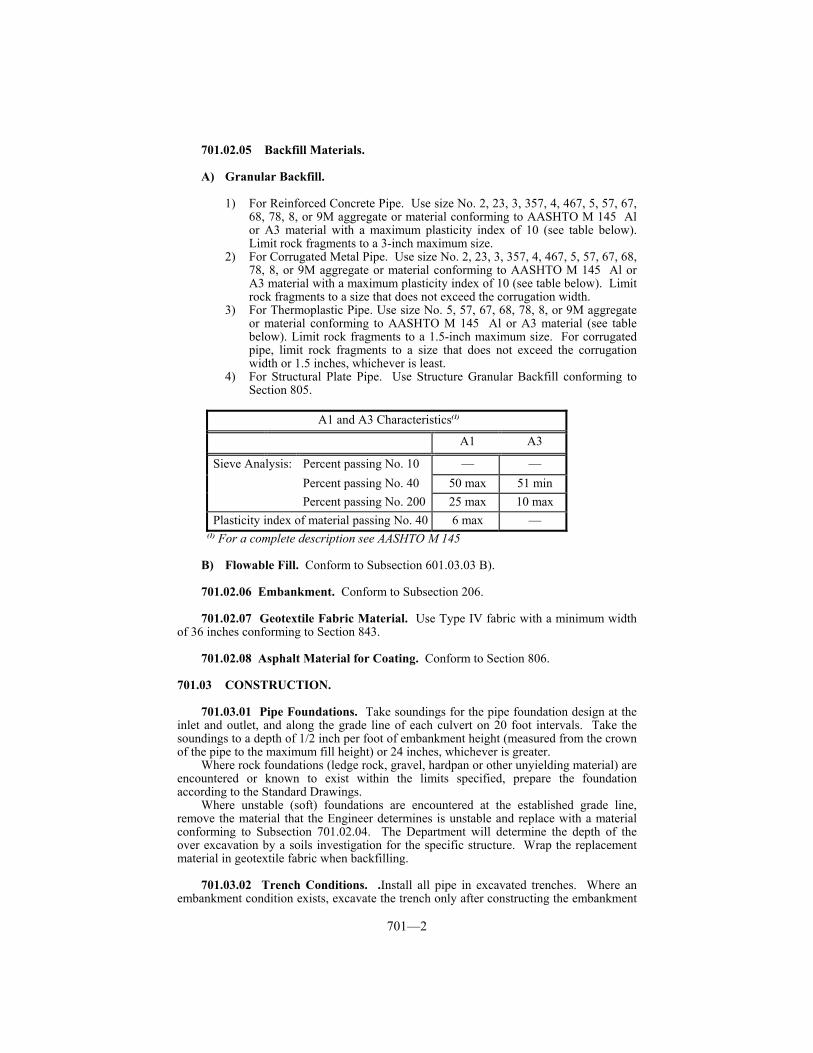
1) For Reinforced Concrete Pipe. Use size No. 2, 23, 3, 357, 4, 467, 5, 57, 67, 68, 78, 8, or 9M aggregate or material conforming to AASHTO M 145 Al or A3 material with a maximum plasticity index of 10 (see table below). Limit rock fragments to a 3-inch maximum size.
2) For Corrugated Metal Pipe. Use size No. 2, 23, 3, 357, 4, 467, 5, 57, 67, 68, 78, 8, or 9M aggregate or material conforming to AASHTO M 145 Al or A3 material with a maximum plasticity index of 10 (see table below). Limit rock fragments to a size that does not exceed the corrugation width.
3) For Thermoplastic Pipe. Use size No. 5, 57, 67, 68, 78, 8, or 9M aggregate or material conforming to AASHTO M 145 Al or A3 material (see table below). Limit rock fragments to a 1.5-inch maximum size. For corrugated pipe, limit rock fragments to a size that does not exceed the corrugation width or 1.5 inches, whichever is least.
4) For Structural Plate Pipe. Use Structure Granular Backfill conforming to Section 805.
A1 and A3 Characteristics(1)
A1 A3
Sieve Analysis: Percent passing No. 10 — — Percent passing No. 40 50 max 51 min Percent passing No. 200 25 max 10 max
Plasticity index of material passing No. 40 6 max — (1) For a complete description see AASHTO M 145
B) Flowable Fill. Conform to Subsection 601.03.03 B). 701.02.06 Embankment. Conform to Subsection 206.
701.02.07 Geotextile Fabric Material. Use Type IV fabric with a minimum width
of 36 inches conforming to Section 843.
701.02.08 Asphalt Material for Coating. Conform to Section 806. 701.03 CONSTRUCTION.
701.03.01 Pipe Foundations. Take soundings for the pipe foundation design at the inlet and outlet, and along the grade line of each culvert on 20 foot intervals. Take the soundings to a depth of 1/2 inch per foot of embankment height (measured from the crown of the pipe to the maximum fill height) or 24 inches, whichever is greater.
Where rock foundations (ledge rock, gravel, hardpan or other unyielding material) are encountered or known to exist within the limits specified, prepare the foundation according to the Standard Drawings.
Where unstable (soft) foundations are encountered at the established grade line, remove the material that the Engineer determines is unstable and replace with a material conforming to Subsection 701.02.04. The Department will determine the depth of the over excavation by a soils investigation for the specific structure. Wrap the replacement material in geotextile fabric when backfilling.
701.03.02 Trench Conditions. .Install all pipe in excavated trenches. Where an embankment condition exists, excavate the trench only after constructing the embankment
701—3
according to Section 206 to an elevation equal to, or greater than, the minimum cover height of the pipe.
701.03.03 Pipe Bedding. A) Reinforced Concrete Pipe. Construct bedding according to the Standard
Drawings and this section.
1) Type 1 Installation. When working on a rock foundation, place bedding to a depth of 6 inches or equal to Bc/12, the pipe diameter in inches divided by 12, whichever is greater. For all other foundations, place a minimum of 4 inches of bedding. Shape the bedding to conform to the invert shape throughout the entire width and length of the proposed structure. Compact the bedding, but leave the center third of the pipe diameter (Bc/3) uncompacted. Place and compact additional bedding material in lifts 6 inches or less to an elevation of 0.30 the culvert diameter.
2) Type 4 Installation. When working on a rock foundation, place bedding to a depth of 6 inches or equal to Bc/12, the pipe diameter in inches divided by 12, whichever is greater. For all other foundations, place a minimum of 4 inches of bedding.
B) Corrugated Metal, Thermoplastic, and Structural Plate Pipe. Place and
compact bedding to provide 4 inches of bedding below the outside invert of the pipe after shaping. Shape the bedding to conform to the invert shape throughout the entire width and length of the proposed structure. Place and compact additional bedding material in lifts 6 inches or less to an elevation of 0.30 the culvert diameter.
701.03.04 Pipe Hauling, Handling, and Installation. Furnish a copy of the
manufacturer’s handling and installation procedures to the Engineer before beginning work. Ensure that pipe structures do not sustain damage during loading, unloading, placement on the bedding, compaction of the backfill, by movement of excessively heavy equipment over the fill, or by any other forces that may cause damage. Repair or replace damaged structures as the Engineer directs. Remove and replace any structure that is not constructed to true alignment or shows undue settlement after installation, or is otherwise damaged, without additional compensation.
A) Reinforced Concrete Pipe. Install the pipe beginning at the outlet end of the culvert, with the bell or groove end laid upgrade. Extend successive spigot or tongue ends fully into each adjoining bell or groove. When the pipe includes markings to designate the top and bottom, lay the pipe so the mark is less than 5 degrees from the vertical plane throughout the longitudinal axis of the pipe. Cover all lift holes after installing the pipe by the following:
1) Coat an area 8 inches or wider than the holes on the outside of the pipe with
an asphalt coating material; 2) Place a piece of sheet metal 4 inches or wider than the holes and shaped to
conform to the outer pipe diameter over each hole; and 3) Apply an additional coating of asphalt material over the entire area of
previously applied metal. When desired, use precast lift hole plugs instead of the asphalt and sheet metal.
B) Corrugated Metal Pipe.
1) Asphalt Coating. Apply according to AASHTO M-190.
701—4
2) Transporting and Handling. Transport and handle coated pipe using equipment and methods that prevent damage to the coating. When storing pipe on the project, keep it supported above the ground using wooden timbers or pallets. Repair minor damage to exterior and interior coating with asphalt coating material according to AASHTO M 243 or as the Engineer directs before installing the pipe. Repair significant damage and coating deficiencies at the pipe fabrication site as the Engineer directs. Significant damages include spalled coating on the interior of the pipe, uncoated areas due to manufacturing error, and insufficient coating thickness on the interior or exterior of the pipe.
At all times during construction, use every precaution to prevent damage to the protective coating. Do not allow any metal tools or heavy objects to unnecessarily come in contact with the finished coating. Repair any damage to the protective coating from any cause during installation and before final acceptance as the Engineer directs.
3) Installing. Assemble according to the manufacturer’s instructions. Install in the bed starting at the downstream end. When using corrugated metal pipe with paving material, install the pipe with paving material along the bottom centerline or flowline. Construct struts and vertical elongation of corrugated metal pipe as specified in the Plans. Remove the struts only after completing the embankment over the structure.
C) Thermoplastic Pipe. Handle thermoplastic pipe according to the
manufacturer’s recommendations. Provide a manufacturer’s technical representative to assist in the installation of the pipe when the Engineer requests.
D) Structural Plate Pipe. Install the pipe according to the manufacturer's
specifications and installation procedures. When the Engineer requests, provide a manufacturer's technical representative to assist in pipe construction. Do not place backfill until all plates in a ring are complete and all bolts in the structure are tightened.
701.03.05 Joints. Provide soil tight joints. Wrap all pipe joints with a geotextile
fabric when their inner diameters are 54 inches and greater.
A) Reinforced Concrete Pipe. Use only one type of jointing materials system throughout each single structure. Construct joints for reinforced concrete pipe with one of the following options.
1) Mortar Joints. Use a mixture containing one part cement and 2 parts sand.
Use enough water, not exceeding 5 1/2 gallons per sack of cement, to product a stiff, workable mortar. Thoroughly clean and wet the ends of the pipe before joining them. Place the mortar in the lower half of the bell or groove section that has been laid, and apply mortar to the upper half of the spigot or tongue of the pipe that is being laid. Insert the spigot or tongue in the bell or groove of the pipe already laid, pull the joint tight, and ensure that the inner surfaces of the abutting sections are flush and even. After laying a section of the pipe and before laying the succeeding section, thoroughly plaster the lower portion of the bell or groove of the preceding section on the inside with mortar to such a depth to ensure a smooth joint between the abutting sections. Fill the remainder of the joint flush with mortar. Finish the inside of the joint and wipe smooth around the full circumference. After the initial set, protect the mortar from air and sun with a burlap cover, or permanently backfill.
2) Asphalt Mastic Joints. Immediately before installation, apply the asphalt mastic joint sealing compound to the ends of the pipe section in the same manner as mortar joints except precoat all joining surfaces. Precoat with the
701—5
manufacturer’s recommended primer or an approved emulsified asphalt. Apply enough sealer to extrude a bead of the compound from the joint on the inside and outside of the pipe when completely meshed. Remove excess material to form a smooth, flush joint.
3) Rubber Gaskets. In addition to the requirements of Subsection 701.02, use a pipe section conforming to AASHTO M 315. Use the gasket manufacturer’s recommended cement and lubricant. Snugly fit the rubber gasket in the beveled surface of the tongue and groove ends of the sections to form a flexible seal under all conditions of service.
4) Butyl Rubber Sealants. In addition to the requirements of Subsection 701.02, use pipe with a joint design conforming to AASHTO M 198.
When a joint is located 12 feet or less from the outlet on a 3:1 or steeper
slope, provide a tied joint according to the Standard Drawings.
B) Corrugated Metal Pipe. Construct joints using a band with annular corrugations and a bolt, bar and strap connection. Use a minimum nominal band width of 12 inches for all pipe diameters 54 inches and smaller. Use a two-piece band with a minimum nominal width of 20 inches for all pipe diameters greater than 54 inches. Manufacture the band from the same base materials as the pipe. The pipe bands may be up to two gauges lighter than the pipe it is joining, with a minimum gauge thickness of 16. The Department may allow dimple band connections for field cut pipe. Install the connecting bands according to the manufacturer's written recommendations.
C) Thermoplastic Pipe. Use an integral bell and spigot type with elastomeric seal
joints. When a joint is located 12 feet or less from the outlet on a 3:1 or steeper slope, use a cleated integral bell locking joint or a standard coupling aided by two #14 by 2-inch galvanized sheet metal screws inserted through the coupling into the corrugation crest 2 inches apart circumferentially at the bell and spigot coupler’s quarter points.
701.03.06 Initial Backfill. Locate a suitable backfill source for each project. For
backfill containing soils, have an AASHTO accredited lab classify the material, run a standard proctor, and certify that the material conforms to the specified granular material. Keep the material certification on file and available to the Engineer upon request.
Place the backfill material in a trench condition as the Contract specifies. Use 6-inch lifts and ensure the backfill is compacted to not less than 95 percent of the maximum density as determined according to KM 64-511.
When the top of the pipe is within one pipe diameter of the subgrade, backfill with flowable fill to an elevation of one foot above the pipe from the outside edge of shoulder or back of curb to outside edge of shoulder or back of curb as applicable. When installing under existing pavement, backfill with flowable fill to the subgrade elevation.
When granular backfill is used, the surrounding conditions are not similar in gradation, and the pipe is located within the area bounded by the centerline and a distance 25 feet outside the edge of shoulder or back of curb, as applicable, wrap the bedding and granular backfill in geotextile fabric. The Department will not require geotextile fabric for entrance pipe. When geotextile fabric is required according to this section or the Engineer’s direction, install according to Section 214.
When the Contract specifies, perform quality control testing to verify compaction according to KM 64-412. The Department may verify the density results at any time of the duration of the project.
A) Reinforced Concrete Pipe. 1) Type 1 Installation. When the top of the pipe is not within one pipe
diameter of the subgrade, backfill with granular backfill, additional bedding
701—6
material, or flowable fill from the top of the bedding to an elevation equal to 1/2 the pipe diameter, and either granular backfill, flowable fill, or embankment material in 6-inch lifts to an elevation of one-foot above the pipe.
2) Type 4 Installation. Backfill from the top of the bedding with granular backfill, flowable fill, or embankment material in 6-inch lifts to an elevation of one-foot above the pipe. The Department will allow Type 4 installations for median drains and pipe installations located 35 feet or more from the edge of shoulder, back of curb, or any paved surface.
B) Corrugated Metal, Thermoplastic, and Structural Plate Pipe. When the top
of the pipe is not within one pipe diameter of the subgrade, backfill with either granular backfill or flowable fill to an elevation at least one foot above the top of the pipe.
701.03.07 Construction Loads. Do not allow construction equipment or traffic to
travel over the top of the structure material until the fill is compacted to a minimum depth of 48 inches over the top of the structure. The Engineer may require temporary cover where the final grade is less than 48 inches. The Engineer may raise but will not lower the minimum cover based on the pipe manufacturer’s recommendations.
701.03.08 Testing of Pipe. The Engineer will visually inspect all pipe. The Department may require camera or mandrel testing, KM 64-114, for any pipe when deflection, cracking, joint faulting, or any other interior damage is suspected. If the pipe shows damage, repair or replace as the Engineer directs. If the pipe shows deflection of 10 percent or greater, remove and replace the pipe. If the pipe shows deflection greater than 5 percent but less than 10 percent, the Department will allow the pipe to remain in place at a reduced unit price. Do not pave over any pipe until inspection and any required testing is completed. When paving will not be delayed by the wait, test pipe 30 days or more after backfilling is completed.
701.03.09 End Structures. Construct anchors, concrete headwalls, and other end
structures specified in the Plans according to Section 610, Section 710, and the Standard Drawings.
701.03.10 Extensions to Existing Culvert Pipe and Entrance Pipe. Construct pipe
extensions for culvert pipe, entrance pipe, and equivalent pipe arches according to this section and the Contract. Remove the necessary portions of the existing structure to provide a neat junction with the extension. Do not damage the portion that is to remain in service. Remove all silt and debris that has accumulated in the remaining portion of the structure for a distance back equal to twice the pipe diameter or as the Engineer directs.
701.03.11 Removing Pipe, Removing and Relaying Pipe. Remove all pipe designated for removal in the Contract. Safely store all reusable pipe. Restore or replace, any pipe designated for reuse that incurs damage or destruction through faulty handling. Relay all removed pipe the Contract designates to be relayed. Where pipe is not to be relayed, fill the area to the existing ground line according to 207.03.
The Department will retain ownership of reusable pipe that is not to be relaid in areas on the project. Unless the Engineer directs otherwise, deliver all reusable pipe not relayed on the project to the designated maintenance facility in the county where the project is located. Take ownership of and remove from the project all pipe that is not designated for reuse or salvage. 701.04 MEASUREMENT.
701.04.01 Culvert Pipe. The Department will measure the quantity in linear feet
701—7
from end-to-end along the bottom or pipe invert of the installed structure. The Department will include bends, elbows, crosses, tees, reducers, laterals, wyes, and other shapes in the pipe lengths measured. The Department will not measure joint materials and bedding materials for payment and will consider them incidental to this item of work. The Department will not measure replacement of damaged pipe for payment and will consider it incidental to this item of work. The Department will not measure for payment the providing of a manufacturer’s technical representative to assist in the construction of the pipe and will consider it incidental to this item of work.
701.04.02 Culvert Pipe Equivalent. Culvert Pipe Equivalent includes elliptical culvert pipe and culvert pipe arches. The Department will measure the quantity in linear feet according to Subsection 701.04.01.
701.04.03 Entrance Pipe. The Department will measure the quantity in linear feet according to Subsection 701.04.01.
701.04.04 Entrance Pipe Equivalent. Entrance Pipe Equivalent includes elliptical
entrance pipe and pipe arches. The Department will measure the quantity in linear feet according to Subsection 701.04.01.
701.04.05 Storm Sewer Pipe. The Department will measure the quantity in linear feet according to Subsection 701.04.01.
701.04.06 Storm Sewer Pipe Equivalent. Storm Sewer Pipe Equivalent includes
elliptical storm sewer pipe and storm sewer pipe arches. The Department will measure the quantity in linear feet according to Subsection 701.04.01.
701.04.07 Testing. When testing is performed due to a disagreement with a visual
inspection and the Department is in error, the Department will measure the quantity as Extra Work according to Subsection 104.03.
701.04.08 Geotextile Fabric, Type IV. The Department will measure the quantity
in square yards. 701.04.09 Flowable Fill. The Department will not measure the quantity for payment
and will consider it incidental to the pipe bid item. When the Engineer determines that it is necessary and to the Department’s benefit to excavate beyond the typical excavation limits shown in the Standard Drawings, the Department will measure the quantity of flowable fill required for backfill outside the typical excavation limits as Extra Work.
701.04.10 Embankment-In-Place. The Department will measure the quantity
where there is unstable foundation material in excess of 3 times the width of outside diameter of the pipe or the width of the outside diameter plus 4 feet, whichever is less, in cubic yards according to Subsection 206.04.
701.04.11 Roadway Excavation. The Department will measure the quantity for removal of unstable foundation material in excess of 3 times the width of outside diameter of the pipe or the width of the outside diameter plus 4 feet, whichever is less, in cubic yards according to Subsection 204.04.
When using Special Design, the Department will measure the quantity by the length of the trench the Contract specifies or as the Engineer directs. The Department will not measure backfilling the trench with bedding material for payment and will consider it incidental to this item of work.
The Department will not measure any other excavation and will consider it incidental to Culvert Pipe, Entrance Pipe, and Storm Sewer Pipe.
701.04.12 Pipe Undercut. The Department will measure the quantity for removal of
701—8
unstable foundation material or bedded rock in cubic yards up to a maximum of 3 times the width of the outside diameter of the pipe or the width of the outside diameter of the pipe plus 3 feet, whichever is less, and to a depth of up to 2 feet. The Department will measure the quantity at a depth of greater than 2 feet as Extra Work according to Subsection 109.04.
701.04.13 Structure Excavation Unclassified. When the Engineer changes the pipe’s plan length or location and causes the required excavation to increase more than 10 percent above the original average excavation per yard, the Department will measure the quantity in cubic yards according to Subsection 603.04. When the Department requires a substantial increase in excavation, submit verification to the Engineer before starting excavation. The Engineer will then measure the quantity of excess volume. The Department will not consider the excavation of unstable material from the foundation when determining the percentage of material increase.
701.04.14 Removing Pipe. The Department will measure the quantity in linear feet of net laying length per section. The Department will measure bends, elbows, crosses, tees, reducers, laterals, wyes, and other shapes in linear feet along the central axis of the unit. The Department will not measure furnishing and placing any borrow material necessary to refill the area to the original ground line for payment and will consider it incidental to this item of work. When the Department retains ownership, the delivery of the pipe to the designated maintenance facility will not be measured for payment and is considered incidental to this item of work.
Unless design quantities are included in the Contract, the Department will not measure pipe within the typical section for payment and will consider it incidental to roadway excavation.
701.04.15 Removing and Relaying Pipe. The Department will measure the
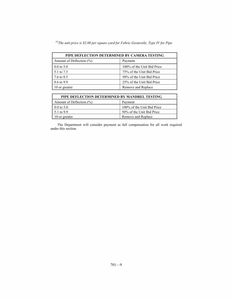
quantity according to Subsection 701.04.01. The Department will not measure sections that are damaged or broken for payment and will consider them incidental to this item of work. The Department will not measure furnishing and placing any borrow material necessary to refill the area to the original ground line for payment and will consider them incidental to this item of work. When the Department retains ownership, the delivery of the pipe to the designated maintenance facility will not be measured for payment and is considered incidental to this item of work. 701.05 PAYMENT. The Department will make payment for the completed and accepted quantities under the following: Code Pay Item Pay Unit 00460-00482 Culvert Pipe, Size Linear Foot 00490-00512 Culvert Pipe Equivalent, Size Linear Foot 00439-00445 Entrance Pipe, Size Linear Foot 00450-00454 Entrance Pipe Equivalent, Size Linear Foot 00520-00542 Storm Sewer Pipe, Size Linear Foot 00551-00572 Storm Sewer Pipe Equivalent, Size Linear Foot 02600 Fabric-Geotextile, Type IV for Pipe Square Yard(2) 02230 Embankment-In-Place See Subsection 206.05 02200 Roadway Excavation See Subsection 204.05 02219 Pipe Undercut Cubic Yard(1) 02203 Structure Excavation, Unclassified See Subsection 603.05 01310 Remove Pipe Linear Foot 01312 Remove and Relay Pipe Linear Foot
(1) The unit price is $20.00 per cubic yard for pipe undercut 2 feet in depth or less. The Department will pay for pipe undercut exceeding a depth of 2 feet, as specified in Subsection 109.04.
701—9
(2)The unit price is $2.00 per square yard for Fabric-Geotextile, Type IV for Pipe
PIPE DEFLECTION DETERMINED BY CAMERA TESTING Amount of Deflection (%) Payment 0.0 to 5.0 100% of the Unit Bid Price 5.1 to 7.5 75% of the Unit Bid Price 7.6 to 8.5 50% of the Unit Bid Price 8.6 to 9.9 25% of the Unit Bid Price 10 or greater Remove and Replace
PIPE DEFLECTION DETERMINED BY MANDREL TESTING
Amount of Deflection (%) Payment 0.0 to 5.0 100% of the Unit Bid Price 5.1 to 9.9 50% of the Unit Bid Price 10 or greater Remove and Replace The Department will consider payment as full compensation for all work required
under this section.
702—1
SECTION 702 ⎯ SLOTTED DRAIN PIPE 702.01 DESCRIPTION. Furnish and place slotted drain pipe of the specified size and wall thickness, at the locations specified in the Plans or designated by the Engineer. 702.02 MATERIALS.
702.02.01 Slotted Drain Pipe. Conform to Subsection 810.04.05.
702.02.02 Coupling Bands. Provide coupling bands recommended by the manufacturer. 702.03 CONSTRUCTION. Conform to Section 701.03 and the Standard Drawings for excavation of the pipe trench, pipe placing, and backfill.
Do not begin installing the slotted drain pipe until paving of the traffic lanes adjacent to the pipe has been completed at the location where the pipe is to be installed.
Before backfilling, plug the upgrade end of the slotted drain pipe with a metal cap or by other methods the Engineer approves.
During the backfilling operations and paving operations adjacent to the slot, cover the slot to prevent infiltration of material into the pipe, and do not damage the slotted drain pipe. Remove foreign material that enters the pipe, and repair any damage to the slotted drain pipe to the satisfaction of the Engineer, at no expense to the Department. 702.04 MEASUREMENT.
702.04.01 Slotted Drain Pipe. The Department will measure the quantity in linear feet. The Department will not measure structure excavation, backfill, plugging, removal of foreign material, or coupling bands for payment and will consider them incidental to this item of work. 702.05 PAYMENT. The Department will make payment for the completed and accepted quantities under the following: Code Pay Item Pay Unit 00980-00985 Slotted Drain Pipe, Size Linear Foot
The Department will consider payment as full compensation for all work required under this section.
703—1
SECTION 703 ⎯ SLOPE PROTECTION AND CHANNEL LINING
703.01 DESCRIPTION. Furnish and place the specified material for a protective covering for slopes or linings in channels and ditches, according to the Contract or as the Engineer directs. Slope protection includes the following types: Reinforced Concrete Slope Wall, Cyclopean Stone Riprap, and Crushed Aggregate Slope Protection. Channel lining includes the following types: Class IA (mattress units), Class II, Class III, and Class IV (prepared from rock excavation). 703.02 MATERIALS.
703.02.01 Concrete. Conform to Subsection 601.02 and 601.03. 703.02.02 Steel Reinforcement. Conform to Section 811. 703.02.03 Coarse Aggregate. Conform to Section 805. 703.02.04 Fine Aggregate. Conform to Section 804, natural sand. 703.02.05 Joint Material. Conform to Section 807, preformed joint filler. 703.02.06 Drain Pipe. Conform to Section 810. 703.02.07 Mattress Units for Channel Lining Class IA. Conform to Section 813.
703.02.08 Anchor Bars for Channel Lining, Class IA. Use Grade 40 or better
steel reinforcing bars conforming to the dimensions shown on the Standard Drawings. The Engineer will base acceptance of the anchor bars on visual inspection.
703.02.09 Geotextile Fabric. Use Type I fabric conforming to Section 843.
703.03 CONSTRUCTION.
703.03.01 Slope Protection.
A) General. Do not allow slopes on which protection is placed to be steeper than the natural angle of repose. Shape the slopes to the slope and contour indicated or as the Engineer directs. Use slope templates in determining the slope. Bring depressions to the required slope line with fill material moistened and compacted as the Engineer directs.
Unless solid rock is encountered, begin all slope protection, except crushed aggregate slope protection, in a trench 2 feet below the natural ground. Where solid rock is encountered, stop the lower terminus of the slope protection at the solid rock line unless the Engineer directs otherwise.
Unless solid rock is encountered, underlay cyclopean stone riprap, crushed aggregate slope protection and all classes of channel lining with geotextile fabric.
B) Reinforced Concrete Slope Wall. Use 6-inch slope walls on slopes 1/4 to one or flatter.
Construct porous aggregate underdrains at the location of all construction joints at the intervals shown on the Standard Drawings. Ensure that the porous aggregate underdrains consist of a 12-inch by 12-inch trench excavated in the earth or solid rock and filled with coarse aggregate or natural sand. Place weep holes along the toe of the reinforced concrete slope walls at a maximum of 10-foot intervals. Construct weep holes by using 4-inch diameter pipe or suitably formed 4-inch diameter holes through the walls.
Construct slope walls using Class A concrete according to Subsection
703—2
601.03. Construct slope walls using the size, position, width of sheets, length of laps, and diameter of the mesh shown on the Standard Drawings. Construct the finished slope walls with an even, smooth surface that will not show a variation from a true plane of more than 1/2-inch in 4 feet. Build warped or curved surfaces to the same degree of accuracy as plane surfaces. Cure concrete according to Subsection 601.03. After completing the slope protection, backfill excavated areas that are not filled by slope protection to the surface of the original groundline.
C) Cyclopean Stone Riprap Slope Protection. Construct cyclopean stone riprap to a minimum thickness of 2 feet measured perpendicular to the slope. The Department will allow dumping stone in place and relocating it in a manner to produce a surface of approximate regularity not varying more than 6 inches from a true plane.
D) Crushed Aggregate Slope Protection. Unless otherwise shown, place the aggregate to a depth of one foot measured perpendicular to the slope flush with the embankment slopes under the bridge; extend it from the face of the abutments or end bents across the berm and down the slope to the toe of the slope; and extend it laterally to 18 inches beyond the outer edges of the superstructure.
The Department will allow dumping the crushed aggregate in place and relocating it in a manner to produce a uniform surface varying no more than 1 1/2 inches in 4 feet from a true plane. The Department will not require hand placing except as necessary to correct irregularities exceeding the specified tolerances.
703.03.02 Channel Lining. Before placing any channel lining materials, excavate
and shape the area to receive the channel lining, so that the completed channel lining will be uniform and will conform to the designated lines, grades, and cross section.
A) Channel Lining, Classes II and III. Construct Channel Lining Classes II and III to the dimensions specified in the Plans, Standard Drawings, or as the Engineer directs. The Department will allow dumping the stone in place and relocating it in a manner to produce a surface of approximate regularity, varying no more than 3 inches from a true plane. The Department will not require hand placing except as necessary to correct any surface irregularities exceeding the specified tolerance.
B) Channel Lining, Class IV. Unless solid rock is encountered, begin the channel lining in a trench 2 feet below the natural ground or 2 feet below the channel flowline when the flowline is not lined. Where solid rock is encountered, stop the lower terminus of the slope protection at the solid rock line. Construct Channel Lining, Class IV to the minimum thickness specified in the Plans. The Department will allow dumping the stone in place and relocating it in a manner to produce a surface of approximate regularity not varying more than 6 inches from a true plane.
C) Channel Lining, Class IA. Construct according to the Standard Drawings. Set empty mattress units to the required line and grade. Use lacing wire to join the units together.
After the mattress units are set to line and grade, stretch them to remove any kinks from the mesh and to hold alignment.
Fill the mattress units with stone. Place by hand or machine to ensure good alignment. Avoid bulging of the mesh by minimizing voids between the stones. After filling a unit, close its top so that it meets the sides and ends of each mattress unit. Then, secure the top to the sides, ends, and the diaphragms with lacing wire as shown on the Standard Drawings.
When placing the mattress unit on a grade, begin placing the stone at the bottom of the slope and progress upgrade. Overfill mattress units approximately one inch to allow for settlement.
703—3
When space limitations prevent the installation of a complete mattress on the slope, cut the unit to fit in the manner the Plans specify. Drive anchor bars in place at the locations shown on the Standard Drawings when the grade is 5 percent or greater.
703.04 MEASUREMENT.
703.04.01 Reinforced Concrete Slope Walls. The Department will measure the quantity in square yards of surface area including the area of the front face of concrete placed within the trench below natural ground. The Department will not measure steel reinforcement or any excavation required for the construction of slope protection for payment, and will consider them incidental to this item of work.
703.04.02 Cyclopean Stone Riprap. The Department will measure the quantity in
tons. The Department will not measure excavation required for the construction of slope protection for payment and will consider it incidental to this item of work.
703.04.03 Crushed Aggregate Slope Protection. The Department will measure the
quantity according to Subsection 703.04.02.
703.04.04 Channel Lining, Class IA. The Department will measure the quantity in tons. The Department will not measure excavation below the upper surface of any channel lining for payment and will consider it incidental to the work. The Department will not measure anchor bars, wire mesh, lacing wire, or other material necessary to acceptably complete the wire mattress units for payment, and will consider them incidental to this item of work.
703.04.05 Channel Lining Class II. The Department will measure the quantity in
tons. The Department will not measure excavation below the upper surface of any channel lining for payment and will consider it incidental to this item of work.
703.04.06 Channel Lining Class III. The Department will measure the quantity
according to Subsection 703.04.05. 703.04.07 Channel Lining Class IV. The Department will measure the quantity
according to Subsection 204.04. 703.04.08 Geotextile Fabric. The Department will measure the quantity according to
Subsection 214.04.
703.05 PAYMENT. The Department will make payment for the completed and accepted quantities under the following: Code Pay Item Pay Unit 08014, 08016 Reinforced Concrete Slope Wall, Size Square Yard 08019 Cyclopean Stone Riprap Ton 08020 Crushed Aggregate Slope Protection Ton 02482 Channel Lining, Class IA Ton 02483 Channel Lining, Class II Ton 02484 Channel Lining, Class III Ton 02488 Channel Lining, Class IV See Subsection 204.05
The Department will consider payment as full compensation for all work required under this section.

704—1
SECTION 704 ⎯ UNDERDRAINS 704.01 DESCRIPTION. Construct underdrains of perforated pipe, non-perforated pipe, and porous aggregate. When required, construct headwalls according to Section 710, and the Standard Drawings. 704.02 MATERIALS AND EQUIPMENT.
704.02.01 Underdrain Pipe.
A) All Underdrain Pipe Except Edge Drain Outlet Pipe. Conform to Section 810 for the following:
1) Circular Reinforced Concrete Pipe. 2) Corrugated Steel Pipe, Type III. 3) Corrugated Aluminum Alloy Pipe, Type III. 4) High Density Polyethylene (HDPE) Pipe (Thermoplastic).
B) Edge Drain Outlet Pipe. Conform to Section 810 for the following:
1) Corrugated Steel Pipe, Type III. 2) Corrugated Aluminum Alloy Pipe, Type III. 3) High Density Polyethylene Pipe (HDPE), Type S (Thermoplastic). 4) Polyvinyl Chloride (PVC) Pipe (Thermoplastic) as follows:
a) Smooth. Conform to ASTM D 1785 for Schedule 40, or ASTM D
2241 for SDR 17. b) Ribbed. Conform to ASTM F 794 for series 46. c) Corrugated. Conform to ASTM F 949.
704.02.02 Coarse Aggregate. Conform to Subsection 805.08.
704.02.03 Natural Sand. Conform to Section 804. 704.02.04 Geotextile Fabric. Use Type II fabric conforming to Section 843 for
wrapping coarse aggregate. Use circular-knit geotextile conforming to ASTM D 6707 for perforated pipe socks.
704.02.05 Pipeline Inspection Camera. Provide a pipeline inspection camera for edge drains having the following:
1) Capable of recording the station, milepost, distance into the drain or other indicators of location on the video.
2) A device for measuring the distance the camera has been pushed from the end of the outlet.
3) The ability to record the distance superimposed on the video. 4) An outside diameter no greater than 3 inches. 5) Color capability with a minimum horizontal resolution of 400 lines according to
the manufacturer’s specifications. 6) Capable of being pushed in the 4-inch outlet pipes and mainline pipes for a
minimum of 280 feet, 250 feet of mainline plus outlet pipe. 7) Capable of being pushed or tractored for 1,000 feet in 8-inch or larger pipes
serving as a collector system for edge drains without headwalls. 8) A video output jack for connecting a VCR. 9) Capable of being connected to controls, including the VCR, for the pipeline
inspection equipment in the inspection vehicle.
704—2
704.02.06 VCR. Provide a VCR capable of connecting to the videooutput jack on the pipeline inspection system for recording the inspection.
704.02.07 Inspection Vehicle. Provide an inspection vehicle that will accommodate
the operation of the inspection camera and VCR, and 2 passengers. Provide a pipe inspection operator to operate the vehicle and observe the inspection. The Engineer may accompany the pipe inspection operator in the vehicle at any time.
704.02.08 Flowable Fill. Conform to Subsection 601.03.03 B).
704.02.09 Headwalls. Conform to Subsection 710.02. 704.02.10 Concrete. Conform to Subsection 601.02.
704.03 CONSTRUCTION.
704.03.01 Porous Aggregate Underdrain. Excavate the trench to the lines, grades, and section according to the Contract. Finish the bottom of the trench so that it is smooth and firm. Tamp if necessary.
After preparing the trench, place the aggregate in the trench, in loose layers not exceeding 6 inches in depth, and firmly tamp each layer in place. Use either crushed or uncrushed coarse aggregate, including pea gravel, or natural sand. Continue backfilling the trench with aggregate until the backfill reaches the compacted depth specified in the Plans. When using coarse aggregate, completely wrap the aggregate in geotextile fabric, Type II, according to Subsection 214.03. Backfill above the aggregate with soil that the Engineer approves and tamp in place in layers not exceeding 6 inches loose thickness.
704.03.02 Perforated and Non-Perforated Pipe Underdrains.
A) All Pipe Underdrains Except Pavement Edge Drains. Excavate the trench to a depth below the outside bottom of the plan underdrain elevation to allow for the placement of sufficient bedding to eliminate any irregularities in the trench bottom, and to a width of at least one foot wider than the external diameter of the pipe.
Place perforated pipe with the perforations in the invert. Join perforated sections with coupling fittings or bands. Place and compact granular backfill of Size No. 78, 8, or 9M coarse aggregate or natural sand around the pipe ensuring that the pipe is true to line and grade and the haunches are fully supported. Where perforated pipe installations outlet into open ditches provide a minimum of 8 feet of non-perforated pipe from the outlet.
For non-perforated pipe installations, place the pipe with the bell end upgrade and with open joints not exceeding 3/8 inch. Join the last 2 outlet sections.
Close the upgrade ends of all underdrain pipe installations with plugs to prevent entry of debris. Equip the outlet end of underdrain pipe with a screen.
After placing the pipe, place coarse aggregate or natural sand to a height of at least one foot above the top of the pipe. When using natural sand for backfill, wrap the perforated pipe in circular-knit geotextile fabric; when using coarse aggregate for backfill, completely wrap the aggregate in geotextile fabric, according to Subsection 214.03. Fill any remaining portion of the trench with either granular or impervious material according to the Contract or as the Engineer directs. Do not allow the minimum height of fill to be more than 2 feet above the top of the pipe, except the Engineer will allow one foot of fill from the top of the pipe to the top of subgrade in cases where 2 feet would not allow proper installation for drainage. Thoroughly compact the fill material in layers not exceeding 6 inches loose measurement. During placement of the aggregate and granular or impervious material do not damage or displace the pipe.
704—3
Encase any pipe that has less than one foot of cover at the outlet end in 6-
inch thick concrete of any class or flowable fill. Proportion the concrete or flowable fill according to Subsection 601.03.
B) Pavement Edge Drains. Construct using 4-inch diameter pipe according to Subsection 704.03.02 A), or as shown on the plans, except for the following:
1) Backfilling.
a. Fabric Wrapped Trench and Crushed Aggregate. When backfilling,
place geotextile fabric in the trench and shape to the sides and bottom of the trench without stretching the fabric. Ensure that the geotextile fabric does not pull down into the trench when placing the backfill material. Do not damage the geotextile fabric when placing the filter aggregate. Partially wrap the aggregate according to Subsection 214.03. Fold the fabric over the backfilled trench and secure.
b. Geotextile Pipe, Sock and Sand. Backfill the pipe with a natural sand conforming to Section 804. Do not use geotextile pipe, sock and sand if the pavement section is constructed with a drainage blanket.
c. Edge Drain Outlet Pipe. Encase any outlet pipe with a minimum of 6 inches of concrete or flowable fill over the top of the outlet pipe. In paved sections bring the concrete or flowable fill up to the bottom of pavement. Proportion the concrete or flowable fill according to Subsection 601.03.
2) Headwalls for Outlets. When the Contract requires outlet headwalls, the
Engineer will require adjustments to the headwalls when necessary to fit existing drainage conditions. Place precast headwalls according to Subsection 710.03.01 B). Install the headwall with a slope of 1/2 inch in one foot. When practical, place the toe of the headwall a minimum of 6 inches (one foot desirable) above the bottom of the ditch. Place crushed aggregate size No. 2 a minimum depth of 4 inches around the headwall as specified in the Contract.
3) Cored Hole Drainage Box or Cross Drain Headwall Connector. Make the connection according to Section 705. Make the cored hole drainage box connection a minimum of one foot above the bottom of the box. Attach a rodent screen to all edge drain outlet structures according to the Standard Drawings.
4) Construction Near Guardrail. When guardrail is attached to a structure, adjust the placement of the outlet pipe so that guardrail posts will not be driven within one foot of the outlet pipe. When the guardrail is not attached to a structure, adjust the placement of the outlet pipe or the guardrail so that guardrail posts will not be driven within one foot of the outlet pipe. Mark the location of the outlet with paint or other means the Engineer approves. Conduct a mandrel test after driving the guardrail posts by pushing a piece of flexible 2-inch gas pipe through the outlet pipes. Replace all damaged outlets.
5) Field Data. Visually observe the condition of each headwall. Observe the extent of debris blocking the headwall. Provide a description of the debris, the condition of the rodent screen, a description of the ditch line drainage, and the percent grade of the headwall. Take photographs of significant distresses and provide copies of the photographs to the Engineer. Describe the location of these significant distresses and the headwall type for each headwall. Record all observations and data and submit them to the Engineer on standard forms approved by the Engineer.
6) Inspection of Edge Drain Systems. Inspect installed pavement edge drain system immediately before placing the final surface. Use a pipeline
704—4
inspection camera to determine if the edge drain system is functioning properly. Beginning at the rodent screen, push the camera through the outlet pipe system and into the mainline edge drain system. Push the camera into the mainline edge drain until there is resistance against further movement, the end of the pipe segment is reached, or for approximately 250 feet, and record this distance. Use the camera as a mandrel for determining locations of compressed pipes when desired. Document observed distresses, including blockages, rips, separations, backfill in the crushed pipe, crushed pipe, improper couplings, improper connections, and all other distresses. Make all photographic observations on video tape and provide a copy to the Engineer. Record all observations and data and submit to the Engineer, on standard forms approved by the Engineer. Provide the CCTV inspection on standard VHS tape or other format the Engineer approves.
7) Certification of Edge Drain Systems. Provide certification that the installed pavement edge drain system is functioning properly before formal acceptance of the project.
8) Trenching Material. When the Engineer approves, excavated trench material may be used to dress the existing shoulder adjacent to the trench.
9) Corrective Work. The Department may require corrective work when the video or Inspection report indicates there are pipe distresses.
704.04 MEASUREMENT.
704.04.01 Porous Underdrain. The Department will measure the quantity in linear feet along the centerline of the underdrain. The Department will not measure excavation for the trench less than or equal to 4 feet in depth or the geotextile fabric used to wrap coarse aggregate for payment and will consider them incidental to this item of work.
704.04.02 Perforated and Non-Perforated Pipe. The Department will measure the quantity of each size of Perforated and Non-Perforated Pipe in linear feet along the centerline of the pipe. The Department will not measure saw cutting the existing shoulder, materials for bedding and backfill encasement with concrete or flowable fill, or excavation of the trench up to 4 feet in depth for payment, and will consider them incidental to this item of work.
704.04.03 Perforated Pipe Headwalls. The Department will measure the quantity according to Subsection 710.04.
704.04.04 Structure Excavation, Common. The Department will measure the quantity of excavation for the trench in excess of 4 feet in depth in cubic yards. The Department will measure the maximum trench width as that specified in the Plans or Standard Drawings.
704.04.05 Crushed Aggregate Size No. 2. The Department will measure the quantity used for edge drain headwall outlet erosion control by the ton. The Department will not measure removal of excess material for payment and will consider it incidental to this item of work.
704.04.06 Inspect and Certify Edge Drain System. The Department will measure Inspect and Certify Edge Drains System by the lump sum. The Department will not measure corrective work due to the construction operation for payment and will consider it incidental to this item of work.
704.04.07 Perforated and Non-perforated Pipe for Edge Drains. The Department
will measure the quantity of each size of Perforated and Non-Perforated Pipe for Edgedrains in linear feet along the centerline of the pipe. The Department will not measure materials for bedding and backfill, encasement with concrete or flowable fill, geotextile
704—5
fabric used for wrapping perforated pipe or for wrapping coarse aggregate backfill, or excavation of the trench up to 4 feet in depth for payment, and will consider them incidental to this item of work. 704.05 PAYMENT. The Department will make payment for the completed and accepted quantities under the following: Code Pay Item Pay Unit 02679 Porous Underdrain Linear Foot 01000-01004 Perforated Pipe, Size Linear Foot 01010-01014 Non-Perforated Pipe, Size Linear Foot 01020-01035 Perforated Pipe Headwalls, Type, Size See Subsection 710.05 08001 Structure Excavation Common See Subsection 603.05 00078 Crushed Aggregate Size No. 2 Ton 01015 Inspect and Certify Edge Drain System Lump Sum
The Department will consider payment as full compensation for all work required under this section.
705—1
SECTION 705 ⎯ CORED HOLE DRAINAGE BOX CONNECTOR
705.01 DESCRIPTION. Core drill a hole in the side or sides of existing small drainage structures, and connect the outlet end of 4, 6, or 8-inch underdrain pipe, instead of constructing concrete headwalls on the underdrain pipe. 705.02 MATERIALS.
705.02.01 Non-Shrink Grout. Conform to Subsection 601.03.03 B).
705.02.02 Asphalt Mastic Joint Sealing Compound. Conform to Section 807.
705.02.03 Pipe. Conform to Subsection 704.02. Furnish the same type and size as the underdrain pipe.
705.02.04 Styrofoam Backer Rod. Obtain the Engineer’s approval. 705.03 CONSTRUCTION. Cut holes by core drilling into existing small drainage structures at the locations specified in the Contract or where the Engineer directs, without damaging the existing structure. Cut holes of a diameter equal to the outside diameter of the pipe with a tolerance of plus 1/2 inch. Place 2 styrofoam backer rods on the pipe near each wall face, and seal the opening around the pipe with mastic material or a non-shrink grout. Use wyes, tees, and ells in the pipe system to reduce the number of holes to be drilled. Patch all damage to the existing wall in the coring operation with non-shrink grout. Apply non-shrink grout according to Subsection 601.03. 705.04 MEASUREMENT. The Department will measure the quantity by each individual unit. The Department will not measure pipe, wyes, tees, ells, styrofoam backer rods, or repair of damage to existing wall for payment and will consider them incidental to this item of work. 705.05 PAYMENT. The Department will make payment for the completed and accepted quantities under the following: Code Pay Item Pay Unit 01740-01742 Cored Hole Drainage Box Connector, Size Each
The Department will consider payment as full compensation for all work required under this section.
706—1
SECTION 706 ⎯ BORING AND JACKING OF ENCASEMENT PIPE
706.01 DESCRIPTION. Provide a bored and jacked encasement pipe under a roadway or other sensitive area. 706.02 MATERIALS.
706.02.01 Welded and Seamless Steel Pipe. Conform to Section 810. 706.03 CONSTRUCTION. Construct access pits on both sides of the area to be tunneled, one for the boring equipment and one on the receiving end.
Use a boring and jacking machine that is capable of keeping the advanced bore hole within the required alignment. Maintain the alignment of the guide rails to the proper line and grade, immediately correcting any possible displacement, until completing the boring and jacking operation.
Use a smooth casing pipe of sufficient strength and diameter to provide a tight fit against the earth sides of the bore hole and of sufficient size to allow installation of the carrier pipe and any required positive anchorage. Weld the joints with a continuous circumferential weld.
Frequently check the line and grade and adjust the alignment as practical. When a physical obstruction or other situation requires the abandonment of a partially completed bore hole and the starting of a new hole, backfill as the Engineer directs. 706.04 MEASUREMENT.
706.04.01 Bored and Jacked Encasement Pipe. The Department will measure the completed length of encasement pipe through the flowline from end to end in linear feet. When abandoning a bore hole due to an unforeseen physical obstruction or situation, the Department will measure the work according to a negotiated supplemental agreement. When abandoning a bore hole due to mechanical malfunction, improper alignment, or other problems due to construction operations, the Department will not measure the backfill and relocation for payment and will consider it incidental to this item of work. 706.05 PAYMENT. The Department will make payment for the completed and accepted quantities under the following: Code Pay Item Pay Unit 01059-01087 Steel Encasement Pipe, Size Linear Foot
The Department will consider payment as full compensation for all work required under this section.
707—1
SECTION 707 ⎯ TUNNELS BY USE OF STEEL LINER PLATES
707.01 DESCRIPTION. Tunnel using conventional tunneling methods and install tunnel liner plates. 707.02 MATERIALS.
707.02.01 Liner Plates. Conform to Section 819.
707.02.02 Grout. Conform to Subsection 601.02. 707.03 CONSTRUCTION. Excavate tunnels by full face, heading and bench, multiple drift procedures, or other Engineer approved methods. Complete all work under the supervision of a superintendent familiar with tunneling and the use of tunnel liner plates.
Begin tunneling at either end unless otherwise directed. When necessary to reach the entrance grade, construct an access pit of sufficient size to accommodate the tunnel excavation, spoil removal, access rails, liner plates, and other items necessary for the tunnel operation. Sheet or shore the access pit to accommodate all requirements for safety and stability. Excavate for the tunnel in close conformance to the outside shape of the liner plates.
Replace any liner plates damaged during handling and placing. Handle coated plates in a manner that prevents damage to the coating. Assemble the liner plates according to the manufacturer’s recommendations at such time so there will not be more than 2 feet of tunnel mucking ahead of the bolting up of plates. At the end of each work day, construct a bulkhead inside the assembled liner plate at the construction face unless the Engineer specifically grants permission to omit the bulkhead.
Install grout blocks at each end after completing bolting of liner plates. Proportion grout according to Subsection 601.03. Force grout into voids through the grouting holes in the plates with such pressure that all voids occurring between the liner plates and excavation will be filled.
Grout and install liner plates simultaneously. 707.04 MEASUREMENT. The Department will measure tunnels of each size in linear feet along the invert. 707.05 PAYMENT. The Department will make payment for the completed and accepted quantities under the following: Code Pay Item Pay Unit ---- Tunnel, Size Linear Foot
The Department will consider payment as full compensation for all work required under this section.
708—1
SECTION 708 ⎯ FILLING AND CAPPING, SAFELOADING, AND PLUGGING ABONDONED UNDERGROUND
STRUCTURES 708.01 DESCRIPTION. Fill and cap designated wells, inlets, catch basins, and manholes. Safeload designated small drainage structures and underground containers. Plug designated pipe and wells. This work does not include the removal of hazardous material. 708.02 MATERIALS.
708.02.01 Concrete. Conform to Subsection 601.02 and 601.03.
708.02.02 Steel Reinforcement. Conform to Section 811.
708.02.03 Coarse Aggregate. Conform to Section 805, No. 8 or 9M.
708.02.04 Flowable Fill. Conform to Subsection 601.02 and 601.03.
708.02.05 Cement. Conform to Section 801.
708.02.06 Sand. Conform to Section 804.
708.02.07 Water. Conform to Section 803.
708.02.08 Fly Ash. Conform to Section 844. 708.03 CONSTRUCTION.
708.03.01 Filling and Capping Wells, Catch Basins, Inlets, and Manholes (Diameters 24 inches or less). Fill all wells (except water wells), catch basins, inlets, and manholes having an average diameter of 24 inches or less, with coarse aggregate to within 18 inches of their surface elevation. Place, then rod or tamp aggregate without creating large voids or unfilled pockets. After placing the aggregate, fill the remaining 18 inches with concrete. Use Class A concrete according to Subsection 601.03. Tamp, rod, or vibrate the concrete in place. The Department will not require curing the concrete. When it is not practical to completely fill a deep well, the Engineer may allow plugging according to Subsection 708.03.03 and then filling and capping the well or structure.
708.03.02 Filling and Capping Wells, Catch Basins, Inlets, and Manholes (Diameters over 24 inches). Fill all wells (except water wells), catch basins, and manholes having an average diameter exceeding 24 inches with select compatible soil or other approved material to within 8 inches of their surface elevation. Place and compact the soil or other approved material in layers not exceeding one foot in thickness. Compact by hand or mechanical tamping. Cap the remaining 8 inches with an 8-inch reinforced concrete slab either precast or cast-in-place. Use Class A concrete according to Subsection 601.03. Reinforce the slab with No. 4 reinforcing bars placed at 6-inch centers in both directions and located 2 inches from the bottom surface of the slab. Cure slabs according to Subsection 601.03.
708.03.03 Plugging Water Wells. Plug water wells according to 401 KAR 6:310. Employ a Kentucky certified water well driller as required by KRS 223.400 through 223.460 to perform the work. Furnish copies of the driller’s log sheets to the Engineer after completing the plugging work.
708.03.04 Safeloading Small Drainage Structures. When safeloading, either
708—2
completely fill the designated areas with grout in such a manner to make them safe from collapse or fill the designated area with flowable fill. Mix flowable fill according to Subsection 601.03. Furnish grout consisting of one part cement or cement with fly ash to 6 parts mortar sand or concrete sand, by volume, and water. Mix to a workable consistency. Add an amount of fly ash that does not exceed 20 percent of the cement quantity.
Clean septic tanks before safeloading. Remove appreciable deposits of debris from other structures prior to safeloading. Plug the ends of existing culverts with bulkheads containing small openings at the tops through which the grout or flowable fill may be pumped at a minimum pressure of 15 psi. Completely fill all structures that require safeloading with grout or flowable fill.
708.03.05 Plugging Pipe. Shape or place plywood, 3/4 inch or greater in thickness, or use other approved material to snugly fit the interior of the pipe to be plugged. When bracing is necessary, adequately secure it in the designated location to ensure that the placement of concrete will not move or distort it. Place the forming material within the pipe a distance of no less than 5 feet, measured along the flowline, from the end of the pipe to be plugged. Then completely fill the portion to be plugged with concrete. Use Class A concrete according to Subsection 601.03. Tamp, rod, or vibrate the concrete in a manner to form a dense mass and to exclude voids. Keep the plastic concrete within the pipe using adequately braced forms. The Department will not require curing the concrete. 708.04 MEASUREMENT.
708.04.01 Filling and Capping (Diameters 24 inches or less). The Department will measure the quantity of wells (except water wells) by each individual unit. The Department will not measure plugging wells (except water wells) for payment and will consider plugging wells other than water wells incidental to this item of work.
708.04.02 Plug Water Wells. The Department will measure the quantity by each individual unit.
708.04.03 Capping (Diameters over 24 inches). The Department will measure the quantity in square yards of the finished reinforced concrete cap.
708.04.04 Embankment-in-Place (Diameters over 24 inches). The Department will measure the quantity according to Subsection 206.04. The Department will measure material used in lieu of select compatible soil as embankment-in-place.
708.04.05 Roadway Excavation (Diameters over 24 inches). The Department will measure the quantity according to Subsection 204.04. The Department will measure material used in lieu of select compatible soil as roadway excavation.
708.04.06 Safeloading. The Department will measure safeloading structures in cubic yards.
708.04.07 Plugging Pipe. The Department will measure the quantity by each individual unit per end plugged. 708.05 PAYMENT. The Department will make payment for the completed and accepted quantities under the following: Code Pay Item Pay Unit 01710, 01717, 01786 Fill and Cap (Item), (24 inches or less) Each 02473, 02479 Cap (Item), (over 24 inches) Square Yard 02220 Roadway Excavation See Subsection 204.05 02230 Embankment-in-Place See Subsection 206.05

708—3
02475 Plug Water Well Each 02690 Safeloading Cubic Yard 01314 Plug Pipe Each
The Department will consider payment as full compensation for all work required under this section.
709—1
SECTION 709 ⎯ FLUME INLETS AND PAVED DITCHES 709.01 DESCRIPTION. Construct reinforced concrete flume inlets and paved ditches. 709.02 MATERIALS.
709.02.01 Concrete. Conform to Subsection 601.02 and 601.03.
709.02.02 Steel Reinforcement. Conform to Section 602. 709.03 CONSTRUCTION. Construct according to the Plans and Standard Drawings. Excavate the subgrade to the required depth below the finished grade. Remove all soft and yielding material, replace it with suitable material, compact the subgrade, and finish it to a firm and smooth surface.
Place Class A concrete with steel reinforcement, finish, and cure according to Subsection 601.03.
When adjacent to a concrete pavement or shoulder, tie flume inlets to the concrete pavement or shoulder by means of deformed steel tie bars. Furnish and install strips of recessed type longitudinal metal joint, punched to accommodate tie bars, at the designated locations adjacent to the forms at the pavement edge. Bend tie bars to right angles at the midpoints and install them in the pavement with one end of each tie bar placed in the grooves of the metal joint so the bar can be straightened after removing the pavement forms.
When constructing flume inlets prior to installing guardrail posts, provide a blockout in the inlet using a 6-inch radius. After setting the posts, fill the holes between the posts and flume inlets with concrete.
Construct paved ditches at the locations and to the widths the Engineer directs. The location and width specified in the Plans are for purposes of estimating only.
Construct anchors according to the Standard Drawings. Construct end anchors at the inlet and outlet ends. When required construct intermediate anchors on 20-foot centers. Form and cast against earth the exposed ends of end anchors for paved ditches and the other ends of end anchors and all intermediate anchors.
Moisten the subgrade prior to placing the concrete. Place sod in areas the Standard Drawings designate.
709.04 MEASUREMENT.
709.04.01 Flume Inlets. The Department will measure the quantity as each individual unit. The Department will not measure steel tie bars, longitudinal metal joints, or blockouts for payment and will consider them incidental to this item of work.
709.04.02 Paved Ditches. The Department will measure this quantity in square yards of actual surface area. The Department will not measure intermediate anchors for payment and will consider it incidental to this item of work.
709.04.03 Roadway Excavation. The Department will measure this quantity according to Subsection 204.04.
709.04.04 Sod. The Department will measure this quantity according to Subsection 212.04. 709.05 PAYMENT. The Department will make payment for the completed and accepted quantities under the following:

709—2
Code Pay Item Pay Unit 01689-01691 Flume Inlet, Type Each 02155-02158 Paved Ditch, Type Square Yard 02220 Roadway Excavation See Subsection 204.05 05990 Sodding See Subsection 212.05
The Department will consider payment as full compensation for all work required under this section.
710—1
SECTION 710 ⎯ SMALL DRAINAGE STRUCTURES 710.01 DESCRIPTION. Construct, reconstruct, or adjust inlets, outlets, manholes, junction boxes, catch basins, edge drain outlet headwalls, and other small drainage structures. 710.02 MATERIALS.
710.02.01 Concrete. Conform to Subsection 601.02.
710.02.02 Steel Reinforcement. Conform to Subsection 811.
710.02.03 Manhole Pipe. Conform to Section 810.
710.02.04 Brick Unit Masonry. Conform to Section 824.
710.02.05 Preformed Joint Filler. Conform to Section 807.
710.02.06 Dense Graded Aggregate. Conform to Section 805.
710.02.07 Pipe. Conform to Section 810.
710.02.08 Mortar. Conform to Section 601.02. 710.02.09 Structural Steel. Conform to Section 812.
710.02.10 Miscellaneous Metals. Conform to Section 813.
710.02.11 Steel Manhole Risers. Conform to Section 813.
710.02.12 Manhole Covers and Lids. Conform to Section 813. 710.02.13 Precast Manhole Sections. Conform to Section 824.
710.02.14 Manhole Steps. Provide manhole steps that are on the Department’s List
of Approved Materials. 710.02.15 Plastic Adjusting Rings. Provide plastic or rubber adjusting rings that
are on the Department’s List of Approved Materials. 710.03 CONSTRUCTION
710.03.01 Newly Constructed Small Drainage Structures.
A) General. Construct all small drainage structures according to the Contract or as the Engineer establishes. The Engineer may approve similar units that conform to the typical features depicted in the Standard Drawings. Construct small drainage structures using Class A concrete according to Subsection 601.03.
Attach all cast iron grates and lids and all structural steel grates to the frames, or to the concrete in the event there is no frame, with a chain of sufficient length to permit removal for clean out and maintenance purposes. Obtain the Engineer’s approval, in writing, of shop drawings for the security device, when different from what the Plans specify.
When extending pipe through the walls of small drainage structures, use pipe that is the same size and type, and conforms to the same requirements as the existing pipe with which it is to be connected. Use extensions of sufficient length to provide for connections and construction to prevent leakage of the pipe
710—2
and structure wall joint. When excavation for small drainage structures extends under pavement,
curb, gutter, or sidewalk, backfill the excavation with dense graded aggregate or gravel base. For backfill under aprons around drop box inlets or similar structures, use dense graded aggregate or gravel base when required by the Standard Drawings. Use dense graded aggregate or gravel base backfill as the Engineer directs, and compact it in layers not exceeding 6 inches loose thickness.
When structures abut rigid pavement, place 1/2 inch preformed joint filler between the rigid pavement and the structure for the full depth of the pavement.
Construct concentric or eccentric concrete pipe cones for manholes according to the Standard Drawings. Use precast concrete, precast concrete pipe sections, and cast-in-place concrete, for manhole construction according to the Standard Drawings. Use precast concrete, precast concrete pipe sections, cast-in-place, brick, or plastic adjusting rings or for adjustment of existing manholes according to the Standard Specifications.
The Department will allow the use of square outside cast-in-place bases in lieu of round bases.
Form and construct a U-shaped channel in the base of circular pipe manholes with Class A concrete for a smooth continuation of the pipe. Do not allow the channel height to be less than 3/4 of the diameter of the smaller pipe that is intercepted.
Construct the tops of box inlets specified in the Standard Drawings to the same cross slope as any existing or proposed shoulder, sidewalks, medians, or islands that will abut the box inlets.
Install steps according to the Standard Drawings in all manholes 4 feet or greater in depth.
Do not paint frames, grates, and lids made of structural steel or cast iron for any of the structures.
B) Precast Structures Except Manholes. If furnishing precast structures, conform to the following requirements.
Only furnish products manufactured by a precast producer listed in the Department’s List of Approved Materials. If the producer does not have an approved drawing for the product, submit 5 copies of shop drawings to the Engineer for review and approval. Ensure that the shop drawings show details of any variation from the Department’s Standard Drawings and include any special installation instructions necessary. Submit specifications for any special materials for joint construction with the shop drawings, and submit samples of joint materials when requested.
Before beginning fabrication, furnish copies of the approved shop drawings to the Engineer.
Use concrete that equals or exceeds the requirements for Class A concrete. Conform to Section 605 for the fabrication of the structures, the requirements for a mix design, and a Certified Concrete Technician.
Set the precast structures on a foundation of at least 4 inches of dense graded aggregate compacted using mechanical tampers. Backfill box inlets with cantilevered portions to the elevation of the bottom of the cantilevered element, and place 4 inches of compacted dense graded aggregate before placing the cantilevered element.
Make positive seals between the pipe and the precast structure, and between individual precast segments of the structure, in the field. Obtain any special materials required for joint construction from the structure fabricator at no additional expense to the Department.
The Department will sample and test all materials used in manufacture of the precast elements, including cement, aggregates, water, admixtures, steel reinforcement, and galvanized metal items according to the Department’s standard procedures for these items. Do not begin fabrication until the Department has approved these materials.
710—3
Repair or replace structures damaged during handling, transporting, erecting, or backfilling, or any structure that cannot be placed satisfactorily, as the Engineer directs or approves.
710.03.02 Reconstructed Small Drainage Structures. Reconstruct existing units to
the required line and elevation according to the Standard Drawings. Recondition structures where work is in excess of the limits required for adjusting small drainage structures. Attach all cast iron grates and lids and all structural steel grates to the frames, or to the concrete in the event there is no frame, with a chain of sufficient length to permit removal for clean out and maintenance purposes.
710.03.03 Adjusted Small Drainage Structures. Adjust existing frames and covers or gratings to the proper elevation. Accomplish this by removing or adding cast-in-place concrete masonry, precast reinforced concrete masonry, brick masonry, or an adjusting ring, for a vertical distance not to exceed one foot above or below the existing masonry, and replacing existing castings firmly and permanently in place. For plastic or rubber adjusting rings, install and seal according to the manufacturer’s recommendations.
When the Contract specifies, use the Adjusting Ring Method as described in this section, for adjusting manhole castings to grade. When applicable, use the Adjusting Ring Method in lieu of the methods outlined in the preceding paragraph. Raise a casting by inserting an additional casting into the existing frame as follows:
1) Use an adjusting casting of an approved type. Hold it rigidly to the existing frame using set screws in the bearing leg of the ring, or spot weld the adjusting ring to the existing frame in 4 equally spaced locations.
2) Adjust existing manhole covers to the proper elevation by inserting variable height adjustable casting that the Engineer approves into the existing frame. Use an adjustable casting capable of diameter adjustment as well as vertical height adjustment.
When the difference between the existing elevation and the proposed elevation is less than the outer thickness of the cover or grate plus 1/2 inch, insert a casting that provides for receiving a new casting that is 2 inches less in diameter in any horizontal measurement than the existing casting. Furnish a new cover or grate similar in design to the existing cover or grate, except for the diameter or other horizontal dimensions.
3) Use a steel expanding manhole riser that is of the correct height and is designed to receive the existing manhole cover.
Attach all cast iron grates and lids and all structural steel grates to the frames, or to
the concrete in the event there is no frame, with a chain of sufficient length to permit removal for clean out and maintenance purposes. 710.04 MEASUREMENT.
710.04.01 Newly Constructed Small Drainage Structures Except Type 12 Drop Box Inlets. The Department will measure the quantity by each individual unit. The Department will not measure any increase in the height of a structure to one foot from the Plan height for payment and will consider it incidental to this item of work. The Department will measure for payment a change in height that exceeds one foot. The Department will measure the quantity of reinforcing steel and concrete placed in excess of the plan height plus one foot according to Subsections 602.04 and 601.04, respectively. The Department will not measure excavation or materials for backfill for payment and will consider them incidental to this item of work. The Department will not measure extra work or materials required for use of precast units and will consider them incidental to this item of work.
710.04.02 Type 12 Drop Box Inlets. The Department will measure the quantity by
710—4
each individual unit according to Subsection 710.04.01, except the Department will measure the units in linear feet.
710.04.03 Reconstructed Small Drainage Structures. The Department will measure the quantity by each individual unit.
710.04.04 Adjusted Small Drainage Structures. The Department will measure the quantity by each individual unit. 710.05 PAYMENT. The Department will make payment for the completed and accepted quantities under the following: Code Pay Item Pay Unit 01432-01799 Newly Constructed Small Drainage Structure Each (except Type 12 Drop Box Inlets), Type, Size 01709, 01719, Adjusting Small Drainage Structure, Type, Size(1) Each
01792, 01791 01633, 01708, Reconstructing Small Drainage Structure, Type, Size Each
01720, 01789 01547 Drop Box Inlet, Type 12 Linear Foot
(1) When small drainage structures that require adjusting exist on a project and there is not a bid item for adjusting small drainage structures, the Department will make payment according to Subsection 104.03.
The Department will consider payment as full compensation for all work required
under this section.
711—1
SECTION 711 ⎯ PREFABRICATED VERTICAL WICK DRAINS
711.01 DESCRIPTION. Furnish and place prefabricated vertical wick drains at the locations shown on the Plans. 711.02 MATERIALS. Conform to the Contract requirements. 711.03 CONSTRUCTION. Stake the proposed location of the drains before installation. Do not vary the locations by more than 6 inches from those shown on the Plans. Maintain staked locations during construction. Install trial drains at locations within the work area. Demonstrate that all equipment and materials produce a satisfactory installation. Obtain approval from the Engineer that materials and installation procedures are satisfactory. Perform corrective action if trial drains are not accepted.
Install the prefabricated wick drains with a protective mandrel or sleeve. Provide an anchor plate or similar arrangement at the bottom to prevent soil from entering the bottom of the mandrel during installation of the drain and to anchor the drain tip at the required depth. Advance the mandrel or sleeve by continuously pushing or vibrating into the soil and retract after each installation. The maximum cross sectional area of the mandrel or sleeve is 14 square inches, including the attached anchor. Pre-auger when mandrel or sleeve cannot be continuously pushed or vibrated and when the Engineer deems necessary. Use augers with a maximum outside diameter of 8 inches. Install the prefabricated wick drains vertically from the top of the working platform to the elevation shown on the plans. Ensure that plumbness of the drain does not deviate from the vertical more than 2 1/2 inches in 10 feet. Provide the Engineer a means to verify plumbness of the equipment and the depth of the drain.
Splice, no less than 6 inches, or connect the drain material according to the manufacturer’s recommendations to ensure continuity of flow. Limit splices to one per drain. Cut the drain flush with the upper surface of the working platform. Install the drains in a sequence that prevents travel over previously installed drains.
Repair or replace drains that are more than 6 inches from the plan locations, improperly installed, or damaged during construction at no cost to the Department. Remove any auger cuttings or debris from the top of the working platform before continuing with fabric and fill placement over drains. 711.04 MEASUREMENT. The Department will measure prefabricated vertical wick drains in linear feet. The Department will not measure trial drains or pre-augering for payment and will consider it incidental Prefabricated Vertical Wick Drains. 711.05 PAYMENT. The Department will make payment for the completed and accepted quantities under the following: Code Pay Item Pay Unit 02774 Prefabricated Wick Drain Linear Foot
The Department will consider payment as full compensation for all work required under this section.
712—1
SECTION 712 ⎯ RAISED PAVEMENT MARKERS 712.01 DESCRIPTION. Furnish and install raised pavement markers. 712.02 MATERIALS.
712.02.01 Markers. Use Type IV or Type V raised markers, as designated in the Contract, that conform to Section 840.
712.02.02 Adhesives. Conform to the manufacturer’s recommendations. 712.03 CONSTRUCTION. Before installing the markers, furnish the manufacturer’s current recommendations for adhesives and installation procedures to the Engineer.
Use one brand and design throughout the project for each type of marker required. The Contract or Standard Drawings will specify either mono-directional or bi-
directional markers, and the marker color. Remove all excess adhesive from in front of the reflective faces. If any adhesive or foreign matter cannot be removed from the reflective faces, or if
any marker fails to properly adhere to the pavement surface, remove and replace the marker.
712.03.01 Type IV Markers. Before installing new markers, remove all portions of the existing Type IV marker, and all traces of adhesive, rust, and dirt from the casting, to the satisfaction of the Engineer. Abrasive blast or use other methods approved by the Engineer. Ensure that the casting surface is dry and free from dirt and other deleterious material before placing the marker in the casting.
Place adhesive on the marker or casting in sufficient quantity to ensure complete coverage of the contact area with no voids present and with a slight excess after the marker is pressed in place.
Firmly seat the marker in the casting with a minimum load of 100 pounds. Ensure that the pavement surface temperature is at or above 45 ºF at the time of
application. Conform to a higher temperature if recommended by the adhesive manufacturer.
712.03.02 Type V Markers. Install Type V Markers in slots cut into the pavement according to the manufacturer’s recommendations. Do not cut the slots until the pavement has cured sufficiently to prevent tearing or raveling.
Prepare the pavement surfaces, and install the markers according to the manufacturer’s recommendations and the following requirements. Remove all dirt, grease, oil, loose or unsound layers, and any other material from the marker area which would reduce the bond of the adhesive. Maintain pavement surfaces in a clean condition until placing markers. Ensure that the adhesive bed area is equal to the bottom area of the marker, and apply adhesive in sufficient quantity to force excess out around the entire perimeter of the marker. Use materials, equipment, and construction procedures that ensure proper adhesion of the markers to the pavement surface.
712.03.03 Location and Spacing. Install markers as specified on the Standard Drawings. Do not install markers in bridge decks.
Under no circumstances install a marker on top of a pavement joint or crack. Offset markers a minimum of 2 inches from any longitudinal pavement joint or crack and at least one inch from the painted stripe, ensuring that the finished line of markers is straight with minimal lateral deviation. Preference should be given to maintaining the 2-inch offset between marker and joint as opposed to keeping the line of markers straight. If conflicts between marker placement in relation to pavement joint and striping cannot be resolved, markers may be eliminated with the Engineer’s approval.
Place Type V markers as much in line with existing pavement striping as possible. For facilities with double yellow centerlines, place markers between the 2 lines provided
712—2
the minimum 2-inch gap requirement between the marker and the longitudinal pavement joint or crack is not violated. For instances when the double yellow centerline may bound the longitudinal pavement joint or crack, use judgment to determine which side of the painted stripe would be suitable for marker installation. Place markers installed along an edgeline or channelizing line so that the near edge of the casting is no more than one inch from the near edge of the line. Place markers installed along a lane line or dashed yellow centerline between and in line with the dashes. Do not place markers over the lines except where the lines deviate visibly from their correct alignment, and then only when the Engineer approves the location. 712.04 MEASUREMENT. The Department will measure the quantity by each individual unit. 712.05 PAYMENT. The Department will make payment for the completed and accepted quantities under the following: Code Pay Item Pay Unit 06580-06584 Pavement Marker, Type IV (mono- or bi-directional, color) Each 06589-06593 Pavement Marker, Type V (mono- or bi-directional, color) Each
The Department will consider payment as full compensation for all work required under the section.
713—1
SECTION 713 ⎯ PERMANENT PAVEMENT STRIPING 713.01 DESCRIPTION. Furnish and apply striping paint to provide lane lines, edgelines, and gore markings as specified in the Contract. 713.02 MATERIALS AND EQUIPMENT.
713.02.01 Paint. Conform to Section 842.
713.02.02 Drop On Glass Beads. Use beads that will ensure the pavement marking material will meet retroreflectivity requirements. The Department will evaluate the beads as part of the marking system through retroreflectivity readings.
713.02.03 Application Equipment. Use a self-propelled striper capable of heating the paint to provide uniform flow and enhance quick drying of the paint. Ensure that the striper has a guide boom or optical pointer to attain smooth and straight lines. Ensure that the equipment maintains proper paint pressure at all times. Provide equipment capable of applying a single line or parallel lines of the specified width and in any combination of a skip line and a solid line in one pass.
Provide equipment with a paint cutoff device to provide clean, square marking ends of the paint lines.
Equip the paint pots or tanks with an agitator that will keep the paint thoroughly mixed.
Provide equipment with bead dispensers, one for each paint spray gun, placed such that the beads are applied to the paint almost instantly as the paint is being placed on the roadway surface. Design and align the bead dispensers so that beads are applied under air pressure uniformly to the entire surface of the paint lines. Equip the bead dispensers with cutoff controls synchronized with the cutoff controls for the paint spray guns. 713.03 CONSTRUCTION. Provide yellow centerline markings, which are defined as those separating traffic moving in opposite directions. Provide white lane line markings, which are defined as those separating traffic moving in the same direction. Ensure that these markings are skip lines and solid lines as required by Part 3 of the MUTCD. Ensure that edge lines are solid lines, and determine the color from Part 3 of the MUTCD.
On interstates and parkways, and roadways with pre-existing 6-inch wide striping, install pavement striping that is 6 inches in width. On other routes, install pavement striping that is 4 inches in width. Ensure that all lines have clean edges with a width tolerance of plus 1/2 inch. The Engineer may waive the tolerances when deviations are caused by undulation in the pavement surface.
Construct skip lines with a stripe-to-gap ratio of a 10-foot paint stripe to a 30-foot gap. Ensure that the length of the stripe is between 10 and 10 1/2 feet. Ensure that the stripe-gap cycle is between 40 and 40 1/2 feet. Offset longitudinal lines at least 2 inches from longitudinal pavement construction joints. Offset longitudinal lane lines on multi-lane highways 2 inches towards the median.
On resurfacing, pavement restoration, and pavement rehabilitation projects, reinstall the recorded existing pavement markings as modified by the Engineer. On new construction, place the markings as the Contract specifies or as the Engineer directs.
713.03.01 Records. On resurfacing, pavement restoration, and pavement
rehabilitation projects, prepare and keep a written record of the locations of existing pavement markings, and furnish a copy to the Engineer before removing or obliterating the markings.
713.03.02 Pavement Surface Preparation. Clean grease, oil, mud, dust, dirt, grass, loose gravel, or other deleterious material from the surface where pavement markings are to be applied. Use only Engineer approved cleaning methods.
713—2
713.03.03 Paint Application. Apply permanent striping to new pavements when the final surface course has been placed and subsequent paving operations will not adversely impact the permanent striping. When subsequent paving operations will adversely impact the permanent striping, apply temporary striping according to Section 112.03.11 and apply the permanent striping as soon as conditions permit. Apply striping before sunset on new pavement that is to be driven over by the public.
Apply paint at a rate of not less than 16.5 gallons per mile of solid 4-inch line and 24.8 gallons per mile of solid 6-inch line. Apply glass beads at a rate of not less than 6 pounds per gallon.
713.03.04 Marking Removal. Remove all markings made in error or not conforming to the traffic operation in use. Do not paint with asphalt binder or other material to obliterate the markings. Remove markings by either an abrasion or water blasting process to the satisfaction of the Engineer. When water blasting, vacuum all marking material and removal debris concurrently with the blasting operation.
713.03.05 Proving Period. A proving period will follow the application of the permanent pavement striping. During this period, the Engineer will make such observations as are necessary to determine if the markings are acceptable. The proving period begins when the facility is opened to traffic.
A) Requirements. The minimum retroreflectivity requirements at the end of the proving period, as measured with a Department approved 30 meter geometry handheld or mobile retroreflectometer, are as follows:
White: 300 mcd/lux/square meter Yellow: 225 mcd/lux/square meter
The Department will take these measurements between 30 and 60 days after
the start of the proving period, with acceptance based on KM 202 or KM 203 as applicable. If the Department determines that the markings are acceptable, the installation of the markings will be considered complete.
B) Failure. For any one-mile section and each gore area during the proving period, the Department will consider the section defective when the retroreflectivity falls below the minimum required. The Department will consider each edge line, centerline, lane line and gore area marking separately.
C) Corrective Work. If a line is found to be defective, repair or remove and replace the line. Perform pavement marking replacement according to the requirements specified in this subsection for the initial application. The corrective work will be subject to a proving period as listed above.
713.03.06 Acceptance of Non-Specification Markings. If weather conditions allow,
perform corrective work to bring striping retroreflectivity into conformance. If corrective work has been performed and the work meets all requirements except for minimum retroreflectivity, the Department may accept the work according to Subsection 105.04. When the Engineer determines that the markings may be left in place, the Department will accept them at a reduction in the Contract unit bid price according to the Acceptance Pay Schedule. Additionally, the Engineer may remove the striping crew for the remainder of the project according to Subsection 108.06 Part A).
The Engineer may also apply this section when corrective work cannot be performed due to weather.
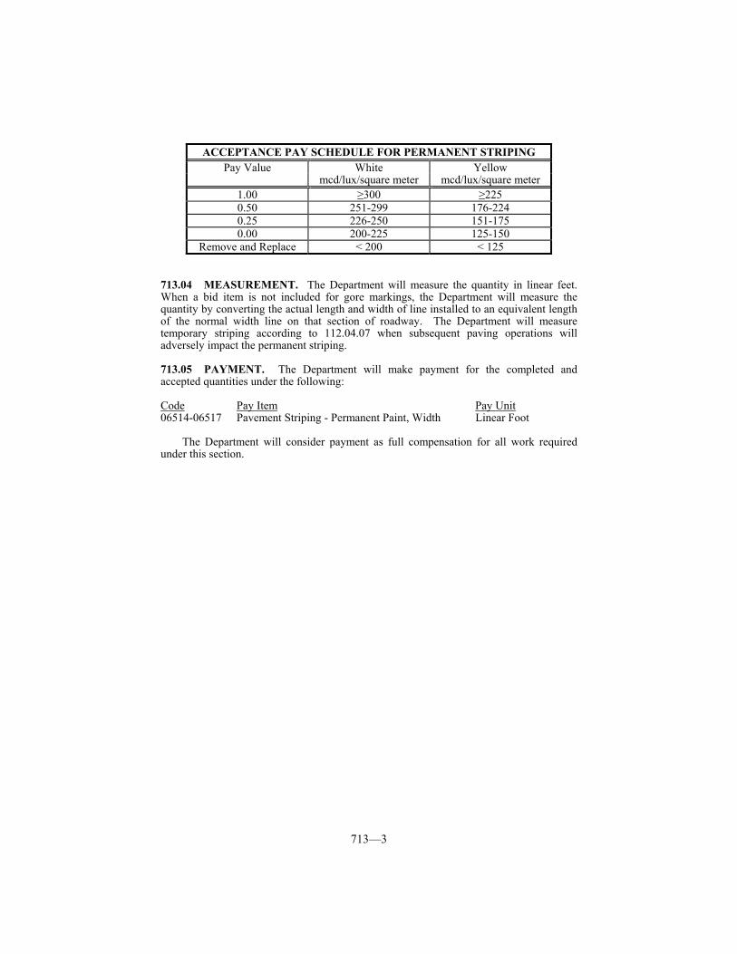
713—3
ACCEPTANCE PAY SCHEDULE FOR PERMANENT STRIPING
Pay Value White Yellow mcd/lux/square meter mcd/lux/square meter
1.00 ≥300 ≥225 0.50 251-299 176-224 0.25 226-250 151-175 0.00 200-225 125-150
Remove and Replace < 200 < 125
713.04 MEASUREMENT. The Department will measure the quantity in linear feet. When a bid item is not included for gore markings, the Department will measure the quantity by converting the actual length and width of line installed to an equivalent length of the normal width line on that section of roadway. The Department will measure temporary striping according to 112.04.07 when subsequent paving operations will adversely impact the permanent striping. 713.05 PAYMENT. The Department will make payment for the completed and accepted quantities under the following: Code Pay Item Pay Unit 06514-06517 Pavement Striping - Permanent Paint, Width Linear Foot
The Department will consider payment as full compensation for all work required under this section.
714—1
SECTION 714 ⎯ DURABLE PAVEMENT STRIPING 714.01 DESCRIPTION. Furnish and install durable marking materials, thermoplastic or Type I tape, to provide lane lines, edgelines, and gore markings as specified in the Contract. 714.02 MATERIALS AND EQUIPMENT.
714.02.01 Thermoplastic. Conform to Section 837.
714.02.02 Type I Tape. Conform to Section 836. 714.02.03 Binder. Furnish a binder that the manufacturer of the pavement marking
material recommends and the Engineer approves. Provide a binder that forms a continuous film that dries rapidly and adheres to the pavement. Provide a material that does not discolor or cause any noticeable change in the appearance of the pavement outside of the finished pavement marking. Submit the material and method of application to the Engineer and obtain written approval from the Engineer and the manufacturer of the pavement marking material before applying.
714.02.04 Drop On Glass Beads. Use beads that will ensure the pavement marking material will meet retroreflectivity requirements. The Department will evaluate the beads as part of the marking system through retroreflectivity readings.
714.02.05 Thermoplastic Application Equipment. Provide equipment with an
extrusion die that simultaneously deposits and shapes lines at a minimum thickness of 90 mils on the pavement surface. Do not use spray and ribbon gun applicators.
Ensure the application equipment conforms to the following:
1) Capable of providing continuous and uniform heat to maintain the material between 400 and 440 °F throughout the mixing, conveying, and dispensing.
2) The kettle is capable of continuous agitation during mixing and heated storage and is equipped with an automatic thermostat control device and material thermometer.
3) Motorized and capable of applying a uniform line at a rate of 3 mph. 4) Equipped with a cutoff device that provides clean, square stripe ends. 5) Equipped with an automatic bead dispenser.
714.03 CONSTRUCTION. Provide yellow centerline markings, which are defined as those separating traffic moving in opposite directions. Provide white lane line markings, which are defined as those separating traffic moving in the same direction. Ensure that these markings are skip lines and solid lines as required by Part 3 of the MUTCD. Ensure that edge lines are solid lines, and determine the color from Part 3 of the MUTCD.
Install pavement striping at the width specified in the Contract. Ensure that all lines have clean edges with a width tolerance of plus 1/2 inch. The Engineer may waive the tolerances when deviations are caused by undulation in the pavement surface.
Construct skip lines with a stripe-to-gap ratio of a 10-foot stripe to a 30-foot gap. Ensure that the length of the stripe is between 10 and 10.5 feet. Ensure that the stripe-gap cycle is between 40 and 40.5 feet.
714.03.01 Layout. Install all pavement markings according to Part 3 of the MUTCD
and the following requirements. Make the width of lane lines and edgelines as specified in the Plans or as the Engineer
directs. Make lines for gore area markings twice the normal width line for that section of roadway.
714—2
Unless striping plans are included in the proposal or otherwise directed by the Engineer, install gore area markings as shown in Figures 3B-8 and 3B-9 of the MUTCD. Do not use the optional markings shown (transverse lines in the neutral area and dotted extension of the right edgeline).
Due to the possibility that water may be retained on the roadway by the thermoplastic edgelines, place a one foot gap every 20 feet in all thermoplastic edgelines. Do not install gaps for taped edgelines.
Offset longitudinal lines at least 2 inches from longitudinal pavement construction joints. Offset longitudinal lane lines on multi-lane highways 2 inches towards the median.
On resurfacing, pavement restoration, and pavement rehabilitation projects, prepare and keep a written record of the locations of existing pavement markings, and furnish a copy to the Engineer before removing or obliterating the markings. The Engineer will notify you of any changes to the existing markings.
Before applying the pavement marking material, pre-mark the pavement surface and obtain the Engineer’s approval of the proposed location, alignment, and control guides.
714.03.02 Surface Preparation.
1) Remove existing pavement markings and clean grease, oil, mud, dust, dirt, grass,
loose gravel, or other deleterious material from the surface where pavement markings are to be applied, as directed by, and by methods acceptable to, the Engineer.
2) Remove the existing pavement markings until a minimum of 90 percent of the pavement surface is uniformly exposed throughout. Ensure that the pavement surface is in proper condition for successful bonding of the pavement markings and provides a neat appearance. Do not leave any loose or flaking existing pavement markings.
3) When removing the existing pavement markings, ensure that the finished pavement surface is not damaged or left in a condition that may mislead or misdirect the motorist. Repair any damage to the pavement, pavement joint materials, or the pavement surface caused by the removal of the existing pavement markings in a manner acceptable to the Engineer. After completing these operations, use compressed air to blow clean the pavement surface of residue and debris resulting from the removal of existing pavement markings.
4) When removal of existing pavement markings and objectionable materials obscures existing pavement markings of a lane occupied by public traffic, immediately remove the residue, including dust, from the surface being treated. Obtain the Engineer’s approval of the removal methods.
5) Place the final pavement markings on the same day that the existing pavement markings are removed.
6) On concrete surfaces and as the Engineer directs on older asphalt pavements, apply binder to the area where placing pavement marking material.
7) On new concrete pavement surfaces, remove the curing compound from the pavement surface before applying the binder and the pavement marking material.
714.03.03 Application.
A) Type I Tape. Apply according to the manufacturer’s recommendations. When
applied to concrete, cut the tape at all joints. B) Thermoplastic. Rather than installing thermoplastic pavement markings on
fresh asphalt, the Department will allow temporary striping with paint. When choosing this option, cover the temporary striping with the thermoplastic pavement markings within 30 calendar days. The Department will not require removal of the interim pavement marking paint before applying the thermoplastic pavement markings.
Install the thermoplastic material at a minimum thickness of 90 mils on the pavement surface in a melted state at a temperature from 400 and 440 °F.
714—3
Apply additional glass beads by drop-on or pressure spray methods in sufficient quantities to obtain the retroreflectivity requirements specified in Subsection 714.03.06.
Verify the adhesion of the thermoplastic to asphalt pavements by performing bond checks, at least 4 per mile of line, as follows. Approximately 60 to 120 seconds after applying a thermoplastic line to the roadway surface, cut and lift approximately a 6-inch section of thermoplastic. The thermoplastic is successfully bonding to the pavement surface if a layer of asphalt clings to the removed thermoplastic stripe and the pavement surface under the removed stripe is shiny and black.
Provide finished markings that are continuous and uniform in shape, having clear and sharp dimensions. Ensure that all lines have well-defined edges.
714.03.04 Restrictions. Do not apply the pavement marking material when air and
pavement temperatures are below 50 °F. Do not apply the pavement marking material when the surface of the pavement
contains evidence of moisture in amounts significant enough to prevent the pavement marking material from bonding to the pavement. Significant amounts of moisture can be caused by heavy dew or very humid nights as well as from rainfall.
If encountering significant amounts of moisture while applying the thermoplastic, the Contractor, at his own risk, may attempt to apply thermoplastic subject to the following restrictions. Heat the thermoplastic material to the upper temperature limit specified by the manufacturer, and apply a test line on the pavement. Perform a bond check according to Subsection 714.03.03. If the thermoplastic successfully bonds to the pavement continue to apply thermoplastic lines, provided there is evidence that the moisture is escaping through the surface of the line, as indicated by very small pin holes. If there is excessive moisture, as indicated by larger sized holes or bubbles on the surface of the line, do not apply thermoplastic until the moisture can be effectively dealt with. Perform a sufficient number of bond checks to ensure that the thermoplastic is bonding to the pavement.
714.03.05 Project Conflicts. When other construction projects are in progress within the limits of the designated work areas, install no pavement markings that will be removed or damaged by immediate subsequent construction. The Engineer will give notification of all conflicting construction projects. Schedule the installation of pavement markings after completion of the conflicting construction. When scheduling is impossible or creates an undue hardship, the Engineer will delete the intersection from this project.
714.03.06 Proving Period for Durable Markings. A 180 day proving period will
follow the application of the durable markings. During this period, the Engineer will make such observations as are necessary to determine if the markings are acceptable. The proving period begins when the facility is opened to traffic.
A) Requirements.
1) Type I Tape. During the proving period, ensure that the pavement marking material shows no signs of failure due to blistering, excessive cracking, bleeding, staining, discoloration, oil content of the pavement materials, deterioration due to contact with grease deposits, oil, diesel fuel, or gasoline drippings, chipping, spalling, poor adhesion to the pavement, loss of retroreflectivity, vehicular damage, and normal wear. Type I Tape is manufactured off site and warranted by the manufacturer to meet certain retroreflective requirements. As long as the material is adequately bonded to the surface and shows no sign of failure due to the other items listed in Subsection 714.03.06 A) 1), retroreflectivity readings will not be required. In the absence of readings, the Department will accept tape based on a nighttime visual observation.
714—4
2) Thermoplastic. During the proving period, ensure that the thermoplastic pavement marking material shows no signs of failure due to blistering, excessive cracking, bleeding, staining, discoloration, oil content of the pavement materials, smearing or spreading under heat, deterioration due to contact with grease deposits, oil, diesel fuel, or gasoline drippings, chipping, spalling, poor adhesion to the pavement materials, loss of retroreflectivity, vehicular damage and normal wear.
The minimum retroreflectivity requirements at the end of the proving period, as measured with a Department approved 30 meter geometry handheld or mobile retroreflectometer, are as follows:
White: 300 mcd/lux/square meter Yellow: 225 mcd/lux/square meter
The Department will take these measurements between 150 and 210 days after the start of the proving period, with acceptance based on KM 202 or KM 203 as applicable. If the Department determines that the markings are acceptable, the installation of the markings will be considered complete.
B) Failure. During the proving period, the Department will consider markings
defective when the retroreflectivity falls below the minimum required or the material fails to meet the other requirements of A) above. Additionally, when more than 10 percent of any one-mile section or individual gore area is defective, the Department will consider the entire section defective. The Department will consider each edge line, centerline, lane line and gore area marking separately.
C) Corrective Work. If a line is found to be defective, repair or remove and replace the line. Perform pavement marking replacement according to the requirements specified in this subsection for the initial application. The corrective work will be subject to a proving period as listed above.
714.03.07 Marking Removal. Remove all markings made in error or not
conforming to the traffic operation in use. Remove markings by either an abrasion or water blasting process to the satisfaction of the Engineer. When water blasting, vacuum all marking material and removal debris concurrently with the blasting operation. Do not paint with asphalt binder or other material to obliterate the markings.
714.03.08 Acceptance of Non-Specification Thermoplastic Markings. When reasonably acceptable work has been produced but retroreflectivity requirements are not met, the Department may accept the work according to Subsection 105.04. When the Engineer determines that the markings may be left in place, the Department will accept them at a reduction in the Contract unit bid price according to Acceptance Pay Schedule for Thermoplastic. 714.04 MEASUREMENT. When a bid item is not included for gore markings, the Department will measure the quantity by converting the actual length and width of line installed to an equivalent length of the normal width line on that section of roadway.
714.04.01 Thermoplastic Pavement Markings. The Department will measure for payment by the units listed in the Quantity Summary. The Department will not measure sampling, testing, surface preparation, pre-marking, interim marking, and binder application for payment and will consider them incidental to the thermoplastic bid items. The Department will not measure corrective work for payment.
714.04.02 Durable Pavement Markings, Type I. The Department will measure for
payment by the units listed in the Quantity Summary. The Department will not measure sampling, testing, surface preparation, pre-marking, and binder application for payment
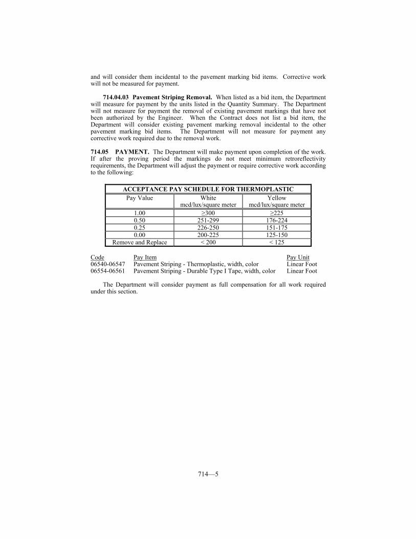
714—5
and will consider them incidental to the pavement marking bid items. Corrective work will not be measured for payment.
714.04.03 Pavement Striping Removal. When listed as a bid item, the Department will measure for payment by the units listed in the Quantity Summary. The Department will not measure for payment the removal of existing pavement markings that have not been authorized by the Engineer. When the Contract does not list a bid item, the Department will consider existing pavement marking removal incidental to the other pavement marking bid items. The Department will not measure for payment any corrective work required due to the removal work. 714.05 PAYMENT. The Department will make payment upon completion of the work. If after the proving period the markings do not meet minimum retroreflectivity requirements, the Department will adjust the payment or require corrective work according to the following:
Code Pay Item Pay Unit 06540-06547 Pavement Striping - Thermoplastic, width, color Linear Foot 06554-06561 Pavement Striping - Durable Type I Tape, width, color Linear Foot
The Department will consider payment as full compensation for all work required under this section.
ACCEPTANCE PAY SCHEDULE FOR THERMOPLASTIC Pay Value White Yellow
mcd/lux/square meter mcd/lux/square meter 1.00 ≥300 ≥225 0.50 251-299 176-224 0.25 226-250 151-175 0.00 200-225 125-150
Remove and Replace < 200 < 125
715—1
SECTION 715 ⎯ PANEL TRAFFIC SIGNS 715.01 DESCRIPTION. Furnish and install extruded panel traffic signs. Traffic signs include ground mounted, overhead structure mounted, or bridge mounted signs. 715.02 MATERIALS.
715.02.01 Panel Signs. Conform to Section 833.
715.02.02 Concrete. Conform to Subsection 601.02 and 601.03.
715.02.03 Steel Reinforcement. Conform to Section 602.
715.02.04 Structural Steel. Conform to Section 812.
715.02.05 Miscellaneous Metals. Conform to Section 813.
715.02.06 Retroreflective Materials. Conform to Section 830.
715.02.07 “Pop” Fasteners. Use corrosion resistant protruding head “pop” rivets with a minimum diameter of 1/8 inch. Obtain the Engineer’s approval before use. 715.03 CONSTRUCTION. The Department may inspect fabrication and erection work. The Department will perform a day and night inspection after the installation is complete.
If a manufacturer provides a warranty on any materials covered under these specifications, furnish the same warranty to the State. Perform the work according to the requirements specified in the following publications: • MUTCD • AASHTO Specifications for Design and Construction of Structural Supports for
Highway Signs • Federal Standard 595, Standard Highway Sign Colors • Standard Highway Signs
Use Class A concrete according to Subsection 601.03. 715.03.01 Location. Use the Plans as general guidance for the extent and general
arrangement of signs. Consider sign locations specified in the Plans as approximate only. Determine the exact location for each sign and obtain the Engineer’s approval. When it is necessary to relocate any sign more than 25 feet from the station listed, obtain the Division of Traffic’s approval. Center overhead signs over the lane or lanes to which they apply. Allow for differences in elevation across the full shoulder width, as specified in the Plans, in maintaining the required 18-foot minimum vertical clearance to the bottom of the lowest parts of the signs or supports for overhead signs. Submit all proposed revisions in writing to the Engineer for written approval.
715.03.02 Messages. Sign messages specified in the Plans are the final messages. Due to construction phasing, the Engineer may make changes in some messages. If the Engineer changes a message before the sign installation store the final message copy on the project. Conform message spacing to the applicable requirements of the previously cited publications for guide signs, and the manufacturer’s recommendations for sign sizes indicated, as the Engineer approves. Center message copy over the lane or lanes to which they apply.
715.03.03 Attachment. Attach letters, symbols, numbers, and borders to sign faces with “pop” fasteners (“pop” rivets).
715—2
715.03.04 Shields. For panel sign mounted route markers, use a retroreflectorized
white cut-out for the US shield and KY round shape, omitting the black background of the standard rectangular shapes. Do not use borders on the cut-out shapes. Use the dimensions shown in the Standard Highway Signs Manual. Space route markers evenly across the panel sign face. Provide Route Markers for panel signs that meet the specification requirements for Type VII, VIII or IX Class I of ASTM D 4956, and that consist of reflective sheeting having an integral air cavity between the front surface and the optical elements, mounted on fully covering aluminum base copy stock not otherwise embossed or crimped, but having a minimum thickness of 0.080 inches.
715.03.05 Covering. Cover sign faces only when absolutely necessary and keep covered only as long as necessary. Do not use tape, paper, plastic, or sheet metal covers. Replace any signs damaged as a result of being covered at no expense to the Department.
715.03.06 Shop Drawings. Submit 5 complete sets of detailed shop drawings to the Engineer for written approval before fabricating signs. Before installation, obtain the Engineer’s written approval of drawings, descriptions, manufacturer’s cuts, etc. covering all materials to be used. Submit mill test reports for I-beams, wide flange beams, aluminum or steel panels, and each different gauge of aluminum or steel sheeting used to the Engineer for approval before installation.
715.03.07 Fabrication. Hot dip galvanize all steel components after completing fabrication. Regalvanize or paint all abraded or damaged surfaces with 2 coats of commercially available zinc rich paint.
Ensure that sign structures are free from kinks, twists, or bends and are uniform in appearance. Assemble completed sections in the shop and check them for straightness, alignment, and dimensions. Correct any irregularities.
Consider sign post lengths as approximate only. Conform to the applicable requirements contained in AWS for welded fabrication.
715.03.08 Footings, Bases, and Pedestals. Provide protection for traffic during construction of concrete bases for overhead sign structures.
Exercise caution during any excavation to prevent damaging existing utilities whether specified or not specified in the Plans. Repair or replace any utilities that are disturbed or damaged during construction at no additional expense to the Department. Provide the Engineer the opportunity to inspect repairs to damaged utilities before covering the repairs.
Construct footings and bases according to Subsection 601.03. The Department will allow construction of footings against undisturbed earth without forms, unless otherwise directed. Slope top surfaces of bases and pedestals to provide for drainage. Provide an ordinary surface finish for all exposed concrete. Construct a rustication groove in all pedestals. Cure concrete according to Subsection 601.03.17.
Remove beam sign supports concurrently with the relocation of affected signs to new supports. Grade, to the existing slope, any areas disturbed by removing existing signs or constructing new signs, and reseed as the Engineer directs.
715.03.09 Sign Beams and Supports. Use beams of sufficient length to extend from the top of the sign to the required base embedment. Use either Type A (standard fixed beam installation) or Type B (uni-directional break-away beam installation) or Type C (omni-directional break-a-way beam installation) as specified in the Plans. Embed Type "A" and Type "B" beams in concrete to a depth equal to the dimension "a" as indicated for each sign. Provide a concrete footing for Type "C" beams according to the design on the Type "C" beam sheets.
Wait 7 calendar days after placing concrete before mounting beams and supports to the bases or pedestals. Where aluminum is in contact with concrete, thoroughly coat the contacting surface with alumilastic compound or an approved equal in order to completely
715—3
insulate the aluminum from the concrete. Where bond between the aluminum and concrete is desired, coat the aluminum with commercially available zinc chromate paint, and allow it to dry before installation.
A) Type A Beam. Furnish A 36 steel beams galvanized according to ASTM A 123. B) Type B Beam. Specifications for Type B uni-directional break-a-way beams are
listed on the detail sheet for Type “B” beams. Specifications for Type B beams are listed on the break-away detail sheet.
C) Type C Beam. Specifications for Type C omni-directional break-a-way beams are listed on the details sheets for Type “C” beams.
715.03.10 Bridge Mounting for Signs. Do not install brackets for support of bridge
mounted signs within 6 inches of open joints in concrete handrail plinths. The Department will allow moving of supports to clear handrail posts. Place sign brackets on 4-foot maximum centers with a 2-foot maximum sign overhang.
When necessary, remove existing handrails to drill anchor bolt holes. Reinstall handrails after drilling. Locate bolt holes drilled in prestressed concrete beams to not interfere with steel strands. Drill holes for concrete beams with a rotary type core drill. Do not use impact type drills. Install bolts with expansion plugs and lock washers in the holes and fill the void between the plug and face of the concrete with non-shrinking grout.
715.03.11 Mounting Signs. Install new concrete bases, support beams, etc. before dismantling any existing sign. When existing signs are to be out of service for more than one work shift, install temporary signing of the proper color, shape, and with copy of similar configuration to existing signs at the same approximate station as the out of service sign. Install sign panels on sign structures, beams, or bridge mounted brackets as specified in the Plans. Delay installation as long as possible to avoid any damage to the sign. Replace all damaged signs. 715.04 MEASUREMENT.
715.04.01 Concrete. The Department will measure according to Subsection 601.04.
715.04.02 Steel Reinforcement. The Department will measure according to Subsection 602.04.
715.04.03 Sign Supports. The Department will measure the quantity by each individual unit.
The Department will not measure clearing and grubbing, excavation, electrical conduit and ground rods located in support bases, and temporary panel signing for payment and will consider them incidental to this item of work.
715.04.04 Beams. The Department will measure the quantity in pounds.
715.04.05 Bridge Mounted Sign Fixtures. The Department will measure the quantity by each individual unit. A unit is as all material necessary for mounting a bridge mounted sign of given size.
715.04.06 Sign Panels. The Department will measure the quantity in square feet for each size and type. 715.05 PAYMENT. The Department will make payment for the completed and accepted quantities under the following: Code Pay Item Pay Unit 06490 Class A Concrete for Signs See Subsection 601.05
715—4
06491 Steel Reinforcement for Signs See Subsection 602.05 06416-06426, 06436, Sign Supports, Size and Type Each 06438, 06443, 06445 06400, 06440, 06441 GMSS Galvanized Steel, Type Pound 06402 GMSS Aluminum Pound 06448 Sign Bridge Attachment Bracket Each 06405-06409 Sign Panels, Type and Size Square Foot
The Department will consider payment as full compensation for all work required under this section.
716—1
SECTION 716 ⎯ ROADWAY LIGHTING SYSTEMS 716.01 DESCRIPTION. Furnish, install, and connect roadway lighting systems, with accessories according to the Contract. 716.02 MATERIALS.
716.02.01 Roadway Lighting Materials. Conform to Section 834. Obtain the Engineer’s approval for all materials before installation. Submit for material approval 7 copies of descriptive literature, drawings, and any requested design data. Do not make substitutions for approved materials without written permission as described above.
716.02.02 Paint. Conform to Sections 821 and 834.
716.02.03 Concrete. Conform to Subsection 601.02 and 601.03. 716.03 CONSTRUCTION. Perform the work according to: 1) the Contract, 2) National Electrical Code, 3) AASHTO Standard Specifications for Structural Supports for Highway Signs,
Luminaires and Traffic Signals, 2001 edition, 4) AASHTO Roadside Design Guide, 5) AASHTO Roadway Lighting Design Guide, 2005 edition, 6) Manual on Uniform Traffic Control Devices for Streets and Highways, and 7) the standards of the utility company servicing the installation.
Before ordering materials, confirm the type and location of the service available from the utility company.
After completing the installation and before the electrical service is connected, obtain a certificate of compliance from the Kentucky Department of Housing, Buildings and Construction, Electrical Inspection Division.
Coordinate with the Kentucky Department of Housing, Buildings and Construction, Electrical Inspection Division, to ensure the cabinet and all components within are approved as an assembly.
The Plans indicate the extent and general arrangement of the lighting circuits and equipment and are for general guidance. Advise the Engineer in writing and obtain written approval for any necessary modifications.
Stake pole locations and obtain the Engineer’s approval. Use Class A concrete according to Subsection 601.03.
716.03.01 Wiring. Where installing more than one circuit within the same conduit, affix permanent circuit identification numbers to the wires wherever the wiring emerges, including junction boxes, transformer bases, and control cabinets.
716.03.02 Conduit Installation. Provide rigid steel conduit encasement for all conductors except as specified in the Plans. The Department will allow bonded slip joints for joining rigid conduit to junction boxes. When a standard coupling cannot be used, use an approved threaded union coupling. Ream all conduit ends to remove burrs and sharp edges. Paint damaged portions of galvanized surfaces and untreated threads resulting from field cuts with an Engineer approved rust prohibitive paint. Ensure that conduit bends have a radius of not less than 12 times the nominal diameter of the conduit.
Lay conduit not subjected to traffic to a depth of no less than 18 inches. Lay ducted cables to a depth of 2 feet. On transverse crossings under roadway surfaces and shoulders, place the conduit at a depth of no less than 2 feet below grade. Likewise, run ducted cables inside rigid steel conduits, or other Engineer approved methods, when crossing roadways. Make all pavement crossings by placing conduit in the subgrade before paving
716—2
or by boring and jacking under existing pavements. When it is necessary to bore under roadways and ramps, obtain the Engineer’s approval of the boring procedure. Do not cut any pavement without obtaining the Engineer’s prior approval. Before starting backfilling, allow the Engineer to inspect the conduit installation. Place and compact the backfill materials in lifts of 9 inches or less. Restore all disturbed areas as a result of the Contractor’s operations to the Engineer’s satisfaction. Bond together conduits, junction boxes, metal poles, and control boxes throughout the lighting system to all ground rods by using grounding bushings on the conduit ends. Bond these conduits to the electrical system ground.
Install underground utility warning tape immediately above the circuit cables. Bury the tape at a depth of 6 to 10 inches. Use a durable and colorfast tape conforming with the APWA-ULCC National Color Code with black lettering on red that continuously reads “CAUTION: ELECTRIC LINE BURIED BELOW” alternating with a no digging symbol.
716.03.03 Splicing. When the Engineer allows splicing, splice only in junction boxes, in transformer bases, or in pole bases when no transformer base is provided. Make butt splices, soldered and encased in waterproof resin filled splicing kits. Use copper of the correct wire range, 3M Scotchcast splicing kits or approved equal, and Scotchcast #4 resin or approved equal. Encase each conductor, including the ground, in a separate splice kit. Make splices for connecting leads from multiple circuit conductors to ballast terminals with approved field applied connector kits. Where specifically allowed by the plans, ensure the splices are of the correct size for the wire being used.
716.03.04 Painting. Clean ungalvanized or damaged surfaces of exposed junction boxes, pull boxes, control panels, poles, and similar equipment, and apply one coat of an inhibiting paint and two coats of aluminum paint, inside and out, after completing installation. For items fabricated from galvanized or nonferrous alloys, which are inherently rust resistant, paint only on damaged surfaces with an application of inorganic zinc rich primer or aluminum paint, as applicable.
716.03.05 Lighting Standard Installation. Ensure that concrete bases for lighting standards, up to 50 feet high, have a minimum depth of 6 1/2 feet and a minimum diameter of 2 feet. Construct a level base, with no more than a 3/8-inch gap existing between the concrete base and the transformer base when the pole is plumbed. The Department will allow steel plates or washers between the nuts and the transformer base or pole for stabilization and shims to plumb the pole for gaps up to 1/4 inch.
For breakaway supports, conform to Section 7 of the Standard Specifications for Structural Supports for Highway Signs, Luminaires, and Traffic Signals. Grade the surrounding surface appropriately to meet the 4-inch breakaway support stub height.
716.03.06 Marker Installation. When specified in the Plans, mark the position of buried circuits with concrete slab markers. Install cable markers immediately above the cable. Place the markers with the top exposed approximately one inch above ground. Mark each cable run at approximately 100-yard increments between junction boxes and/or light poles, with additional markers at each change of direction. Install concrete slab markers at the end of the conduits crossing a roadway if a junction box is not present.
716.03.07 Drawings. Before final inspection of the roadway lighting system, provide a complete set of reproducible as-built drawings that show the arrangement and locations of all equipment and circuits. Include each duct or conduit pavement crossing with distances to permanent markers, such as structures and curb lines. Keep a daily record of all conduit placed in trenches, showing the distance from the pavement edge, the depth, and the length of runs, and indicate these on the as-built drawings.
716.03.08 Testing. After completing the service and equipment installations, conduct an operating test. Demonstrate that the system operates according to the Contract.
716—3
Ensure that circuits test free of shorts and unauthorized grounds and have an insulating resistance of no less than 100 megohms when tested with 500 volt direct current potential in a reasonably dry atmosphere between conductors and ground. The Department will also conduct its own tests with its own equipment before final acceptance. 716.04 MEASUREMENT.
716.04.01 Roadway Lighting Systems. The Department will measure the work in the units specified in the Contract.
The Department will consider any costs associated with securing service, required certificates, approval as an assembly, and providing as-built drawings incidental to this item of work.
716.04.02 Trenching and Backfilling. The Department will measure the quantity in linear feet. 716.05 PAYMENT. The Department will make payment for the completed and accepted quantities under the following: Code Pay Item Pay Unit ---- Roadway Lighting, Contract Items Contract Units 04820 Trenching and Backfilling Linear Foot
The Department will consider payment as full compensation for installing and placing the complete roadway lighting systems in satisfactory operation.
717—1
SECTION 717 ⎯ THERMOPLASTIC INTERSECTION MARKINGS
717.01 DESCRIPTION. Furnish and install thermoplastic intersection markings (Stop Bars, Crosswalks, Turn Arrows, etc.) by either a machine applied, screed extrusion process or by applying preformed thermoplastic intersection marking material. 717.02 MATERIALS AND EQUIPMENT.
717.02.01 Preformed Thermoplastic Intersection Marking Material. Select from the Department’s List of Approved Materials.
717.02.02 Extruded Thermoplastic Pavement Marking Material. Conform to
Section 837.
717.02.03 Binder. Conform to Subsection 714.02.03 717.02.04 Drop On Glass Beads. Use beads that will ensure the pavement marking
material will meet retroreflectivity requirements. The Department will evaluate the beads as part of the marking system through retroreflectivity readings.
717.02.05 Extruded Thermoplastic Application Equipment. Provide equipment
with a shaping die that simultaneously deposits and shapes lines at a minimum thickness of 90 mils on the pavement surface. Do not use spray and ribbon gun applicators.
Ensure the application equipment conforms to the following:
1) Capable of providing continuous and uniform heat to maintain the material between 400 and 440 °F throughout the mixing, conveying, and dispensing.
2) The kettle is capable of continuous agitation during mixing and heated storage and is equipped with an automatic thermostat control device and material thermometer.
3) Equipped with a cutoff device that provides clean, square stripe ends. 4) Equipped with an automatic bead dispenser.
717.03 CONSTRUCTION.
717.03.01 Layout. On resurfacing, pavement restoration, and pavement rehabilitation projects, prepare and keep a written record of the locations of existing pavement markings, and furnish a copy to the Engineer before removing or obliterating the markings. The Engineer will notify you of any changes to the existing markings.
On new construction, the Department will provide more detailed information for each intersection prior to beginning work. This information will consist of plans, a drawing of each intersection, or an inspector to work with each crew to layout the markings in the field.
Before applying the pavement marking material, pre-mark the pavement surface and obtain the Engineer’s approval of the proposed location, alignment, and control guides.
717.03.02 Surface Preparation. Clean all grease, oil, mud, dust, dirt, grass, loose
gravel, or other deleterious material from the surface where pavement markings are to be applied as directed by, and by methods acceptable to, the Engineer.
On concrete surfaces and as the Engineer directs on older asphalt pavements, apply binder to the area where placing pavement marking material. Ensure that all solvents have evaporated from the binder before applying the marking material. On new concrete pavement surfaces, remove the curing compound from the pavement surface before applying the binder and the pavement marking material.
717—2
717.03.03 Application. Install extruded thermoplastic at a minimum thickness of 90 mils on the pavement surface in a melted state at a temperature from 400 and 440 °F. Install preformed thermoplastic according to manufacturer's instructions at a minimum thickness of 125 mils. Apply additional glass beads by a drop-on method at a rate that satisfies the retroreflectivity requirements of Subsection 717.03.05.
When installing symbols and legends (turn arrows, the word “ONLY” etc.) by the extrusion process, ensure that the finished markings conform to the standard size and shape in the Manual on Uniform Traffic Control Devices.
Verify the adhesion of the thermoplastic to asphalt pavements by performing bond checks as follows. Approximately 60 to 120 seconds after applying the thermoplastic material cut and lift approximately a 6-inch section. The thermoplastic is successfully bonding to the pavement surface if a layer of asphalt clings to the removed thermoplastic and the pavement surface under the removed section is shiny and black.
Ensure that finished markings are continuous and uniform in shape having clear and sharp edges with uniform bead distribution across the entire width and length of the line, symbol, or legend.
717.03.04 Restrictions. Do not apply the pavement marking material when air and
pavement temperatures are below 50 °F. Do not apply the pavement marking material when the surface of the pavement
contains evidence of moisture in amounts significant enough to prevent the pavement marking material from bonding to the pavement. Significant amounts of moisture can be caused by heavy dew or very humid nights as well as from rainfall.
If encountering significant amounts of moisture while applying the thermoplastic, the Contractor, at his own risk, may attempt to apply the thermoplastic material subject to the following restrictions. Heat the thermoplastic material to the upper temperature limit specified by the manufacturer, and apply a test line on the pavement. Perform a bond check according to Subsection 717.03.03. If the thermoplastic successfully bonds to the pavement continue to apply thermoplastic material, provided there is evidence that the moisture is escaping through the surface of the material, as indicated by very small pinholes. If there is excessive moisture, as indicated by larger sized holes or bubbles on the surface of the material, do not apply thermoplastic until the moisture can be effectively dealt with. Perform a sufficient number of bond checks to ensure that the thermoplastic is bonding to the pavement.
717.03.05 Proving Period. A proving period of 180 days will follow the application
of the durable markings. During this period, the Engineer will make such observations as are necessary to determine if the markings are acceptable. The proving period begins when the facility is opened to traffic.
A) Requirements. During the proving period, ensure that the material shows no signs of failure due to blistering, excessive cracking, bleeding, staining, discoloration, oil content of the pavement materials, smearing or spreading under heat, deterioration due to contact with grease deposits, oil, diesel fuel, or gasoline drippings, chipping, spalling, poor adhesion to the pavement materials, loss of retroreflectivity, vehicular damage and normal wear.
The minimum retroreflectivity requirements at the end of the proving period, as measured with a Department approved 30 meter geometry handheld retroreflectometer, are as follows:
White: 300 mcd/lux/square meter Yellow: 225 mcd/lux/square meter
The Department will take these measurements between 15 and 45 days after
the start of the proving period, with acceptance based on KM 201. If the Department determines that the markings are acceptable, the installation of the markings will be considered complete.
717—3
B) Failure. The Department will consider any marking defective when the readings for that marking do not satisfy the retroreflectivity requirements or more than 10 percent of the material fails to meet the other requirements of A) above. The Department will consider each marking separately.
C) Corrective Work. If any marking is found to be defective, repair or remove and replace the marking. Perform pavement marking replacement according to the requirements specified in this subsection for the initial application. The corrective work will be subject to a proving period as listed above.
717.03.06 Marking Removal. Remove all markings made in error or not
conforming to the traffic operation in use. Remove markings by either an abrasion or water blasting process to the satisfaction of the Engineer. When water blasting, vacuum all marking material and removal debris concurrently with the blasting operation. Do not paint with asphalt binder or other material to obliterate the markings.
717.03.07 Acceptance of Non-Specification Markings. When reasonably acceptable work has been produced but retroreflectivity requirements are not met, the Department may accept the work according to Subsection 105.04. When the Engineer determines that the markings may be left in place, the Department will accept them at a reduction in the Contract unit bid price according to Acceptance Pay Schedule for Thermoplastic. The Department will not consider these procedures a means to continue accepting non-specification markings. 717.04 MEASUREMENT. The Department will measure the intersection markings on a per unit basis for items listed in the Quantity Summary.
The Department will not measure the removal of existing markings, layout, surface preparation, binder, glass beads, or testing for payment and will consider them incidental to the installation of the new marking. The Department will exclude the gaps when measuring dotted lane line extensions. 717.05 PAYMENT. The Department will make payment for the completed and accepted quantities under the following:
ACCEPTANCE PAY SCHEDULE FOR THERMOPLASTIC Pay Value White Yellow
mcd/lux/square meter mcd/lux/square meter 1.00 ≥300 ≥225 0.50 251-299 176-224 0.25 226-250 151-175 0.00 200-225 125-150
Remove and Replace < 200 < 125 Code Pay Item Pay Unit 06565, 06566 Pavement Marking, Thermoplastic X-Walk, Size Linear Foot 06567, 06568 Pavement Marking, Thermoplastic Stop Bar, Size Linear Foot 06569 Pavement Marking, Thermoplastic Cross Hatch Square Foot 06572 Pavement Marking, Dotted Lane Extension Linear Foot 06573-06575, 06578 Pavement Marking, Thermoplastic Arrow, Type Each 06576 Pavement Marking, Thermoplastic “ONLY” Each 06577 Pavement Marking, Thermoplastic “SCHOOL” Each
The Department will consider payment as full compensation for all work required under this section.
718—1
SECTION 718 ⎯ BRIDGE END OBJECT MARKERS 718.01 DESCRIPTION. Furnishing and place Type 2 Object Markers at bridge ends. See Section 3C.01 of the MUTCD for a general description. 718.02 MATERIAL. The Type 2 Object Marker has a vertical dimension of one foot and a horizontal dimension of 6 inches, and consists of reflective materials on an aluminum sheet.
718.02.01 Retroreflective Sheeting. Provide yellow sheeting conforming to Section 830.
718.02.02 Aluminum Substrate. Conform to Section 833.
718.03 CONSTRUCTION. Prepare the aluminum sheeting and the reflective material applied according to the manufacturer's recommendations.
Mount the object marker on a post meeting the requirements for Type II in Section 832. The minimum length of post is 8 feet. The Contractor is responsible for determining the actual length necessary at each location.
Install the object markers as near each bridge end as practical. Ensure the inside edge of the marker is in line with the inner edge of the bridge wall. Drive the post 3 feet, with one foot behind the marker and the remaining length as necessary to provide a mounting height to the bottom of the marker of 4 feet above the surface of the nearest traffic lane. 718.04 MEASUREMENT. The Department will measure the quantity of Object Marker Type 2 by each individual unit. The Department considers a unit to include all materials, including the post, necessary to acceptably furnish and install the marker. 718.05 PAYMENT. The Department will make payment for the completed and accepted quantities under the following: Code Pay Item Pay Unit 02565 Object Marker, Type 2 Each
The Department will consider payment as full compensation for all work required under this section.
719—1
SECTION 719 ⎯ GUARDRAIL 719.01 DESCRIPTION. Furnish and install or remove all necessary material for each type of guardrail, end treatment, terminal section, and guardrail bridge end connector. Remove and relocate, or remove and reset, all necessary material for each type of guardrail. Adjust guardrail, including replacement of existing offset blocks, with new modified offset blocks. Furnish additional new hardware as needed to complete the adjustment. 719.02 MATERIALS.
719.02.01 Guardrail Systems. Conform to Section 814.
719.02.02 Concrete. Use Class A concrete conforming to Subsection 601.02 and 601.03.
719.02.03 Reinforcement Steel. Conform to Section 811. 719.02.04 Grout. Conform to Subsection 601.02.
When used in placement on a curve having a radius of 150 feet or less, curve
guardrail in shop. Mark the radius of curvature on each of the curved elements. Furnish rail elements that have a nominal length of 13 1/2 feet.
Use the same type of posts, fastenings, and accessories throughout the project. 719.03 CONSTRUCTION. Do not leave uncompleted guardrail, bridge end connectors, terminal sections, or end treatments exposed to the traveling public. Construct guardrail, end treatments, bridge end connectors, and terminal sections behind lane closures or shoulder closures.
Construct guardrail 27 inches, with a tolerance of plus or minus one inch, above the true theoretical pavement elevations. Compute these elevations from the proposed pavement edge elevations or from other methods to ensure construction of the guardrail to the true gradient and with no sags.
Paint all damaged galvanizing with 2 coats of zinc dust-zinc oxide paint conforming to Federal Specification TT-P-641.
Provide permanent or temporary guardrail where it presently exists throughout the winter close-down periods of the Contract as the Engineer directs.
719.03.01 Setting Posts. Install posts according to the Contract without damaging the road or shoulder. Provide extra length posts when the Engineer directs to do so. Do not damage any portion of the driven posts. If damage occurs, discontinue driving and set remainder of the posts in excavated holes. Remove damaged portions of posts after installation.
Ram bottoms of dug post holes to provide a stable foundation. When encountering rock or rock fill, drill and grout posts in holes 2 feet in depth and slightly larger than the post sections. Proportion grout according to Subsection 601.03. Set posts vertically with the rail faces in a straight line, or when on a curve, at a uniform distance from the pavement. Backfill post holes in layers not to exceed 6 inches, and compact until the post is solid, firm, and in true alignment. Cut and set timber post tops to correct grade, and bevel according to the Standard Drawings. Bore holes at proper places to attach the rails. Anchor posts according to the Standard Drawings. Repair all damaged pavement.
Do not drive guardrail posts within one foot of the outlet pipe for pavement edgedrains. Repair all damage to the outlet pipe for pavement edgedrains caused by guardrail installations. If repair is not possible, remove and replace damaged outlet pipe.
719.03.02 Placing Rail. Construct the guardrail to the alignment and at the locations shown in the Contract. Splice rail element by lapping in the direction of traffic. Bolt rail
719—2
element to each post through the holes provided in the rail. Where the holes are slotted for expansion, erect rail with the bolt in the center of the slot. Install nuts on the backside of all bolts, either through splices or through rail and posts. Draw bolts tightly. Extend the bolt at least 1/4 inch beyond the nut. Do not tighten bolts so tightly through expansion members that they prevent functioning of the members.
Erect rail so it appears smooth, uniform, continuous, and closely parallels the line and grade of the pavement.
Provide the type of end treatments, terminal sections, and guardrail bridge end connectors specified in the Contract. The Department will not allow field cutting, punching, burning, or welding.
719.03.03 Remove Rail. Remove the existing guardrail system, which includes bridge end connectors, terminal sections, or guardrail end treatments including all associated concrete, components, and incidentals. Fill all voids left from pulling guardrail posts with dry sand. Do not damage guardrail.
719.03.04 Relocate the Existing Guardrail System. Relocate the existing rail and posts to the alignment and at the locations shown in the Contract. Spot paint edges of all holes punched in the existing rail and posts that are to be reused. Spot paint all scratches or marred areas in completed installations where the galvanizing has been damaged. Spot paint with 2 coats of zinc dust-zinc oxide paint conforming to Federal Specification TT-P-641.
Do not intermix new pieces of guardrail with pieces of existing rail at any installation. Add new pieces, as needed, on one or both ends of an installation.
The Department will retain ownership of all items in the existing system not suitable for reconstruction, except concrete. Remove and dispose of existing concrete off the right-of-way.
If additional guardrail is needed to replace damaged guardrail, furnish and install new guardrail.
719.03.05 Adjust Existing Guardrail. Adjust existing guardrail to the alignment and at the locations shown in the Contract. Remove existing rail elements and offset blocks from the existing posts. Install new modified offset blocks. Reinstall rail elements. Realign guardrail both vertically and horizontally at the raised elevation.
When new end treatments, terminal sections, or bridge connectors are not specified, connect adjusted rail to the existing installation in a smooth transition. When new end treatments, terminal sections, or bridge connectors are specified, construct at new shoulder elevation or new grade condition.
719.03.06 Temporary Guardrail. Conform to the same construction requirements for temporary guardrail as for permanent guardrail. The Department will show temporary guardrail locations in the Contract. Maintain the temporary guardrail system for the duration of its use. Retain ownership of damaged or surplus components. The Contractor may use undamaged components in permanent installations.
719.03.07 Salvaged Material. The Department will retain ownership of the existing guardrail, guardrail post, and hardware. Stack W-beam rail 45 per bundle (3 wide, 15 high, overlapped). Stack and band metal posts 50 per bundle (5 wide, 10 high, overlapped). Bag nuts, bolts, and washers. Salvage a minimum of 80 percent of the nuts, bolts, and washers. Deliver existing guardrail and components to the Maintenance Bailey bridge lot located on Wilkinson Blvd in Frankfort, KY. Contact the lot supervisor at (502) 564-2946 to schedule delivery of material a minimum of 10 working days in advance of delivery. Deliver the material between the hours of 8:00AM and 3:30PM EST, Monday through Friday. Dispose of all removed concrete off the right-of-way.
719—3
719.04 MEASUREMENT.
719.04.01 Guardrail. The Department will measure the quantity in linear feet along the actual length of the rail between the limits for end treatments, terminal sections and bridge end connections, and crash cushions. The Department will measure the quantity of shop curved guardrail in linear feet at 1.3 times the actual length.
719.04.02 Guardrail Terminal Sections. The Department will measure the quantity by each individual unit.
719.04.03 Extra Length Post. The Department will measure the quantity by each individual unit. The Department will still measure guardrail at locations where extra length post are required as this item represents only the added work and material required by the extra length.
719.04.04 Guardrail End Treatment. The Department will measure the quantity by each individual unit that is not a part of the guardrail.
719.04.05 Crash Cushion. The Department will measure the quantity by each individual unit that is not a part of the guardrail.
719.04.06 Guardrail Bridge End Connector. The Department will measure the quantity by each individual unit, including their end treatment.
719.04.07 Guardrail Connector to Concrete Median Barrier. The Department will measure the quantity, by each individual unit, according to Standard Drawing RBC-100.
719.04.08 Remove Guardrail. The Department will measure the quantity in linear feet. The Department will not measure the delivery and stacking of guardrail, posts, and its hardware for payment and will consider it incidental to this item of work.
719.04.09 Relocate Guardrail System. The Department will measure the quantity in linear feet.
719.04.10 Adjust Guardrail. The Department will measure the quantity in linear feet.
719.04.11 Temporary Guardrail. The Department will measure the quantity in linear feet. The Department will not measure maintenance and removal for payment and will consider it incidental to this item of work. 719.05 PAYMENT. The Department will make payment for the completed and accepted quantities under the following: Code Pay Item Pay Unit 02351, 02355 Guardrail, Steel W Beam, Single Face Linear Foot 02353 Guardrail, Steel W Beam Single Face, Install Linear Foot 02352 Guardrail, Steel W Beam, Double Face Linear Foot 02360, 02364, 02366 Guardrail Terminal Section, Type Each 02399 Extra Length Post Each 02367, 02369, 02371, 02373, Guardrail End Treatment, Type Each 02391, 02365, 02885, 02888, Crash Cushion, Type Each 02894, 02920, 02923, 02929 02377, 02378, 02382, 02387, 02388 Guardrail Bridge End Connector, Type Each
719—4
02359 Guardrail Connector to Concrete Median Barrier Each 02381 Remove Guardrail Linear Foot 02385 Relocate Guardrail System Linear Foot 02350 Adjust Guardrail Linear Foot 02397 Temporary Guardrail Linear Foot
The Department will consider payment as full compensation for all work required under this section.
720—1
SECTION 720 ⎯ METAL HANDRAILS 720.01 DESCRIPTION. Furnish and install metal handrails. 720.02 MATERIALS.
720.02.01 Handrails. For materials for metal handrails for bridges conform to the requirements specified in the Contract. For other handrails, conform to the following subsections:
Handrail, Type A 810.05.04 Handrail, Type B 813.13.01 Handrail, Type C 813.13.02
720.02.02 Chain Link Fence. When constructed as part of the handrail, conform to
Section 817, Type A, using aluminum coated steel fabric and tension wire. 720.02.03 Paint. Conform to Section 821.
720.03 CONSTRUCTION. Fabricate all handrails according to the details specified in the Plans or on Standard Drawings. When erected, ensure that all posts, except on bridges, are vertical and the rails are true to the alignment indicated.
Set bridge railing posts at right angles to the fascia line, perpendicular to grade, and erect tubing parallel to the fascia line. Use washer shims not exceeding 1/8 inch in thickness between the concrete and post base to obtain post or tubing alignment.
Fasten railing to the concrete as specified in the Plans. Where aluminum is in contact with concrete, thoroughly coat the contacting surfaces
with alumilastic compound or approved equal so as to completely insulate the aluminum from the concrete; or where bond between aluminum and concrete is desired, coat the aluminum with commercially available zinc chromate paint, and allow it to dry before installing it.
Paint plain steel handrail according to Subsection 607.03.23. The Department will not require painting of galvanized handrail, except paint all
exposed threads as required for plain handrail. The Department will not require painting of aluminum handrail.
720.04 MEASUREMENT. The Department will measure the quantity of each type in linear feet along the top of the rail from center to center of end posts. The Department will not measure posts, pipe, channel, pickets, fittings, chain link fence, or painting for payment and will consider them incidental to this item of work. 720.05 PAYMENT. The Department will make payment for the completed and accepted quantities under the following: Code Pay Item Pay Unit 02611-02616, 02619, 02620, 08232, 08255-08257 Handrail, Type Linear Foot
The Department will consider payment as full compensation for all work required under this section.
721—1
SECTION 721 ⎯ FENCE 721.01 DESCRIPTION. Furnish and erect fence and gates of the height and type specified in the Plans, supported by steel, concrete, or timber posts along the inside limits of the right-of-way or at other locations shown or otherwise designated and at grades designated during construction. 721.02 MATERIALS.
721.02.01 Woven Wire Fencing. Conform to Section 816.
721.02.02 Chain Link Fencing. Conform to Section 817.
721.02.03 Concrete. Conform to Subsection 601.02 and 601.03. 721.03 CONSTRUCTION. Before starting fencing operations, remove all brush, stumps, logs, and debris that will interfere with the proper construction of the fence. Remove or trim sound standing trees in the fence line as directed.
Construct fence with new materials according to the Standard Drawings and as specified in this section. Install fence as one of the first construction operations. Where it is impractical to install fence initially in its final form or location, obtain written permission from adjacent property owners either to permit construction of a suitable temporary fence or to delay fence erection until such time as the permanent fence may be erected. Where tying fence to a new structure, erect a temporary fence until such time as the structure is complete and the permanent fence can be anchored to the structure in the manner specified in the Plans.
Install fence 18 inches inside the right-of-way line or in other locations specifically indicated.
Install fence facing the property owner except on horizontal curves. On horizontal curves install the fence to pull against all posts. Apply sufficient tension between pull posts to make the fence stock tight. Install pull posts at all breaks in horizontal alignment of the fence, and at sharp breaks in vertical alignment. For tangents and curves up to one degree, space pull posts a maximum of 500 feet on centers; ensure that curves over one degree to 4 degrees have pull posts spaced a maximum of 250 feet on centers; and curves over 4 degrees have pull posts installed each time the angle of deflection increases 5 degrees.
Use any Class concrete according to Subsection 601.03. 721.03.01 Setting Posts. Set all posts at the required depths and intervals designated
in the Contract. Set posts plumb and in true alignment on the side where the wire is attached. Dig holes for posts to full depth and with sufficient diameter to allow proper tamping and compaction of the backfill. Use sound earth for the backfill and tamp it in place until the post is firm and rigid in its position. Set wood posts with the butt end down.
When encountering solid rock at grade or below, drill a hole one foot deep and slightly larger than the outside dimensions of the post or brace in the rock, and grout in the post. At line posts where top of rock is 8 inches or less below grade, remove the anchor plate. Backfill all excavation above rock, below grade, in 4 to 6-inch layers and tamp each layer thoroughly in place. Field cut posts and braces to fit maximum depth whenever encountering solid rock.
Set all end, gate, corner, and pull posts, and anchor them in concrete placed to the top of the ground, finished smooth, and sloped to drain.
Brace all end, gate, and corner posts. Brace pull posts in 2 directions. Brace corner posts in the direction of each line of the fence. Anchor the metal braces from the metal posts in concrete that is crowned at the top to shed water. Brace wood or concrete posts with a pole or bar of the same type of material as the post. When using wood posts, notch the braced post and adjacent line posts one inch deep at one foot from the top of the
721—2
finished post to receive the brace pole. Secure the brace pole to the posts by spiking or other means. Loop galvanized smooth wire having a minimum diameter of 0.148 inch around the braced post near the ground, and then loop it around the line post at 12 inches below its top continuing between the posts until 4 strands of wire are in place and the ends of the wire are securely fastened together. Then twist the strands of wire together until the brace pole is in compression. Do not allow the compression to be great enough to cause lateral springing in the brace pole.
Allow concrete anchors to cure for at least 5 days before erecting the fence.
721.03.02 Fencing. Tie any intersecting fence to an independent pull post. Stretch woven wire fabric taut and securely fasten it to each post. Accomplish
stretching with a stretcher that will produce equal tension in each line wire. Stretch fabric until the tension is just below the point of producing displacement in the tension crimps. At each end, corner, or gate post, cut and turn each strand of line wire around the post and tie it back to itself with no less than 3 turns.
When it is necessary to splice 2 sections of fence, make the splice by placing together the end stay wires of each section, and twist the end of each line wire around the stay wires and back onto itself with no less than 3 turns; or splice the fence by using Engineer approved splicing sleeves designed for that purpose.
Attach the fence to each wood post with a staple for each line wire and as many additional staples as necessary to firmly secure the wire. Furnish galvanized staples having a nominal diameter of 0.148 inch and a length of no less than one inch in length, for hardwood posts. When using treated softwood posts, furnish staples that are 1 1/2 inches long. Securely attach the woven wire fabric as shown on the Standard Drawings.
Use tension wires and rails in erection of chain link fences as shown on the Standard Drawings. When shown on the Standard Drawings, place, stretch taut, and secure at ends the top or bottom tension wires to all posts in a manner before placing fabric. When a top rail is required, secure the bar at each end before stretching and tying the fabric. Secure ends of the fabric with stretcher bars threaded through the loops of the fabric and secured to the posts by means of clamps with bolts and nuts. Use the number of clamps as indicated.
Place the fabric by securing one end and applying sufficient tension to remove all slack before making attachments elsewhere. Fasten the fabric to the line posts and to the top tension wire or to the top rail, with tie wires or bands as called for in Section 817 or as the Contract designates.
Determine the number of tension bands required per post of chain link fence by taking the height of the fence in feet and subtracting one. Space tie wires for attaching chain link fence to the top tension wire or top rail on 24-inch centers. Space tie wires for attaching chain link fence to intermediate or line posts on 14-inch centers. Space tie wires on chain link gates on 24-inch centers. Install the chain link fence around utility installations facing the highway with the barbed wire arms at a 45 degree angle extending toward the highway. Design and install post caps for all tubular posts so as to exclude moisture from inside the posts, and install socket type brace end connections so as to exclude moisture from inside the rails.
721.03.03 Gates. Erect gates at locations specified in the Plans or as the Engineer directs. Erect the gate plumb with its hinges firmly attached to the post and to the gate. Allow the gate to swing freely when opened. Install the latch so it works easily and secures the gate when closed.
Furnish water gates of the specified type that conform to the Plans and Standard Drawings.
721.03.04 Finishing. Ensure that the tops of all posts are at a uniform height above the ground or at a uniform distance above the top of the woven wire fabric. After erecting the fence, saw the tops of wood posts uniformly at least 2 inches above the strand of barbed wire. Make the cut at an angle of 60 degrees to the vertical on the side of the post away from the wire.
721—3
Ensure that the finished fence is true to line, taut, and solid at all points. Dispose of all surplus excavated material and other debris resulting from construction and leave the fence line with a neat and orderly appearance. 721.04 MEASUREMENT.
721.04.01 Fence. The Department will measure the quantity of each type and height in linear feet along the top of the fence from outside to outside of end posts of fence installed, with deductions for all gates.
The Department will not measure material removal and disposal, drilling, excavating, or backfilling, installation or removal of temporary fences, or for connections to abutments or other structures for payment and will consider it incidental to this item of work.
721.04.02 Gates. The Department will measure the quantity by each individual unit. The Department will not measure excavation or concrete for water gates for payment
and will consider it incidental to this item of work. 721.05 PAYMENT. The Department will make payment for the completed and accepted quantities under the following: Code Pay Item Pay Unit 02259, 02261-02263, 02273-02275, 08709-08716 Fence, Type and Height Linear Foot 02281, 02282, 02286-02289 Gate, Type Each
The Department will consider payment as full compensation for all work required under this section.
722—1
SECTION 722 ⎯ REMOVING, RESETTING, OR REPLACING FENCE
722.01 DESCRIPTION. Remove, remove and reset, or remove and replace fences (except masonry fences). 722.02 MATERIALS.
722.02.01 Posts. Use the same type of posts existing in the original fence, and comply with applicable requirements.
722.02.02 Woven Wire Fencing. Conform to Section 816.
722.02.03 Chain Link Fencing. Conform to Section 817.
722.02.04 Concrete. Conform to Section 601.02 and 601.03. Select any class concrete specified in Section 601.03. 722.03 CONSTRUCTION.
722.03.01 Resetting Fence. Reset the fence to the location designated in the Contract, using material from the original fence, and leave all fences in as good condition as before removal. Reset all posts using the same type of construction that was used on the original fence, and furnish any new material necessary to set these posts in the manner used on the original fence. Where any posts are set in concrete, reconstruct the fence in the same manner. Ensure that reconstructed fences are true to line and vertical. Ensure that all wires are taut and well stapled. Remove and restore gates for service at the new location. Repair or replace fence and gates damaged during moving or resetting.
722.03.02 Remove Fence. When listed as a bid item, remove the designated fence and dispose of the materials off the right-of-way.
722.03.03 Removing and Replacing Fence. Remove the fence as described above. Replace the fence according to Section 721. 722.04 MEASUREMENT. The Department will not measure repair or replacement of fence or gates damaged during moving or resetting for payment and will consider it incidental to the work item being performed.
The Department will not measure concrete or new material necessary to set posts in the manner used on the original fence for payment and will consider it incidental to Resetting Fence and Replacing Fence.
722.04.01 Removing and Resetting Fence. The Department will measure the quantity, including gates, in linear feet along the top of the fence and gates from outside to outside of end posts for each continuous run of fence.
722.04.02 Removing Fence. The Department will measure the quantity, including gates, in linear feet along the top of the fence and gates before removal from outside to outside of end posts for each continuous run of fence.
722.04.03 Resetting Fence. The Department will measure the quantity, including gates, in linear feet along the top of the fence and gates from outside to outside of end posts for each continuous run of fence.
722.04.04 Removing and Replacing Fence. The Department will measure the quantity, including gates, in linear feet along the top of the fence and gates from outside to outside of end posts for each continuous run of fence.
722—2
722.05 PAYMENT. The Department will make payment for the completed and accepted quantities under the following: Code Pay Item Pay Unit 02267 Remove and Reset Fence Linear Foot 02265 Remove Fence Linear Foot 02266 Reset Fence Linear Foot 02268 Remove and Replace Fence Linear Foot
The Department will consider payment as full compensation for all work required under this section.
723—1
SECTION 723 — RIGHT-OF-WAY MARKERS 723.01 DESCRIPTION. Furnish and place right-of-way markers of the type provided or directed. 723.02 MATERIALS.
723.02.01 Casting. Provide castings as specified on the Standard Drawing. Conform to ASTM B 26, Aluminum Alloy 319.1.
723.02.02 Concrete Markers. Provide markers as specified on the Standard Drawing. Ensure all lettering is recessed and painted black. Ensure all exposed surfaces have a normal surface finish.
723.02.03 Concrete. Conform to Subsection 601.02 and 601.03.
723.02.04 Steel Reinforcement. Conform to Section 811.
723.02.05 Miscellaneous Metal. Conform to Subsection 813.07. 723.03 CONSTRUCTION. When practical, install right-of-way markers as one of the first construction operations.
Firmly set Type 1, 2, and 3 right-of-way markers in the ground to the depth specified on the Standard Drawing and at locations specified in the Plans.
Mount Type IA markers flush with the mounting surface. When installing on concrete surfaces, drill a one inch hole and epoxy into the existing concrete.
Set right-of-way markers within 12 inches of the right-of-way line. When there is an obstacle, such as a tree, offset the right-of-way marker as the Engineer directs. The Engineer will record the station and offset distance from the centerline and record the new location on the as-built plans.
Use Class A or D concrete according to Subsection 601.03. 723.04 MEASUREMENT. The Department will measure the quantity by each individual unit. 723.05 PAYMENT. The Department will make payment for the completed and accepted quantities under the following: Code Pay Item Pay Unit 02433-02440 Right-of-Way Marker, Kind and Type Each
The Department will consider payment as full compensation for all work required under this section.
724—1
SECTION 724 ⎯ PLANTING VINES, SHRUBS, AND TREES 724.01 DESCRIPTION. Furnish and plant trees, shrubs, vines, seedlings, and other materials in the areas and in the arrangement specified in the Plans or as the Engineer directs. Dig and prepare beds and planting holes, prune plants, furnish and place backfill, fertilize, mulch, water, brace, and perform all other incidentals required for planting.
Additionally, care for plants during the period required to demonstrate the plants have become established in a healthy growing condition, replace plants found defective as prescribed, and perform all other incidentals necessary to complete the work as specified in the Contract and as provided in this section. 724.02 MATERIALS.
724.02.01 Plants. Conform to the requirements of the American Standard for Nursery Stock as published by the American Nursery and Landscape Association. Provide 30 calendar days notice before obtaining nursery stock vines, shrubs, or trees to allow Department personnel to inspect the stock at the source. The Department will inspect all vines, shrubs, and trees at the work site. Obtain the Engineer’s approval of the plants before planting.
724.02.02 Mulch. Conform to Subsection 827.05. 724.03 CONSTRUCTION.
724.03.01 Times Permissible for Planting. Perform the initial planting operation between the dates of November 1 and April 1. Perform initial planting when the temperature is a minimum of 35 °F and the ground is not frozen. Regardless of the calendar date, plants must be dormant when they are dug at the nursery source and when they arrive at the project site.
Perform the replacement planting operation between the dates of November 1 and May 15.
724.03.02 Transportation. Transport all plants from the nursery sources to the project site by covered vehicle.
724.03.03 Layout of Planting. Before digging of planting holes or beds, lay out, by suitable staking, the location of all planting holes and beds, and obtain the Engineer’s approval.
When the Contract specifies planting at locations that will not sustain healthy growth, submit a written request to the Engineer for approval to relocate the plants. If the Engineer cannot find a suitable site to relocate the plants, they will be deleted from the Contract.
724.03.04 Backfill for Planting. Backfill with the best available material from the
site. When desired, use topsoil from an off-site source. Exclude any soil with significant amounts of rock, shale, or clay material.
724.03.05 Surplus Excavation. Dispose of surplus excavation from the planting holes as the Engineer directs.
724.03.06 Mulching. Use either hardwood wood chips or shredded bark for mulching material, and place it around the plants as quickly as possible after planting. Apply it uniformly over the planting area to a depth of 4 inches and to a distance of one foot outside the periphery of the plant hole or planting bed.
724.03.07 Bracing. Brace evergreens and shade trees. The Department will not require bracing on other plants except when the Engineer directs. When bracing is
724—2
required, brace according to the Standard Drawings. 724.03.08 Period of Establishment. The Department will require a period of establishment to follow the completion of the initial planting. During this time perform the following maintenance items to ensure that optimum growing conditions for the plant material are maintained during the life of the contract. These maintenance items include but are not limited to the following: weeding beds, mowing perimeter of beds, watering plants, insect and disease control, periodic bracing adjustments.
When the total of the combined plant materials would constitute a major item, the Department will require a 3 growing season period of establishment. When the total of the combined plant materials would not constitute a major item, the Department will require a one growing season period of establishment. The Department will require a one growing season period of establishment for plant material used along channel changes regardless of total. The Department will consider the period from April 30th until September 15th of the same year to be one growing season.
724.03.09 Inspection Schedule. When all planting is complete, notify the Engineer and the Initial Inspection will be made. The Department will make Replacement Inspections by September 15th following each growing season to determine if replacement planting is required. Perform all required replacement planting before April 15. When all replacement planting is complete, notify the Engineer. If no replacement plantings are required at the last Replacement Inspection, the Department will consider the Replacement Inspection to be the Final Inspection.
724.03.10 Replacement Planting. Ensure the plant materials remain in a
healthy growing and vigorous condition at all times throughout the life of the period of establishment. The Department will consider plant materials to be unacceptable when any of the following conditions occur:
1) Plants are dead or missing from the planting site. 2) Plants that have experienced injury and show obvious signs of damage from
drought, sun scald, insects, or disease. 3) Dieback of central leader and or lateral branches which disfigures the plant
rendering it unacceptable. 4) Plants that have been damaged by physical or mechanical injury.
For 24-inch or shorter trees, perform replacement planting when the number of
acceptable trees of that species and size falls below 75 percent. Ensure the replacement plantings raise the quantity of acceptable trees of that species and size to at least 85 percent.
For all other plant materials, perform replacement planting when the number of acceptable plants of that species and size falls below 95 percent. Ensure the replacement plantings raise the quantity of acceptable trees of that species and size to 100 percent.
724.03.11 Removal of Stakes, Tags, and Bracing. Remove stakes, tags, and bracing materials after the first Replacement Inspection and no later than 18 months after initial planting. Dispose of removed material off of the right-of-way.
724.03.12 Restoring Disturbed Areas. Restore all disturbed areas. 724.04 MEASUREMENT. The Department will measure the quantity of Plants, Vines, Shrubs, and Trees by each individual unit.
The Department will not measure bracing, mulching, furnishing topsoil, or maintenance for payment and will consider it incidental to the plant.
The Department will not measure replacement planting, including that necessitated by a third party, for payment and will consider it incidental to the plant.
724—3
724.05 PAYMENT. The Department will make payment for the completed and accepted quantities according to the Warranty Payment Schedule under the following: Code Pay Item Pay Unit ---- Plants, Vines, and Shrubs; Species and Size Each ---- Trees, Species and Size Each
Warranty Payment Schedule
(one growing season) Completion Date Payment — Initial Inspection 70% Sept 15 1st Year Replacement Inspection April 30 30%
Warranty Payment Schedule (3 growing seasons)
Completion Date Payment — Initial Inspection 70% Sept 15 1st Year Replacement Inspection April 30 10% Sept 15 2nd Year Replacement Inspection April 30 10% Sept 15 Final Inspection 10% Any replacement work not done by the scheduled completion date and all work found unacceptable during final inspection shall receive full deduction of its unit bid price from the payment.
The Department will consider payment as full compensation for all work required under this section.
725—1
SECTION 725 ⎯ CRASH CUSHIONS 725.01 DESCRIPTION. Furnish and install crash cushion systems of the designated types and configurations at the locations shown on the Plans, and furnish replacement items in quantities designated on the Plans. Install each type of crash cushion according to the Standard Drawings and according to the manufacturer’s instructions. 725.02 MATERIALS. Conform to the most current specifications and details recommended by the manufacturer of the crash cushion designated for use, except as otherwise specified herein.
725.02.01 Type VI Class B & BT. Use either of the following:
1) The QuadGuard System as developed by Energy Absorption Systems, Inc., of Chicago, Illinois. For all miscellaneous metal work conform to ASTM A 36 and hot-dip galvanize according to ASTM A 123. Hot-dip galvanize the Quad-Beam Guardrail sections, Quad-beam to W-beam connectors, and QuadGuard Transition Panels after fabrication according to ASTM A 123.
2) The TRACC System as developed by Trinity Industries (Syro Steel) of Girard, Ohio. For all miscellaneous metal work conform to ASTM A 36 and hot-dip galvanize according to ASTM A 123. For the TRACC fender panels conform to AASHTO 180. Hot-dip galvanize the TRACC fender panels and TRACC-beam connectors after fabrication according to ASTM A 123.
725.02.02 Type VI Class C & CT. Use either of the following:
1) The QuadGuard ELITE System as developed by Energy Absorption Systems, Inc., of Chicago, Illinois. For all miscellaneous metal work conform to ASTM A 36 and hot-dip galvanize according to ASTM A 123. Hot-dip galvanize the Quad-Beam Guardrail sections, Quad-beam to W-beam connectors, and QuadGuard Transition Panels after fabrication according to ASTM A 123.
2) The SCI100GM System as developed by SCI Products, Inc. of St. Charles, Illinois.. For all miscellaneous metal work conform to ASTM A 36 and hot-dip galvanize according to ASTM A 123. For the SCI100GM fender panels conform to AASHTO 180. Hot-dip galvanize the SCI100GM fender panels and SCI100GM -beam connectors after fabrication according to ASTM A 123.
725.02.03 Type VII Class B. Use either of the following:
1) The QuadGuard WIDE System as developed by Energy Absorption Systems,
Inc., of Chicago, Illinois. For all miscellaneous metal work conform to ASTM A 36 and hot-dip galvanize according to ASTM A 123. Hot-dip galvanize the Quad-Beam Guardrail sections and Quad-beam to W-beam connectors after fabrication according to ASTM A 123.
2) The WIDETRACC System as developed by Trinity Industries (Syro Steel) of Girard, Ohio. For all miscellaneous metal work conform to ASTM A 36 and hot-dip galvanize according to ASTM A 123. For the TRACC fender panels conform to AASHTO 180. Hot-dip galvanize the TRACC fender panels and TRACC-beam connectors after fabrication according to ASTM A 123.
725.02.04 Type VII Class C. Use either of the following:
1) The QuadGuard ELITE WIDE System as developed by Energy Absorption Systems, Inc., of Chicago, Illinois. For all miscellaneous metal work conform to ASTM A 36 and hot-dip galvanize according to ASTM A 123. Hot-dip galvanize
725—2
the Quad-Beam Guardrail sections and Quad-beam to W-beam connectors after fabrication according to ASTM A 123.
2) The SCI100GM System as developed by SCI Products, Inc. of St. Charles, Illinois. For all miscellaneous metal work conform to ASTM A 36 and hot-dip galvanize according to ASTM A 123. For the SCI100GM fender panels conform to AASHTO 180. Hot-dip galvanize the SCI100GM fender panels and SCI100GM-beam connectors after fabrication according to ASTM A 123.
725.02.05 Type VIII. Furnish a TMA conforming to NCHRP 350 at the appropriate test level for the project’s posted speed limit. For all miscellaneous metal work conform to ASTM A 36 and hot-dip galvanize according to ASTM A 123.
725.02.06 Type IX. Use the CAT-350 as developed by Trinity Industries (Syro Steel) of Girard, Ohio or FLEAT-MT as developed by the Road Systems, Inc. of Big Spring, Texas. Connect to a wall, pier, or other fixed object. For all miscellaneous metal work conform to ASTM A 36 and hot-dip galvanize according to ASTM A 123.
725.02.07 Type IX-A. Use the CAT-350 as developed by Trinity Industries (Syro Steel) of Girard, Ohio or FLEAT-MT as developed by the Road Systems, Inc. of Big Spring, Texas.. Connect to guardrail. For all miscellaneous metal work conform to ASTM A 36 and hot-dip galvanize according to ASTM A 123.
725.02.08 Concrete. Furnish AA concrete conforming to Section 601. 725.03 CONSTRUCTION. Submit to the Engineer for approval installation drawings that accurately depict all details necessary for completing the installation. Do not start work until the Engineer approves the drawings. Furnish to the Engineer items such as manufacturer's brochures or specifications that completely outline the crash cushion manufacturer's current recommendations for materials and installation methods before beginning installation. All workmanship and materials are subject to the Engineer’s approval.
Furnish and install Type 1 object markers according to the Plans and Standard Drawings.
The Department may specify various components of the system on the plans or in the proposal as replacement elements. Furnish the specified quantity of replacement elements and deliver to the storage area designated in the proposal or by the Engineer.
725.03.01 Type VI Class B & C and VII Class B & C. Install at the locations shown on the Plans or where the Engineer directs. Construct a concrete pad when the Contract requires or when the Engineer directs. Construct the pad according to Section 501 for rigid pavement or Section 505 for sidewalk, except use Class AA concrete.
725.03.02 Type VI Class BT & CT. Type VI Class BT & CT are temporary
crash cushions at the end of temporary concrete barriers. Install at the locations shown on the Plans or where the Engineer directs, and connect to the temporary concrete barrier according to the Plans or Standard Drawings.
Construct a concrete pad when the Contract requires or when the Engineer directs. Construct the pad according to Section 501 for rigid pavement or Section 505 for sidewalk, except use Class AA concrete.
The Plans or the Engineer may require a Crash Cushion Type VI Class BT or CT to be used at more than one location on the project. When required, relocate the crash cushion at the time and in the sequence designated by the plans or by the Engineer.
Maintain and keep operative each Crash Cushion Type VI Class BT or CT until its usefulness has ended. Stock at all times the necessary materials to repair a damaged crash cushion. Repair damaged crash cushion as soon as practical, not to exceed 24 hours, after the damage occurs.
725—3
After the usefulness of each Crash Cushion Type VI Class BT or CT has ended, dismantle and store on the right-of-way at a site the Engineer approves. Previous KYTC approved NCHRP Report 350 crash cushions can continue to be used in temporary locations only, until the end of their normal service life.
725.03.03 Type VIII. Mount on a truck of the size, and in a manner,
recommended by the crash cushion manufacturer. During the course of the work, deploy, operate, and maintain the truck-mounted crash cushion at locations the Engineer directs. Stock enough cells to restore one crash cushion after one impact, and repair all damaged crash cushions as soon as practicable after damage occurs. After its usefulness has ended, remove the crash cushion from the truck and store the crash cushion together with mounting hardware on the right-of-way at a site the Engineer approves. The crash cushion and mounting hardware will become the property of the Department. The Department will not take ownership of the truck.
725.03.04 Type IX, and IX-A. Install at the locations shown on the Plans or
where the Engineer directs. 725.04 MEASUREMENT.
725.04.01 Crash Cushion Types VI Class B & C, VII Class B & C, IX, and IX-A. The Department will measure the quantity by each individual unit. When the plans or proposal specifies that the crash cushion is to be used in a temporary manner, the Department will measure as specified for Crash Cushion Type VI Class BT & CT.
The Department will not measure the work necessary to anchor Crash Cushion Types VI Class B & C, VI Class BT & CT and VII Class B & C to existing pavement or bridge decks for payment and will consider it incidental to the crash cushion.
725.04.02 Crash Cushion, Type VI Class BT & CT. The Department will measure
the quantity of Crash Cushion Type VI Class BT & CT units furnished, installed, dismantled, and stored on the right-of-way.
The Department will not measure furnishing and installing the W-beam to crash cushion connectors; furnishing and installing rear unit plates and front unit plates; work or materials necessary to repair damaged crash cushions; materials kept in stock or used to repair damaged crash cushions; or dismantling the units and storing them on the right-of-way for payment and the Department will consider them incidental to the crash cushion.
725.04.03 Relocate Crash Cushion. The Department will measure the quantity by
each unit and will consider it to include the unit’s removal and re-installation at a different location.
725.04.04 Crash Cushion, Type VIII. The Department will measure the
quantity by each unit and will consider it to include furnishing, deploying, operating, maintaining, and storing on the right-of-way.
725.04.05 Crash Cushion Replacement Elements. The Department will measure the quantity by the lump sum and will consider it to include all replacement elements the Contract specifies and their delivery to the designated storage area.
725.04.06 Concrete, Class AA (for pads). The Department will measure the
quantity used for Crash Cushion Type VII in cubic yards. The Department will not measure excavation or steel reinforcement for payment and will consider it incidental to the Class AA Concrete.
The Department will not measure the quantity for payment when used for Crash Cushion Type VI or VI-T and will consider it incidental to the crash cushion bid item.
725—4
725.05 PAYMENT. The Department will make payment for the completed and accepted quantities under the following: Code Pay Item Pay Unit 08900-08908 Crash Cushion, Type Each 02898 Relocate Crash Cushion Each 02892 Crash Cushion Replacement Elements Lump Sum 08104 Concrete, Class AA Cubic Yard
The Department will consider payment as full compensation for all work required in this provision.
726—1
SECTION 726 ⎯ RIGHT OF WAY MONUMENTS 726.01 DESCRIPTION. Furnish and install right-of-way monuments at the location and with the type shown on the plans. 726.02 MATERIALS. Furnish Aluminum Alloy monuments specified on the Standard Drawing. 726.03 CONSTRUCTION. Install right-of-way monuments at the earliest opportunity on a project as determined by the Engineer. Install right-of-way monuments under the direct supervision of a Kentucky Licensed Professional Land Surveyor.
Establish right-of-way monuments from existing Primary or Supplemental control monuments with an accuracy of 1:15,000 or greater.
Place right-of-way monument information on a Control Monument Information Sheet (Exhibit 300-04 of the Highway Design Manual) provided by the Department. Place the completed Control Monument Information Sheet in a final survey report. Completely fill out the Control Monument Information Sheet, including the signature and registration number of the Kentucky Licensed Professional Land Surveyor in charge of the monumentation. Submit the Final Survey Report to the KYTC Survey Coordinator in the Division of Highway Design and the Engineer.
Reset all monuments disturbed or destroyed during or prior to construction, with the same accuracy as stated previously. Update the Control Monument Information Sheet with any new data and include in the Final Survey Report. Ensure the Kentucky Licensed Professional Land Surveyor in charge of the re-monumentation signs and places his registration number on the updated Control Monument Information Sheet. Submit the updated Final Survey Report to the KYTC Survey Coordinator in the Division of Highway Design, the Engineer, and the Kentucky Licensed Professional Land Surveyor who set the original monuments.
Right-of-way monuments that cannot be established at the planned location due to inaccessibility should be witnessed by a witness right-of-way monument on both lines and labeled as such (see Standard Drawing).
Use a 6-foot long orange witness post to aid in locating right-of-way monuments. Set the witness post within the public right-of-way and within one foot of the monument location. Label the witness post to denote that the point is KYTC right-of-way (See Standard Drawing). 726.04 MEASUREMENT. The Department will measure the quantity by each individual unit. 726.05 PAYMENT. The Department will make payment for the completed and accepted quantities under the following: Code Pay Item Pay Unit 02429 Right-of-Way Monument, Type 1 Each 02430 Right-of-Way Monument, Type 1A Each 02431 Witness R/W Monument Type 2 Each 02432 Witness Post Each
The Department will consider payment as full compensation for all work required in this provision.