section 7e-12 - sediment basin · to a horizontal outlet pipe. ... be checked for both weir and...
TRANSCRIPT

7E-12
Design Manual
Chapter 7 - Erosion and Sediment Control
7E - Design Information for ESC Measures
1 Revised: 2013 Edition
Sediment Basin
BENEFITS
L M H
Flow Control
Erosion Control
Sediment Control
Runoff Reduction
Flow Diversion
Description: Sediment basins, like sediment traps, are temporary structures that are used to detain sediment-
laden runoff long enough to allow a majority of sediment to settle out. Sediment basins are larger than sediment
traps, serving drainage areas between 5 and 100 acres.
Sediment basins use a release structure to control the discharge, and normally have an emergency spillway to
release the flow from larger storms. If properly planned, the basins may also serve as permanent stormwater
management facilities, such as detention basins or permanent sediment removal structures.
Typical Uses: Used below disturbed areas where the contributing drainage area is greater than 5 acres. Basins
require significant space and the appropriate topography for construction.
Advantages:
Can greatly improve the quality of runoff being released from a site by removing suspended sediment on a
large-scale basis.
May be designed as a permanent structure to provide future detention, or for long-term water quality
enhancement.
Limitations:
Large in both area and volume.
Use is somewhat dependent on the topography of the land.
Must be carefully designed to account for large storm events.
Not to be located within live streams.
May require protective fencing.
Longevity: 18 months; may be converted to a permanent feature
SUDAS Specifications: Refer to Section 9040, 2.11 and 3.15

Chapter 7 - Erosion and Sediment Control Section 7E-12 - Sediment Basin
2 Revised: 2013 Edition
A. Description/Uses
Sediment basins, like sediment traps, are temporary structures used to detain runoff so sediment will
settle before it is released. Sediment basins are much larger than sediment traps, serving drainage
areas up to 100 acres. If properly planned and designed, sediment basins can be converted to
permanent stormwater management facilities upon completion of construction.
B. Design Considerations
Adequate storage volume is critical to the performance of the basin. Sediment basins that are
undersized will perform at much lower removal efficiency rates. Sediment basin volumes and
dimensions should be sized according to the criteria in Section 7D-1.
A sediment basin consists of several components for releasing flows: a principal spillway, a
dewatering device, and an emergency spillway. The principal spillway is a structure which passes a
given design storm. It also contains a de-watering device that slowly releases the water contained in
the temporary dry storage. An emergency spillway may also be provided to safely pass storms larger
than the design storm.
1. Principal Spillway: The principal spillway consists of a vertical riser pipe connected at the base
to a horizontal outlet pipe. The outlet pipe carries water through the embankment and discharges
beyond the downstream toe of the embankment.
The first step in designing a principal spillway is to set the overflow elevation of the riser pipe.
The top of the riser should be set at an elevation corresponding to a storage volume of 3,600
cubic feet per acre of disturbed ground. When an emergency spillway is provided, this elevation
should be a minimum of 1 foot below the crest of the emergency spillway. If no emergency
spillway is used, the top of the riser should be set at least 3 feet below the top of the embankment.
The next step is to determine the size of the riser and outlet pipes required. These pipes are sized
to carry the peak inflow, Qp, for the design storm. If an emergency spillway will be included, the
principal spillway should be designed to handle the peak inflow for a 2 year, 24 hour storm,
without exceeding the elevation of the emergency spillway. If an emergency spillway is not
included, the principal spillway must be designed to pass the 25 year storm, with at least 2 feet of
clearance between the high-water elevation and the top of the embankment. Peak inflow flow
rates should be determined according to the methods described in Chapter 2 - Stormwater. The
peak rate should account for the lack of vegetation and high runoff potential that is likely to occur
during construction.
The riser size can be determined using the following equations. The flow through the riser should
be checked for both weir and orifice flow. The equation, which yields the lowest flow for a given
head, is the controlling situation.
Weir Flow Orifice Flow
Equations 7E-12.01 and 7E-12.02 2
3
hd5.10Q gh2A6.0Q
Where:
Q = Inlet capacity of riser, cfs
d = Riser diameter, ft
h = Allowable head above top of riser, ft
A = Open area of the orifice, ft2
g = Acceleration of gravity, (32.2 ft/s2)

Chapter 7 - Erosion and Sediment Control Section 7E-12 - Sediment Basin
3 Revised: 2018 Edition
The allowable head is measured from the top of the riser to the crest of the emergency spillway or
to the crest of the embankment if no emergency spillway is provided.
Figure 7E-12.01: Sediment Basin Without Emergency Spillway
(SUDAS Specifications Figure 9040.113)

Chapter 7 - Erosion and Sediment Control Section 7E-12 - Sediment Basin
4 Revised: 2018 Edition
Figure 7E-12.02: Sediment Basin With Emergency Spillway
(SUDAS Specifications Figure 9040.114)

Chapter 7 - Erosion and Sediment Control Section 7E-12 - Sediment Basin
5 Revised: 2013 Edition
2. Outlet Barrel: The size of the outlet barrel is a function of its length and the total head acting on
the barrel. This head is the difference in elevation of the centerline of the outlet of the barrel and
maximum elevation of the water (design high water). The size of the outlet barrel can be
determined using Chapter 2 - Stormwater for culvert design.
3. Anti-vortex Device: An anti-vortex device should be installed on top of the riser section to
improve flow characteristics of water into the principal spillway, and prevent floating debris from
blocking the spillway.
There are numerous ways to provide protection for concrete pipe including various hoods, grates,
and rebar configurations that are part of the project-specific design, and will frequently be part of
a permanent structure.
The design information provided in the following detail and table are for corrugated metal riser
pipes.

Chapter 7 - Erosion and Sediment Control Section 7E-12 - Sediment Basin
6 Revised: 2018 Edition
Figure 7E-12.03: Example Anti-vortex Device
(SUDAS Specifications Figure 9040.116, sheet 1)

Chapter 7 - Erosion and Sediment Control Section 7E-12 - Sediment Basin
7 Revised: 2018 Edition
Table 7E-12.01: Design Information for Anti-vortex and Trash Rack Device
(SUDAS Specifications Figure 9040.116, sheet 2)
The riser pipe needs to be firmly attached to a base that has sufficient weight to prevent flotation
of the riser. The weight of the base should be designed to be at least 1.25 times greater that the
buoyant forces acting on the riser at the design high water elevation.
A base typically consists of a poured concrete footing with embedded anchors to attach to the
riser pipe to anchor it in place.
4. Dewatering Device: The purpose of the dewatering device is to release the impounded runoff in
the dry storage volume of the basin over an extended period of time. This slow dewatering
process detains the heavily sediment-laden runoff in the basin for an extended time, allowing
sediment to settle out. The dewatering device should be designed to drawdown the runoff in the
basin from the crest of the riser to the wet pool elevation over a period of at least 6 hours.

Chapter 7 - Erosion and Sediment Control Section 7E-12 - Sediment Basin
8 Revised: 2018 Edition
Figure 7E-12.04: Theoretical Discharge Orifice for Design of Perforated Risers
(SUDAS Specifications Figure 9040.115)
Chapter 7 - Erosion and Sediment Control Section 7E-12 - Sediment Basin
9 Revised: 2013 Edition
One common method of dewatering a sediment basin is to perforate the riser section to achieve
the desired draw-down of the dry storage volume. Riser pipes with customized perforations to
meet individual project requirements can be easily fabricated from a section of corrugated metal
pipe. The contractor or supplier can drill holes of the size, quantity, and configuration specified
on the plans. The lower row of perforations should be located at the permanent pool elevation
(top of the wet storage volume). The upper row should be located a minimum of 3 inches from
the top of the pipe (principal spillway elevation).
Dewatering device design begins by determining the average flow rate for a 6 hour drawdown
time. Once the average discharge is known, the number and size of perforations required can be
determined. To calculate the area of the perforations, a single rectangular orifice that extends
from the wet pool elevation to the proposed elevation of the top row of holes (a minimum of 3
inches below the principal spillway) is assumed.
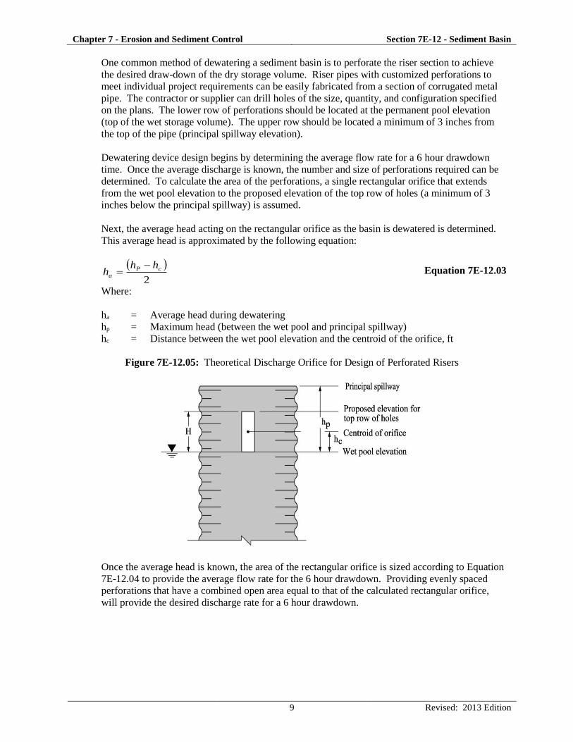
Next, the average head acting on the rectangular orifice as the basin is dewatered is determined.
This average head is approximated by the following equation:
2
cP
a
hhh
Equation 7E-12.03
Where:
ha = Average head during dewatering
hp = Maximum head (between the wet pool and principal spillway)
hc = Distance between the wet pool elevation and the centroid of the orifice, ft
Figure 7E-12.05: Theoretical Discharge Orifice for Design of Perforated Risers
Once the average head is known, the area of the rectangular orifice is sized according to Equation
7E-12.04 to provide the average flow rate for the 6 hour drawdown. Providing evenly spaced
perforations that have a combined open area equal to that of the calculated rectangular orifice,
will provide the desired discharge rate for a 6 hour drawdown.

Chapter 7 - Erosion and Sediment Control Section 7E-12 - Sediment Basin
10 Revised: 2013 Edition
21
26.0 a
a
hg
QA
Equation 7E-12.04
Where:
A = Total area of the orifices, sf
ha = Average head acting on the orifice (Equation 7E-12.03)
Qa = Average flow rate required for 6-hour drawdown, cfs
Q = S/21,600 sec. (6 hour drawdown only)
S = Dry storage volume required, cf
The number and diameter of the holes is variable. The diameter selected should be a minimum of
1 inch to minimize clogging, and should be a multiple of 1/4 of an inch. The perforation
configuration should consist of a minimum of three horizontal rows and two vertical columns of
evenly spaced perforations. Selecting a combination of hole diameter and number of holes is a
trial and error process. Once the configuration is determined, the required information should be
specified on the plans.
An alternative to the traditional riser is to provide a skimmer device that floats on the surface of
the water in the basin. The skimmer is made of a straight section of PVC pipe equipped with a
float and attached with a flexible coupling to an outlet at the base of the riser. Because the
skimmer floats, it rises and falls with the level of the water in the basin and drains only the
cleanest top layer of runoff. Sediment removal rates from basins equipped with skimmers have
been shown to be significantly more effective than with a perforated riser or orifice.
Skimming devices are normally proprietary. Discharge information should be obtained from the
manufacturer.

Chapter 7 - Erosion and Sediment Control Section 7E-12 - Sediment Basin
11 Revised: 2013 Edition
Figure 7E-12.06: Example Skimmer for Drawdown of Wet Storage
Source: Penn State University
5. Emergency Spillway: An emergency spillway acts as an overflow device for a sediment basin
by safely passing the large, less frequent storms through the basin without damage to the
embankment. It also acts in case of an emergency such as excessive sedimentation or damage to
the riser that prevents flow through the principal spillway. The emergency spillway should
consist of an open channel constructed adjacent to the embankment over undisturbed material, not
fill. This channel should be stabilized with matting, seeding, or sodding.
Where conditions will not allow the construction of an emergency spillway on undisturbed
material, the spillway may be constructed on top of the embankment and protected with non-
erodible material such as erosion stone.
An evaluation of site and downstream conditions must be made to determine the feasibility of,
and justification for, the incorporation of an emergency spillway. In some cases, the site
topography does not allow a spillway to be constructed in undisturbed material, and the
temporary nature of the facility may not warrant the cost of disturbing more acreage to construct
and armor an emergency spillway. The principal spillway should then be sized to convey a 25
year storm event, providing 2 feet of freeboard between the design high water elevation and the
top of the embankment. If the facility is designed to be permanent, the added expense of
constructing and armoring an emergency spillway may be justified.
When an emergency spillway is required, it should be designed to safely pass the 25 year design
storm with a minimum of one-foot clearance between the high water elevation and the top of the

Chapter 7 - Erosion and Sediment Control Section 7E-12 - Sediment Basin
12 Revised: 2013 Edition
basin embankment. Since the principal spillway is only designed to carry the 2 year event, the
emergency spillway must carry the remainder of the 25 year event.
p25e QQQ Equation 7E-12.05
Where:
Qe = Required emergency spillway capacity, cfs
Q25 = 25-year, 24 hour peak flow, cfs
Qp = Principal spillway capacity at high water elevation, cfs
Based upon the flow requirements, Table 7E-12.01 can be used to determine the minimum width
of the emergency spillway (b), the minimum slope of the exit channel (S), and the minimum
length of the exist channel (X).
A control section at least 20 feet in length should be provided in order to determine the hydraulic
characteristics of the spillway, according to Table 7E-12.01. The control section should be a
level portion of the spillway channel at the highest elevation in the channel. If the length and
slope of the exit channel indicated in Table 7E-12.01 cannot be provided, alternative methods of
evaluating the spillway must be conducted.

Chapter 7 - Erosion and Sediment Control Section 7E-12 - Sediment Basin
13 Revised: 2013 Edition
Figure 7E-12.07: Typical Sediment Basin Emergency Spillway
Source: Roberts, 1995

Chapter 7 - Erosion and Sediment Control Section 7E-12 - Sediment Basin
14 Revised: 2013 Edition
Table 7E-12.02: Design Data for Earthen Emergency Spillways
8 10 12 14 16 18 20 22 24 26 28 30 32 34 36 38 40Q 6 7 8 10 11 13 14 15 17 18 20 21 22 24 25 27 28V 2.7 2.7 2.7 2.7 2.7 2.7 2.7 2.7 2.7 2.7 2.7 2.7 2.7 2.7 2.7 2.7 2.7S 3.9 3.9 3.9 3.8 3.8 3.8 3.8 3.8 3.8 3.8 3.8 3.8 3.8 3.8 3.8 3.8 3.8X 32 33 33 33 33 33 33 33 33 33 33 33 33 33 33 33 33Q 8 10 12 14 16 18 20 22 24 26 28 30 32 34 35 37 39V 3 3 3 3 3 3 3 3 3 3 3 3 3 3 3 3 3S 3.7 3.7 3.7 3.7 3.6 3.7 3.6 3.6 3.6 3.6 3.6 3.6 3.6 3.6 3.6 3.6 3.6X 36 36 36 36 36 36 37 37 37 37 37 37 37 37 37 37 37Q 11 13 16 18 2 23 25 28 30 33 35 38 41 43 44 46 48V 3.2 3.2 3.3 3.3 3.3 3.3 3.3 3.3 3.3 3.3 3.3 3.3 3.3 3.3 3.3 3.3 3.3S 3.5 3.5 3.4 3.4 3.4 3.4 3.4 3.4 3.4 3.4 3.4 3.4 3.4 3.4 3.4 3.4 3.4X 39 40 40 40 41 41 41 41 41 41 41 41 41 41 41 41 4Q 13 16 19 22 26 29 32 35 38 42 45 46 48 51 54 57 60V 3.5 3.5 3.5 3.6 3.6 3.6 3.6 3.6 3.6 3.6 3.6 3.6 3.6 3.6 3.6 3.6 3.6S 3.3 3.3 3.3 3.2 3.2 3.2 3.2 3.2 3.2 3.2 3.2 3.2 3.2 3.2 3.2 3.2 3.2X 44 44 44 44 45 45 45 45 45 45 45 45 45 45 45 45 45Q 17 20 24 28 32 35 39 43 47 51 53 57 60 61 68 71 75V 3.7 3.8 3.8 3.8 3.8 3.8 3.8 3.8 3.8 3.8 3.8 3.8 3.8 3.8 3.8 3.8 3.8S 3.2 3.1 3.1 3.1 3.1 3.1 3.1 3.1 3.1 3.1 3.1 3.1 3.1 3.1 3.1 3.1 3.1X 47 47 48 48 48 48 48 48 48 48 49 49 49 49 49 49 49Q 20 24 29 33 38 42 47 51 56 61 63 68 72 77 81 86 90V 4 4 4 4 4 4 4 4 4 4 4 4 4 4 4 4 4S 3.1 3 3 3 3 3 3 3 3 3 3 3 3 3 3 3 3X 51 51 51 51 52 52 52 52 52 52 52 52 52 52 52 52 52Q 23 28 34 39 44 49 54 60 65 70 74 79 84 89 95 100 105V 4.2 4.2 4.2 4.3 4.3 4.3 4.3 4.3 4.3 4.3 4.3 4.3 4.3 4.3 4.3 4.3 4.3S 2.9 2.9 2.9 2.9 2.9 2.9 2.9 2.9 2.9 2.8 2.8 2.8 2.8 2.8 2.8 2.8 2.8X 55 55 55 55 55 55 55 56 56 56 56 56 56 56 56 56 56Q 28 33 40 45 51 58 64 69 76 80 86 92 98 104 110 116 122V 4.4 4.4 4.4 4.4 4.4 4.5 4.5 4.5 4.5 4.5 4.5 4.5 4.5 4.5 4.5 4.5 4.5S 2.9 2.9 2.8 2.8 2.8 2.8 2.8 2.8 2.8 2.8 2.8 2.8 2.8 2.8 2.8 2.8 2.8X 58 58 59 59 59 59 59 59 60 60 60 60 60 60 60 60 60Q 32 38 46 53 58 65 73 80 86 91 99 106 112 119 125 133 140V 4.5 4.6 4.6 4.6 4.6 4.6 4.7 4.7 4.7 4.7 4.7 4.7 4.7 4.7 4.7 4.7 4.7S 2.8 2.8 2.8 2.7 2.7 2.7 2.7 2.7 2.7 2.7 2.7 2.7 2.7 2.7 2.7 2.7 2.7X 62 62 62 63 63 63 63 63 63 63 63 64 64 64 64 64 64Q 37 44 51 59 66 74 82 90 96 103 111 119 127 134 142 150 158V 4.5 4.8 4.8 4.8 4.8 4.8 4.8 4.8 4.8 4.9 4.9 4.9 4.9 4.9 4.9 4.9 4.9S 2.8 2.7 2.7 2.7 2.7 2.7 2.7 2.6 2.6 2.6 2.6 2.6 2.6 2.6 2.6 2.6 2.6X 65 66 66 66 66 67 67 67 67 67 67 68 68 68 68 68 69Q 41 50 58 66 75 85 92 101 108 116 125 133 142 150 160 169 178V 4.8 4.9 4.9 5 5 5 5 5 5 5 5 5 5 5 5.1 5.1 5.1S 2.7 2.7 2.6 2.6 2.6 2.6 2.6 2.6 2.6 2.6 2.6 2.6 2.6 2.6 2.5 2.5 2.5X 69 69 70 70 71 71 71 71 71 71 71 72 72 72 72 72 72Q 46 56 65 75 84 94 104 112 122 132 142 149 158 168 178 187 197V 5 5.1 5.1 5.1 5.1 5.2 5.2 5.2 5.2 5.2 5.2 5.2 5.2 5.2 5.2 5.2 5.2S 2.6 2.6 2.6 2.6 2.5 2.5 2.5 2.5 2.5 2.5 2.5 2.5 2.5 2.5 2.5 2.5 2.5X 72 74 74 75 75 76 76 76 76 76 76 76 76 76 76 76 76Q 52 62 72 83 94 105 115 126 135 145 156 167 175 187 196 206 217V 5.2 5.2 5.2 5.3 5.3 5.3 5.3 5.4 5.4 5.4 5.4 5.4 5.4 5.4 5.4 5.4 5.4S 2.6 2.6 2.5 2.5 2.5 2.5 2.5 2.5 2.5 2.5 2.5 2.5 2.5 2.5 2.5 2.5 2.5X 76 78 79 80 80 80 80 80 80 80 80 80 80 80 80 80 80Q 58 69 81 93 104 116 127 138 150 160 171 182 194 204 214 226 233V 5.3 5.4 5.4 5.5 5.5 5.5 5.5 5.5 5.5 5.5 5.5 5.6 5.6 5.6 5.6 5.6 5.6S 2.5 2.5 2.5 2.5 2.4 2.4 2.4 2.4 2.4 2.4 2.4 2.4 2.4 2.4 2.4 2.4 2.4X 80 82 83 84 84 84 84 84 84 84 84 84 84 84 84 84 84Q 64 76 88 102 114 127 140 152 164 175 188 201 213 225 235 246 260V 5.5 5.5 5.5 5.6 5.6 5.6 5.7 5.7 5.7 5.7 5.7 5.7 5.7 5.7 5.7 5.7 5.7S 2.5 2.5 2.5 2.4 2.4 2.4 2.4 2.4 2.4 2.4 2.4 2.4 2.4 2.4 2.4 2.4 2.4X 84 85 86 87 88 88 88 88 88 88 88 88 88 88 88 88 88Q 71 83 97 111 125 138 153 164 178 193 204 218 232 245 256 269 283V 5.6 5.7 5.7 5.7 5.8 5.8 5.8 5.8 5.8 5.8 5.8 5.9 5.9 5.9 5.9 5.9 5.9S 2.5 2.4 2.4 2.4 2.4 2.4 2.4 2.4 2.3 2.3 2.3 2.3 2.3 2.3 2.3 2.3 2.3X 88 90 91 91 91 91 91 92 92 92 92 92 92 92 92 92 92
Q=Spillway Capacity, cfs V=Velocity, fps
S=Minimum downstream embankment slope, % X=Minimum length of the exit channel, ft
Bottom Width (b) in feet
0.5
1.0
1.2
Spillway
Variables
Stage
(Hp) in feet
0.6
1.3
0.9
Data to the right of the heavy vertical lines should be used with caution, as the resulting sections will
1.7
1.5
0.7
0.8
be either poorly proportioned, or have velocities in excess of 6 feet per second
1.1
1.9
2.0
1.6
1.8
1.4
Source: Roberts, 1995

Chapter 7 - Erosion and Sediment Control Section 7E-12 - Sediment Basin
15 Revised: 2013 Edition
In addition to checking the capacity of the spillway, the discharge velocity should also be
considered. The allowable velocity for vegetated channels or channels lined with a turf
reinforcement mat should be carefully analyzed. See Section 7E-23 and 7E-18 for information on
permissible velocities. For non-erodible linings such as concrete or rip rap, design velocities may
be increased.
5. Anti-seep Collars: Anti-seep collars help prevent water from flowing along the interface
between the outlet barrel and the embankment. This movement of water can, over time,
destabilize the embankment, causing it to wash out or burst.
Anti-seep collars are not normally required for sediment basins. However, when the height of the
embankment exceeds 10 feet, or the embankment material has a low silt-clay content, anti-seep
collars should be used. Anti-seep collars should be used on all structures that may be converted
to permanent features.
The first step in designing anti-seep collars is to determine the length of the barrel within the
saturated zone. The length of the saturated zone is determined with the following:
S
SZYLS
25.014 Equation 7E-12.06
Where:
Ls = Length of the barrel within saturated zone, ft
Y = Depth of water at principal spillway crest, ft
Z Slope of upstream face of embankment, Z ft H: 1 ft V.
S = Slope of the barrel in ft per ft
An increase in the seepage length along the barrel of 10% should be provided. Determine the
length required to achieve this by multiplying Ls by 10% (0.10LS). This increase in length
represents the total collar projection. This can be provided for by one or multiple collars.
Choose a collar size that is at least 4 feet larger than the barrel diameter (2 feet in all directions).
Calculate the collar projection by subtracting the pipe diameter from the collar size. Then
determine the number of collars required by dividing the seepage length increase (0.10LS) by the
collar projection. To reduce the number of collars required, the collar size can be increased.
Alternatively, providing more collars can decrease the collar size.
Collars should be placed at a maximum spacing of 14 times the minimum projection above the
pipe, and a minimum spacing of 5 times the minimum projection. All collars should be located
within the saturated zone. If spacing will not allow this, at least one collar should be located
within the saturated zone.
Alternative methods of controlling seepage, such as a filter diaphragm may also be acceptable. A
filter diaphragm consists of a layer of porous material running perpendicular to the outlet barrel
which intercepts and controls water movement and fines migration within the embankment.

Chapter 7 - Erosion and Sediment Control Section 7E-12 - Sediment Basin
16 Revised: 2018 Edition
Figure 7E-12.08: Anti-seep Collar
(SUDAS Specifications Figure 9040.117)
Source: Adapted from Virginia DCR, 1999

Chapter 7 - Erosion and Sediment Control Section 7E-12 - Sediment Basin
17 Revised: 2013 Edition
7. Safety Fence: Depending on the depth, location, and local ordinances, a safety fence and
appropriate signing may be required around the sediment basin.
8. Additional Considerations: Sediment basins which are more than 10 feet high, or which have
storage capacities in excess of 10 acre-feet may require review and approval from the Iowa DNR
per IAC 567-71.3. A vast majority of temporary sediment basins will not fall under these
regulations. Basins that are intended to become permanent features are more likely to require this
review.
C. Application
Sediment basin volumes and dimensions should be sized according to the criteria in Section 7D-1.
Sediment basins are normally required for disturbed drainage areas of 10 acres or greater.
D. Maintenance
Maintenance and cleanout frequencies for sediment basins depend greatly on the amount of
precipitation and sediment load arriving at the basin. During inspections, the embankment should be
reviewed for signs of seepage, settlement, or slumping. These problems should be repaired
immediately. Sediment should be removed from the basin when it accumulates to one-half of the wet
storage volume.
During sediment cleanout, trash should be removed from the basin, and the dewatering device and
riser pipe should be checked and cleared of any accumulated debris.
E. Design Example
Assume a construction site has 12 acres of disturbed ground which drains to a common location. In
addition, 8 acres of off-site area drains through the construction site. Due to site restrictions, the 8
acres of off-site drainage cannot be routed around the site. Design a temporary sediment basin, with
and emergency spillway, to handle and treat the runoff from the 20 acre site.
Solution:
1. Basin Volume: The Iowa DNR NPDES General Permit No. 2 requires a minimum storage
volume of 3,600 cubic feet of storage per acre drained.
Therefore: 20 acres x 3,600 cf = 72,000 cf.
According to Section 7D-1, D, 3, this volume should be split equally between wet and dry storage
(36,000 cf each).
For the remaining calculations, assume that a basin has been sized and laid out to provide the
following elevations:
Elevation A (Bottom of Basin) = 100
Elevation B (Wet Storage) = 103.0
Elevation C (Dry Storage) 105.0
Elevation D (Invert of emergency spillway) = 106.5
Elevation E (Top of embankment) = 108.5

Chapter 7 - Erosion and Sediment Control Section 7E-12 - Sediment Basin
18 Revised: 2013 Edition
2. Size the Principal Spillway (Riser): From TR-55, using the methods described in Chapter 2 -
Stormwater, assume the peak inflow from the 2 year, 24 hour storm is 41 cfs.
In order to determine the required diameter of the principal spillway, the available head elevation
above the spillway must be determined. From the elevation information provided above, the
principal spillway is at elevation 105.0, and the invert of the emergency spillway is at elevation
106.5. Based upon this, the allowable head is 1.5 feet (106.5-105.0).
The diameter of principal spillway (riser) is found by trial and error process, with the weir and
orifice equations:
Try a 24 inch diameter riser: (d=2 ft, A=3.14 ft2)
Weir Flow Orifice Flow
2
3
hd5.10Q gh2A6.0Q
395.125.10 2
3
Q cfs 195.12.32214.36.0 Q cfs
The lower flow rate (orifice) controls at 19 cfs. The design flow rate was 41 cfs; therefore,
the proposed 24 inch riser is too small. Try a larger diameter.
Try a 36 inch diameter riser. (d=3’, A=7.1 ft2)
Weir Flow Orifice Flow
585.135.10 2
3
Q cfs 425.12.3221.76.0 Q cfs
The lower flow rate (orifice) controls at 42 cfs. This is greater than the design flow. Select a
36 inch diameter riser pipe for the principal spillway.
3. Size the Dewatering Orifice: To dewater 36,000 cubic feet, the average discharge, Qa, is found
as follows:
7.160606
000,36
aQ cfs.
Next, determine the average head acting on the perforations during dewatering. Assume a
rectangular orifice extends from the lowest set of perforations at the wet storage elevation
(103.0), up to the upper row of perforations, 3 inches below the principal spillway
(105.0-0.25 = 104.75). Based upon this, the maximum head, hp, is 2 feet (105-103) and the
distance to the centroid of the orifice is 0.875 feet [(104.75-103)/2].
From Equation 7E-12.03, the average head acting on the openings is:
2
cP
a
hhh
=
56.0
2
875.02
feet

Chapter 7 - Erosion and Sediment Control Section 7E-12 - Sediment Basin
19 Revised: 2013 Edition
Once the average head and average discharge are known, the total orifice area can be calculated
from Equation 7E-12.04:
21
26.0 a
a
hg
QA
47.0
56.02.3226.0
7.1
21
sf
Several perforation configurations could provide this area. One feasible selection would be to
provide 18, 2 1/4 inch holes in three rows (6 holes per row).
4. Size the Emergency Spillway: Since this basin will have an emergency spillway, the principal
spillway (riser) was only designed only to carry the 2 year storm. Larger storms, which exceed
the capacity of the principal spillway, will be carried by the emergency spillway. The emergency
spillway will be designed to carry the 25 year storm event.
From TR-55, using the methods described in Chapter 2 - Stormwater, assume the inflow from the
25 year storm is 99 cfs.
During high flow events, both the principal spillway and the emergency spillway will be
bypassing flow from the basin. From step 2, the capacity of the principal spillway is 42 cfs.
Therefore, from Equation 7E-12.05, the required capacity of the emergency spillway is as
follows:
57429925 pe QQQ cfs
The capacity of the emergency spillway must be at least 57 cfs. From the assumptions above, the
difference in elevation between the invert of the emergency spillway, and the top of the
embankment is 2 feet. Since a minimum of 1 foot must be provided between the design high-
water elevation and the top of the embankment, 1 foot of head is available for discharge across
the spillway.
From Table 7E-12.01, find the discharge (Q) that equals or exceeds the design value of 57 cfs.
From the table, for 1-foot of head, move horizontally to the discharge value of 61 cfs. Moving
vertically in the table, the corresponding width for a discharge of 61 cfs is 26 feet.
5. Design Example Summary:
Basin Volume: 72,000 cubic feet (split equally between wet and dry storage)
Principal Spillway Diameter: 36 inches
Dewatering Device: 18, 2 1/4 inch holes in 3 rows (6 holes per row)
Emergency Spillway Width: 26 feet