section a engine: kubota - sgs engineering · contents page no. machine / engine type table a.3...
TRANSCRIPT
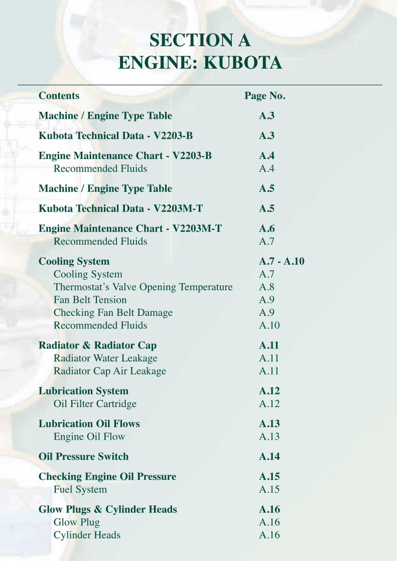
Contents Page No.
Machine / Engine Type Table A.3
Kubota Technical Data - V2203-B A.3
Engine Maintenance Chart - V2203-B A.4Recommended Fluids A.4
Machine / Engine Type Table A.5
Kubota Technical Data - V2203M-T A.5
Engine Maintenance Chart - V2203M-T A.6Recommended Fluids A.7
Cooling System A.7 - A.10Cooling System A.7Thermostat’s Valve Opening Temperature A.8Fan Belt Tension A.9Checking Fan Belt Damage A.9Recommended Fluids A.10
Radiator & Radiator Cap A.11Radiator Water Leakage A.11Radiator Cap Air Leakage A.11
Lubrication System A.12Oil Filter Cartridge A.12
Lubrication Oil Flows A.13Engine Oil Flow A.13
Oil Pressure Switch A.14
Checking Engine Oil Pressure A.15Fuel System A.15
Glow Plugs & Cylinder Heads A.16Glow Plug A.16Cylinder Heads A.16
SECTION A ENGINE: KUBOTA
Contents Page No.
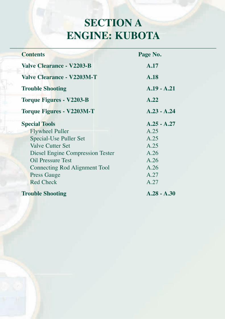
Valve Clearance - V2203-B A.17
Valve Clearance - V2203M-T A.18
Trouble Shooting A.19 - A.21
Torque Figures - V2203-B A.22
Torque Figures - V2203M-T A.23 - A.24
Special Tools A.25 - A.27Flywheel Puller A.25Special-Use Puller Set A.25Valve Cutter Set A.25Diesel Engine Compression Tester A.26Oil Pressure Test A.26Connecting Rod Alignment Tool A.26Press Gauge A.27Red Check A.27
Trouble Shooting A.28 - A.30
SECTION A ENGINE: KUBOTA
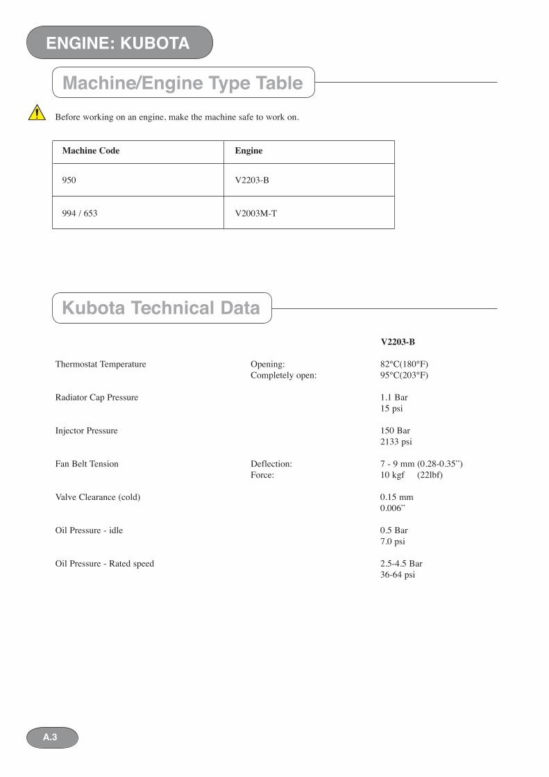
V2203-B Thermostat Tem per a ture Opening: 82°C(180°F) Completely open: 95°C(203°F)
Radiator Cap Pressure 1.1 Bar 15 psi
Injector Pressure 150 Bar 2133 psi
Fan Belt Tension Deflection: 7 - 9 mm (0.28-0.35”) Force: 10 kgf (22lbf)
Valve Clearance (cold) 0.15 mm 0.006”
Oil Pressure - idle 0.5 Bar 7.0 psi
Oil Pressure - Rated speed 2.5-4.5 Bar 36-64 psi
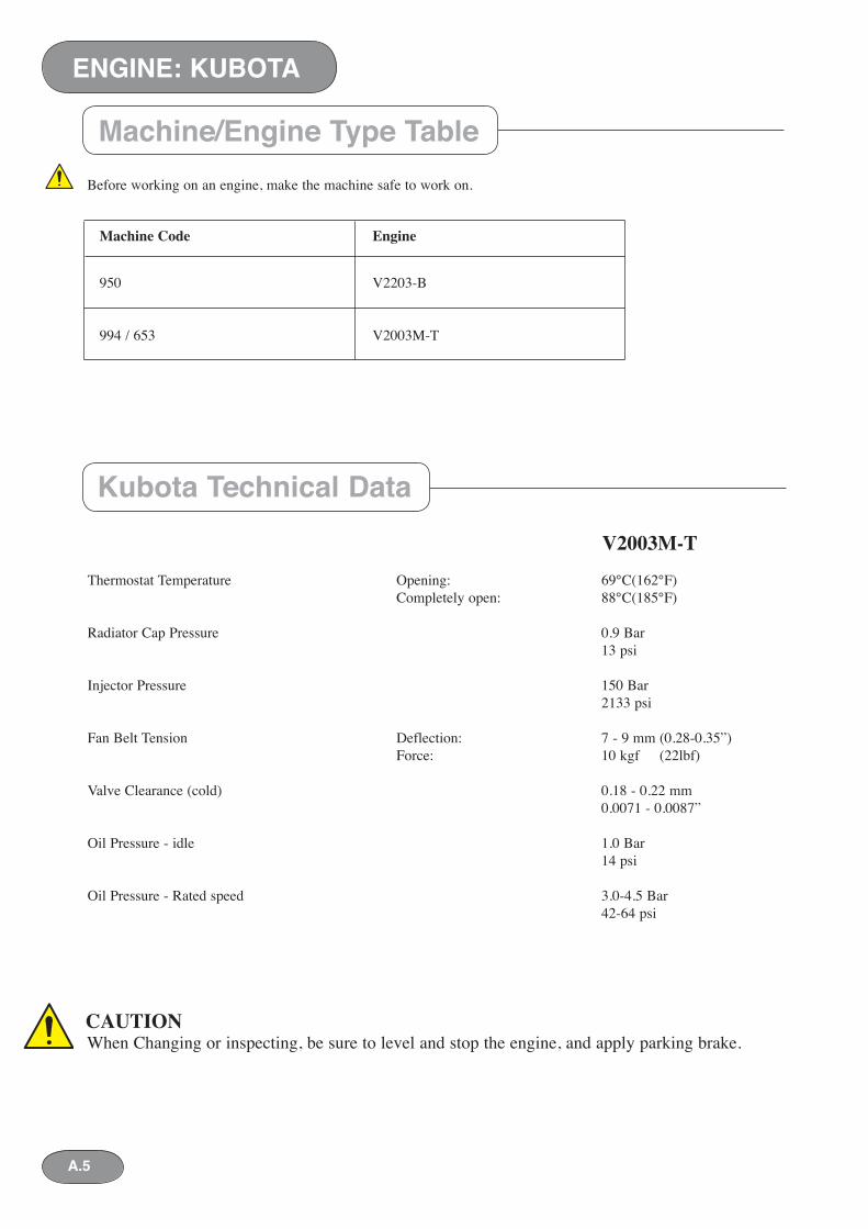
Machine/Engine Type Table
Kubota Technical Data
Machine Code Engine
950 V2203-B
994 / 653 V2003M-T
Before working on an engine, make the machine safe to work on.
A.3
ENGINE: KUBOTASECTION A ENGINE: KUBOTA
ENGINE: KUBOTA
A.4
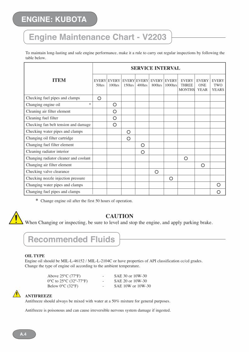
* Change engine oil after the first 50 hours of operation.
CAUTIONWhen Changing or inspecting, be sure to level and stop the engine, and apply parking brake.
OIL TYPEEngine oil should be MIL-L-46152 / MIL-L-2104C or have properties of API classification cc/cd grades.Change the type of engine oil according to the ambient temperature.
Above 25°C (77°F) - SAE 30 or 10W-30 0°C to 25°C (32°-77°F) - SAE 20 or 10W-30 Below 0°C (32°F) - SAE 10W or 10W-30
ANTIFREEZEAntifreeze should always be mixed with water at a 50% mixture for general purposes.
Antifreeze is poisonous and can cause irreversible nervous system damage if ingested.
To maintain long-lasting and safe engine performance, make it a rule to carry out regular in spec tions by following the table below.
Engine Maintenance Chart - V2203
Recommended Fluids
SERVICE INTERVAL
ITEM EVERY EVERY EVERY EVERY EVERY EVERY EVERY EVERY EVERY 50hrs 100hrs 150hrs 400hrs 800hrs 1000hrs THREE ONE TWO MONTHS YEAR YEARS
Checking fuel pipes and clampsChanging engine oil * Cleaning air filter elementCleaning fuel filterChecking fan belt tension and damageChecking water pipes and clampsChanging oil filter cartridgeChanging fuel filter elementCleaning radiator interiorChanging radiator cleaner and coolantChanging air filter elementChecking valve clearanceChecking nozzle injection pressureChanging water pipes and clampsChanging fuel pipes and clamps
A.5
ENGINE: KUBOTA
V2003M-T Thermostat Tem per a ture Opening: 69°C(162°F) Completely open: 88°C(185°F)
Radiator Cap Pressure 0.9 Bar 13 psi
Injector Pressure 150 Bar 2133 psi
Fan Belt Tension Deflection: 7 - 9 mm (0.28-0.35”) Force: 10 kgf (22lbf)
Valve Clearance (cold) 0.18 - 0.22 mm 0.0071 - 0.0087”
Oil Pressure - idle 1.0 Bar 14 psi
Oil Pressure - Rated speed 3.0-4.5 Bar 42-64 psi
Machine/Engine Type Table
Kubota Technical Data
Machine Code Engine
950 V2203-B
994 / 653 V2003M-T
Before working on an engine, make the machine safe to work on.
CAUTIONWhen Changing or inspecting, be sure to level and stop the engine, and apply parking brake.
ENGINE: KUBOTA
A.6
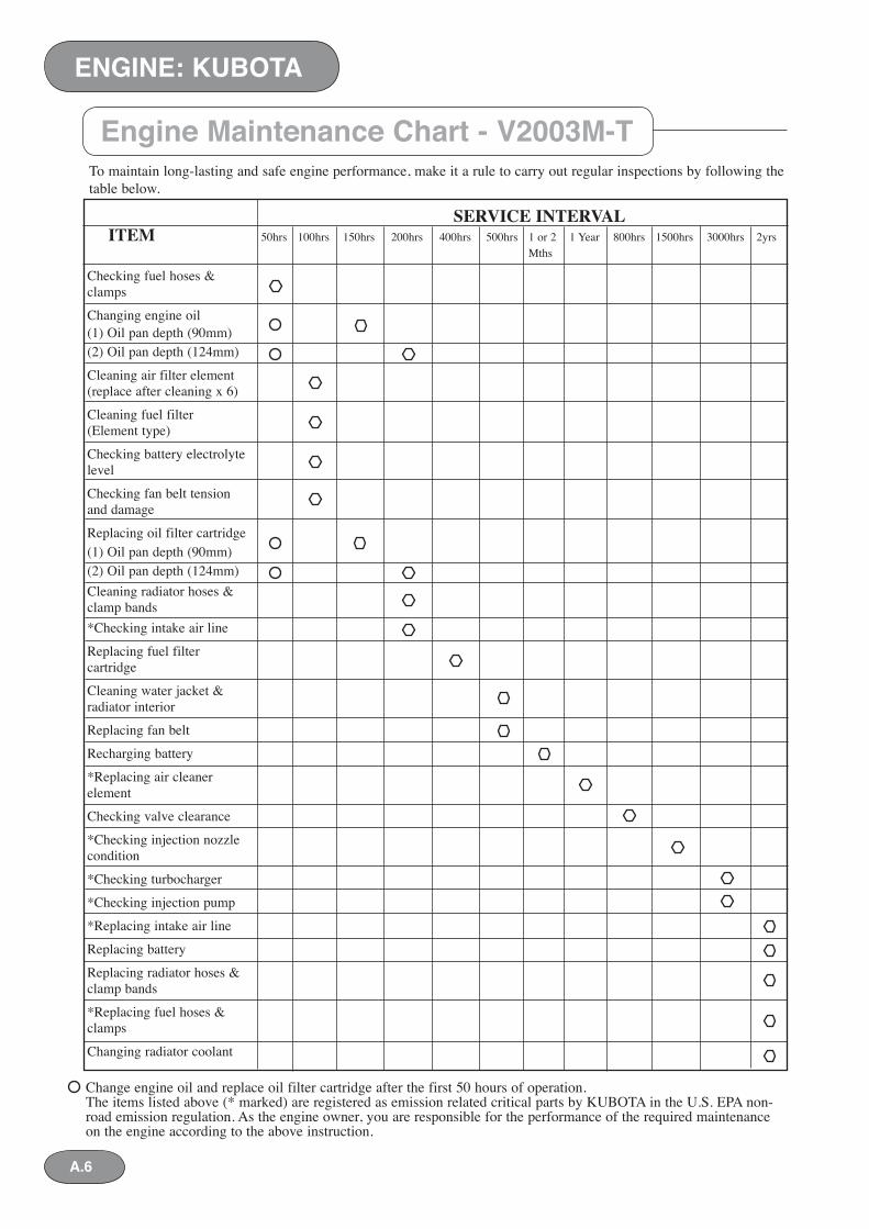
Change engine oil and replace oil filter cartridge after the first 50 hours of operation.The items listed above (* marked) are registered as emission related critical parts by KUBOTA in the U.S. EPA non-road emission regulation. As the engine owner, you are responsible for the performance of the required maintenance on the engine according to the above instruction.
To maintain long-lasting and safe engine performance, make it a rule to carry out regular in spec tions by following the table below.
Engine Maintenance Chart - V2003M-T
SERVICE INTERVAL ITEM 50hrs 100hrs 150hrs 200hrs 400hrs 500hrs 1 or 2 1 Year 800hrs 1500hrs 3000hrs 2yrs Mths
Checking fuel hoses & clamps
Changing engine oil(1) Oil pan depth (90mm)(2) Oil pan depth (124mm)
Cleaning air filter element(replace after cleaning x 6)
Cleaning fuel filter (Element type)
Checking battery electrolyte level
Checking fan belt tensionand damage
Replacing oil filter cartridge(1) Oil pan depth (90mm)(2) Oil pan depth (124mm)Cleaning radiator hoses &clamp bands*Checking intake air line Replacing fuel filter cartridge
Cleaning water jacket & radiator interior
Replacing fan belt
Recharging battery
*Replacing air cleaner element
Checking valve clearance
*Checking injection nozzlecondition
*Checking turbocharger
*Checking injection pump
*Replacing intake air line
Replacing battery
Replacing radiator hoses &clamp bands
*Replacing fuel hoses & clamps
Changing radiator coolant
A.7
ENGINE: KUBOTA
Cooling System
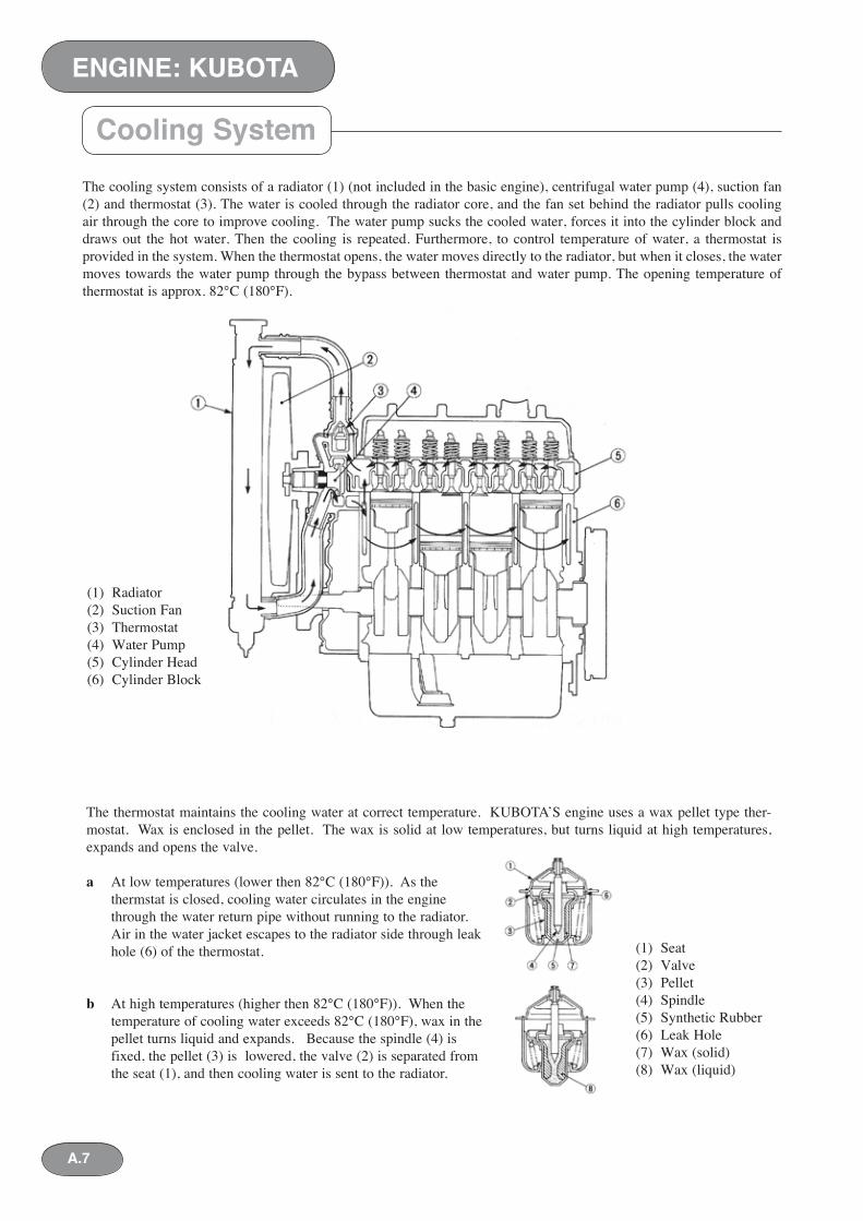
(1) Radiator(2) Suction Fan(3) Thermostat(4) Water Pump(5) Cylinder Head(6) Cylinder Block
The cooling system consists of a radiator (1) (not included in the basic engine), centrifugal water pump (4), suction fan (2) and thermostat (3). The water is cooled through the radiator core, and the fan set behind the radiator pulls cooling air through the core to improve cooling. The water pump sucks the cooled water, forces it into the cylinder block and draws out the hot water. Then the cooling is repeated. Furthermore, to control temperature of water, a thermostat is provided in the system. When the ther mo stat opens, the water moves directly to the radiator, but when it closes, the water moves towards the water pump through the bypass between thermostat and water pump. The opening tem per a ture of thermostat is approx. 82°C (180°F).
The thermostat maintains the cooling water at correct temperature. KUBOTA’S engine uses a wax pellet type ther-mostat. Wax is enclosed in the pellet. The wax is solid at low temperatures, but turns liquid at high temperatures, expands and opens the valve.
a At low temperatures (lower then 82°C (180°F)). As the thermstat is closed, cooling water cir cu lates in the engine through the water return pipe without running to the radiator. Air in the water jacket escapes to the radiator side through leak hole (6) of the thermostat.
b At high temperatures (higher then 82°C (180°F)). When the temperature of cooling water ex ceeds 82°C (180°F), wax in the pellet turns liquid and expands. Because the spindle (4) is fixed, the pellet (3) is low ered, the valve (2) is separated from the seat (1), and then cooling water is sent to the radiator.
(1) Seat(2) Valve(3) Pellet(4) Spindle(5) Synthetic Rubber(6) Leak Hole(7) Wax (solid)(8) Wax (liquid)
ENGINE: KUBOTA
A.8
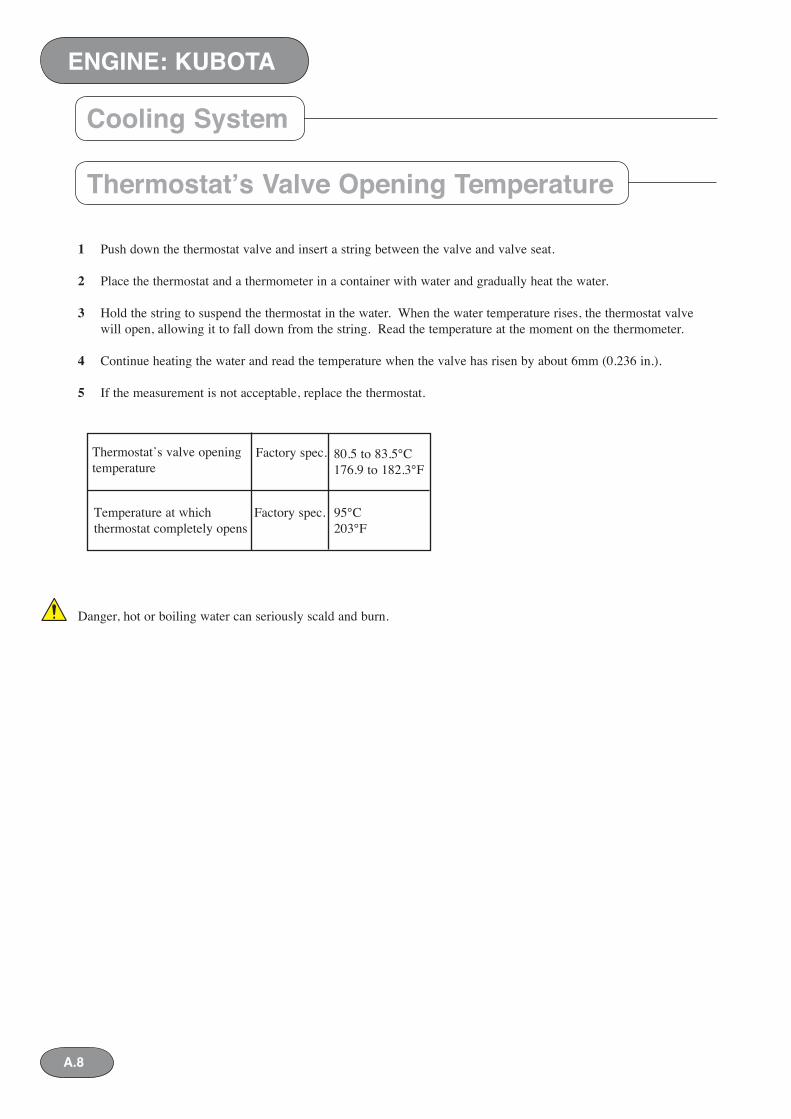
1 Push down the thermostat valve and insert a string between the valve and valve seat.
2 Place the thermostat and a thermometer in a container with water and gradually heat the water.
3 Hold the string to suspend the thermostat in the water. When the water temperature rises, the thermostat valve will open, allowing it to fall down from the string. Read the temperature at the moment on the thermometer.
4 Continue heating the water and read the temperature when the valve has risen by about 6mm (0.236 in.).
5 If the measurement is not acceptable, replace the thermostat.
Danger, hot or boiling water can seriously scald and burn.
Thermostat’s Valve Opening Temperature
Thermostat’s valve opening temperature
Factory spec. 80.5 to 83.5°C176.9 to 182.3°F
Temperature at which thermostat completely opens
Factory spec. 95°C203°F
Cooling System
A.9
ENGINE: KUBOTA
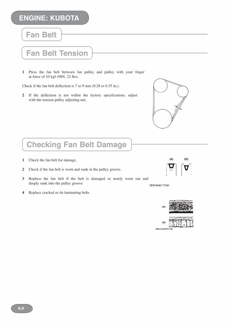
1 Press the fan belt between fan pulley and pulley with your finger at force of 10 kgf (98N, 22 lbs).
Check if the fan belt deflection is 7 to 9 mm (0.28 to 0.35 in.).
2 If the deflection is not within the factory specifications, adjust with the tension pulley ad just ing nut.
1 Check the fan belt for damage.
2 Check if the fan belt is worn and sunk in the pul ley groove.
3 Replace the fan belt if the belt is damaged or nearly worn out and deeply sunk into the pulley groove
4 Replace cracked or de-laminating belts.
Fan Belt Tension
Checking Fan Belt Damage
Fan Belt
ENGINE: KUBOTA
A.10
OIL TYPEEngine oil should be CF-4, CG-4 for low sulphur fuel on-road engines or have properties of API classification cc/cd grades. When an off-road vehicle engine runs on high sulphur fuel, it is advisable to use CF, CD or CE lubricat-ing oil with a high total base number. Change the type of engine oil according to the ambient temperature.
Above 25°C (77°F) - SAE 30 or 10W-30 0°C to 25°C (32°-77°F) - SAE 20 or 10W-30 Below 0°C (32°F) - SAE 10W or 10W-30ANTIFREEZEAntifreeze should always be mixed with water at a 50% mixture for general purposes.Antifreeze is poisonous and can cause irreversible nervous system damage if ingested.
Recommended Fluids
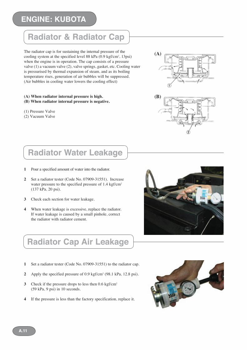
The radiator cap is for sustaining the internal pressure of the cooling system at the specified level 88 kPa (0.9 kgf/cm2, 13psi) when the en gine is in operation. The cap consists of a pres sure valve (1) a vacuum valve (2), valve springs, gasket, etc. Cooling water is pressurised by ther mal expansion of steam, and as its boiling tem per a ture rises, generation of air bubbles will be suppressed. (Air bubbles in cooling water low ers the cooling effect)
(A) When radiator internal pressure is high.(B) When radiator internal pressure is neg a tive.
(1) Pressure Valve(2) Vacuum Valve
1 Pour a specified amount of water into the ra di a tor.
2 Set a radiator tester (Code No. 07909-31551). In crease water pressure to the specified pres sure of 1.4 kgf/cm2 (137 kPa, 20 psi).
3 Check each section for water leakage.
4 When water leakage is excessive, replace the ra di a tor. If water leakage is caused by a small pinhole, correct the radiator with radiator ce ment.
1 Set a radiator tester (Code No. 07909-31551) to the radiator cap.
2 Apply the specified pressure of 0.9 kgf/cm2 (98.1 kPa, 12.8 psi).
3 Check if the pressure drops to less then 0.6 kgf/cm2 (59 kPa, 9 psi) in 10 seconds.
4 If the pressure is less than the factory spec i fi ca tion, replace it.
Radiator & Radiator Cap
ENGINE: KUBOTA
Radiator Water Leakage
Radiator Cap Air Leakage
A.11
(B)
(A)
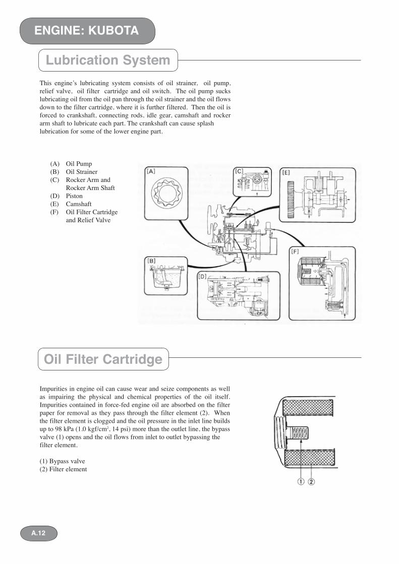
This engine’s lubricating system consists of oil strainer, oil pump, relief valve, oil filter cartridge and oil switch. The oil pump sucks lubricating oil from the oil pan through the oil strainer and the oil flows down to the filter cartridge, where it is further filtered. Then the oil is forced to crank shaft, connecting rods, idle gear, camshaft and rocker arm shaft to lubricate each part. The crankshaft can cause splash lubrication for some of the lower engine part.
Impurities in engine oil can cause wear and seize components as well as impairing the physical and chem i cal properties of the oil itself. Impurities con tained in force-fed engine oil are absorbed on the filter paper for re mov al as they pass through the fil ter el e ment (2). When the filter element is clogged and the oil pressure in the inlet line builds up to 98 kPa (1.0 kgf/cm2, 14 psi) more than the outlet line, the bypass valve (1) opens and the oil flows from inlet to outlet bypassing the filter element.
(1) Bypass valve(2) Filter element
Lubrication System
Oil Filter Cartridge
(A) Oil Pump(B) Oil Strainer(C) Rocker Arm and Rocker Arm Shaft(D) Piston(E) Camshaft(F) Oil Filter Cartridge and Relief Valve
ENGINE: KUBOTA
A.12
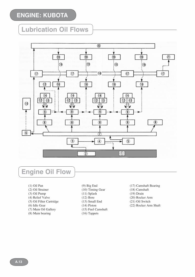
Lubrication Oil Flows
ENGINE: KUBOTA
Engine Oil Flow
A.13
(1) Oil Pan (9) Big End (17) Cam shaft Bearing (2) Oil Strainer (10) Timing Gear (18) Camshaft (3) Oil Pump (11) Splash (19) Drain (4) Relief Valve (12) Bore (20) Rocker Arm(5) Oil Filter Cartridge (13) Small End (21) Oil Switch (6) Idle Gear (14) Piston (22) Rocker Arm Shaft (7) Main Oil Gallery (15) Fuel Camshaft (8) Main bearing (16) Tappets
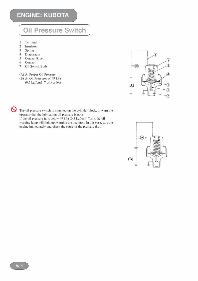
1 Terminal2 Insulator3 Spring4 Diaphragm5 Contact Rivet6 Contact7 Oil Switch Body
(A) At Proper Oil Pressure(B) At Oil Pressures of 49 kPa (0.5 kgf/cm2, 7 psi) or less
The oil pressure switch is mounted on the cyl in der block, to warn the operator that the lu bri cat ing oil pressure is poor.If the oil pressure falls below 49 kPa (0.5 kgf/cm2, 7psi), the oil warning lamp will light up, warning the operator. In this case, stop the en gine immediately and check the cause of the pres sure drop.
Oil Pressure Switch
(B)
(A)
ENGINE: KUBOTA
A.14
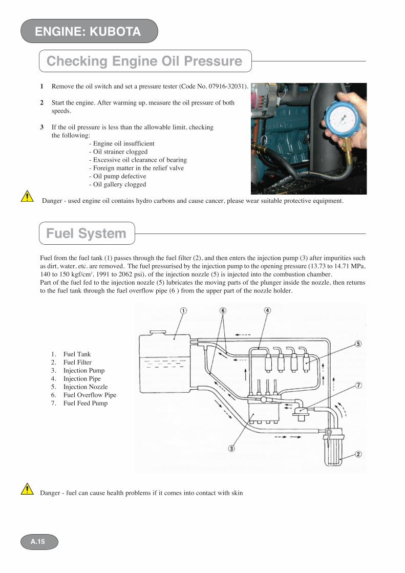
1 Remove the oil switch and set a pressure tester (Code No. 07916-32031).
2 Start the engine. After warming up, measure the oil pressure of both idling and rated speeds.
3 If the oil pressure is less than the allowable limit, checking the following: - Engine oil insufficient - Oil strainer clogged - Excessive oil clearance of bearing - Foreign matter in the relief valve - Oil pump defective - Oil gallery clogged
Danger - used engine oil contains hydro carbons and cause cancer, please wear suitable protective equipment.
Fuel from the fuel tank (1) passes through the fuel filter (2), and then enters the injection pump (3) after impurities such as dirt, water, etc. are removed. The fuel pressurised by the injection pump to the opening pressure (13.73 to 14.71 MPa, 140 to 150 kgf/cm2, 1991 to 2062 psi), of the injection nozzle (5) is in ject ed into the combustion chamber. Part of the fuel fed to the injection nozzle (5) lubricates the moving parts of the plunger inside the nozzle, then returns to the fuel tank through the fuel over flow pipe (6 ) from the upper part of the nozzle holder.
Danger - fuel can cause health problems if it comes into contact with skin
1. Fuel Tank2. Fuel Filter3. Injection Pump4. Injection Pipe5. Injection Nozzle6. Fuel Overflow Pipe7. Fuel Feed Pump
Checking Engine Oil Pressure
ENGINE: KUBOTA
Fuel System
A.15
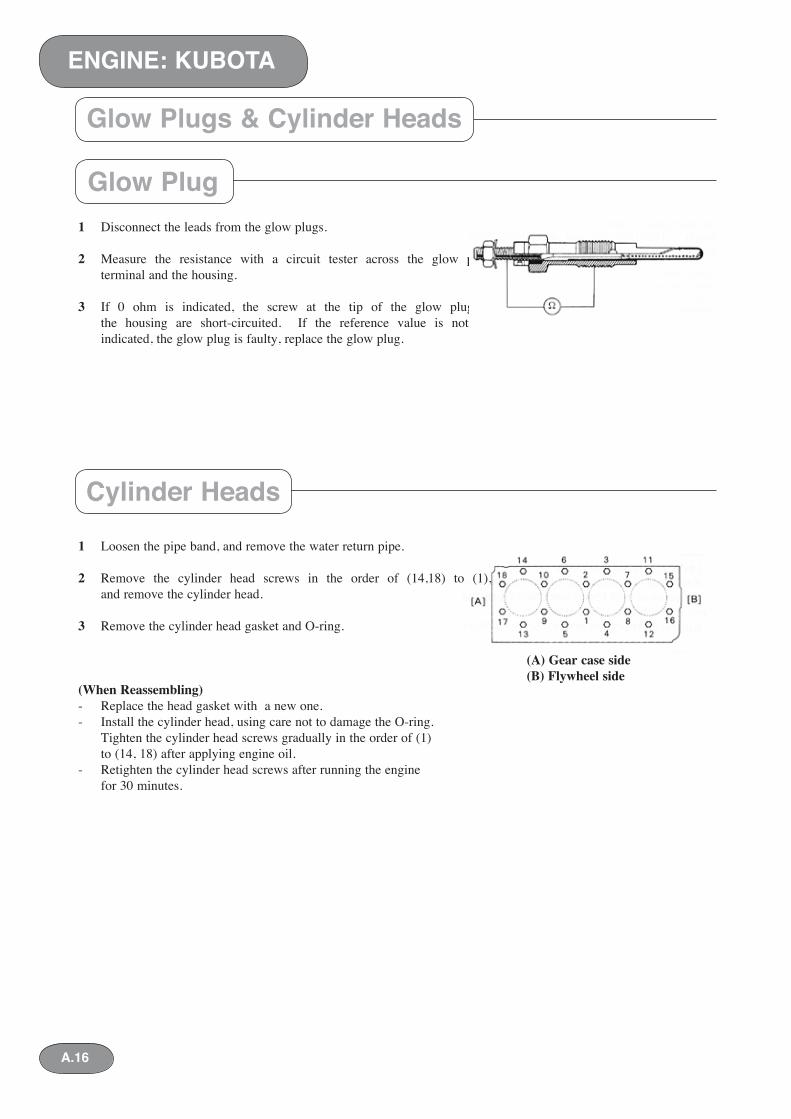
1 Disconnect the leads from the glow plugs.
2 Measure the resistance with a circuit tester across the glow plug terminal and the housing.
3 If 0 ohm is indicated, the screw at the tip of the glow plug and the housing are short-circuited. If the reference value is not indicated, the glow plug is faulty, replace the glow plug.
1 Loosen the pipe band, and remove the water return pipe.
2 Remove the cylinder head screws in the order of (14,18) to (1), and remove the cyl in der head.
3 Remove the cylinder head gasket and O-ring.
(When Reassembling)- Replace the head gasket with a new one.- Install the cylinder head, using care not to damage the O-ring. Tighten the cylinder head screws gradually in the order of (1) to (14, 18) after applying engine oil.- Retighten the cylinder head screws after running the engine for 30 minutes.
Glow Plug
Cylinder Heads
(A) Gear case side(B) Flywheel side
Glow Plugs & Cylinder Heads
ENGINE: KUBOTA
A.16
Checking Valve Clearance - V-2203-B
ENGINE: KUBOTA
A.17
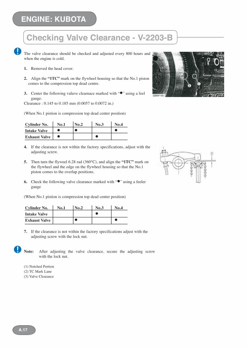
The valve clearance should be checked and adjusted every 800 hours and when the engine is cold.
1. Removed the head cover.
2. Align the “1TC” mark on the flywheel housing so that the No.1 piston comes to the compression top dead centre.
3. Center the following valuve clearnace marked with “•” using a feel gauge.Clearance : 0.145 to 0.185 mm (0.0057 to 0.0072 in.)
(When No.1 pistion is compression top dead center position)
Cylinder No. No.1 No.2 No.3 No.4Intake Valve • • •Exhaust Valve • •
4. If the clearance is not within the factory specifications, adjust with the adjusting screw.
5. Then turn the flyweel 6.28 rad (360°C), and align the “1TC” mark on the flywheel and the edge on the flywheel housing so that the No.1
piston comes to the overlap positions.
6. Check the following valve clearance marked with “•” using a feeler gauge
(When No.1 pistion is compression top dead center position)
Cylinder No. No.1 No.2 No.3 No.4Intake Valve •Exhaust Valve • •
7. If the clearance is not within the factory specifications adjust with the adjusting screw with the lock nut.
Note: After adjusting the valve clearance, secure the adjusting screw with the lock nut.
(1) Notched Portion(2) TC Mark Lane(3) Valve Clearance
!
!
Checking Valve Clearance - V-2003M-T
ENGINE: KUBOTA
A.18
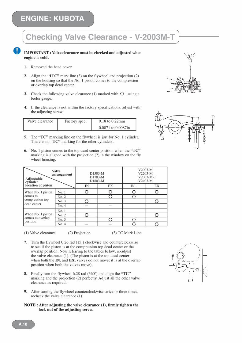
IMPORTANT : Valve clearance must be checked and adjusted when engine is cold.
1. Removed the head cover.
2. Align the “1TC” mark line (3) on the flywheel and projection (2) on the housing so that the No. 1 piston comes to the compression or overlap top dead center.
3. Check the following valve clearance (1) marked with ‘ ‘ using a feeler gauge.
4. If the clearance is not within the factory specifications, adjust with the adjusting screw.
Valve clearance Factory spec. 0.18 to 0.22mm 0.0071 to 0.0087in
5. The “TC” marking line on the flywheel is just for No. 1 cylinder. There is no “TC” marking for the other cylinders.
6. No. 1 piston comes to the top dead center position when the “TC” marking is aligned with the projection (2) in the window on the fly wheel-housing.
(1) Valve clearance (2) Projection (3) TC Mark Line
7. Turn the flywheel 0.26 rad (15˚) clockwise and counterclockwise to see if the piston is at the compression top dead center or the overlap position. Now referring to the tables below, re-adjust the valve clearance (1). (The piston is at the top dead center when both the IN. and EX. valves do not move; it is at the overlap position when both the valves move).
8. Finally turn the flywheel 6.28 rad (360˚) and align the “TC” marking and the projection (2) perfectly. Adjust all the other valve clearance as required.
9. After turning the flywheel counterclockwise twice or three times, recheck the valve clearance (1).
NOTE : After adjusting the valve clearance (1), firmly tighten the lock nut of the adjusting screw.
V2003-M D1503-M V2203-M D1703-M V2003-M-T D1803-M V2403-M
Valvearrangement
Adjustablecylinderlocation of piston IN. EX. IN. EX.
When No. 1 pistoncomes tocompression topdead center
When No. 1 pistoncomes to overlapposition
No. 1No. 2No. 3No. 4No. 1No. 2No. 3No. 4
!
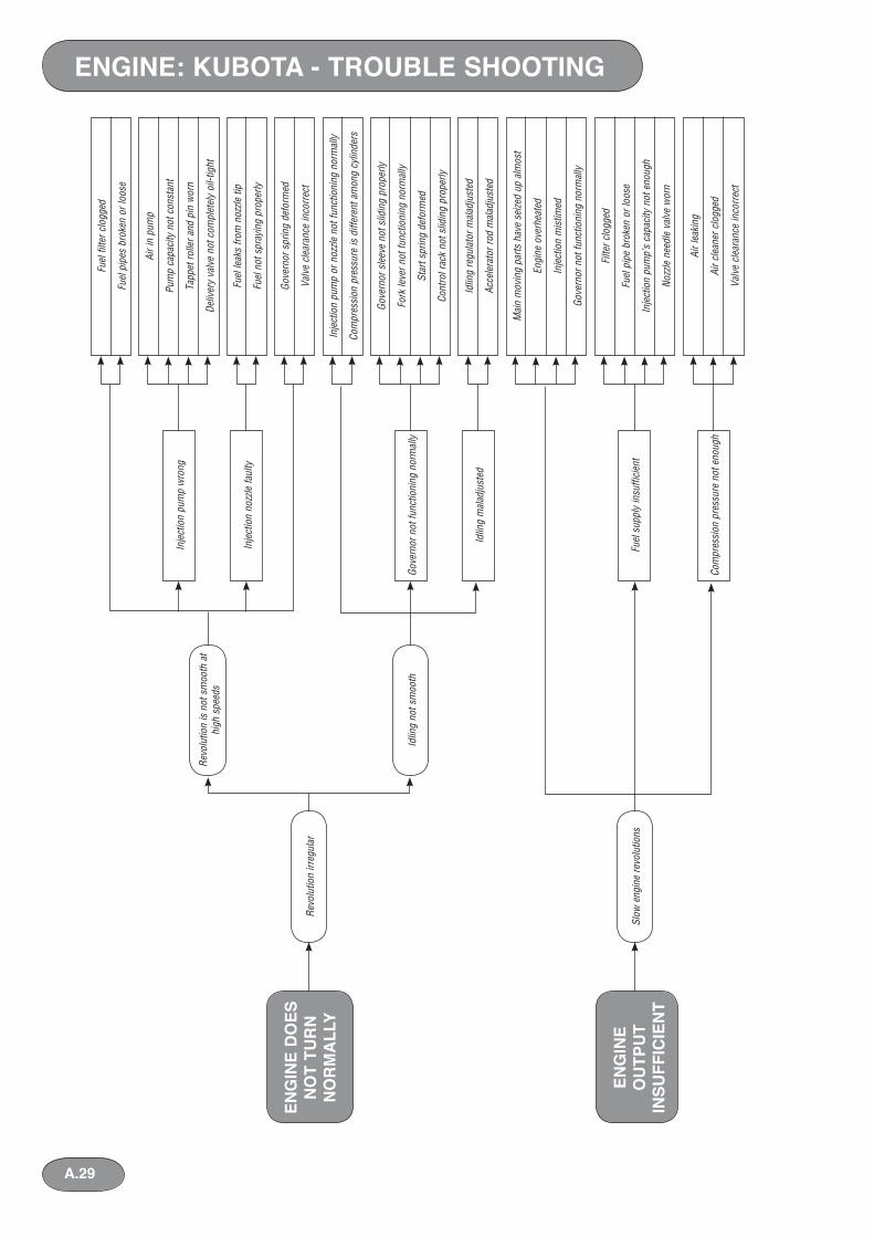
Trouble Shooting
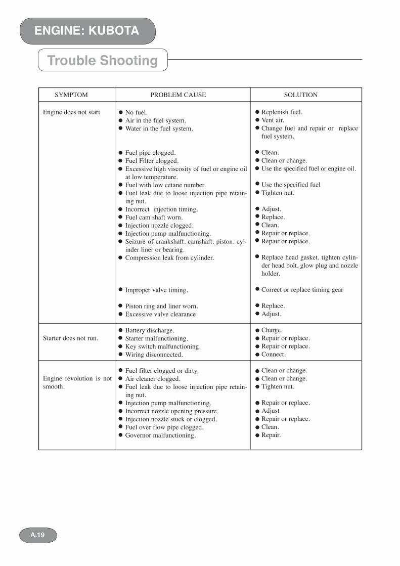
No fuel.Air in the fuel system.Water in the fuel system.
Fuel pipe clogged.Fuel Filter clogged.Excessive high viscosity of fuel or engine oil at low temperature.Fuel with low cetane number.Fuel leak due to loose injection pipe retain-ing nut.Incorrect injection timing.Fuel cam shaft worn.Injection nozzle clogged.Injection pump malfunctioning.Seizure of crankshaft, camshaft, piston, cyl-inder liner or bearing.Compression leak from cylinder.
Improper valve timing.
Piston ring and liner worn.Excessive valve clearance.
Battery discharge.Starter malfunctioning.Key switch malfunctioning.Wiring disconnected.
Fuel filter clogged or dirty.Air cleaner clogged.Fuel leak due to loose injection pipe retain-ing nut.Injection pump malfunctioning.Incorrect nozzle opening pressure.Injection nozzle stuck or clogged.Fuel over flow pipe clogged.Governor malfunctioning.
SYMPTOM PROBLEM CAUSE SOLUTION
Engine does not start
Starter does not run.
Engine revolution is not smooth.
Replenish fuel.Vent air.Change fuel and repair or replace fuel system.
Clean.Clean or change.Use the specified fuel or engine oil.
Use the specified fuelTighten nut.
Adjust.Replace.Clean.Repair or replace.Repair or replace.
Replace head gasket, tighten cylin-der head bolt, glow plug and nozzle holder.
Correct or replace timing gear
Replace.Adjust.
Charge.Repair or replace.Repair or replace.Connect.
Clean or change.Clean or change.Tighten nut.
Repair or replace. AdjustRepair or replace. Clean.Repair.
ENGINE: KUBOTA
A.19
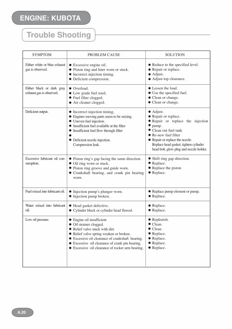
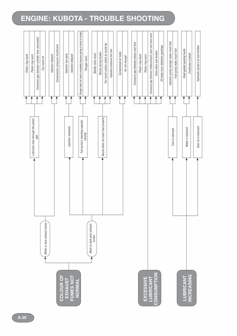
Trouble Shooting
Reduce to the specified level.Repair or replace.Adjust.Adjust top clearance.
Lessen the load.Use the specified fuel.Clean or change.Clean or change.
Adjust.Repair or replace.Repair or replace the injection pump.Clean out fuel tankRe-new fuel filterRepair or replace the nozzle.Replace head gasket, tighten cylinder head bolt, glow plug and nozzle holder.
Shift ring gap direction.Replace.Replace the pistonReplace.
Replace pump element or pump.Replace.
Replace. Replace.
Replenish.Clean.Clean.Replace.Replace.Replace.Replace.
Excessive engine oil.Piston ring and liner worn or stuck.Incorrect injection timing.Deficient compression.
Overload.Low grade fuel used.Fuel filter clogged.Air cleaner clogged.
Incorrect injection timing.Engines moving parts seem to be seizing.Uneven fuel injection.Insufficient fuel available at the filterInsufficient fuel flow through filter
Deficient nozzle injection.Compression leak.
Piston ring’s gap facing the same direction.Oil ring worn or stuck.Piston ring groove and guide worn.Crankshaft bearing, and crank pin bearing worn.
Injection pump’s plunger worn.Injection pump broken.
Head gasket defective.Cylinder block or cylinder head flawed.
Engine oil insufficientOil strainer clogged.Relief valve stuck with dirt.Relief valve spring weaken or broken.Excessive oil clearance of crankshaft bearing.Excessive oil clearance of crank pin bearing.Excessive oil clearance of rocker arm bearing.
SYMPTOM PROBLEM CAUSE SOLUTION
Either white or blue exhaust gas is observed.
Either black or dark gray exhaust gas is observed.
Deficient output.
Excessive lubricant oil con-sumption.
Fuel mixed into lubricant oil.
Water mixed into lubricant oil.
Low oil pressure.
ENGINE: KUBOTA
A.20
Trouble Shooting
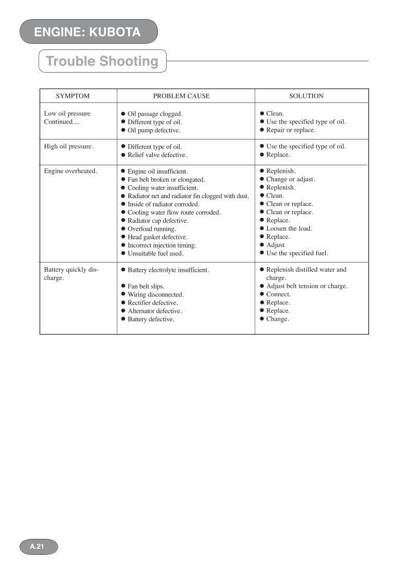
Clean.Use the specified type of oil.Repair or replace.
Use the specified type of oil.Replace.
Replenish.Change or adjust.Replenish.Clean.Clean or replace.Clean or replace.Replace.Loosen the load.Replace.AdjustUse the specified fuel.
Replenish distilled water and charge.Adjust belt tension or charge.Connect.Replace.Replace.Change.
Oil passage clogged.Different type of oil.Oil pump defective.
Different type of oil.Relief valve defective.
Engine oil insufficient.Fan belt broken or elongated.Cooling water insufficient.Radiator net and radiator fin clogged with dust.Inside of radiator corroded.Cooling water flow route corroded.Radiator cap defective.Overload running.Head gasket defective.Incorrect injection timing.Unsuitable fuel used.
Battery electrolyte insufficient.
Fan belt slips.Wiring disconnected.Rectifier defective.Alternator defective.Battery defective.
SYMPTOM PROBLEM CAUSE SOLUTION
Low oil pressureContinued....
High oil pressure.
Engine overheated.
Battery quickly dis-charge.
A.21
ENGINE: KUBOTA
ENGINE: KUBOTA
A.22
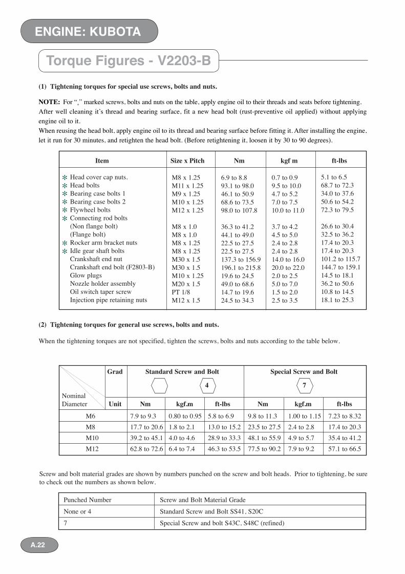
Torque Figures - V2203-B(1) Tightening torques for special use screws, bolts and nuts.
NOTE: For “*” marked screws, bolts and nuts on the table, apply engine oil to their threads and seats before tightening.After well cleaning it’s thread and bearing surface, fit a new head bolt (rust-preventive oil applied) without applying engine oil to it.When reusing the head bolt, apply engine oil to its thread and bearing surface before fitting it. After installing the engine, let it run for 30 minutes, and retighten the head bolt. (Before retightening it, loosen it by 30 to 90 degrees).
(2) Tightening torques for general use screws, bolts and nuts.
When the tightening torques are not specified, tighten the screws, bolts and nuts according to the table below.
Screw and bolt material grades are shown by numbers punched on the screw and bolt heads. Prior to tightening, be sure to check out the numbers as shown below.
Item Size x Pitch Nm kgf m ft-lbs
Head cover cap nuts. Head bolts Bearing case bolts 1 Bearing case bolts 2 Flywheel bolts Connecting rod bolts (Non flange bolt) (Flange bolt) Rocker arm bracket nuts Idle gear shaft bolts Crankshaft end nut Crankshaft end bolt (F2803-B) Glow plugs Nozzle holder assembly Oil switch taper screw Injection pipe retaining nuts
M8 x 1.25M11 x 1.25M9 x 1.25M10 x 1.25M12 x 1.25
M8 x 1.0M8 x 1.0M8 x 1.25M8 x 1.25M30 x 1.5M30 x 1.5M10 x 1.25M20 x 1.5PT 1/8M12 x 1.5
6.9 to 8.893.1 to 98.046.1 to 50.968.6 to 73.598.0 to 107.8
36.3 to 41.244.1 to 49.022.5 to 27.522.5 to 27.5137.3 to 156.9196.1 to 215.819.6 to 24.549.0 to 68.614.7 to 19.624.5 to 34.3
0.7 to 0.99.5 to 10.04.7 to 5.27.0 to 7.510.0 to 11.0
3.7 to 4.24.5 to 5.02.4 to 2.82.4 to 2.814.0 to 16.020.0 to 22.02.0 to 2.55.0 to 7.01.5 to 2.02.5 to 3.5
5.1 to 6.568.7 to 72.334.0 to 37.650.6 to 54.272.3 to 79.5
26.6 to 30.432.5 to 36.217.4 to 20.317.4 to 20.3101.2 to 115.7144.7 to 159.114.5 to 18.136.2 to 50.610.8 to 14.518.1 to 25.3
*
Grad Standard Screw and Bolt Special Screw and Bolt
4 7Nominal Diameter Unit Nm kgf.m ft-lbs Nm kgf.m ft-lbs
M6 7.9 to 9.3 0.80 to 0.95 5.8 to 6.9 9.8 to 11.3 1.00 to 1.15 7.23 to 8.32M8 17.7 to 20.6 1.8 to 2.1 13.0 to 15.2 23.5 to 27.5 2.4 to 2.8 17.4 to 20.3M10 39.2 to 45.1 4.0 to 4.6 28.9 to 33.3 48.1 to 55.9 4.9 to 5.7 35.4 to 41.2M12 62.8 to 72.6 6.4 to 7.4 46.3 to 53.5 77.5 to 90.2 7.9 to 9.2 57.1 to 66.5
Punched Number Screw and Bolt Material Grade
None or 4 Standard Screw and Bolt SS41, S20C
7 Special Screw and bolt S43C, S48C (refined)
***
**
**
A.23
ENGINE: KUBOTA
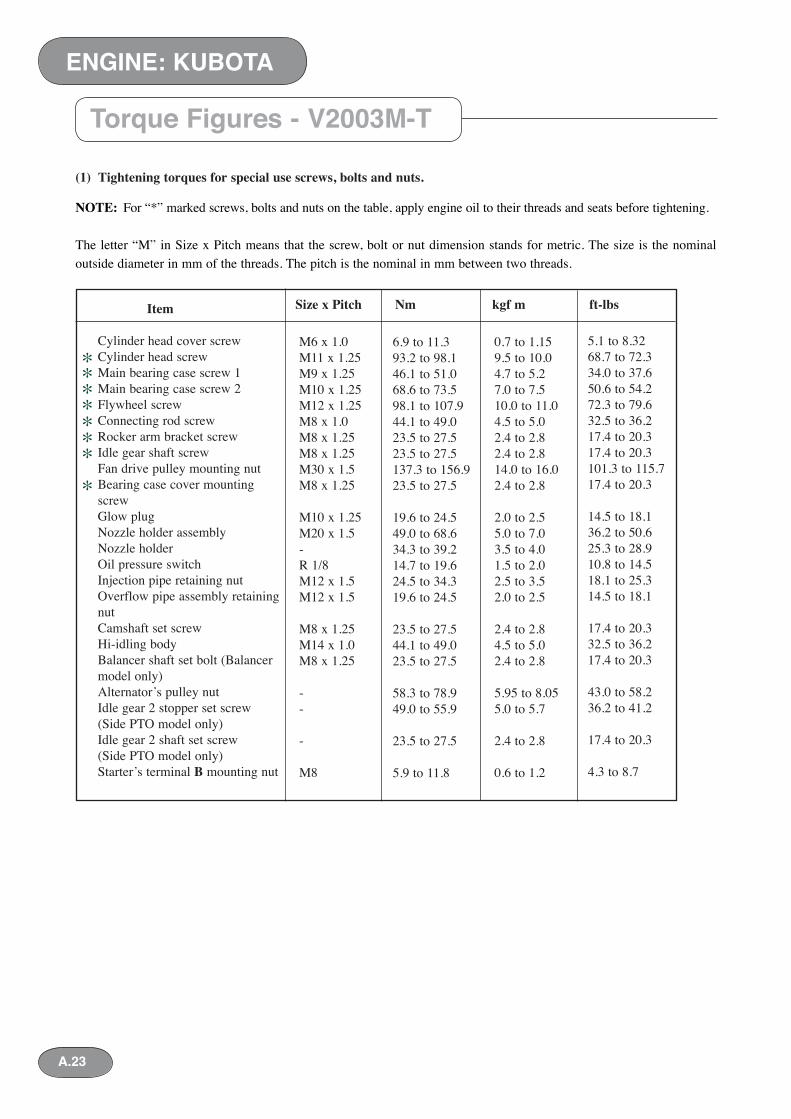
Torque Figures - V2003M-T
(1) Tightening torques for special use screws, bolts and nuts.
NOTE: For “*” marked screws, bolts and nuts on the table, apply engine oil to their threads and seats before tightening.
The letter “M” in Size x Pitch means that the screw, bolt or nut dimension stands for metric. The size is the nominal outside diameter in mm of the threads. The pitch is the nominal in mm between two threads.
Item
Cylinder head cover screw Cylinder head screw Main bearing case screw 1 Main bearing case screw 2 Flywheel screw Connecting rod screw Rocker arm bracket screw Idle gear shaft screw Fan drive pulley mounting nut Bearing case cover mounting screw Glow plug Nozzle holder assembly Nozzle holder Oil pressure switch Injection pipe retaining nut Overflow pipe assembly retaining nut Camshaft set screw Hi-idling body Balancer shaft set bolt (Balancer model only) Alternator’s pulley nut Idle gear 2 stopper set screw (Side PTO model only) Idle gear 2 shaft set screw (Side PTO model only) Starter’s terminal B mounting nut
M6 x 1.0 M11 x 1.25M9 x 1.25M10 x 1.25M12 x 1.25M8 x 1.0M8 x 1.25M8 x 1.25M30 x 1.5M8 x 1.25
M10 x 1.25M20 x 1.5-R 1/8M12 x 1.5M12 x 1.5
M8 x 1.25M14 x 1.0M8 x 1.25
--
-
M8
6.9 to 11.393.2 to 98.146.1 to 51.068.6 to 73.598.1 to 107.944.1 to 49.023.5 to 27.523.5 to 27.5137.3 to 156.923.5 to 27.5
19.6 to 24.549.0 to 68.634.3 to 39.214.7 to 19.624.5 to 34.319.6 to 24.5
23.5 to 27.544.1 to 49.023.5 to 27.5
58.3 to 78.949.0 to 55.9
23.5 to 27.5
5.9 to 11.8
0.7 to 1.159.5 to 10.04.7 to 5.27.0 to 7.510.0 to 11.04.5 to 5.02.4 to 2.82.4 to 2.814.0 to 16.02.4 to 2.8
2.0 to 2.55.0 to 7.03.5 to 4.01.5 to 2.02.5 to 3.52.0 to 2.5
2.4 to 2.84.5 to 5.02.4 to 2.8
5.95 to 8.055.0 to 5.7
2.4 to 2.8
0.6 to 1.2
5.1 to 8.3268.7 to 72.334.0 to 37.650.6 to 54.272.3 to 79.632.5 to 36.217.4 to 20.317.4 to 20.3101.3 to 115.717.4 to 20.3
14.5 to 18.136.2 to 50.625.3 to 28.910.8 to 14.518.1 to 25.314.5 to 18.1
17.4 to 20.332.5 to 36.217.4 to 20.3
43.0 to 58.236.2 to 41.2
17.4 to 20.3
4.3 to 8.7
***
**
*
Size x Pitch Nm kgf m ft-lbs
**
ENGINE: KUBOTA
A.24
Torque Figures - V2003M-T
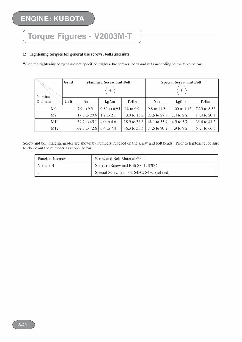
(2) Tightening torques for general use screws, bolts and nuts.
When the tightening torques are not specified, tighten the screws, bolts and nuts according to the table below.
Screw and bolt material grades are shown by numbers punched on the screw and bolt heads. Prior to tightening, be sure to check out the numbers as shown below.
Grad Standard Screw and Bolt Special Screw and Bolt
4 7Nominal Diameter Unit Nm kgf.m ft-lbs Nm kgf.m ft-lbs
M6 7.9 to 9.3 0.80 to 0.95 5.8 to 6.9 9.8 to 11.3 1.00 to 1.15 7.23 to 8.32M8 17.7 to 20.6 1.8 to 2.1 13.0 to 15.2 23.5 to 27.5 2.4 to 2.8 17.4 to 20.3M10 39.2 to 45.1 4.0 to 4.6 28.9 to 33.3 48.1 to 55.9 4.9 to 5.7 35.4 to 41.2M12 62.8 to 72.6 6.4 to 7.4 46.3 to 53.5 77.5 to 90.2 7.9 to 9.2 57.1 to 66.5
Punched Number Screw and Bolt Material Grade
None or 4 Standard Screw and Bolt SS41, S20C
7 Special Screw and bolt S43C, S48C (refined)
A.25
ENGINE: KUBOTA
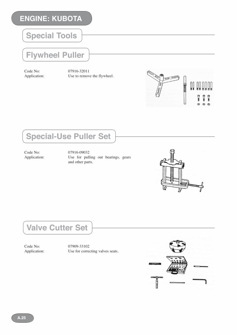
Code No: 07916-32011Application: Use to remove the flywheel.
Code No: 07916-09032Application: Use for pulling out bearings, gears and other parts.
Code No: 07909-33102Application: Use for correcting valves seats.
Flywheel Puller
Special-Use Puller Set
Valve Cutter Set
Special Tools
ENGINE: KUBOTA
A.26
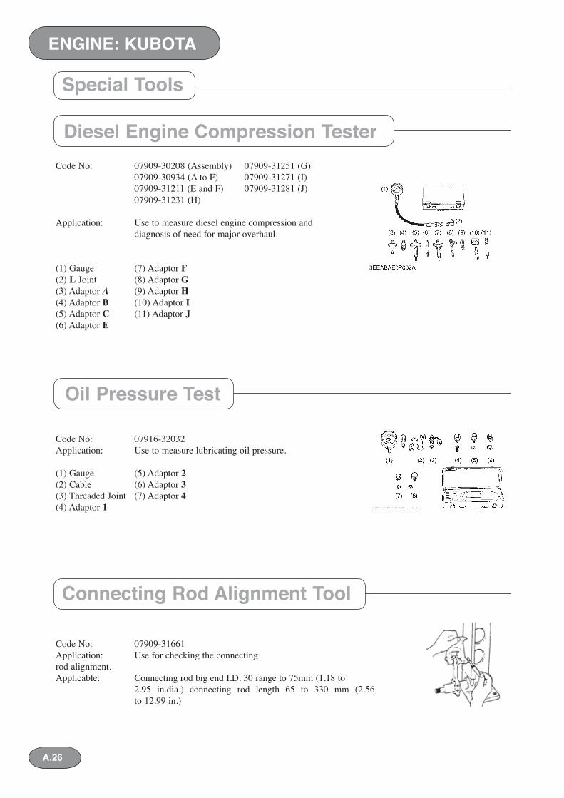
Code No: 07909-30208 (Assembly) 07909-31251 (G) 07909-30934 (A to F) 07909-31271 (I) 07909-31211 (E and F) 07909-31281 (J) 07909-31231 (H)
Application: Use to measure diesel engine compression and diagnosis of need for major overhaul.
(1) Gauge (7) Adaptor F(2) L Joint (8) Adaptor G(3) Adaptor A (9) Adaptor H(4) Adaptor B (10) Adaptor I(5) Adaptor C (11) Adaptor J(6) Adaptor E
Code No: 07916-32032Application: Use to measure lubricating oil pressure.
(1) Gauge (5) Adaptor 2(2) Cable (6) Adaptor 3(3) Threaded Joint (7) Adaptor 4(4) Adaptor 1
Code No: 07909-31661Application: Use for checking the connecting rod alignment.Applicable: Connecting rod big end I.D. 30 range to 75mm (1.18 to 2.95 in.dia.) connecting rod length 65 to 330 mm (2.56 to 12.99 in.)
Diesel Engine Compression Tester
Oil Pressure Test
Connecting Rod Alignment Tool
Special Tools
A.27
ENGINE: KUBOTA
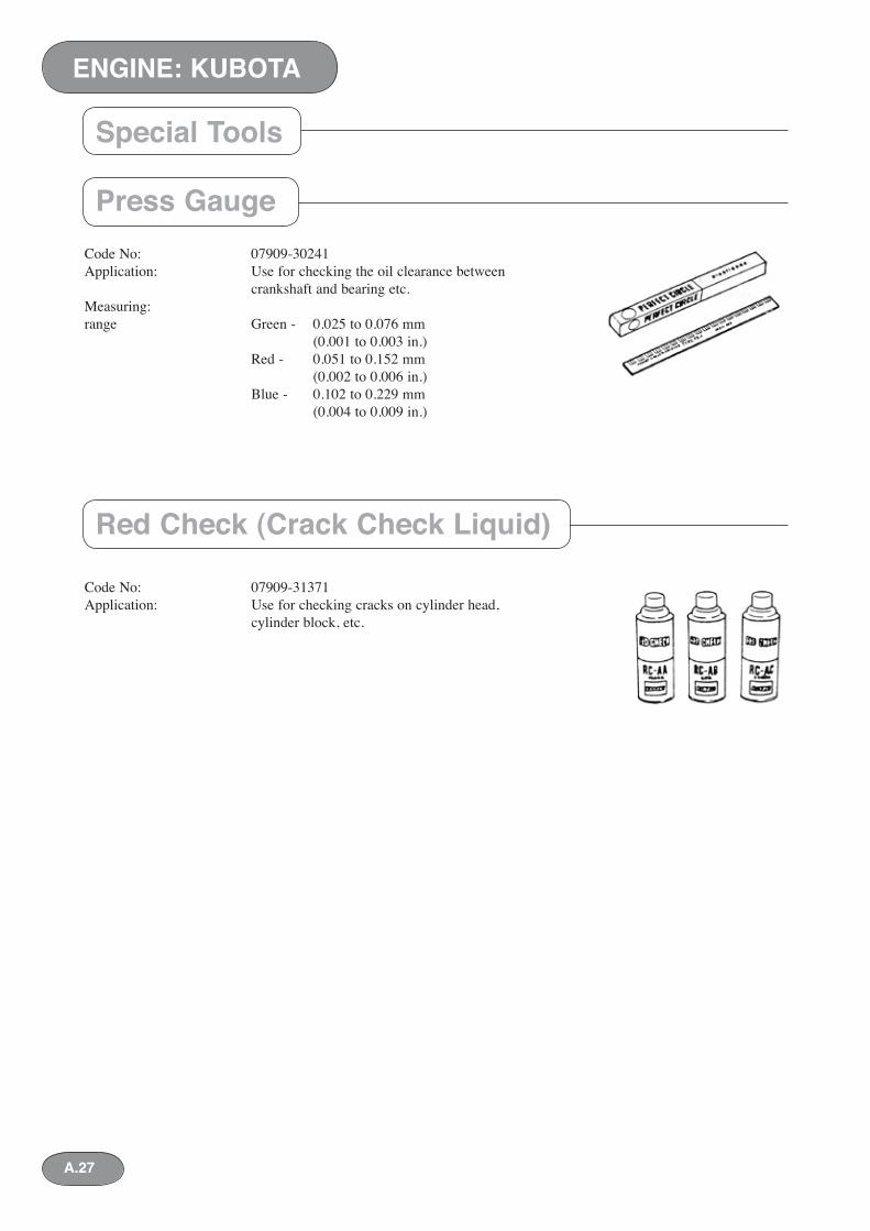
Code No: 07909-30241Application: Use for checking the oil clearance between crankshaft and bearing etc.Measuring: range Green - 0.025 to 0.076 mm (0.001 to 0.003 in.) Red - 0.051 to 0.152 mm (0.002 to 0.006 in.) Blue - 0.102 to 0.229 mm (0.004 to 0.009 in.)
Code No: 07909-31371Application: Use for checking cracks on cylinder head, cylinder block, etc.
Press Gauge
Red Check (Crack Check Liquid)
Special Tools
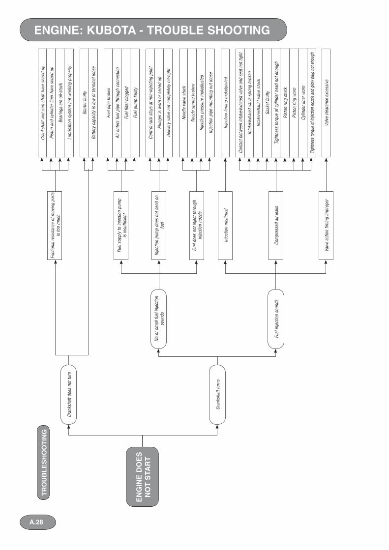
ENGINE: KUBOTA - TROUBLE SHOOTINGTR
OU
BLE
SHO
OTI
NG
Cran
ksha
ft do
es n
ot tu
rn
No o
r sm
all f
uel i
njec
tion
soun
ds
Fric
tiona
l res
ista
nce
of m
ovin
g pa
rts
is to
o m
uch
Cran
ksha
ft an
d ca
m s
haft
have
sei
zed
up
Pist
on a
nd c
ylin
der l
iner
hav
e se
ized
up
Bear
ings
are
oil-
stuc
k
Lubr
icat
ion
syst
em n
ot w
orki
ng p
rope
rly
Star
ter f
aulty
Batte
ry c
apac
ity is
low
or t
erm
inal
loos
e
Fuel
pip
e br
oken
Air e
nter
s fu
el p
ipe
thro
ugh
conn
ectio
n
Fuel
filte
r clo
gged
Fuel
pum
p fa
ulty
Cont
rol r
ack
stay
s at
non
-inje
ctin
g po
int
Plun
ger i
s w
orn
or s
eize
d up
Deliv
ery
valv
e no
t com
plet
ely
oil-t
ight
Need
le v
alve
stu
ck
Nozz
le s
prin
g br
oken
Inje
ctio
n pr
essu
re m
alad
just
ed
Inje
ctio
n pi
pe m
ount
ing
nut l
oose
Inje
ctio
n tim
ing
mal
adju
sted
Cont
act b
etw
een
inta
ke/e
xhau
st v
alve
and
sea
t not
tigh
t
Inta
ke/e
xhau
st v
alve
spr
ing
brok
en
Inta
ke/e
xhau
st v
alve
stu
ck
Gask
et fa
ulty
Tigh
tnes
s to
rque
of c
ylin
der h
ead
not e
noug
h
Pist
on ri
ng s
tuck
Pist
on ri
ng w
orn
Cylin
der l
iner
wor
n
Tigh
tnes
s to
rque
of i
njec
tion
nozz
le a
nd g
low
plu
g no
t eno
ugh
Valv
e cl
eara
nce
exce
ssiv
e
Fuel
sup
ply
to in
ject
ion
pum
p
is in
suffi
cien
t
Inje
ctio
n m
istim
ed
Fuel
inje
ctio
n so
unds
Cran
ksha
ft tu
rns
Com
pres
sed
air l
eaks
Valv
e ac
tion
timin
g im
prop
er
Inje
ctio
n pu
mp
does
not
sen
d on
fu
el
Fuel
doe
s no
t inj
ect t
hrou
gh
inje
ctio
n no
zzle
ENG
INE
DO
ES
NO
T ST
AR
T
A.28
Air i
n pu
mp
Pum
p ca
paci
ty n
ot c
onst
ant
Tapp
et ro
ller a
nd p
in w
orn
Deliv
ery
valv
e no
t com
plet
ely
oil-t
ight
Fuel
filte
r clo
gged
Fuel
pip
es b
roke
n or
loos
e
Air l
eaki
ng
Air c
lean
er c
logg
ed
Valv
e cl
eara
nce
inco
rrec
t
Gove
rnor
sle
eve
not s
lidin
g pr
oper
ly
Fork
leve
r not
func
tioni
ng n
orm
ally
Star
t spr
ing
defo
rmed
Cont
rol r
ack
not s
lidin
g pr
oper
ly
Revo
lutio
n is
not
sm
ooth
at
high
spe
eds
Slow
eng
ine
revo
lutio
ns
Mai
n m
ovin
g pa
rts h
ave
seize
d up
alm
ost
Engi
ne o
verh
eate
d
Inje
ctio
n m
istim
ed
Gove
rnor
not
func
tioni
ng n
orm
ally
Filte
r clo
gged
Fuel
pip
e br
oken
or l
oose
Inje
ctio
n pu
mp’
s ca
paci
ty n
ot e
noug
h
Nozz
le n
eedl
e va
lve
wor
n
Fuel
leak
s fro
m n
ozzle
tip
Fuel
not
spr
ayin
g pr
oper
ly
Gove
rnor
spr
ing
defo
rmed
Valv
e cl
eara
nce
inco
rrec
t
Inje
ctio
n pu
mp
or n
ozzle
not
func
tioni
ng n
orm
ally
Com
pres
sion
pre
ssur
e is
diff
eren
t am
ong
cylin
ders
Idlin
g re
gula
tor m
alad
just
ed
Acce
lera
tor r
od m
alad
just
ed
ENG
INE
DO
ES
NO
T TU
RN
N
OR
MA
LLY
ENG
INE
OU
TPU
T IN
SUFF
ICIE
NT
Idlin
g m
alad
just
ed
Fuel
sup
ply
insu
ffici
ent
Com
pres
sion
pre
ssur
e no
t eno
ugh
Gove
rnor
not
func
tioni
ng n
orm
ally
Inje
ctio
n pu
mp
wro
ng
Inje
ctio
n no
zzle
faul
ty
Idlin
g no
t sm
ooth
Revo
lutio
n irr
egul
ar
ENGINE: KUBOTA - TROUBLE SHOOTING
A.29
A.30
Pist
on ri
ng s
tuck
Pist
on ri
ng w
orn
Exce
ssiv
e ga
p be
twee
n cy
linde
r lin
er a
nd p
isto
n
Too
muc
h oi
l
Need
le v
alve
stu
ck
Nozz
le s
prin
g br
oken
Too
muc
h ca
rbon
stic
ks to
noz
zle ti
p
Inje
ctio
n pr
essu
re to
o lo
w
Inje
ctio
n de
laye
d
Com
pres
sion
pre
ssur
e in
suffi
cien
t
Inje
ctio
n to
o ea
rly
Inje
ctio
n de
laye
d
Plun
ger d
oes n
ot re
turn
com
plet
ely b
ecau
se sp
ring
is st
uck o
r bro
ken
Plun
ger w
orn
Com
pres
sed
air l
eaks
Air n
ot e
noug
h
Inje
ctio
n pu
mp
plun
ger l
eaks
muc
h fu
el
Fuel
pum
p le
aks
muc
h fu
el
Head
gas
ket p
acki
ng fa
ulty
Cran
kcas
e cr
acke
d
CO
LOU
R O
F EX
HA
UST
FU
MES
NO
T N
OR
MA
L
EXC
ESSI
VE
LUB
RIC
AN
T C
ON
SUM
PTIO
N
LUB
RIC
AN
T IN
CR
EASI
NG
Fuel
in lu
bric
ant
Wat
er in
lubr
ican
t
Fuel
pum
p’s
inje
ctin
g ca
paci
ty
vary
ing
Nozz
le d
oes
not i
njec
t fue
l pro
perly
Lubr
ican
t ris
es th
roug
h th
e pi
ston
ga
p
Inje
ctio
n m
istim
ed
Blac
k or
dar
k gr
ey e
xhau
st
fum
es
Whi
te o
r blu
e ex
haus
t fum
es
Exce
ssiv
e ga
p be
twee
n pi
ston
and
line
r
Pist
on ri
ng s
tuck
Pist
on ri
ng w
orn
Exce
ssiv
e ga
p be
twee
n in
take
/exh
aust
val
ve a
nd v
alve
ste
m
Valv
e st
em s
eal b
roke
n
Oil l
eaks
from
def
ectiv
e pa
ckin
gs
Hydr
aulic
pum
p’s
oil s
eal b
roke
nGe
ar o
il in
lubr
ican
t
ENGINE: KUBOTA - TROUBLE SHOOTING