section bending machine - prada nargesa. de garrigàs a sant miquel s/n 17476 palau de sta. eulalia...
TRANSCRIPT
INSTRUCTIONS BOOK
PRADA NARGESA, S.L Ctra. de Garrigàs a Sant Miquel s/n
17476 PALAU DE STA. EULALIA (GIRONA) SPAIN
Tel. 972 568085 - Fax 972 568320
www.nargesa.com - [email protected]
SECTION BENDING MACHINE
MC650
Thanks for choosing our machines
www.nargesa.com
MC650 SECTION BENDING MACHINE INSTRUCTION BOOK 2
INDEX
1. MACHINE DETAILS ................................................................................................................
1.1. Machine identification details ......................................................................................
1.2. Dimensions …..............................................................................................................
1.3. Description of the machine ..........................................................................................
1.4. Machine part identification ..........................................................................................
1.5. General characteristics ……........................................................................................
1.6. Description of the guards ……….................................................................................
2. TRANSPORT AND STORAGE ………….................................................................................
2.1. Transport ..................................................................................................................
2.2. Storage conditions ……………….................................................................................
3. MAINTENANCE ….................................................................................................................
3.1. General maintenance ...............................................................................................
4. INSTALLATION AND START UP ………….............................................................................
4.1. Positioning the machine ..............................................................................................
4.2. Dimensions and work area ……..................................................................................
4.3. External permisible conditions ….................................................................................
4.4. Instructions for connecting to the power supply ..........................................................
5. INSTRUCTIONS FOR USE .....................................................................................................
5.1. Bending principles ……................................................................................................
5.2. Assembly of the rollers ................................................................................................
5.3. Instruction manual …...................................................................................................
5.3.1. Pilot lights …………………….…………………………………………………….
5.3.2. Main buttons …………….…………………………………………………………
5.3.3. Roller position controllers …………………………………………………………
5.3.4. Direction of rotation of rollers ….…………………………………………………
5.4. Working position …………………………………………………………………………….
6. WARNINGS …….....................................................................................................................
6.1. Residual hazards ….....................................................................................................
6.2. Counter-productive methods .......................................................................................
6.3. Other recommendations ..............................................................................................
7. ASSEMBLY OF THE ROLLERS ……......................................................................................
7.1. Bending capacity .........................................................................................................
8. OPTIONAL ACCESSORIES …................................................................................................
TECHNICAL ANNEX
3
3
3
3
4
5
6
7
7
7
8
8
9
9
9
9
10
13
13
13
14
15
15
16
16
17
19
19
19
19
20
21
22
MC650 SECTION BENDING MACHINE INSTRUCTION BOOK 3
1. MACHINE DETAILS
1.1. Machine identification details
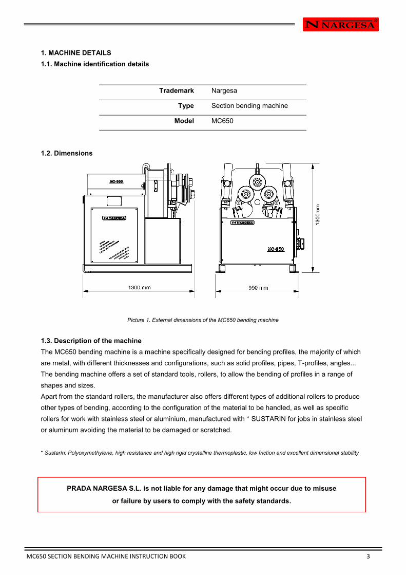
1.2. Dimensions
Picture 1. External dimensions of the MC650 bending machine
1.3. Description of the machine
The MC650 bending machine is a machine specifically designed for bending profiles, the majority of which
are metal, with different thicknesses and configurations, such as solid profiles, pipes, T-profiles, angles...
The bending machine offers a set of standard tools, rollers, to allow the bending of profiles in a range of
shapes and sizes.
Apart from the standard rollers, the manufacturer also offers different types of additional rollers to produce
other types of bending, according to the configuration of the material to be handled, as well as specific
rollers for work with stainless steel or aluminium, manufactured with * SUSTARIN for jobs in stainless steel
or aluminum avoiding the material to be damaged or scratched.
* Sustarín: Polyoxymethylene, high resistance and high rigid crystalline thermoplastic, low friction and excellent dimensional stability
PRADA NARGESA S.L. is not liable for any damage that might occur due to misuse
or failure by users to comply with the safety standards.
Trademark Nargesa
Type Section bending machine
Model MC650
MC650 SECTION BENDING MACHINE INSTRUCTION BOOK 4
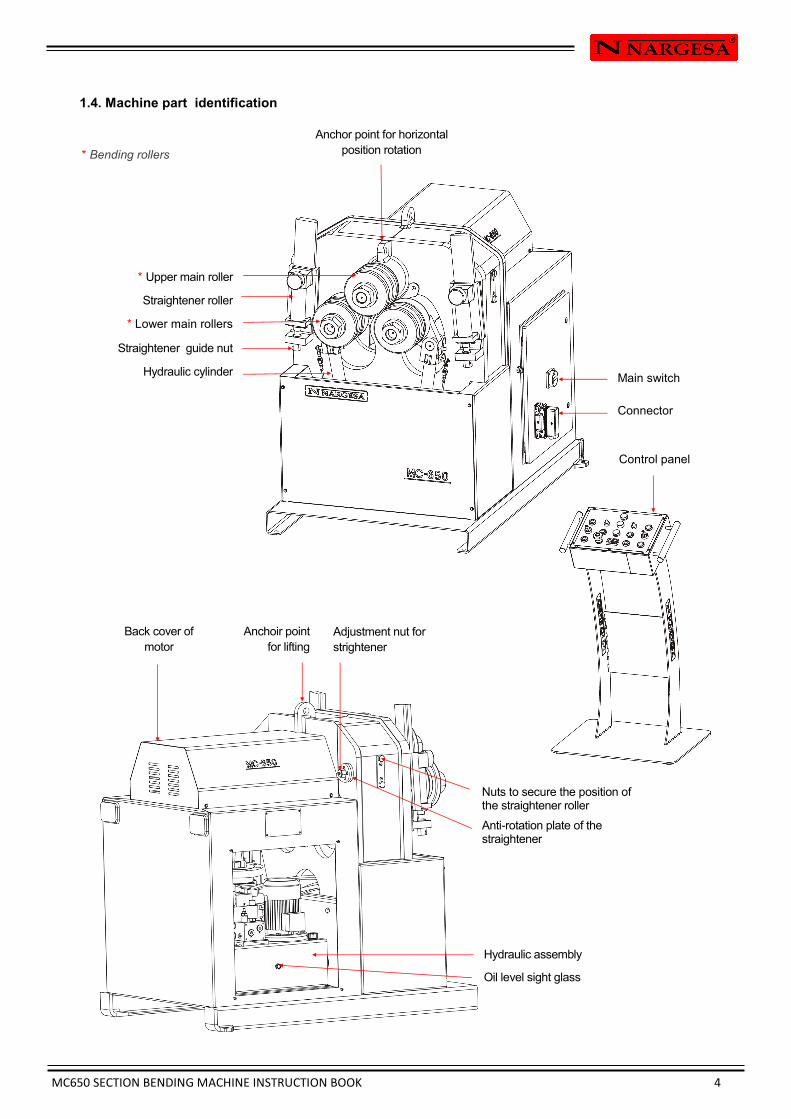
1.4. Machine part identification
* Upper main roller
Straightener roller
* Lower main rollers
Straightener guide nut
Hydraulic cylinder
Control panel
* Bending rollers
Nuts to secure the position of the straightener roller
Anti-rotation plate of the straightener
Main switch
Connector
Anchoir point
for lifting
Anchor point for horizontal
position rotation
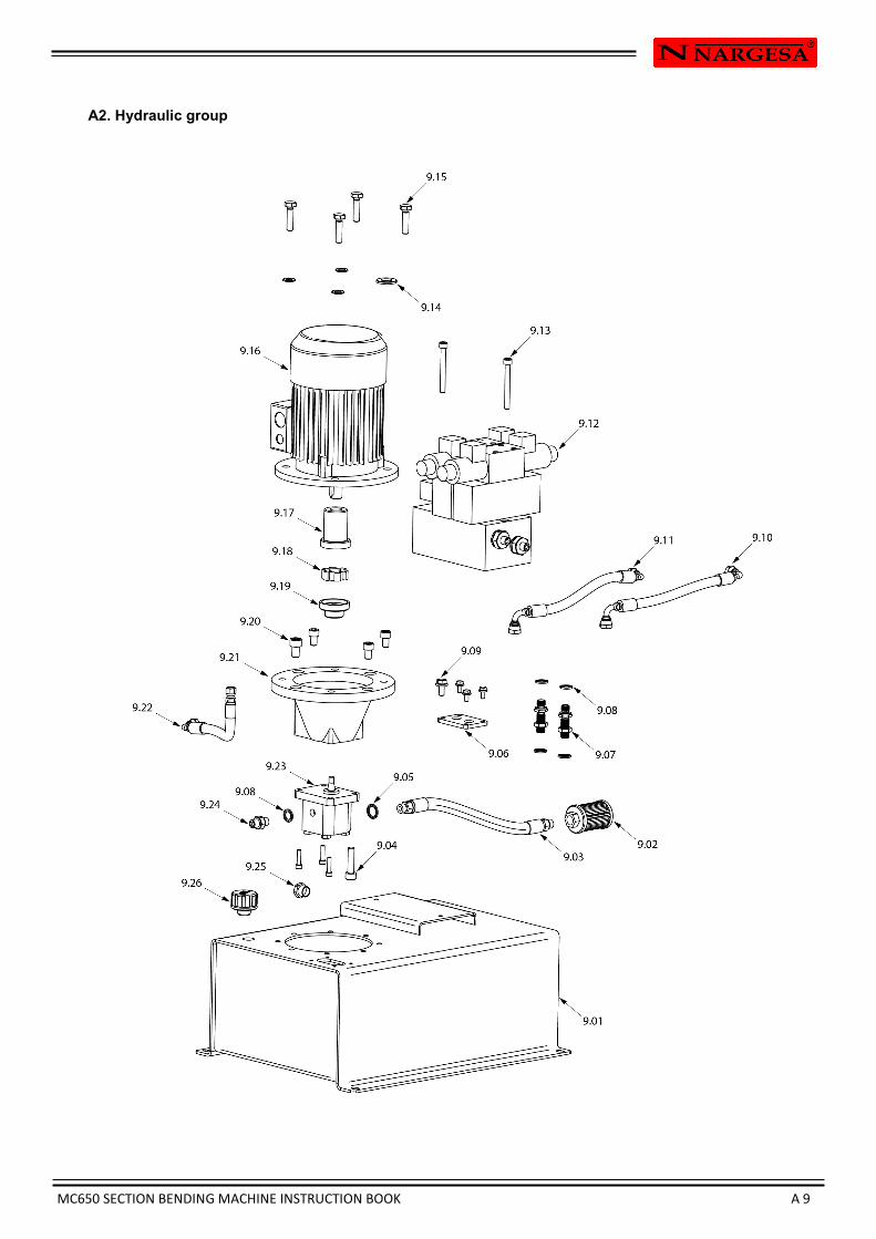
Hydraulic assembly
Oil level sight glass
Adjustment nut for
strightener Back cover of
motor
MC650 SECTION BENDING MACHINE INSTRUCTION BOOK 5
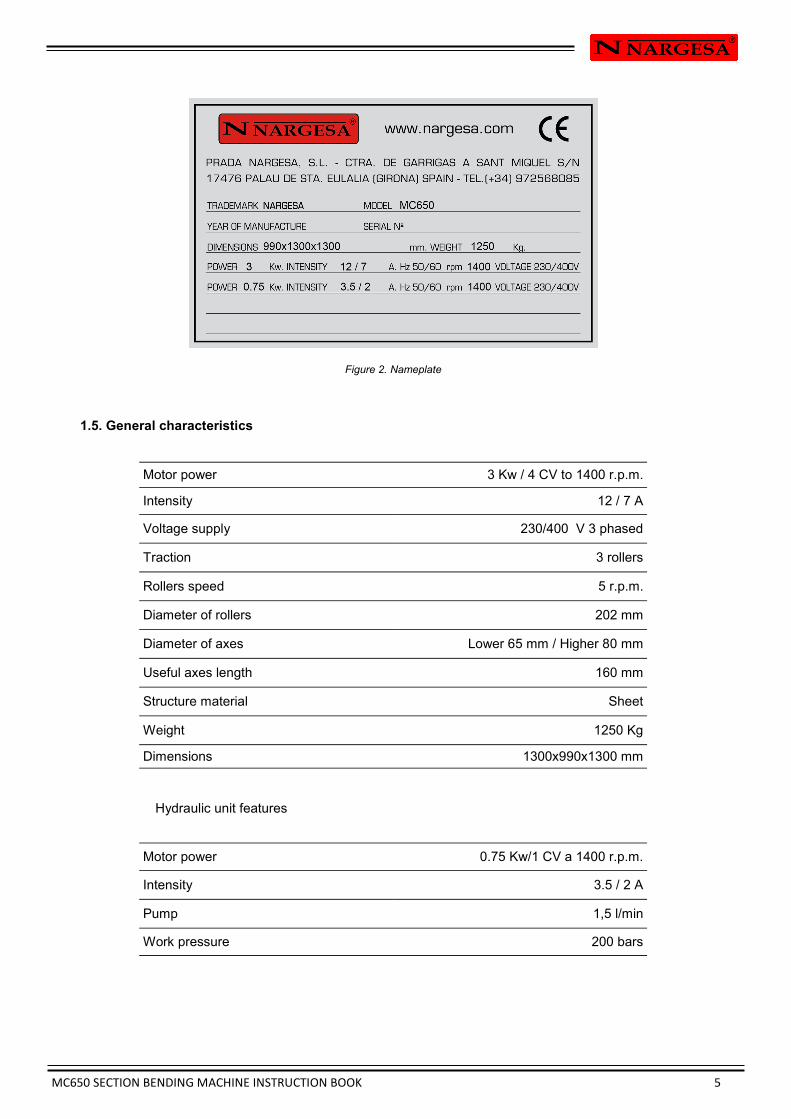
Figure 2. Nameplate
1.5. General characteristics
Hydraulic unit features
Motor power 3 Kw / 4 CV to 1400 r.p.m.
Intensity 12 / 7 A
Voltage supply 230/400 V 3 phased
Traction 3 rollers
Rollers speed 5 r.p.m.
Diameter of rollers 202 mm
Diameter of axes Lower 65 mm / Higher 80 mm
Useful axes length 160 mm
Structure material Sheet
Weight 1250 Kg
Dimensions 1300x990x1300 mm
Motor power 0.75 Kw/1 CV a 1400 r.p.m.
Intensity 3.5 / 2 A
Pump 1,5 l/min
Work pressure 200 bars
MC650 SECTION BENDING MACHINE INSTRUCTION BOOK 6
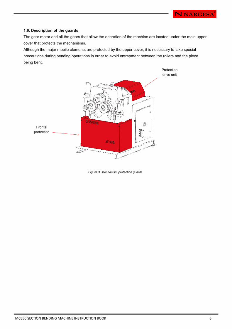
1.6. Description of the guards
The gear motor and all the gears that allow the operation of the machine are located under the main upper
cover that protects the mechanisms.
Although the major mobile elements are protected by the upper cover, it is necessary to take special
precautions during bending operations in order to avoid entrapment between the rollers and the piece
being bent.
Figure 3. Mechanism protection guards
Protection
drive unit
Frontal
protection
MC650 SECTION BENDING MACHINE INSTRUCTION BOOK 7
2. TRANSPORT AND STORAGE
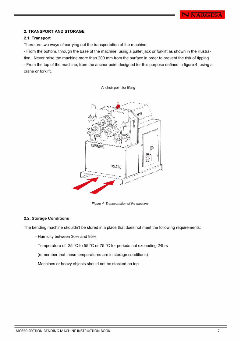
2.1. Transport
There are two ways of carrying out the transportation of the machine:
- From the bottom, through the base of the machine, using a pallet jack or forklift as shown in the illustra-
tion. Never raise the machine more than 200 mm from the surface in order to prevent the risk of tipping
- From the top of the machine, from the anchor point designed for this purpose defined in figure 4, using a
crane or forklift.
Figure 4. Transportation of the machine
2.2. Storage Conditions
The bending machine shouldn’t be stored in a place that does not meet the following requirements:
- Humidity between 30% and 95%
- Temperature of -25 °C to 55 °C or 75 °C for periods not exceeding 24hrs
(remember that these temperatures are in storage conditions)
- Machines or heavy objects should not be stacked on top
Anchoir point for lifting

MC650 SECTION BENDING MACHINE INSTRUCTION BOOK 8
CAUTION:
The "Emergency Stop" push button must be pressed and the machine brought to a stop in order to
lubricate the machine”.
3. MAINTENANCE
3.1. General maintenance
- To ensure correct operation and prolong service life, it is recommended to clean the piston rods whenev-
er possible.
- It is advisable to keep the friction rule lubricated along which the upper roller support slides. It is also nec-
essary to ensure a minimum lubrication of the inner walls along which the upper roller support slides.
- Regularly check the oil level in the hydraulic tank at the bottom of the machine. To obtain a correct reading
of the oil level the lower rollers should be in their lower position.
In order to lubricate the moving parts of the machine that require lubrication, it’s recommended to follow the
next instructions:
- Clean the surface to be lubricated with a cotton cloth or a soft rag that does not release any threads. To
remove the accumulated grease and any possible residues that have become stuck to it.
- After cleaning, reapply grease onto the surface with the help of a rag or a spatula.
- Spread the grease evenly without creating excesses or clumps.
- Once the machine is lubricated, using the mobile control that manages the height of the upper roller, raise
this until it reaches its highest point.
- When the upper roller comes to a stop, reverse the direction of the piston to lower the roller down to its
lowest point.
- Repeat the operation to ensure that the friction rule is lubricated.
- Repetir la operación para asegurar el engrase de las regla de fricción.
- Lubricate the machine regularly, according to use.
* It is recommended to use lithium grease for the rollers N.850 EP-2.
To replace the hydraulic oil, the following is recommended:
- Check the oil level in the tank every 500 hours of use.
- The oil cap is located at the top of the tank. If it is necessary to add oil, fill to the level of the sight glass
at the front of the tank.
- Change the hydraulic oil in the tank every 2000 hours of work or every 5 years.
- Remove the old oil in a tray and dispose of it at the nearest recycling point.
- Fill the tank with new hydraulic oil to the level of the sight glass located at the front. The capacity of the
tank is approximately 13 litres.
- Return the hydraulic assembly to its location and secure it to the machine with the
bolts.
* We recommend the use of CEPSA HIDRÁULICO HM 68 hydraulic oil.

MC650 SECTION BENDING MACHINE INSTRUCTION BOOK 9
4. INSTALLATION AND START UP
4.1. Positioning the machine
Locate the machine properly in order to avoid moving it; otherwise, follow the guidelines described in the
paragraph transport (no. 2). Must be placed on a flat, level surface to prevent it vibrating and moving during
bending operations.
It is optional to fix the machine by the four bolts since it is provided with a lower base or stand with four per-
forations as it’s shown in Figure 5.
Figure 5. Anchor points of the machine
4.2. Dimensions and work area
The dimensions must be considered when the machine is being placed, the working area for the operator
and the possible lengths of the parts to be worked.
The bending machine can be used by a single operator, who must be directly in the front of the machine to
be able to handle the piece being bend with safety, and never on the side.
Prior to commencing the bending operation, with the machine shut down, the operator must adjust the
Figure 6. Operator's working area
4.3. External permissible conditions
It is advisable to work under the following atmospheric conditions:
- Room temperature between +5 °C and +40 ºC without exceeding an average temperature of +35 °C
within 24 hrs.
- Humidity between 30% and 90% without water condensation.
MC650 SECTION BENDING MACHINE INSTRUCTION BOOK 10
IMPORTANT: This machine must be connected to an electrical outlet with earthing contact.
4.4 Instructions for connecting to the power supply
The MC650 bending machine has a three-phase 230V/400V, 3 Kw motor to move the rollers and a three –
phase 230V/400V, 0.75 Kw motor to govern the hydraulic piston, both prepared to connect to a 400V
power supply. The machine must be connected through the the installed connector to a compatible power
supply complying with the specified requirements.
If you wish to connect the machine to 230V three-phase, it is necessary to carry out some modification in
the electric panel, which are:
- Change the main motor coil connection
- Change the hydraulic motor coil connection
- Adjustment of intensity range of motor keeper at the hydraulic.
- Change of motor keeper at the main engine.
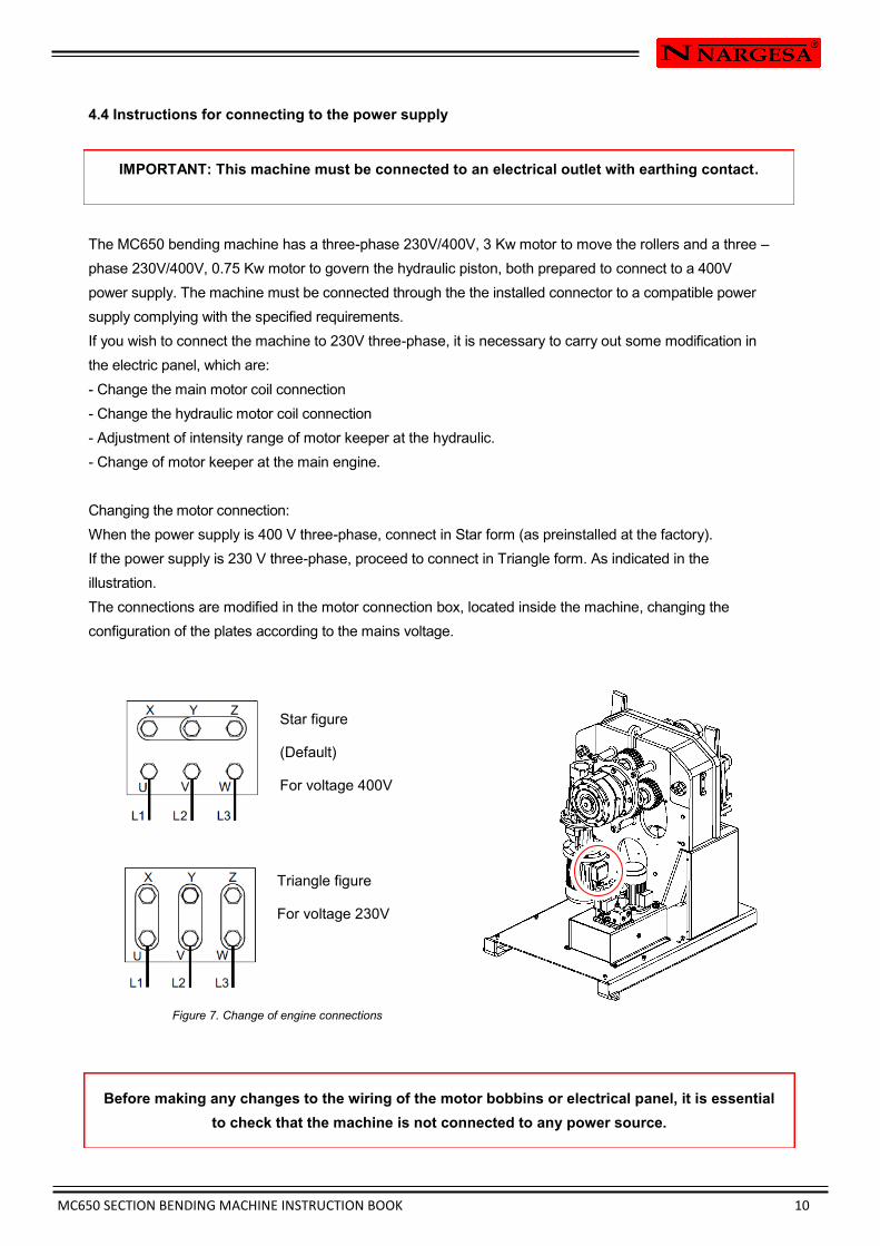
Changing the motor connection:
When the power supply is 400 V three-phase, connect in Star form (as preinstalled at the factory).
If the power supply is 230 V three-phase, proceed to connect in Triangle form. As indicated in the
illustration.
The connections are modified in the motor connection box, located inside the machine, changing the
configuration of the plates according to the mains voltage.
Figure 7. Change of engine connections
Triangle figure
For voltage 230V
Star figure
(Default)
For voltage 400V
Before making any changes to the wiring of the motor bobbins or electrical panel, it is essential
to check that the machine is not connected to any power source.
MC650 SECTION BENDING MACHINE INSTRUCTION BOOK 11
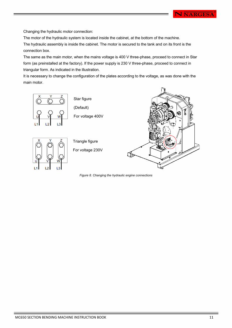
Changing the hydraulic motor connection:
The motor of the hydraulic system is located inside the cabinet, at the bottom of the machine.
The hydraulic assembly is inside the cabinet. The motor is secured to the tank and on its front is the
connection box.
The same as the main motor, when the mains voltage is 400 V three-phase, proceed to connect in Star
form (as preinstalled at the factory). If the power supply is 230 V three-phase, proceed to connect in
triangular form. As indicated in the illustration.
It is necessary to change the configuration of the plates according to the voltage, as was done with the
main motor.
Figure 8. Changing the hydraulic engine connections
Triangle figure
For voltage 230V
Star figure
(Default)
For voltage 400V
MC650 SECTION BENDING MACHINE INSTRUCTION BOOK 12
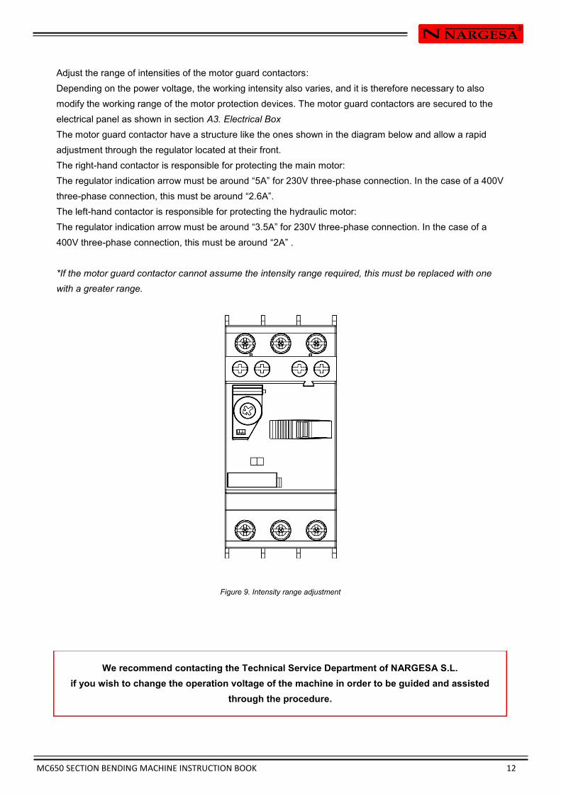
Adjust the range of intensities of the motor guard contactors:
Depending on the power voltage, the working intensity also varies, and it is therefore necessary to also
modify the working range of the motor protection devices. The motor guard contactors are secured to the
electrical panel as shown in section A3. Electrical Box
The motor guard contactor have a structure like the ones shown in the diagram below and allow a rapid
adjustment through the regulator located at their front.
The right-hand contactor is responsible for protecting the main motor:
The regulator indication arrow must be around “5A” for 230V three-phase connection. In the case of a 400V
three-phase connection, this must be around “2.6A”.
The left-hand contactor is responsible for protecting the hydraulic motor:
The regulator indication arrow must be around “3.5A” for 230V three-phase connection. In the case of a
400V three-phase connection, this must be around “2A” .
*If the motor guard contactor cannot assume the intensity range required, this must be replaced with one
with a greater range.
Figure 9. Intensity range adjustment
We recommend contacting the Technical Service Department of NARGESA S.L.
if you wish to change the operation voltage of the machine in order to be guided and assisted
through the procedure.
MC650 SECTION BENDING MACHINE INSTRUCTION BOOK 13
5. INSTRUCTIONS FOR USE
5.1. Bending principles
- The motor of the bending machine is controlled from the control panel.
- The radius of the curve is controlled by acting on the push buttons on the control panel, adjusting the
height of the two lower rollers.
- There is an emergency button on the panel.
- You can insert the material into the machine from either side. Use the position buttons to adjust the height
of the lower rollers and thus adjust admission of the material. By means of the limit switches, we can posi-
tion the final point of the lower rollers, separately, enabling you to obtain great position repeatability.
- To adjust the alignment of the material, it is necessary to modify the distance between the straighteners and
the work surface. This is done by acting on the nuts located at the back of the machine. These straighteners
guide the material so as to minimise lateral deformation. (The rollers of the straightener must press gently
against the section to be curved)
- In the event of not obtaining the proper results, the position of the guide rollers for deformation must be
adjusted.
- The roller mounting nuts must be tightened by manual force only .
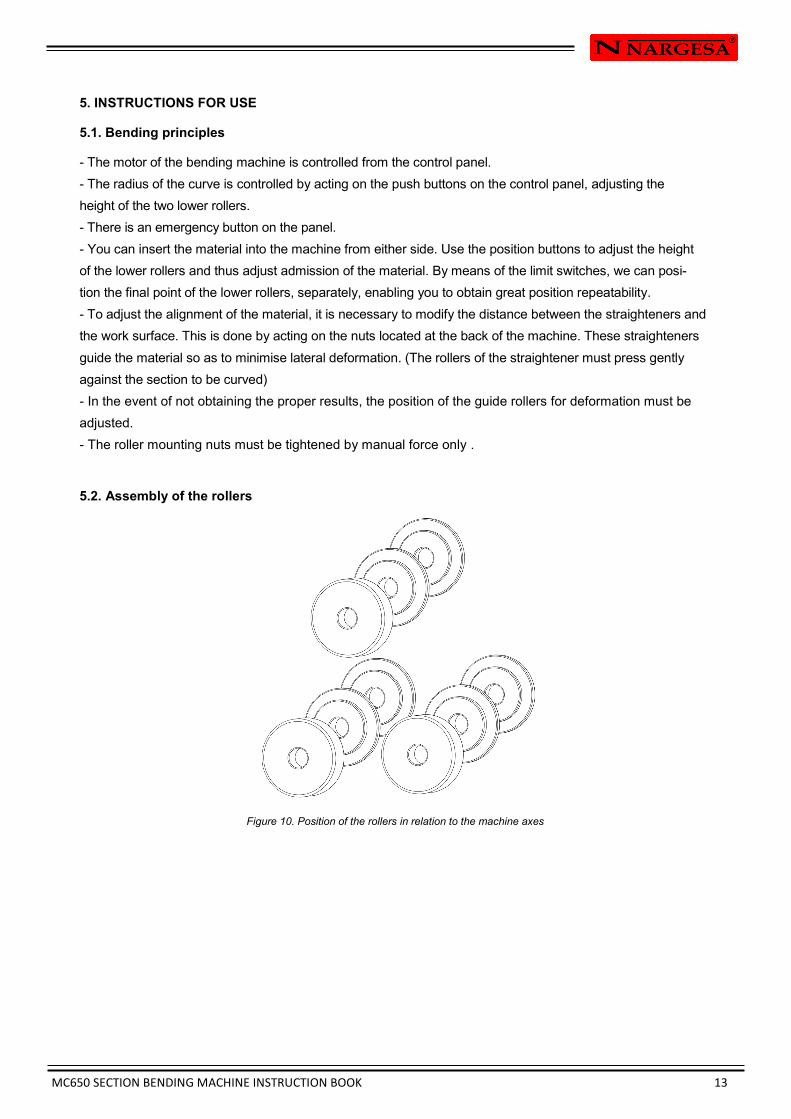
5.2. Assembly of the rollers
Figure 10. Position of the rollers in relation to the machine axes

MC650 SECTION BENDING MACHINE INSTRUCTION BOOK 14
5.3. Instruction manual
To control the operation of the MC650 hydraulic bending machine, there is a control desk from which
the machine can be controlled in a simple and intuitive manner.
9
4 11 1 2 3
10 6
7
5 5
1. Emergency stop
2. Of/On
3. Reset
4. Right roller position controllers
5. Selector
6. Roller position indicator
7. Potentiometer
8. Direction of rotation of rollers
9. Pilot lights
10. Roller position indicator
11. Left roller position controller
7 8 8
MC650 SECTION BENDING MACHINE INSTRUCTION BOOK 15
Nevertheless, to know the function of each of the elements of the control desk, it is recommended to read
the following sections:
5.3.1. Pilot lights
The control panel has three pilot lights, the function of each of which is explained below.
• White pilot light: Lights up when the main switch is in position 1 (ON), and informs that the bending
machine is powered. It is off when the main switch is in 0 position (OFF).
• Green pilot light: Is only on when the machine is powered and the reset button has been pressed. In
this case, the green pilot light comes on when the On button is pressed and it serves to indicates that the
bending machine is on and ready to work. It is off when the stop button or the emergency button has been
pressed, indicating that the machine is not in operation, even if it does have power.
• Red pilot light: Will only light up if the machine has mains power. In this case, the red pilot light
will come on when the emergency stop button is pressed, and it is used to indicate that there has been
an emergency stop. It will go off when the emergency stop lock has been released and the reset button
has been pressed.
5.3.2. Main buttons
To start and stop the bending machine, as well as to reset it, and carry out an emergency stop, the
control desk has the following buttons.
• On / Off switch: Integrating both switches in the same element, at the lower central part of the front of
the control desk, The On / Off control has two buttons, One red with an "O" symbol (Off button), and the
other green with the "I" symbol (On button). Therefore, they will turn on the machine if it is off and turn off
the machine if it is on respectively.
• Reset button: This blue button, located on the right of the on / off control, is used to reset the machine.
The machine must be reset whenever the machine is powered up and after an emergency stop.
• Emergency stop button: If there is a situation of danger during the use of the bending machine, before
anyone is injured, it is necessary to press the emergency stop button. Once the dangerous situation has
been dealt with, it is necessary to unlock the emergency stop button and then reset the machine to
continue working with it.
MC650 SECTION BENDING MACHINE INSTRUCTION BOOK 16
5.3.3. Roller position controllers
To control each of the pistons producing upward and downward movement of the left and right hand
rollers, the control desk has two different areas, one at each side of the front of the control desk.
Obviously, as they carry out identical functions regarding the control of each of the pistons, we will explain
the operation generically, without specifying which piston is being referred to, to make it more
comprehensible.
• Position indicator: The position indicator is formed by a collection of 7-segment displays, informing both of
the current position of the piston in question, and the maximum position limit value of the piston in
question. Obviously, these two parameters, although they are displayed on the same indicator, cannot be
shown simultaneously. To select the information you wish to see on the display, use the selector. In
one position it will display the current position of the piston being controlled and in the other, the
maximum position limit value of the piston in question. In addition, the position indicator has three LED
lights. The upper (when on) indicates that the piston still has upward travel to reach the limit (configured
by the user with a potentiometer). The central LED is a voltage indicator, and will always remain on while
the machine has voltage. Finally, the lower LED (when on) indicates that the piston still has downward
travel to reach the minimum limit (established electronically).
• Selector: As commented above, the selector is used to switch between the information displayed on the
position indicator of the piston being controlled. In one of its two positions, it enables the viewing of the
current position of the piston, while in the other it offers the maximum position limit of the piston in
question.
• Raise button: Makes the piston in question move upwards while being pressed, until it reaches the
maximum position limit.
• Lower button: Makes the piston in question move downwards while being pressed, until it reaches the
minimum position limit.
• Adjustment potentiometer for the maximum limit: Used to adjust the maximum limit position to be
reached by the piston.
5.3.4. Direction of rotation of rollers
On the front of the control panel, in addition to the aforementioned controls, you can also find two buttons
to control the direction of rotation of the rollers. To do this, just press and maintain pressed the button
corresponding to the desired direction, left or right.
MC650 SECTION BENDING MACHINE INSTRUCTION BOOK 17
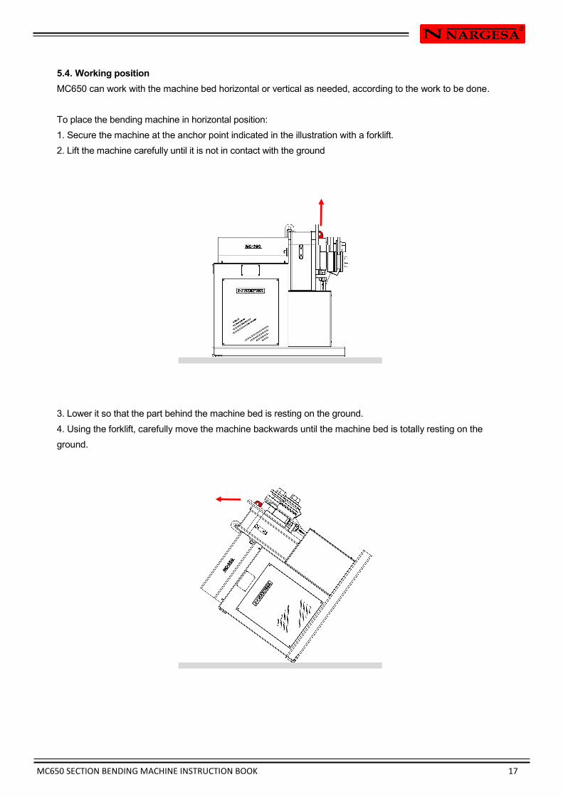
5.4. Working position
MC650 can work with the machine bed horizontal or vertical as needed, according to the work to be done.
To place the bending machine in horizontal position:
1. Secure the machine at the anchor point indicated in the illustration with a forklift.
2. Lift the machine carefully until it is not in contact with the ground
3. Lower it so that the part behind the machine bed is resting on the ground.
4. Using the forklift, carefully move the machine backwards until the machine bed is totally resting on the
ground.
MC650 SECTION BENDING MACHINE INSTRUCTION BOOK 18
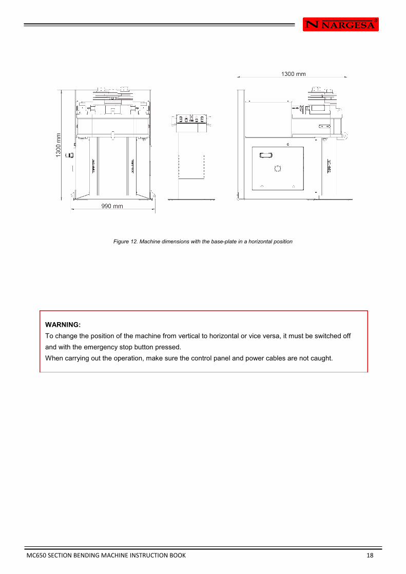
Figure 12. Machine dimensions with the base-plate in a horizontal position
WARNING:
To change the position of the machine from vertical to horizontal or vice versa, it must be switched off
and with the emergency stop button pressed.
When carrying out the operation, make sure the control panel and power cables are not caught.
MC650 SECTION BENDING MACHINE INSTRUCTION BOOK 19
6. WARNINGS
The MC650 bending machine is designed and assembled to allow the operator to handle the machine and
bend the necessary parts in a completely safe manner. Any change to the machine's structure or
characteristics could modify the safety offered by the machine, breaching the EC certificate of conformity
and could endanger the operator.
6.1. Residual hazards
Hazardous conditions may occur during the bending of materials that must be analysed and prevented.
Attention should be paid to the movements of the piece to be bent and the roller while the material is being
introduced into the machine as well as during its shaping. Despite the fact that the forward speed of the
rollers is slow, there is a risk of entrapment in the extremities between the rollers and the part.
Users of the machine are recommended to handle the part to be bent firmly with one hand and to move the
hand according to the progress of the bending operation in order to maintain a safe distance from the
rollers.
It is also necessary to prepare the work area to prevent other operators from injuring themselves during
operation of the machine.
6.2. Counter-productive methods
Tools or rollers that are not supplied by the manufacturer of the machine, NARGESA S.L., and which have
not been specially designed for the MC650 bending machine should never be used .
6.3. Other recommendations
- Use gloves for handling the machine and during the bending processes.
- Wear EC-approved goggles and protective boots
- Handle the material at the ends, and never around the area being bent
- Do not work without the protection devices that the machine is fitted with
- Ensure that there is a safe distance between the machine and the operator
MC650 SECTION BENDING MACHINE INSTRUCTION BOOK 20
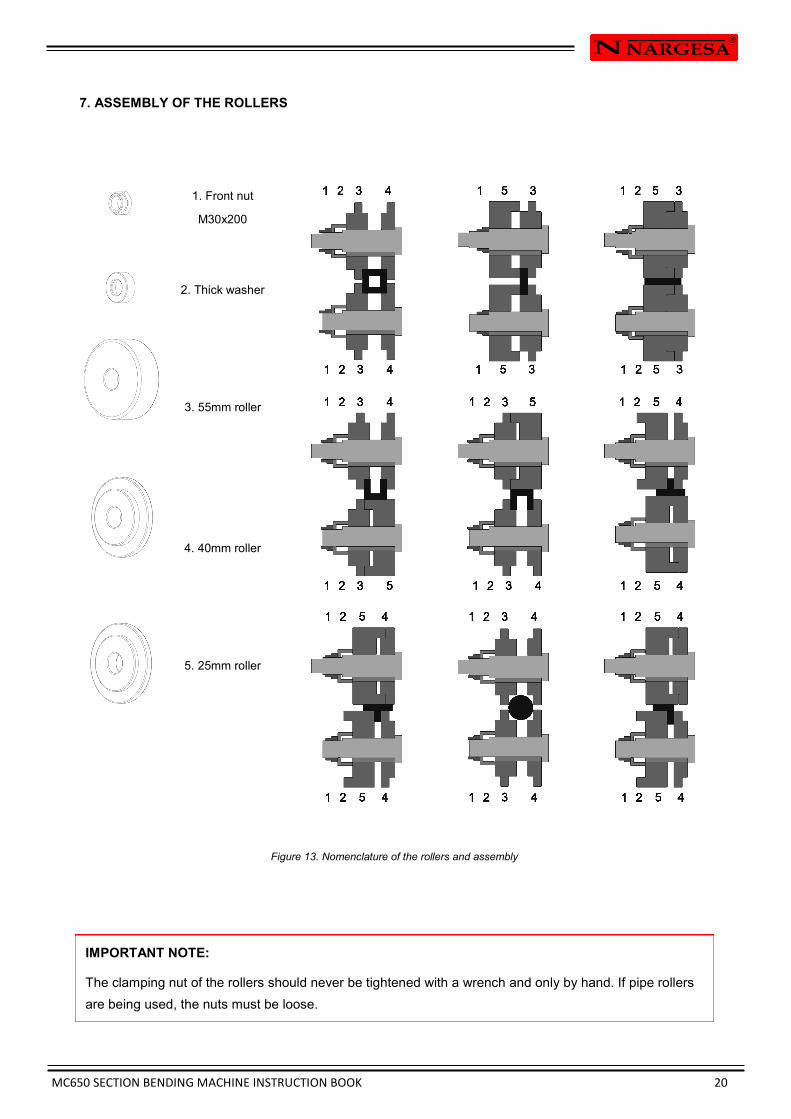
7. ASSEMBLY OF THE ROLLERS
IMPORTANT NOTE:
The clamping nut of the rollers should never be tightened with a wrench and only by hand. If pipe rollers
are being used, the nuts must be loose.
1. Front nut
M30x200
2. Thick washer
3. 55mm roller
4. 40mm roller
5. 25mm roller
Figure 13. Nomenclature of the rollers and assembly

MC650 SECTION BENDING MACHINE INSTRUCTION BOOK 21
7.1. Bending capacity
MC150B MC200 MC400 MC200H MC650
Profile Measures Min.
radius Measures
Min.
radius Measures
Min.
radius Measures
Min.
radius Measures
Min.
radius
50 x 8 300 50 x 10 300 50 x 10 250 60 x 10 200
100 x 20
80 x 20
1250
450
60 x 20 200 80 x 20 150 80 x 20 150 80 x 20 150
100 x 25
80 x 20
350
200
25 x 25 200 30 x 30 200 30 x 30 150 30 x 30 150
45 x 45
25 x 25
300
200
40 x 40 x 3 350 50 x 50 x 3 700 50 x 50 x 3 600 50 x 50 x 3 450
70 x 70 x 4
40 x 40 x 3
750
350
40 200 40 200 40 150 40 200
80 *
70
40
500
400
150
40 250 40 250 40 200 40 250
80 *
60
40
500
400
150
50 200 60 300 60 225 60 225
120
80
600
400
50 250 60 300 60 225 60 225
120
80
700
400
40 500 40 420 40 200 40 300
70
40
600
250
25 180 30 150 30 150 30 150
50
25
300
175
40 x 2 *
50,8 x 3 *
= 2” x 3 *
300
600
600
40 x 2 *
63,5 x 3 *
= 2”1/2 x 3 *
250
500
500
40 x 2 *
63,5 x 3 *
=2”1/2 x 3 *
200
450
450
40 x 2 *
76,2 x 2 *
= 3” x 2 *
200
500
500
88,9 x 4 *
101,6 x 3 *
= 4” x 3 *
700
700
700
* Optional rollers

MC650 SECTION BENDING MACHINE INSTRUCTION BOOK 22
1" WHITWORT = 25,401mm
When pipe sizes are smaller, two sizes are included in the same roller.
Eg. (25+30) or (1/2"+1"1/4)
It is advisable to clean up very well the rollers before using stainless
Steel to prevent from contaminating the pipe.
8. OPTIONAL ACCESSORIES
The bending machine has been designed for bending all kinds of profiles irrespective of their shape.
The standard rolls included as standard on the bending machine allow the configuration of all kinds of
handrails, angles, square, round pipes, etc., thanks to their multiple configurations.
In order to facilitate the bending of certain more delicate materials that require a very good surface finish
or to facilitate the bending of more common sections, NARGESA has designed a series of rollers that can
be purchased at an official dealership or by directly by contacting NARGESA S.L.
Besides the accessories shown below, NARGESA also designs special rollers upon specific request for
customers.
For pipe
in mm ISO mm Whitwort inchees Weight Weight Weight
(25+30) (17,2+21,3) (1/2”+1”1/4”) = (12,700 + 31,751 mm) 45,30 Kg 49,50 Kg 47,25 Kg
(20+35) (33,7+26,9) (1”+3/4”) = (25,401 + 19,051 mm) 44,80 Kg 43,75 Kg 48,00 Kg
40 42,4 1”1/2 = 38,101 mm 45,30 Kg 44,40 Kg 45,90 Kg
50 48,3 2” = 50,802 mm 40,80 Kg 41,60 Kg 40,70 Kg
60 60,3 2”1/2 = 63,502 mm 35,70 Kg 35,50 Kg 33,70 Kg
70 76,1 3” = 76,2 mm 64,70 Kg 60,20 Kg 60,20 Kg
80 88,9 3” 1/2 = 88,9 mm 57,40 Kg 50,35 Kg 50,35 Kg
90 101,6 4” = 101,6 mm 49,50 Kg 39,50 Kg 39,50 Kg
100 41,00 Kg
MC650 SECTION BENDING MACHINE INSTRUCTION BOOK 23
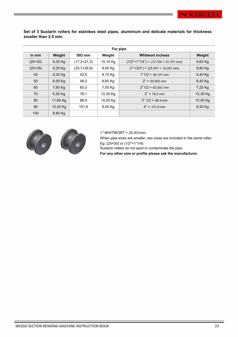
Set of 3 Sustarin rollers for stainless steel pipes, aluminium and delicate materials for thickness
smaller than 2.5 mm.
1" WHITWORT = 25,401mm
When pipe sizes are smaller, two sizes are included in the same roller.
Eg. (25+30) or (1/2"+1"1/4)
Susterin rollers do not spoil or contaminate the pipe.
For any other size or profile please ask the manufacturer.
For pipe
in mm ISO mm Whitwort inchees Weight Weight Weight
(25+30) (17,2+21,3) (1/2”+1”1/4”) = (12,700 + 31,751 mm) 9,35 Kg 10,10 Kg 9,65 Kg
(20+35) (33,7+26,9) (1”+3/4”) = (25,401 + 19,051 mm) 9,25 Kg 9,00 Kg 9,80 Kg
40 42,4 1”1/2 = 38,101 mm 9,30 Kg 9,15 Kg 9,40 Kg
50 48,3 2” = 50,802 mm 8,50 Kg 8,65 Kg 8,45 Kg
60 60,3 2”1/2 = 63,502 mm 7,60 Kg 7,55 Kg 7,25 Kg
70 76,1 3” = 76,2 mm 6,50 Kg 12,30 Kg 12,30 Kg
80 88,9 3” 1/2 = 88,9 mm 11,80 Kg 10,50 Kg 10,50 Kg
90 101,6 4” = 101,6 mm 10,35 Kg 8,50 Kg 8,50 Kg
100 8,80 Kg
MC650 SECTION BENDING MACHINE INSTRUCTION BOOK A 1
Technical annex
MC650 Bending Machine
General parts diagram
Hydraulic group
Straightener roller
Hydraulic cylinder
Electrical box
Electric maps
Hydraulic map

MC650 SECTION BENDING MACHINE INSTRUCTION BOOK A 2
A1. General parts diagram
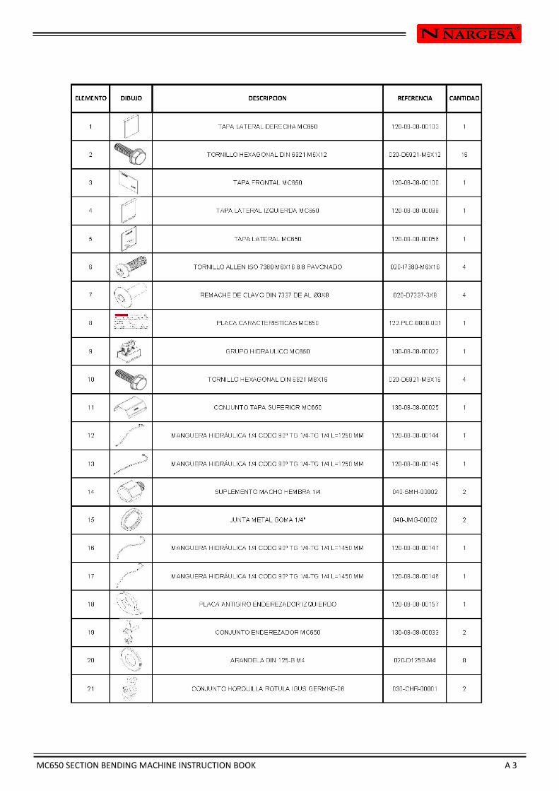
MC650 SECTION BENDING MACHINE INSTRUCTION BOOK A 3

MC650 SECTION BENDING MACHINE INSTRUCTION BOOK A 4
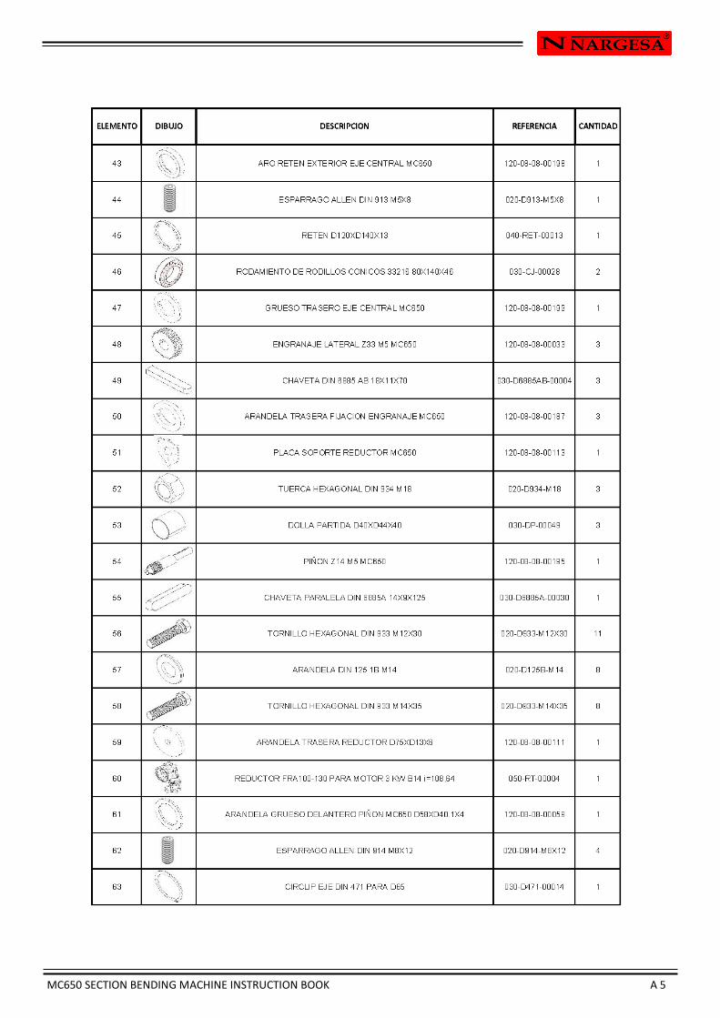
MC650 SECTION BENDING MACHINE INSTRUCTION BOOK A 5
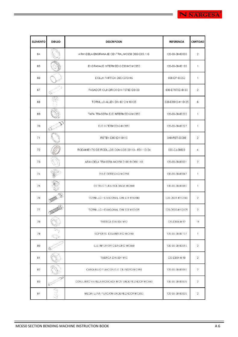
MC650 SECTION BENDING MACHINE INSTRUCTION BOOK A 6

MC650 SECTION BENDING MACHINE INSTRUCTION BOOK A 7

MC650 SECTION BENDING MACHINE INSTRUCTION BOOK A 8
MC650 SECTION BENDING MACHINE INSTRUCTION BOOK A 9
A2. Hydraulic group
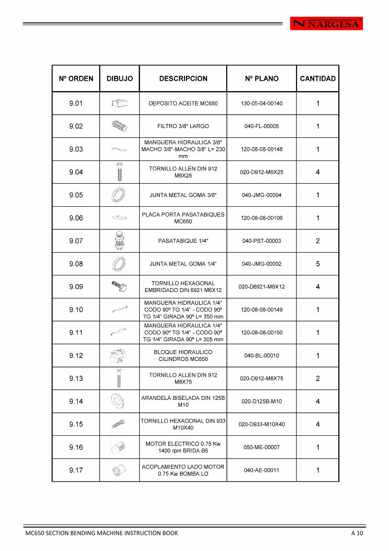
MC650 SECTION BENDING MACHINE INSTRUCTION BOOK A 10

MC650 SECTION BENDING MACHINE INSTRUCTION BOOK A 11
MC650 SECTION BENDING MACHINE INSTRUCTION BOOK A 12
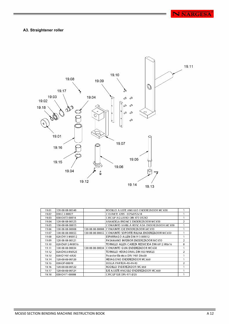
A3. Straightener roller
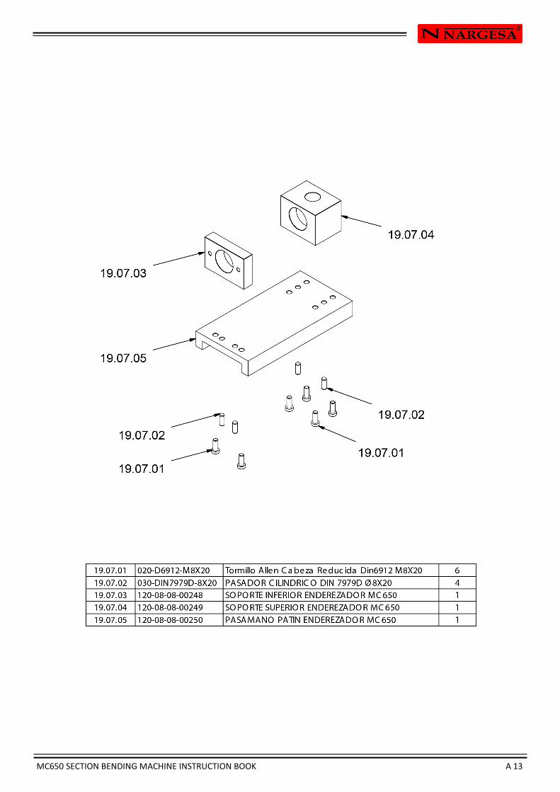
MC650 SECTION BENDING MACHINE INSTRUCTION BOOK A 13
MC650 SECTION BENDING MACHINE INSTRUCTION BOOK A 14
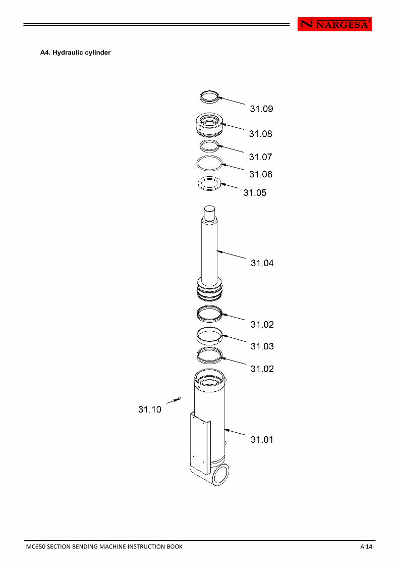
A4. Hydraulic cylinder
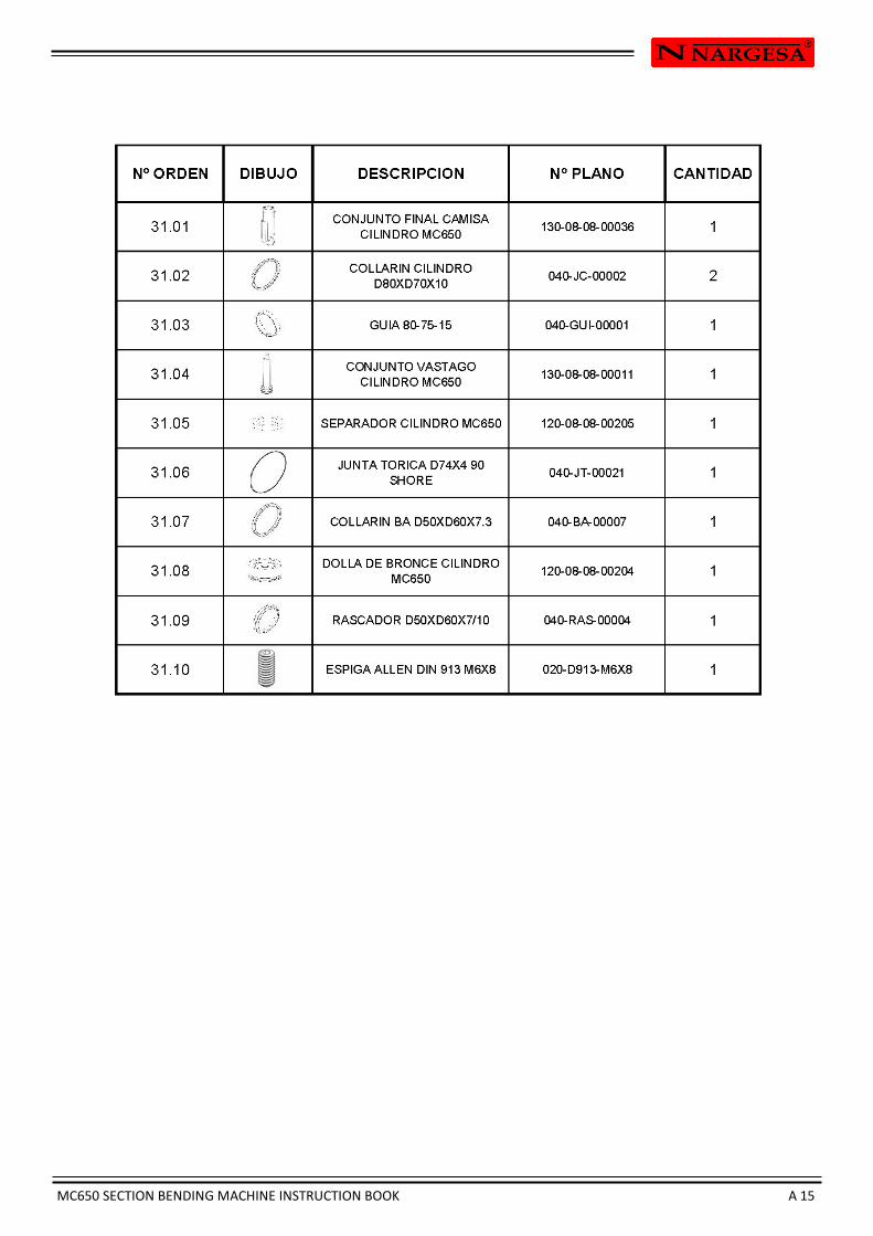
MC650 SECTION BENDING MACHINE INSTRUCTION BOOK A 15
MC650 SECTION BENDING MACHINE INSTRUCTION BOOK A 16
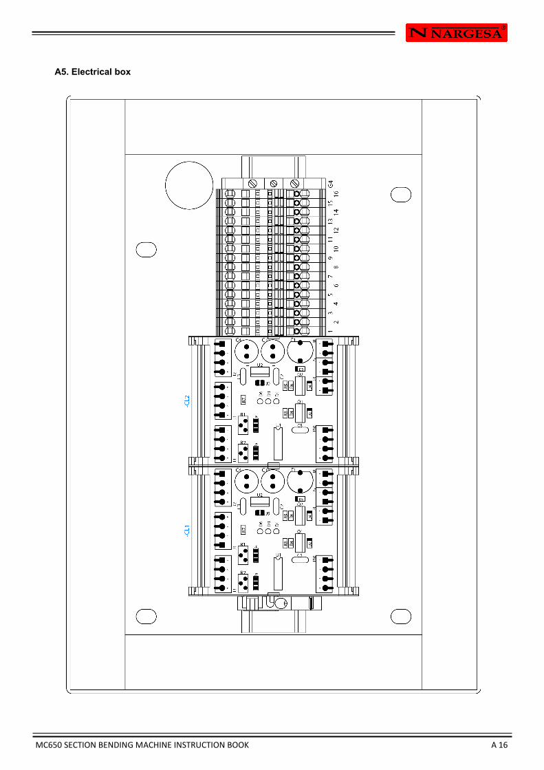
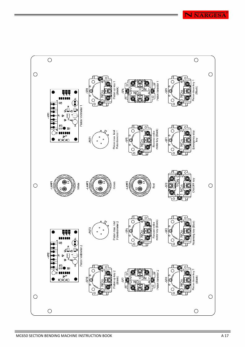
A5. Electrical box
MC650 SECTION BENDING MACHINE INSTRUCTION BOOK A 17
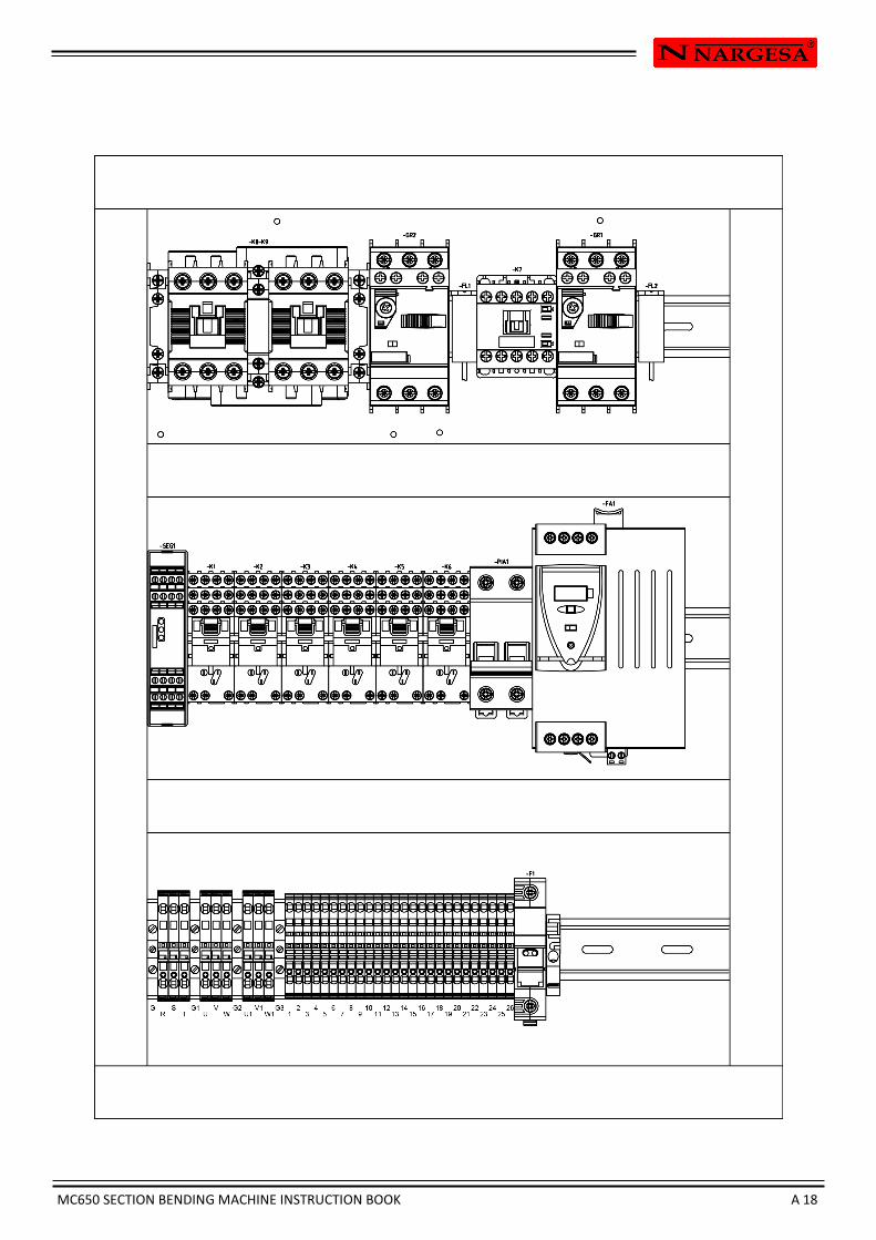
MC650 SECTION BENDING MACHINE INSTRUCTION BOOK A 18

MC650 SECTION BENDING MACHINE INSTRUCTION BOOK A 19
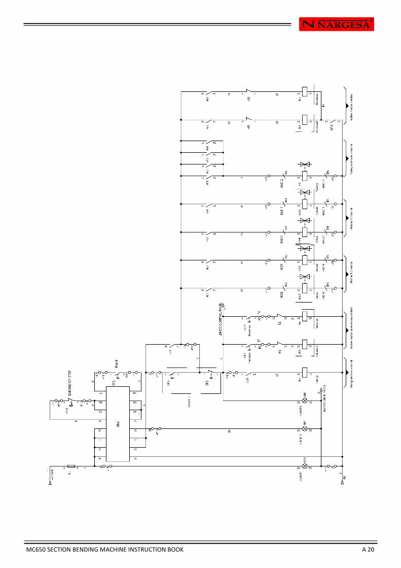
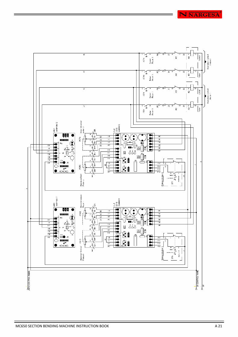
A6. Electric maps
Pump motor Roller motor
MC650 SECTION BENDING MACHINE INSTRUCTION BOOK A 20
MC650 SECTION BENDING MACHINE INSTRUCTION BOOK A 21
MC650 SECTION BENDING MACHINE INSTRUCTION BOOK A 22
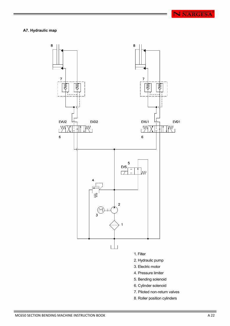
A7. Hydraulic map
1. Filter
2. Hydraulic pump
3. Electric motor
4. Pressure limiter
5. Bending solenoid
6. Cylinder solenoid
7. Piloted non-return valves
8. Roller position cylinders
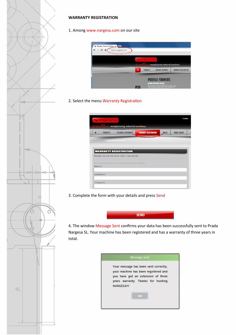
WARRANTY REGISTRATION
1. Among www.nargesa.com on our site
2. Select the menu Warranty Registration
3. Complete the form with your details and press Send
4. The window Message Sent confirms your data has been successfully sent to Prada
Nargesa SL. Your machine has been registered and has a warranty of three years in
total.