section eight
TRANSCRIPT

©Informa Telecoms
UMTS System Overview
Procedures


UMTS System Overview©Informa Telecoms
Procedures
1. UMTS PROCEDURES – GENERAL1.1 UMTS Defined Procedures 11.2 UE Identifiers (Held by the User Equipment
and Core Network) 31.3 UTRAN Identifiers 51.4 UMTS Areas 7
2. MODES AND STATES2.1 Service States 92.2 UTRAN RRC States 11
3. EXAMPLE RRC PROCEDURES3.1 RRC Idle Mode 133.2 RRC Connection Establishment 153.3 Paging 173.4 Handover Types 193.5 The Soft Handover Procedure 213.6 Hard Handover 233.7 Compressed Mode 25
4. UTRAN PROCEDURES4.1 Example – Power Control 27
5. NON-ACCESS STRATUM PROCEDURES5.1 The Mobility Management Concept 295.2 NAS Procedures Example – Service Registration
and Updates 315.3 NAS Procedures Example – PDP Addresses & Context
(Session Management) 335.4 PDP Context States 355.5 NAS Procedures Example – Detach 375.6 Call Set-up, Routing & Addressing 395.7 CAMEL Interactions 41

1.1 UMTS Defined Procedures
The procedures described in the first phase of UMTS specifications concentratepredominantly on the air interface and UTRAN.
The Core Network is considered as an evolved GSM network, hence the proceduresare those specified for the GSM Core Network, including GPRS. As networkoperators move to an All-IP network, the procedures in the core network will reflectthis and will be based more on the IETF (Internet Engineering Task Force)specifications.
As the core network is not the subject for UMTS standardisation, it follows that theway it interacts with UE will remain essentially that specified for GSM. Hence, whenconsidering UMTS procedures, we can initially concentrate on the Air Interface andUTRAN.
It is still useful to examine the Non-Access stratum and Core Network procedures inorder to show the overall system operation, and how UTRAN and Air Interfaceprocedures fit into the bigger picture.
UMTS System Overview
1. UMTS PROCEDURES – GENERAL
Procedures
©Informa Telecoms1

CoreNetwork
Uu Iu
Procedures Basedon Evolved GSM/GPRS
Network
Procedures Defined inUMTS (+ Lower Layers)
RANAPRRC
RRC
UTRAN
Non Access Stratum
Fig. 1 – UMTS Procedures - General
2©Informa Telecoms

1.2 UE Identifiers (Held by the User Equipment and Core Network)
The identifiers held by the User Equipment and Core Network are shown opposite:
The IMSI (International Mobile Subscriber Identity) is used in the network to identifythe Subscriber Identity Module (SIM), or UMTS SIM (USIM) within the mobile. It isheld within the location registers in the network against information, including theservices supported, current location (down to Location Area - LA or Routing Area –RA only), and status for that mobile. It is unique to the mobile in question as it reflectsthe Mobile Country Code, Mobile Network Code, and Subscriber Identity within thatnetwork.
The TMSI (Temporary Mobile Subscriber Identity) is used as a code word for the IMSIover the radio interface. It is shorter than the IMSI and unique only within the Visitorlocation Register (VLR) / Mobile Switching Centre (MSC) area. It is changed at regularintervals by the VLR in order to maintain security.
The P-TMSI (Packet TMSI) is essentially similar to the TMSI, but is used in theServing GPRS Support Node (SGSN) rather than in the VLR. Again, it is used as acode word and changed at regular intervals.
The IMEI (International Mobile Equipment Identity) is used to identify the mobileequipment itself, rather than the subscriber (via the Subscriber Identity Module).Through its numbering structure it gives details of the manufacturer, model, typeapproval code, and importantly in terms of procedures, its capabilities can thereforebe assessed.
The TLLI (Temporary Logical Link Identity) is used between the SGSN and UserEquipment to identify the established logical link for packet services. It is uniquewithin the Routing Area.
UMTS System Overview
Procedures
©Informa Telecoms3

Fig. 2 – (Core Network) UE Identities
4©Informa Telecoms
•IMSI
•TMSI
•P - TMSI
•IMEI
•TLLI
1.3 UTRAN Identifiers
The procedures defined within the UTRAN are extensive. Since mobility is anessential requirement of any mobile network, it is important to be able to identify theelements and areas concerned. The figure shown opposite illustrates how thedifferent elements within the UTRAN are identified.
It shows how the network elements are identified, together with the cell areas and thePublic Land Mobile Network itself.
The UE may have Radio Network Temporary Identifiers (RNTI) assigned by theServing, Drift and Controlling RNC. It allows a level of identification separate to thatused by the Core Network (IMSI / TMSI), which allows some mobility procedures tobe handled entirely within the UTRAN. The RNTIs are applicable to the Serving, Drift,or Controlling RNC. These are otherwise known as the Cell RNTI.
The U-RNTI is also used for certain procedures, which is a “long” UTRAN UE identityused to ensure routing of uplink messages to the UE’s Serving RNC, irrespective ofthe receiving RNC.
The cell is identified (UTRAN Cell Id) using a hierarchical scheme which takes itscontrolling RNC Identity and adds a cell identity to it. Because the Global RNCIdentity includes the Public Land Mobile Network Identifier (PLMN Id), it is a uniqueidentifier, and so therefore is the UTRAN Cell Id. The PLMN Id is made up of a MobileCountry Code and Mobile Network Code.
From the UTRAN, the core network domains use identifiers which include the PLMNId and either the Location Area Code (LAC) for the Circuit Switched Domain, or theLAC and Routing Area Code (RAC) for the Packet Switched Domain.
UMTS System Overview
Procedures
©Informa Telecoms5

CORE NETWORK
SGSN MSC
RNC RNC RNC RNC
PLMN
Node B
Note: The URNTI is also used in certain procedures
CN CS Domain-Id=PLMN-Id+LACCN PS Domain-Id
=PLMN-Id+LAC+RAC
Serving RNC RNTI (s-RNTI)Drift RNC RNTI (d-RNTI)Controlling RNC RNTI
(c-RNTI)
UTRAN Cell IdentityUC-ID=RNC-Id+C-Id
Global RNC-Id=PLMN-Id+RNC-Id
PLMN-Id=MCC+MNC
Fig. 3 – UTRAN Identifiers
6©Informa Telecoms

1.4 UMTS Areas
The cells in UMTS are organised into a series of areas for mobility purposes.
The basic area is that of the cell itself.
A number of cells (varying from a single cell to all the cells in the area served by aCore Network Node, i.e. MSC / VLR area), are grouped into location areas. A mobileis tracked on a location area (LA) basis by the Visitor Location register (VLR). Anyincoming calls result in the mobile being paged over all the cells in the Location Area.This negates the need for the mobile to update its position constantly as it movesfrom cell to cell when it would otherwise be in idle mode (saving power and reducinginterference and load on the radio network). Of course, a bigger LA requires morecells to carry the paging message.
The Routing Area (RA) is a subset of the LA (with cells numbering between one andall the cells in the LA). The boundary of the RA must be coincident with, or confinedwithin the LA boundary. The RA is used in the Packet Switched Core Network in asimilar way that the LA is used in the Circuit Switched, but it gives a greater degree ofaccuracy and flexibility.
In addition, the UTRAN Registration Area (URA) is specified for use within the UTRAN(the Core Network is not aware of this area). Once in the connected mode, the mobileis allowed to fall back into a less active state if using shared channels (only applicablefor packet services). In this case, the UTRAN can track the mobile on a cell-by-cell orURA-by-URA basis. The mobile will signal the UTRAN if it changes cell or URA arearespectively. So far as the Core Network is concerned, the mobile is still in connectedmode. This means data is forwarded through to the UTRAN as if the mobile wereconnected, without any paging being initiated. The UTRAN would then initiate thepaging to bring back the mobile into a more active connected mode.
A cell can belong to several URAs at once. Only if the mobile detects that its currentURA is not on the list within its current cell would a URA update procedure beexecuted. This reduces the signalling required to inform the Serving RNC of themobile’s current location.
Other areas used in relevant procedures include RNC, MSC, VLR and SGSN.
UMTS System Overview
Procedures
©Informa Telecoms7

Cell, with base site
UTRAN Registration Area (PS Services)
Routing Area (PS Services)
Location Area (CS Services)
To Core NetworkElement(s) (Via RNCs)
UMSCMSC / SGSN
Area
Used byUTRAN only
Known byCore Network
Fig. 4 – UMTS Areas
8©Informa Telecoms
• In addition, RNC, MSC, VLR and SGSN areas are all identifiable.
2.1 Service States
The Service State is used to describe the activity of the mobile. In each case, themobile can be in one of three modes, or states. They are used in both the corenetwork and UE to model activity.
State models are used in both the Packet and Circuit Switched domains. In eachcase, the mobile is considered Idle, Connected or Detached.
An example of where the state would affect the service is that for an incoming call. A detached mobile may be configured to forward to voice mail, an idle mobile wouldbe paged in order to establish a connection to receive the call, and a mobile alreadyconnected to the network could have forwarding (again possibly to voice mail), or callwaiting active.
UMTS System Overview
2. MODES AND STATES
Procedures
©Informa Telecoms9

UTRAN
MSC/VLR SGSN
CSServiceState
PSServiceState
No Knowledgeof Service State
in UTRAN
CS IDLECS CONNECTEDCS DETACHED
PS IDLEPS CONNECTEDPS DETACHED
CS Service State& PS Service State
Fig. 5 – Service States
10©Informa Telecoms

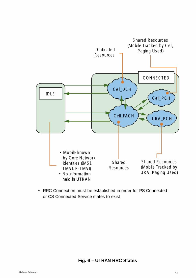
2.2 UTRAN RRC States
States are also used within the UTRAN. They are actually termed the Radio ResourceControl (RRC) states. The mobile can be either in idle or connected mode.
Idle is where the mobile is switched on and monitoring network system informationon the Broadcast Channel. The core network holds location information (LA Id for theCS domain, and RA Id for the PS domain), but no information is held within theUTRAN.
Connected, where the mobile has an established connection through the UTRAN tothe core network. In the packet switched case, this can be in the form of anestablished logical link (denoted by the Temporary Logical Link Identity).
The Core Network will be connected to the mobile for circuit switched services (in theCell_DCH state) and location will not be a problem. For packet switched services, themobile may be in the Cell_DCH state, or in the Cell_FACH state, from where it can fallback to one of two less active states, known as URA_PCH, and Cell_PCH.
The designators give a good clue as to the purpose of each state. The first part (Cellor URA) indicates the accuracy of mobile tracking being performed in the UTRAN.The second part indicates the type of resources being used in that state. For DCH,dedicated channels are being used. For FACH, shared channels are being utilised bythe mobile. But for PCH, the mobile is simply monitoring the paging channel andproviding location information to the UTRAN when URA or cell boundaries arecrossed (depending on whether in the URA_PCH or Cell_PCH state).
As explained, therefore, the RRC states are closely related to the use of the differentUMTS areas.
UMTS System Overview
Procedures
©Informa Telecoms11
URA_PCH
Cell_DCH
Cell_PCHIDLE
Cell_FACH
• Mobile known by Core Network
identities (IMSI, TMSI, P-TMSI)• No information
held in UTRAN
SharedResources
DedicatedResources
Shared Resources(Mobile Tracked by Cell,
Paging Used)
Shared Resources(Mobile Tracked byURA, Paging Used)
CONNECTED
Fig. 6 – UTRAN RRC States
12©Informa Telecoms
• RRC Connection must be established in order for PS Connected or CS Connected Service states to exist

3.1 RRC Idle Mode
The tasks of the mobile in idle mode are shown opposite:
The mobile continuously monitors the System Information Broadcasts on theBroadcast Channel, interpreting the information appropriately. This informationcontains parameters such as the serving cell id, UTRAN registration area identitiesand information on how to access the network (random access information – codesand slots).
The mobile selects the Public Land Mobile Network, and the required cell, based onmeasurements taken on the radio interface, and the cell selection / reselectionalgorithms.
Once the cell is selected, the mobile leaves the idle state to register its location withthe network. In the absence of any other activity, it then falls back to the idle mode,to monitor the paging channel (within its assigned paging block), updating its locationas required (periodically, or as Location Area or Routing Area boundaries aretransited).
UMTS System Overview
3. EXAMPLE RRC PROCEDURES
Procedures
©Informa Telecoms13

RRC
Fig. 7 – RRC Idle Mode
14©Informa Telecoms
IDLE MODE:
• Monitor System Information Broadcast
(Contains MM Information).
• PLMN Selection and Reselection
• Cell Selection
• Cell Reselection
• Location Registration and Updating
• Monitor Paging Channel/Block

3.2 RRC Connection Establishment
This is instigated from Idle mode. The RRC Connection Request is sent from themobile to the controlling RNC (which becomes the Serving RNC as the connection isestablished) on a Common Control Channel, CCCH (which is a bi-directional logicalchannel used to transfer control information between the network and UEs). TheCCCH is always mapped in the uplink to the Random Access Channel (a transportchannel), which itself allows mobiles to access the network randomly as arequirement arises. This may be to make a call, transfer data, or update a Location orRouting Area.
The Serving RNC now sets up the Radio Link over the Iub interface, including thedata bearer setup within the ATM (Asynchronous Transfer Mode) transport network.Once achieved, the RRC Connection setup indication is sent to the UE over theCCCH (now using the Forward Access Channel, FACH (a transport channel) in thedownlink.
The mobile now moves into the connected state, sending a RRC Connection SetupComplete indication to the Serving RNC on the designated dedicated channel.
UMTS System Overview
Procedures
©Informa Telecoms15

RRC
RRC RRC
RRC RRC
RRC RRC
UE NODEB
(RACH CCCH) RRC Connection Req
(FACH CCC) RRC Connection Setup
(DCCH) RRC Connection Setup Complete
SERVINGRNC
Radio Link Setup (IncludingIub Data Bearer Setup)
RRCConnected
RRC Idle
Fig. 8 – RRC Connection Establishment (DCH)
16©Informa Telecoms

3.3 Paging
Paging can be initiated either by the Core Network, for mobiles in Idle Mode, or bythe Serving RNC for mobiles in the URA_PCH or Cell_PCH mode.
For Idle mobiles, the paging is initiated over the required Location Area, or RoutingArea for incoming calls, or for session setup in the case of packet services. The corenetwork node (MSC / VLR or SGSN) initiates the procedure over the Iu interface usingRANAP (Radio Access Network Application Part) signalling in this case.
If the mobile is in the URA_PCH or Cell_PCH state, the Serving RNC responds toincoming (downlink) packet data activity by paging the mobile over the appropriateURA or Cell respectively. This is done to bring the mobile into the Cell_FACH stateready for data transfer.
In core network initiated, or RNC initiated cases, the Paging message is broadcast byRRC on the PCCH (Paging Control Channel).
In addition, the RNC can indicate a change of system information by using a pagingmessage with no paging record, but with the new information carried within it. Thesemessages would be aimed at all UEs in a cell.
UMTS System Overview
Procedures
©Informa Telecoms17

RRC
Core Network
Paging
(-RRC)
(PCCH)
Paging (-R
RC
)
(PC
CH
)
Paging
Paging (-R
RC
)
(PC
CH
)
Paging
RANAP
RNCRRC
RNCRRC
Fig. 9 – Paging (Eg RRC Idle Mode)
18©Informa Telecoms
• Core Network knows LA or RA of UE• Applicable to RRC Idle Mode (No RRC Connection),
or RRC Connected Mode Cell_PCH and URA_PCH states• For RRC Connected Mode (Cell_DCH and Cell_FACH), DCCH would be
used with existing RRC connection – no paging required
3.4 Handover Types
There are three different handover types in UMTS:
The Softer handover is where the mobile receives the signal via two radio interfacesat the same time, both interfaces being provided by the same Node B. Theinformation from the different sectors, or cells, is handled by the same Node B, hencecombining is done within the Rake receiver.
The Soft handover is where the mobile receives the signal via two radio interfaces atthe same time, but the interfaces are provided by different Node Bs. The informationfrom the different cells is channelled from both Node Bs to the serving RNC (possiblyvia a Drift RNC) handled by different Node Bs, hence combining is done now in theRNC.
Hard handover is the same sort of handover found in GSM, where the new radioresources are established, and the mobile makes contact via the new resourcesbefore the old resources are released. Communication only ever occurs via a singleinterface. This can be used for handover between WCDMA frequencies, or betweendifferent systems.
UMTS System Overview
Procedures
©Informa Telecoms19

NodeB
NodeB
• Softer Handover
• Soft Handover
• Hard Handover
• Hard Handover
NodeB
NodeB
RNC
NodeB
BTS
MSC
UTRAN
GSM BSS
Carrier 2
Carrier 1
Fig. 10 – Handover Types
20©Informa Telecoms
3.5 The Soft Handover Procedure
The soft handover procedure relies on an active set of cells being maintained. It isapplicable only to mobiles in the RRC Connected Cell_DCH state.
This active set simply includes the cells, which are currently providing a radiointerface for the mobile in question. Addition and deletion to and from the active setis carefully controlled, based on a soft handover algorithm. The parameters for thisalgorithm are configurable, and allow cells to be added and deleted by the ServingRNC based on measurement reports continually being sent in by the mobile.Hysteresis and “time above or below specified values” minimise the number of activeset updates required, and hence signalling is minimised.
The mobile itself monitors system information messages sent from the network toidentify candidate (neighbouring) cells. Once known, the active and candidate cellpilot channels are monitored and appropriate measurement reports sent in to thenetwork, allowing the energy per chip and interference to be assessed. The RNC thenuses this information in the soft handover algorithm.
The active set update message contains the information required for a mobile toaccess the network via the required cells (codes etc.). Typically, one, two or threecells will be in the active set at any one time. A maximum number can be set.
UMTS System Overview
Procedures
©Informa Telecoms21

CELL_DCHState
UE ServingRNC
RRC RRC
RRC RRC
(DCCH) Active Set Update
System Information
Measurement Reports
(DCCH) Active Set Update Complete
UE
RRC
Fig. 11 – Soft Handover Procedure
22©Informa Telecoms
• Based on Measurement Reports, Serving RNC assesses the Pilot channels ofactive and candidate cells.
• Cells can be added, replaced or removed from the active setbased on:- Energy per “chip” and interference- Max number of cells in active set- Hysteresis and required time at measured value

3.6 Hard Handover
For the hard handover, the mobile monitors the appropriate radio resources, sendingthe required measurement reports into the network. The network sends systeminformation messages to the mobile, which are used to identify the resources to bemonitored.
The Serving RNC assesses the measurement results and may decide to hand overfrom one WCDMA frequency to another, or from UTRAN to GSM BSS. The first casemay be achieved within the UTRAN, but the inter-system handover necessitates theinvolvement of the core network, as shown.
UMTS System Overview
Procedures
©Informa Telecoms23

MSC
RANAP
RRC
(Gsm)BSSAP
Core NetworkConnection
* H/O Command to GSMGSM H
/O A
cces
s Measurement Reports
System Information
UE
UTRANRNC
(GSM)BSS
Ackno
wledgements (with GSM
Info)
“Req
uired”Relocation
Request
* RRC Physical Channel
Reconfiguration Message
1
2
5
3
4
6
RRC, RANAP, BSSAP
Fig. 12 – Hard Handover (Example - UMTS to GSM)
24©Informa Telecoms

3.7 Compressed Mode
For a mobile to monitor resources, on anything other than the WCDMA frequency it is currently using requires a break in reception. This is required because the mobilecannot operate on two frequencies, or therefore on two systems, at once, andWCDMA operation is continuous (unlike Time Division Multiple Access (TDMA)systems, such as GSM, which effectively have gaps between time slots which areused to monitor other cell transmissions).
Compressed mode is used in WCDMA to give the break required. It is a techniqueused to compress (rather than lose) data in order to provide a sufficient gap.
In normal operation, each frame is 10ms long, the time taken to transmit the data canbe compressed by:
• Reducing the data rate from the upper layers (although in this case, less data isactually transmitted)
• Lowering the spreading factor so that fewer chips are used to represent the sameamount of data (same amount of data transmitted, but with potentially poorerquality)
• Reducing the symbol rate by “puncturing at the physical layer” (taking outunnecessary data, and relying more on forward error correction to maintain quality)
Each frame is made up of a possible 15 slots, and two adjacent frames wouldtherefore have 30 slots available. Out of the 30 slots, 3, 7, 10, 14 slot gaps can beconfigured.
UMTS System Overview
Procedures
©Informa Telecoms25

10ms 10ms 10ms 10ms
Power
TransmissionGap Length
3,7,10 or 14 slots
Fig. 13 – Compressed Mode (Slotted Mode)
26©Informa Telecoms
Compressed Mode - Allows time for other UMTS frequencies to be measured.
Achieved by:1. Lower data rates from upper layers.2. Increasing data rate by changing spreading factor.3. Reducing symbol rate by “puncturing” at physical layer.

4.1 Example – Power Control
Power control is required to minimise the interference in the system.
Fast closed loop power control is performed 1500 times a second and is designed toadjust the power to meet a defined signal to interference (SIR) ratio. The SIR is set to give the required quality whilst minimising the contribution to overall systeminterference. Outer loop power control is the process of changing the SIR.
Outer loop power control is usually implemented in the Radio Network Controller(RNC), which performs checks on some form of frame quality indicator which istagged along with the user data to indicate when error rates become unacceptable.
The RNC informs the Node B of changes to SIR using Node B Application Part(NBAP) messages. If required, more than one Node B, each with cells in the active setfor a given mobile will be sent the required SIR, as shown. This can be extended viathe Drift RNC where cells belonging to different RNCs are involved.
Open loop power control is the third type, which is applied by the mobile only prior toinitiating transmission on the RACH or CPCH. It is not very accurate, since accuratepower assessments are difficult to achieve in the mobile. Also, information on powergained in the downlink is then applied to transmissions in the uplink, which is at alarge duplex spacing.
UMTS System Overview
4. UTRAN PROCEDURES
Procedures
©Informa Telecoms27

UENode B
Drift RNSNode B
Serving RNSDrift RNC
ServingRNC
NBAP
NBAP
RNSAP RNSAP
NBAP
NBAP1
2
3
1
2
3
DL Power Control Request (Iub)
DL Power Control Request (Iur)
DL Power Control Request (Iub)
UTRAN Procedure
Fig. 14 – Downlink Power Control
28©Informa Telecoms
5.1 The Mobility Management Concept
The mobility management concept is illustrated opposite. The system needs to knowwhere the mobile is in all states other than detached.
For idle mode, the core network tracks the mobile, whilst in dedicated mode, theUTRAN tracks the mobile. Essentially two levels of mobility management exist.
In idle mode, the mobile monitors the selected and adjacent cells, reselecting wherenecessary and listening to the system information in each cell.
The network does not need to know precisely where the mobile is, but for the circuitswitched domain, needs to know the Location Area (LA) in order that it can page themobile for incoming calls. For the packet switched domain, the network tracks downthe mobile to Routing Area (RA), which may be coincident with the LA, or a subset ofit. The mobile will leave the idle mode and enter the connected mode in order toperform the LA or RA updates.
In connected mode, the handover is used with dedicated channels for both circuitswitched and packet switched connections. This is sufficient for the UTRAN to trackthe mobile.
In cases where shared channels are being used (Cell_FACH, Cell_PCH or URA_PCH),the mobile keeps the UTRAN informed of any changes to its cell or UTRANRegistration Area (URA) respectively. No information is exchanged with the corenetwork.
A cell can belong to several URAs in order to stop the ping-pong effect of mobilesnear to URA boundaries. Only if the new cell does not belong to the existing URA willan update be made.
Serving Radio Network Sub-system (SRNS) relocation decisions are made in cases ofURA or cell updates into new RNC areas. The existing SRNC makes the relocationdecision, and not the target RNC. In this case, the core network would be involved inrelocating the Iu interface.
Although closely related to inter RNC updates, and occurring at the time of theupdate, this is considered a separate procedure. The SRNS Relocation procedure isapplicable only to the connected mode.
UMTS System Overview
5. NON-ACCESS STRATUM PROCEDURES
Procedures
©Informa Telecoms29

UTRAN
LA Update (MM)
(Instigated from RRC Idle State)
MSCUTRAN
RA Update (GMM)
(Instigated from RRC Idle State)
SGSN
HANDOVERUTRAN
UTRAN
(RRC Connected State)
MSC(RRC)
( )Common Channels
(RRC Connected State)
SGSN(RRC)
URA UpdatingCell UpdatingHandover Dedicated
Channels( )
Circuit Switched
Packet Switched
Fig. 15 – The Mobility Management (MM) Concept
30©Informa Telecoms

5.2 NAS Procedures Example – Service Registration and Updates
Registration is essentially a location update which occurs when a mobile is initiallyswitched on. The other two scenarios when a location update is performed are on aperiodic basis (the period to be used is broadcast in the system information on thebroadcast channel), and on transiting a Location Area (LA) or Routing Area (RA)boundary.
Location Updates are initiated from idle mode and are performed in order to keep thecore network informed of the mobile’s location for paging purposes. They are usedeither to update the LA within the VLR, or in the case of an update into a new MSC / VLR area, to inform the new VLR of its presence. This allows the new VLR tocommunicate with the mobile’s Home Location Register (HLR) in order to retrieve themobile’s service profile and other required data. It also informs the HLR that themobile is now located within the VLR area. This is used to route any incoming callsfrom the home network. The inter VLR handover case is shown opposite.
Routing Area Updates are very similar to Location Updates, but are relevant to theServing GPRS Support Node. The RA is used as the update area. The SGSN eitherchanges the RA for that mobile internally, or in cases of inter SGSN updates, theSGSN will contact the HLR to retrieve the subscriber data, and the Gateway GPRSSupport Node (GGSN) to update any established contexts.
Combined Updates can be performed when either a UMSC (UMTS Mobile SwitchingCentre) is present, or an additional interface exists between the MSC / VLR andSGSN. The UMSC provides combined circuit switched and packet switchedfunctionality. The updates can be within the UMSC or VLR and SGSN areas, or canbe across areas.
In the case of a combined update into a new UMSC area, information is retrievedfrom the previous SGSN (or UMSC if applicable) whilst updating the contextinformation. The UMSC then updates context information in the GGSN whilstcontacting the HLR. The HLR cancels the location in the previous SGSN and VLR(or in the previous UMSC where applicable) before inserting the subscriber data intothe new UMSC.
As in all location updates, the mobile is informed of the successful completion of theprocedure before it falls back into the idle mode.
UMTS System Overview
Procedures
©Informa Telecoms31

REQ ID & SECURITY INFONEW3G
MSC/VLR
OLD3G
MSC/VLR
INSE
RT S
UBSC
RIBE
R DA
TA
UPDA
TE L
OCA
TIO
N CAN
CEL LO
CATIO
N
SECURITY
LA U
pdat
e Ac
cept
LA U
pdat
e Req
(OLD
LAI
)HLR
1
2
3
4 5
7
6
• RRC Connection is established before• For Location update within same MSC/VLR area, delete , ,
and .• For RA update, the same basic procedure is followerd, replacing
MSC/VLR with SGSN and changing Messages/Parameters.
1
2 4
5 6
Fig. 16 – Registration/Location Update (New MSC/VLR Area)
32©Informa Telecoms
ExampleLocation Update (other scenarios exist)

5.3 NAS Procedures Example – PDP Addresses & Context (SessionManagement)
In order to exchange data packets with external packet Data Networks (PDNs),following a successful attach to the UMTS network, a mobile station must apply forone or more addresses used in the PDN. These will be IP addresses if the externalnetwork is IP-based. These addresses are known as PDP (Packet Data Protocol)addresses.
PDP addresses may be static, in which case they are permanently assigned by thehome network to the user. Or they may be dynamic, assigned as needed by theHome Operator or the Visited Operator. In the case of dynamic PDP addresses, theGGSN is responsible for the allocation and activation/deactivation of theseaddresses.
The PDP Context describes the characteristics of the session and contains:
• PDP type (e.g. IPv4)
• PDP address assigned to the mobile station
• requested QoS
• address of the GGSN which serves as the access point for the external PDN
This context is stored in the mobile station, the SGSN and the GGSN, and acts tomake the mobile “visible” to the external PDN, and thus able to send and receivepackets.
UMTS System Overview
Procedures
©Informa Telecoms33

Fig. 17 – THE PDP Context
34©Informa Telecoms
PDP Context:
• PDP Type
• PDP Address of UE
• Quality of Service
• GGSN Address
5.4 PDP Context States
There are two PDP contexts/states, with the PDP Context activation procedure lyingbetween them.
“PDP Inactive” means that the data service for a certain PDP address of a subscriberis not activated. Thus the PDP context contains none of the routing or mappinginformation which would be required to process packet data units (PDUs) associatedwith that address.
“PDP Active” means that the PDP Context Activation procedure has taken place.Now mapping and routing information for transferring the PDUs between the mobileand the external network or application is present in the MS, SGSN and GGSN.
The PDP Active state is possible only in a MM state of Idle or Connected, i.e. wherethe core network is aware of the existence and location of the mobile. Moving to MMDetached will move the PDP context to inactive. More than one PDP context can beopen for a subscriber, each associated with different services. Compare this with theMM context, where a subscriber can have only one state at any one time.
In order to activate a PDP context, the Mobile Station must request to the SGSN.After security functions are performed, the SGSN will then request that a PDP contextbe created within the GGSN. Once the GGSN responds, this PDP contextacceptance is signalled to the mobile.
If the request for activation comes from the network side (i.e. the GGSN has receiveda PDU from another network), the GGSN may need to first request routing informationfor the appropriate SGSN. It will do this by communicating with the HLR. It thensends a notification to the SGSN, which can act to create the PDP context betweenthe GGSN and the mobile.
UMTS System Overview
Procedures
©Informa Telecoms35

PDP Inactive
PDP Active(MM Idle/
Connected)
1. MS Request to SGSN
2.Security
3.SGSN Request to GGSN
4.PDP Context in GGSN
5.Acceptance SGSN MS
MM Detachor
PDP Deactivation
Fig. 18 – PDP Context States
36©Informa Telecoms
5.5 NAS Procedures Example – Detach
The detach is used simply to take the service state (Mobility Management Context)into the detached state, where the core network will no longer hold valid locationinformation on the mobile.
The message is sent from the mobile and includes the detach type (packet switched,circuit switched, or both), and a “switch off” indicator. A “Detach Accept” message issent to the mobile, but only if the detach reason is NOT due to “switch off”.
For packet switched detach, PDP Contexts in the GGSN are deactivated.
UMTS System Overview
Procedures
©Informa Telecoms37

UMSC
Detach
Req
Detach
Acc
ept
CoreNetwork
1
3
2
Includes Detach Type (PS, CS or both) and “Switch off” indicator.If PS detach, PDP contexts in GGSN are deactivated (Session Management Layer).Only sent if detach is not due to “switch off”.
1
2
3
PDP Con
text D
eleted
GGSN
Fig. 19 – Detach
38©Informa Telecoms
Example: UE Initiated Combined Detach

5.6 Call Set-up, Routing & Addressing
Using the example of an incoming call/data packet, it is possible to highlight thebasic differences between providing a connection in the CS and PS domains.
1. CS Domain – establishing a circuitIn a fixed network, a terminal is semi-permanently wired to a central point, and acircuit-switched route can be directly established. However in mobile networks a usercan roam. The number actually dialed for a subscriber in GSM Phase 2+ networks iscalled the Mobile Subscriber ISDN Number (MSISDN), and includes a country codeand a code which identifies the subscriber’s home operator.
An incoming call is directed to the Gateway MSC. The MSISDN number will enablethis switch to identify and interrogate the subscriber’s HLR. The HLR storesinformation regarding the subscriber’s current MSC/VLR, including an address withinthe SS7 signalling system which is used to communicate with this entity. The HLR willobtain from this VLR a temporary Mobile Station Roaming Number, an internalnetwork routing number which remains unseen by the user. This is passed back tothe GMSC, and allows routing of the incoming call through to the appropriate ServingMSC, and the establishment of a circuit which then remains open for the duration ofthe call.
2. PS Domain Addressing & RoutingIn the PS Domain, no permanent circuit is set up. Instead packets of data arrivingfrom an external packet data network (PDN) are simply routed through to the mobileequipment as they arrive.
Taking the example of communication with an external IP network, hosts and routersin the PS domain require unique IP addresses. Indeed a router may have two or moreaddresses, since IP addresses do not specify computers but connections betweencomputers and networks. Thus since a router connects at least two networkstogether, it will have an address relating to each connection.
In the UMTS context, this means that each SGSN and GGSN will have at least one IPaddress. This must be an IPv4 address, and may optionally also be an IPv6 address.These addresses will form part of a private address space (an Intranet), innaccessibledirectly from the public Internet.
In addition to routing between the nodes within the core network, the core networkitself needs to facilitate and manage the establishment of an IP address for themobile equipment, after which incoming data packets can be tunnelled directly to thisaddress. To do this the GGSN may have to initially request the IP address of thecurrent SGSN from the HLR. After this, further packets which form part of this“session” can be communicated directly to the SGSN, as can any further signallingprocesses.
These processes comprise Session Management.
UMTS System Overview
Procedures
©Informa Telecoms39

SGSN
HLR
GGSN
1.RequestSGSN
“IPv4”“IPv4”
Rou
teE
stab
lish
Rou
ting
Info
rmat
ion
“IPv4”
2.ReturnIPv4
PS Domain: establishing a route
ServingMSC/VLR
HLR
GMSC
RequestRouting InformationRequest
MSRN
ReturnMSRN
“MSRN”
Circ
uit
Est
ablis
hmen
tR
etrie
ving
Rou
ting
Info
rmat
ion
“MSISDN”
ReturnMSRN
CS Domain: establishing a circuit
Signalling
1
23 4 5
6
TrafficSignalling
Fig. 20 – Routing and Addressing
40©Informa Telecoms

5.7 CAMEL Interactions
Customised Applications for Mobile Networks Enhanced Logic (CAMEL), is a networkfeature which allows operator specific services to be provided for mobiles even when“roaming” in other operator’s networks.
CAMEL is based on the Intelligent Network concept, which provides a toolkit offunctionality rather than specifying a set of standard complete procedures.
A CAMEL modified MSC, SGSN, or UMSC is able to detect preconfigured triggerswithin control information. The triggers are included in the subscriber information sentto the serving VLR, SGSN or UMSC during the Location Update procedure. They canbe as simple as triggering on any call or any series of address digits.
On encountering a trigger, the core network node will then send a messagecontaining all relevant information to the mobile subscriber’s home network CAMELService Environment (CSE). This contains the Service Control Point which interactswith the core network node in the visited network to provide user interactions(announcements and voice responses), billing information, number translation,security functions etc.
CAMEL is applicable to procedures including packet switched or circuit switchedprocedures, location and routing update procedures, handovers, and short messagetransfer. It forms an integral part of the Virtual Home Environment (VHE) concept inUMTS.
UMTS System Overview
Procedures
©Informa Telecoms41

MSC orSGSN
1
4
2
UE
ServingNetwork
Subscriber's HomeNetwork
UE & CN InteractionSpecified event(s) and data trigger CAMEL Interaction.May be CS or PS procedures, Location Update, Handover, Short Message Transfer etc.CAMEL Interactions (Control of service by SCP in home network).May involve “user interactions”, number or address translation, billing information etc.On completion of interaction, data transfer may be modified,billed or continue as required (if applicable)
12
3
4
• Note: CAMEL provides Home Network services in any (CAMEL compatible) network
CAMEL Service Environment
3
ServiceControl Point
Fig. 21 – CAMEL Interactions
42©Informa Telecoms