section f : high density polyethylene (hdpe) pipes and fittings
TRANSCRIPT
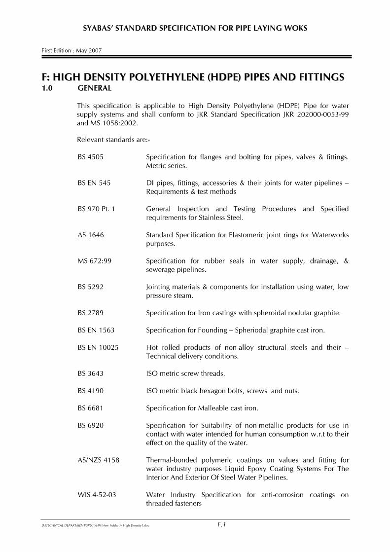
SYABAS’ STANDARD SPECIFICATION FOR PIPE LAYING WOKS First Edition : May 2007 FF:: HHIIGGHH DDEENNSSIITTYY PPOOLLYYEETTHHYYLLEENNEE ((HHDDPPEE)) PPIIPPEESS AANNDD FFIITTTTIINNGGSS 1.0 GENERAL This specification is applicable to High Density Polyethylene (HDPE) Pipe for water
supply systems and shall conform to JKR Standard Specification JKR 202000-0053-99 and MS 1058:2002.
Relevant standards are:-
BS 4505 Specification for flanges and bolting for pipes, valves & fittings.
Metric series. BS EN 545 DI pipes, fittings, accessories & their joints for water pipelines –
Requirements & test methods BS 970 Pt. 1 General Inspection and Testing Procedures and Specified
requirements for Stainless Steel. AS 1646 Standard Specification for Elastomeric joint rings for Waterworks
purposes. MS 672:99 Specification for rubber seals in water supply, drainage, &
sewerage pipelines. BS 5292 Jointing materials & components for installation using water, low
pressure steam. BS 2789 Specification for Iron castings with spheroidal nodular graphite. BS EN 1563 Specification for Founding – Spheriodal graphite cast iron. BS EN 10025 Hot rolled products of non-alloy structural steels and their –
Technical delivery conditions. BS 3643 ISO metric screw threads. BS 4190 ISO metric black hexagon bolts, screws and nuts. BS 6681 Specification for Malleable cast iron. BS 6920 Specification for Suitability of non-metallic products for use in
contact with water intended for human consumption w.r.t to their effect on the quality of the water.
AS/NZS 4158 Thermal-bonded polymeric coatings on values and fitting for
water industry purposes Liquid Epoxy Coating Systems For The Interior And Exterior Of Steel Water Pipelines.
WIS 4-52-03 Water Industry Specification for anti-corrosion coatings on
threaded fasteners
D:\TECHNICAL DEPARTMENT\SPEC YHH\New Folder\F- High Density1.doc F.1
SYABAS’ STANDARD SPECIFICATION FOR PIPE LAYING WOKS First Edition : May 2007
ISO 12162 Thermoplastics materials for pipes and fitting for pressure
applications – Classification and designation – overall service ( design ) coefficient.
ISO 12176-1:98 Plastics pipes and fittings – Equipment for fusion jointing
polyethylene systems – Part 1 : Butt Fusion. EN 712 Thermoplastics piping system – End load – bearing mechanical
joints between pressure pipes and fittings – Test method for resistance to pull – out under constant longitudinal force.
EN 713 Plastics piping system – Mechanical joints between fittings and
polyolefin pressure pipes – Test method for leak tightness under internal pressure whilst subjected to bending.
EN 715 Thermoplastics piping systems – Mechanical and cemented joints
between pressure pipes and fittings – Test method for leak tightness under internal pressure, including end thrust.
EN 921 Thermoplastics pipes – Determination of resistance to internal
pressure at constant temperature. ISO 13953:1995 Polyethylene pipes and fittings – Determination of tensile
strength of test piece from butt fused joint. ISO 13954:1997 Plastics pipes and fittings – Peel de-cohesion test for polyethylene
(PE) electro-fusion assemblies of nominal outside diameter greater than or equal to 90mm.
ISO 13955:1997 Plastics pipes and fittings – Crushing de-cohesion test for
polyethylene (PE) electro-fusion assemblies. ISO 13956:1995 Plastics pipes and fittings – Pull out de-cohesion test for
polyethylene electro-fusion assemblies. 2.0 MATERIAL The High Density Polyethylene (HDPE) Pipe shall be made from base polymer and shall
conform to the requirements as specified in MS 1058 Part 1:2002. The base polymer shall be a single grade of polyethylene, PE 80 with a derived density
greater than 0.93g/cm³ tested at 20° C. No rework material is allowable for the manufacture of the pipes. No additives that may contribute to toxic hazard, impair the fabrication of properties
and chemical and physical properties in particular to long term mechanical and strength is allowed.
3.0 COLOUR
D:\TECHNICAL DEPARTMENT\SPEC YHH\New Folder\F- High Density1.doc F.2
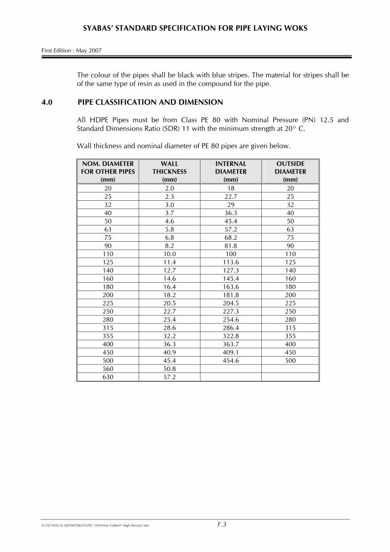
SYABAS’ STANDARD SPECIFICATION FOR PIPE LAYING WOKS First Edition : May 2007 The colour of the pipes shall be black with blue stripes. The material for stripes shall be
of the same type of resin as used in the compound for the pipe. 4.0 PIPE CLASSIFICATION AND DIMENSION All HDPE Pipes must be from Class PE 80 with Nominal Pressure (PN) 12.5 and
Standard Dimensions Ratio (SDR) 11 with the minimum strength at 20° C. Wall thickness and nominal diameter of PE 80 pipes are given below.
NOM. DIAMETER FOR OTHER PIPES
(mm)
WALL THICKNESS
(mm)
INTERNAL DIAMETER
(mm)
OUTSIDE DIAMETER
(mm) 20 2.0 18 20 25 2.3 22.7 25 32 3.0 29 32 40 3.7 36.3 40 50 4.6 45.4 50 63 5.8 57.2 63 75 6.8 68.2 75 90 8.2 81.8 90 110 10.0 100 110 125 11.4 113.6 125 140 12.7 127.3 140 160 14.6 145.4 160 180 16.4 163.6 180 200 18.2 181.8 200 225 20.5 204.5 225 250 22.7 227.3 250 280 25.4 254.6 280 315 28.6 286.4 315 355 32.2 322.8 355 400 36.3 363.7 400 450 40.9 409.1 450 500 45.4 454.6 500 560 50.8 630 57.2
D:\TECHNICAL DEPARTMENT\SPEC YHH\New Folder\F- High Density1.doc F.3
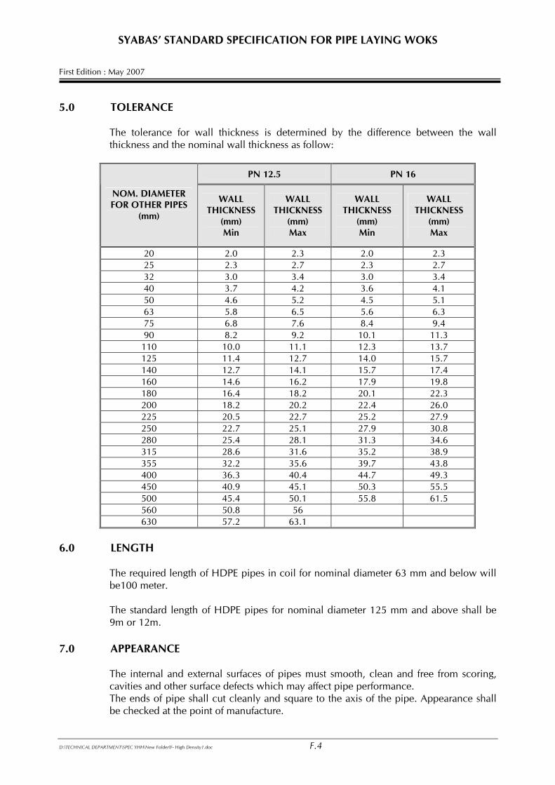
SYABAS’ STANDARD SPECIFICATION FOR PIPE LAYING WOKS First Edition : May 2007 5.0 TOLERANCE The tolerance for wall thickness is determined by the difference between the wall
thickness and the nominal wall thickness as follow:
PN 12.5 PN 16
NOM. DIAMETER FOR OTHER PIPES
(mm)
WALL THICKNESS
(mm) Min
WALL THICKNESS
(mm) Max
WALL THICKNESS
(mm) Min
WALL THICKNESS
(mm) Max
20 2.0 2.3 2.0 2.3 25 2.3 2.7 2.3 2.7 32 3.0 3.4 3.0 3.4 40 3.7 4.2 3.6 4.1 50 4.6 5.2 4.5 5.1 63 5.8 6.5 5.6 6.3 75 6.8 7.6 8.4 9.4 90 8.2 9.2 10.1 11.3 110 10.0 11.1 12.3 13.7 125 11.4 12.7 14.0 15.7 140 12.7 14.1 15.7 17.4 160 14.6 16.2 17.9 19.8 180 16.4 18.2 20.1 22.3 200 18.2 20.2 22.4 26.0 225 20.5 22.7 25.2 27.9 250 22.7 25.1 27.9 30.8 280 25.4 28.1 31.3 34.6 315 28.6 31.6 35.2 38.9 355 32.2 35.6 39.7 43.8 400 36.3 40.4 44.7 49.3 450 40.9 45.1 50.3 55.5 500 45.4 50.1 55.8 61.5 560 50.8 56 630 57.2 63.1
6.0 LENGTH The required length of HDPE pipes in coil for nominal diameter 63 mm and below will
be100 meter. The standard length of HDPE pipes for nominal diameter 125 mm and above shall be
9m or 12m. 7.0 APPEARANCE The internal and external surfaces of pipes must smooth, clean and free from scoring,
cavities and other surface defects which may affect pipe performance. The ends of pipe shall cut cleanly and square to the axis of the pipe. Appearance shall
be checked at the point of manufacture.
D:\TECHNICAL DEPARTMENT\SPEC YHH\New Folder\F- High Density1.doc F.4
SYABAS’ STANDARD SPECIFICATION FOR PIPE LAYING WOKS First Edition : May 2007 8.0 ROUTINE TESTS The pipe suppliers shall, as and when requested by the S.O., furnish results of the
routine tests carried out in accordance with the requirements as stipulated in MS 1058: Part 1 : 2002.
The minimum Oxidation Induction Time (OIT) for pipes fitting shall be 80 min. The
manufacturer must have their own differential Thermal Analyzer or Differential Scanning Calorimeter available for SYABAS’ representatives to carry out the OIT.
9.0 PIPE MARKINGS All pipes must have the following markings:
• Manufacturer’s name or trade mark • Dimensions • Material supplier and material class (PE 80) • Pipe Class (PN) • The word SYABAS (50mm high) in capital letter • SIRIM/IKRAM and QAS Number. • Year of manufacture (last two digits) • Batch production number
10.0 PIPE FITTINGS
10.1 Types of pipe fittings
The following types fittings shall comply to MS 1058 or EN 12201 –3
a) Spigot fittings b) Electro-fusion fittings and c) Mechanical fittings and joints
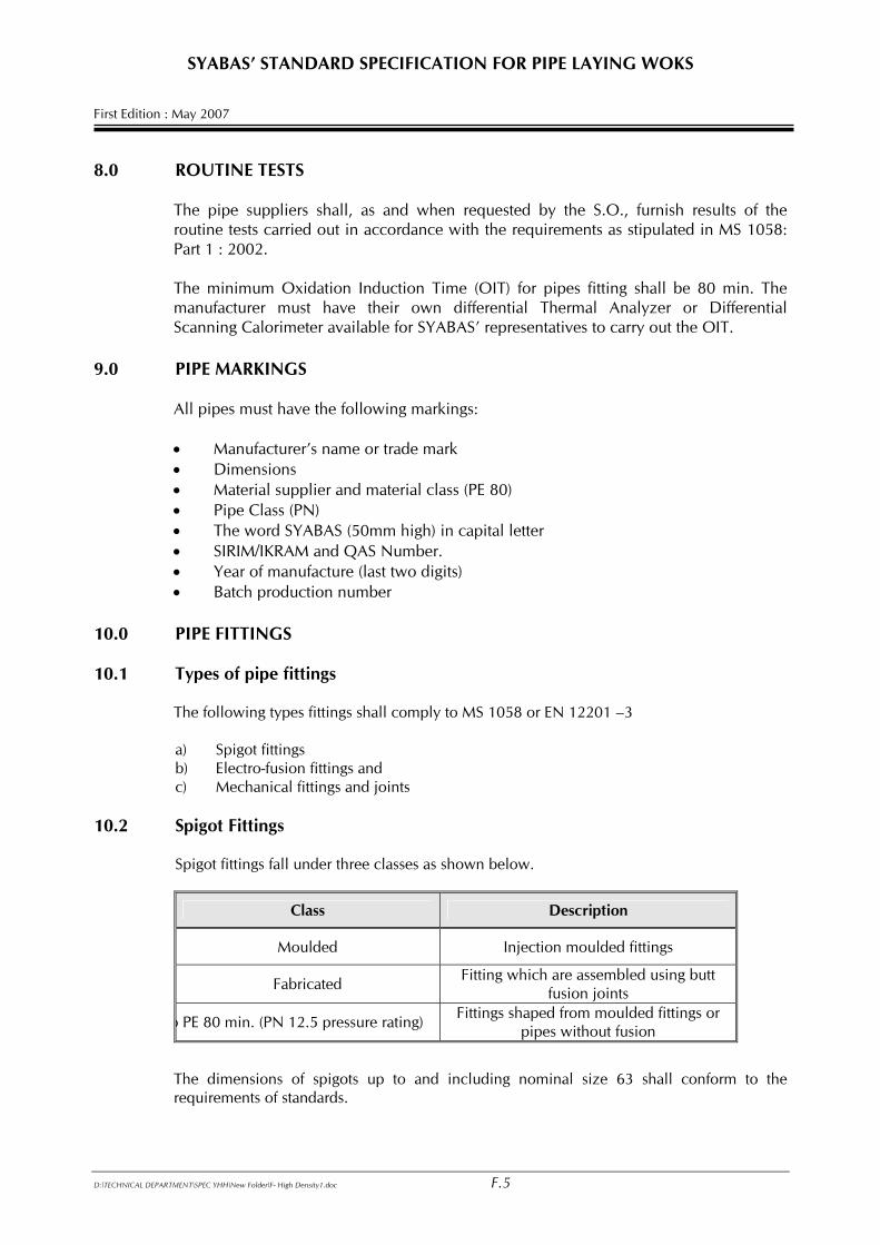
10.2 Spigot Fittings Spigot fittings fall under three classes as shown below.
Class Description
Moulded Injection moulded fittings
Fabricated Fitting which are assembled using butt fusion joints
o PE 80 min. (PN 12.5 pressure rating) Fittings shaped from moulded fittings or pipes without fusion
The dimensions of spigots up to and including nominal size 63 shall conform to the requirements of standards.
D:\TECHNICAL DEPARTMENT\SPEC YHH\New Folder\F- High Density1.doc F.5
SYABAS’ STANDARD SPECIFICATION FOR PIPE LAYING WOKS First Edition : May 2007 10.3 Electro-fusion Fittings Electro-fusion fittings shall be injection moulded fittings made of PE but incorporating
integral heating element(s) to enable fusion jointing with PE pipes. All PE100 fittings shall be jointed by couplers only.
10.4 Mechanical Joints and Fittings
i) General Metal and plastic fittings available for use with PE pipe are:
• Polymeric coated Flanged and other adaptors, • Mechanical type couplers c/w restrainer,
The materials and constituent elements used in making the fitting (including elastomers, greases and any metal parts) shall be as resistant to the external and internal environments as the other elements of the piping system and shall have a life expectancy under the following conditions as least equal to that of the PE pipe conforming to MS 1058 or EN 12201-3 with which they are intended to be used : a) During storage; b) Under the effect of the fluids being conveyed; c) Taking account of the service environment and operating conditions.
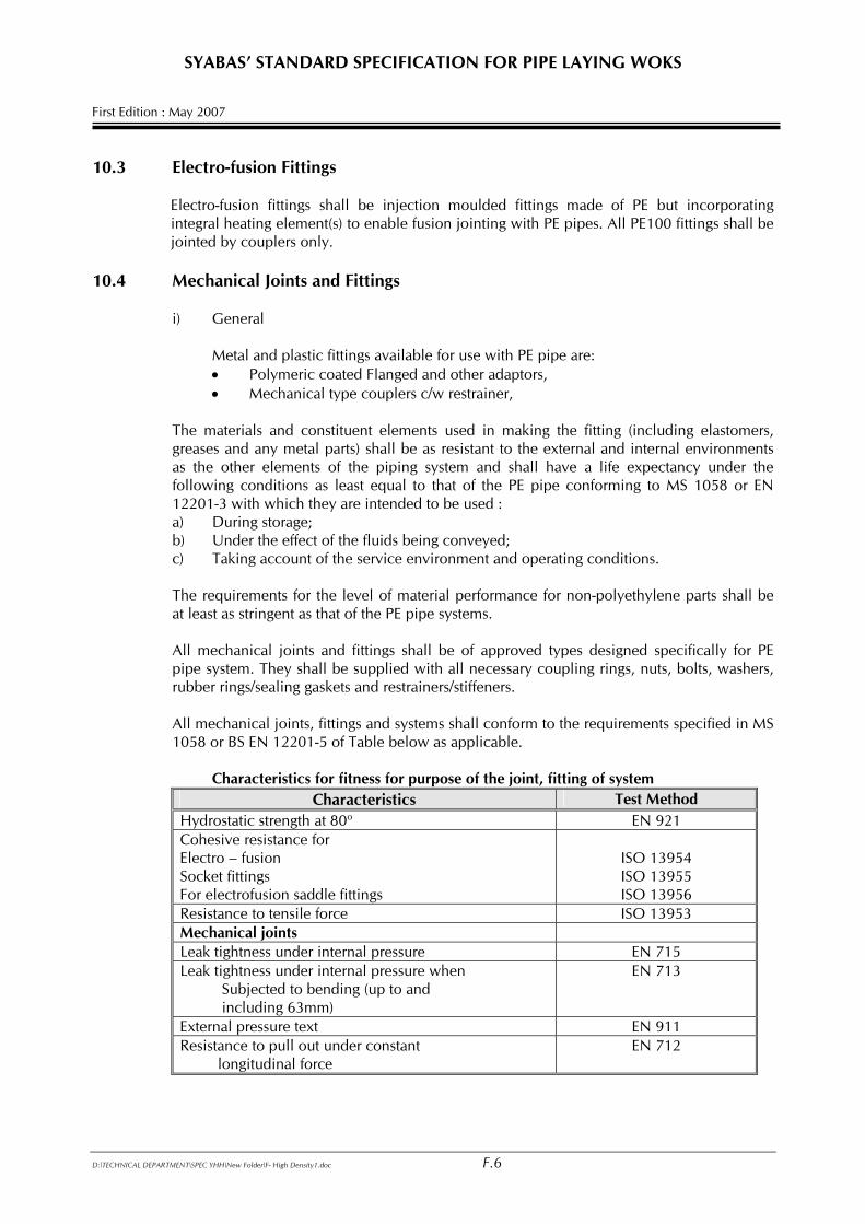
The requirements for the level of material performance for non-polyethylene parts shall be at least as stringent as that of the PE pipe systems. All mechanical joints and fittings shall be of approved types designed specifically for PE pipe system. They shall be supplied with all necessary coupling rings, nuts, bolts, washers, rubber rings/sealing gaskets and restrainers/stiffeners. All mechanical joints, fittings and systems shall conform to the requirements specified in MS 1058 or BS EN 12201-5 of Table below as applicable.
Characteristics for fitness for purpose of the joint, fitting of system
Characteristics Test Method Hydrostatic strength at 80o EN 921 Cohesive resistance for Electro – fusion Socket fittings For electrofusion saddle fittings
ISO 13954 ISO 13955 ISO 13956
Resistance to tensile force ISO 13953 Mechanical joints Leak tightness under internal pressure EN 715 Leak tightness under internal pressure when Subjected to bending (up to and including 63mm)
EN 713
External pressure text EN 911 Resistance to pull out under constant longitudinal force
EN 712
D:\TECHNICAL DEPARTMENT\SPEC YHH\New Folder\F- High Density1.doc F.6
SYABAS’ STANDARD SPECIFICATION FOR PIPE LAYING WOKS First Edition : May 2007
ii) Plastic Parts All fittings/components shall conform to the relevant EN standards. Alternative
standards may be utilized in cases where suitable EN standards do not exist provided a fitness for purpose can be demonstrated.
iii) Metal Parts All metal parts shall be made of ductile iron (BS 2789) of Grade 420/12) or carbon
steel (BS EN 10025 Grade S275, S355JR or BS 4360 43A) or stainless steel (BS970 Part1). No gray cast iron shall be used.
All metal components (except parts made of stainless steel BS 970) of the mechanical
joints and fittings shall undergo the necessary surface preparation for polyamide coating purposes. Bituminous coating is not allowed. Either one of the following polymeric coating is acceptable:
• For coating using either fusion-bonded epoxy powder or polyamide 11 (RISLAN) Bonded Polyamide 11 or not less than 350 µm for Fusion Bonded Epoxy as specified in AS/NZ 4158:1:1994.
• For coating using cold applied high solid liquid epoxy (solvent or solventless)
which meet the requirement of AWWA C210-84, the coating thickness shall not be less than 356 µm.
The metal flanges shall be in accordance with PN 16 in BS 4504 or BS En 1092.
iv) Elastomers The rubber wedge joint rings shall have a hardness range of 66-75 IRHD and shall
meet the requirements as detailed in MS 672-1999 or AS 1646 : 1992 Flange gaskets shall be of flat section minimum 5mm thick (medium grade) (Hardness
60 ± 5 RHD) rubber reinforced with two-ply flexible fabric and complying with BS 5292.
v) Bolts, Nuts and Washers The bolts and nuts shall be hexagonal and shall be in accordance with BS 4190. The
bolts, studs, nuts and washers used shall be made of stainless steel or hot-dipped galvanized carbon steel coated with fusion bonded epoxy powder or polyamide 11 to the finished thickness of coating between 75µm and 125µm according to WIS 4 – 52 –03 –1994. Cold applied high solid epoxy shall be used to repair the damaged coatings on the bolts and nuts after fastening.
vi) Effect on water quality When used under condition for which they are designed, materials used for fittings
intended for the conveyance of water for human consumption shall comply with BS 6920.
D:\TECHNICAL DEPARTMENT\SPEC YHH\New Folder\F- High Density1.doc F.7
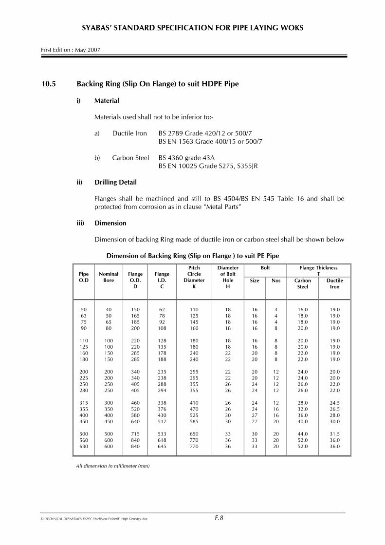
SYABAS’ STANDARD SPECIFICATION FOR PIPE LAYING WOKS First Edition : May 2007 10.5 Backing Ring (Slip On Flange) to suit HDPE Pipe
i) Material
Materials used shall not to be inferior to:-
a) Ductile Iron BS 2789 Grade 420/12 or 500/7 BS EN 1563 Grade 400/15 or 500/7 b) Carbon Steel BS 4360 grade 43A BS EN 10025 Grade S275, S355JR
ii) Drilling Detail Flanges shall be machined and still to BS 4504/BS EN 545 Table 16 and shall be
protected from corrosion as in clause “Metal Parts” iii) Dimension Dimension of backing Ring made of ductile iron or carbon steel shall be shown below
Dimension of Backing Ring (Slip on Flange ) to suit PE Pipe
Bolt Flange Thickness T
Pipe O.D
Nominal
Bore
Flange O.D.
D
Flange
I.D. C
Pitch Circle
Diameter K
Diameter of Bolt Hole
H Size Nos Carbon
Steel Ductile
Iron
50 63 75 90
110 125 160 180
200 225 250 280
315 355 400 450
500 560 630
40 50 65 80
100 100 150 150
200 200 250 250
300 350 400 450
500 600 600
150 165 185 200
220 220 285 285
340 340 405 405
460 520 580 640
715 840 840
62 78 92
108
128 135 178 188
235 238 288 294
338 376 430 517
533 618 645
110 125 145 160
180 180 240 240
295 295 355 355
410 470 525 585
650 770 770
18 18 18 18
18 18 22 22
22 22 26 26
26 26 30 30
33 36 36
16 16 16 16
16 16 20 20
20 20 24 24
24 24 27 27
30 33 33
4 4 4 8
8 8 8 8
12 12 12 12
12 16 16 20
20 20 20
16.0 18.0 18.0 20.0
20.0 20.0 22.0 22.0
24.0 24.0 26.0 26.0
28.0 32.0 36.0 40.0
44.0 52.0 52.0
19.0 19.0 19.0 19.0
19.0 19.0 19.0 19.0
20.0 20.0 22.0 22.0
24.5 26.5 28.0 30.0
31.5 36.0 36.0
All dimension in millimeter (mm)
D:\TECHNICAL DEPARTMENT\SPEC YHH\New Folder\F- High Density1.doc F.8
SYABAS’ STANDARD SPECIFICATION FOR PIPE LAYING WOKS First Edition : May 2007
iv) Workmanship
a) All casting shall be homogenous, smooth and shall be free from flaws, cracks, blowholes, cuts or other harmful defects. All surfaces in close proximity to the pipe shall be smooth and free from sharp edges.
b) All steel flanges cut from plate shall have their surfaces machine finished and
shall be free from surface defects. 10.6 Storage 10.6.1 Storage at Depot All materials should be carefully inspected at the time of delivery and any defective material
set-aside before accepting the delivery into stores. The defective materials should be return to the suppliers immediately.
Pipes and fittings should be used in the order of delivery to ensure the correct rotation of stock.
All pipe stacks should be made on sufficiently firm, flat ground to support the weight of the
pipes and any necessary lifting equipment. Stacking heights should generally be kept to a minimum and adequate space allocated for lifting machinery to manoeuvre without causing accidental damage.
For safety and convenience of handling the stacking height of bundles should not be more
than 3m. To prevent possible deformation of the pipes, bundles must be stored timber to timber.
For similar reasons, pipe coils should be stored flat and the number of coils per stack should be limited to:
• 7 coils for 20mm pipe • 6 coils for 25mm pipe • 5 coils for 32mm pipe • 4 coils for 50mm pipe • 3 coils for 63mm pipe • 2 coils for 90mm pipe • 1 coils for 110, 125 and 180 pipes.
Where individual pipe lengths are stacked in pyramidal fashion, deformation may occur in
the lower layers. Such stacks should therefore be not greater than 1m high. Electro-fusion and compression fittings should be stored under cover, preferably on racking
and in the manufacturer’s protective wrapping or cartons which should be kept intact until the fitting is required for use except spigot fittings.
At all times pipes and fittings should be stored away from exhaust outlets and all other high
temperature sources. Care should also be taken to avoid contact with lubricating or hydraulic oils, gasoline, solvents and other aggressive chemicals.
All special tool and equipment associated with the jointing of pipes and fittings should be
stored separately and securely until they are required for use.
D:\TECHNICAL DEPARTMENT\SPEC YHH\New Folder\F- High Density1.doc F.9
SYABAS’ STANDARD SPECIFICATION FOR PIPE LAYING WOKS First Edition : May 2007 10.6.2 Storage on Site All pipe store locations should be on suitably firm, level ground, free from damaging
material with adequate access for construction vehicles and/or lifting equipment. In all storage sites, careful consideration should be given to the following aspects:
• Security of all materials and equipment from theft, vandalism, accidental damage or contamination.
• Safety of pedestrians. • The movement of traffic and construction equipment
When stringing is adopted, pipes should be placed well clear of the excavators and away
from excavated material area. They should be wedged to prevent accidental movement. Where necessary protective barriers complete with adequate warning signs and lights should be erected.
11.0 PRE – DELIVERY INSPECTION AND EVALUATION It is the responsibility of the supplier to inform SYABAS for inspection purposes during
manufacturing and before delivery. SYABAS reserved the right to inspect and witness the testing of product offered. If the
product fails the mandatory test, the manufacturer will be notified and a second cut section will be tested. If the second cut section fails, the product will be rejected from use in the state.
At any time, when requested, the supplier is to provide SYABAS a sample of the product
offered for evaluation purposes. All costs shall be borne by the supplier. If at any time the supplier fails to deliver the required sample, the product is deemed to
have failed to meet the specifications and the product will not be further used in the project..
12.0 HANDLING, TRANSPORT AND STORAGE 12.1 General Polyethylene pipes are characterized by being tough and resilient and are relatively light.
Though it is easy to handle, they are prone to damage by scoring by sharp objects. Therefore, careful handling is always required and the dragging of straight pipes and coils should be avoided whenever possible.
The maximum allowance depth of scoring of the external surface of the pipe is 5% of the
wall thickness. Pipes and fittings showing obvious defects, excessive scoring or sharp deep cut even if less than 5% of the wall thickness should be withdrawn and returned to the suppliers.
Pipes up to 125mm are usually supplied and delivered loose or strapped into convenient bundles or banded coils. Fittings are normally supplied in separate bags or cartons/pallets.
D:\TECHNICAL DEPARTMENT\SPEC YHH\New Folder\F- High Density1.doc F.10
SYABAS’ STANDARD SPECIFICATION FOR PIPE LAYING WOKS First Edition : May 2007 12.2 Transport and Delivery For transporting bulk loads the vehicles should be provided with a clean flat bed, free from
nails or other projections which may cause damage. Care should be taken to avoid positioning pipes and fittings near or adjacent to exhaust
systems or other heat sources as after as possible, avoid contamination from materials such as diesel oil.
Straight pipes should be fully supported or bound together. Metal chains or slings should not be brought into direct contact with the pipe. Webbed sling
of polyethylene or nylon are recommended. When transporting pipes of different sizes, pipes of higher-pressure class shall be loaded
underneath. If the pipes are transported one inside another, the smaller pipes shall be removed first and piled separately.
Both vertical and horizontal deliveries of coiled pipes are permissible. 12.3 Off Loading 12.3.1 Bundled Pipes When lifting by crane, non-metallic wide band slings or ropes should be used. For pipe
length greater than 6m, load spreading bars of a length at least equivalent to one quarter of the length of the pipe or bundlepack should be employed.
Chains or end hooks should not be used. Care should be taken to avoid damage to pipes
and pipe ends during lifting. Some bending should be allowed for in the middle of the lift when loading and unloading
pipes. However to avoid excess bending, lifting points should always be well and evenly spaced.
Six meters long bundlepacks may be handled by fork lift trucks but the positioning of the
forks shall cause minimum bending of the pipes. Bundlepacks longer than 6m long should be handled either by side loader with a minimum
of four supporting forks, or by a crane using a spreader beam and suitable slings. Off loading on site may be made easier by using skid timbers and rope slings.
12.3.2 Coiled Pipes Coils of pipes can be handled by fork lift truck. Where individual coils are too heavy for
manual lifting, a fork lift truck with suitable protected boom attachments should be used. They should NOT be rolled off the edge of loading platforms or trailers.
Complete coils are secured by outer and intermediate bands and individual layers are also
independently secures. Plastic tape at least 10mm wide should be used for banding.
D:\TECHNICAL DEPARTMENT\SPEC YHH\New Folder\F- High Density1.doc F.11
SYABAS’ STANDARD SPECIFICATION FOR PIPE LAYING WOKS First Edition : May 2007 The bands should not be removed until the pipe is required for use. The bands securing the
outer end of the pipe should be removed first and the movement of the free end carefully controlled. This should be followed by those securing successive layers, and only those bands necessary to release the length of pipe immediately required should be cut and removed.
When removed from the coil or drum, the pipe will be oval and curved. Although both
ovality and curvature will reduce with time, special tools are available a facilitate handing and jointing.
12.3.3 Fittings Hocks should not be used to lift fittings which are generally supplied with cardboard boxes.
Special care should be taken in the handing of “pup” fittings to ensure that the weight of the fittings is not transferred to the fabricated joint.
13.0 CERTIFICATION Manufacturer or supplier is requirement to provide a copy of the certificate and test
report either from SIRIM, IKRAM or other recognised certification body. Test reports should be those tests conducted within a year period. SYABAS reserved the right to refuse offer or reject supply if the necessary documents are
not enclosed. 14.0 HDPE PIPE JOINTING Pipe joining for pipes buried underground, below pavement or slab or concealed in slab
shall use electro-fusion or fully automatic butt fusion jointing unless instructed otherwise by S.O.
15.0 JOINTING BY BUTT FUSION 15.1 General Butt fusion is process of welding HDPE pipes and fittings using an electrically heated
plate. It is suitable for jointing HDPE pipes and fittings of size from 110 : OD and above. However, only pipes and fittings of the same material type, size and rating shall be butt welded, e.g. PE 100 pipes should not currently be welded to PE 80 pipes. PN 10 pipe should not be welded to PN 6 pipe or fitting.
The following table shows the recommended conditions.
D:\TECHNICAL DEPARTMENT\SPEC YHH\New Folder\F- High Density1.doc F.12
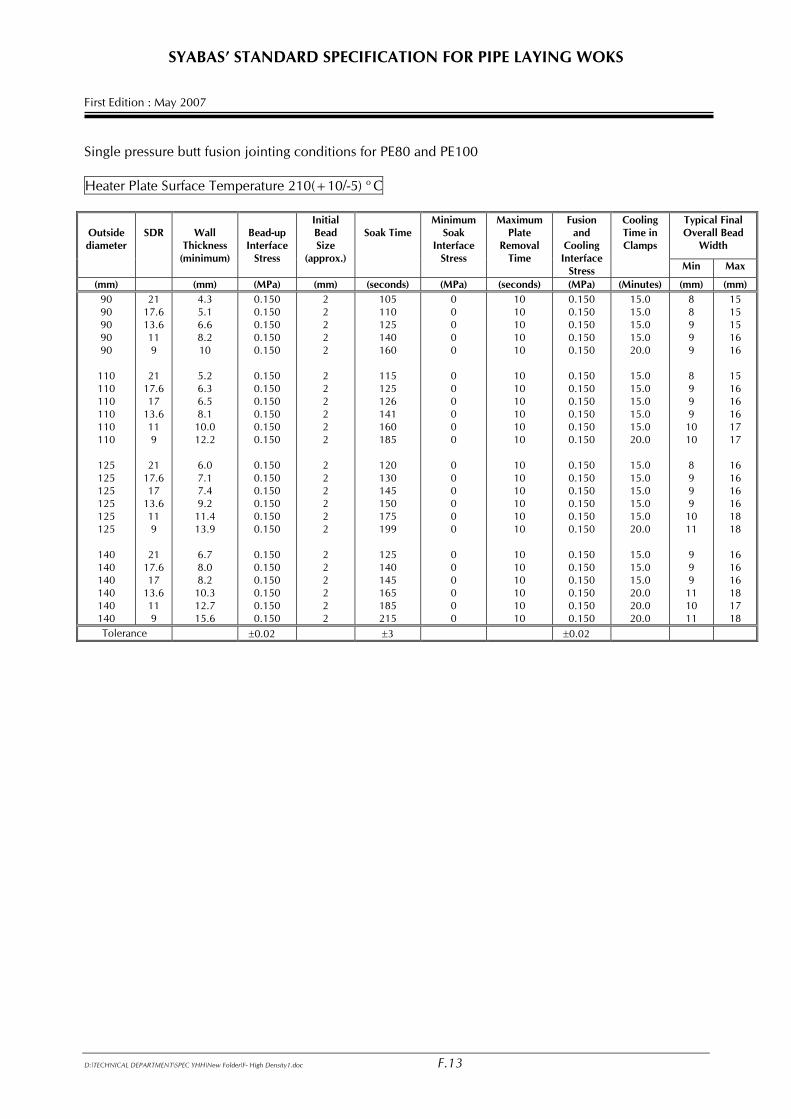
SYABAS’ STANDARD SPECIFICATION FOR PIPE LAYING WOKS First Edition : May 2007 Single pressure butt fusion jointing conditions for PE80 and PE100 Heater Plate Surface Temperature 210(+10/-5) o C
Typical Final Overall Bead
Width
Outside diameter
SDR
Wall
Thickness (minimum)
Bead-up Interface
Stress
Initial Bead Size
(approx.)
Soak Time
Minimum Soak
Interface Stress
Maximum Plate
Removal Time
Fusion and
Cooling Interface
Stress
Cooling Time in Clamps
Min Max
(mm) (mm) (MPa) (mm) (seconds) (MPa) (seconds) (MPa) (Minutes) (mm) (mm) 90 90 90 90 90
110 110 110 110 110 110
125 125 125 125 125 125
140 140 140 140 140 140
21 17.6 13.6 11 9
21 17.6 17
13.6 11 9
21 17.6 17
13.6 11 9
21 17.6 17
13.6 11 9
4.3 5.1 6.6 8.2 10
5.2 6.3 6.5 8.1
10.0 12.2
6.0 7.1 7.4 9.2
11.4 13.9
6.7 8.0 8.2
10.3 12.7 15.6
0.150 0.150 0.150 0.150 0.150
0.150 0.150 0.150 0.150 0.150 0.150
0.150 0.150 0.150 0.150 0.150 0.150
0.150 0.150 0.150 0.150 0.150 0.150
2 2 2 2 2
2 2 2 2 2 2
2 2 2 2 2 2
2 2 2 2 2 2
105 110 125 140 160
115 125 126 141 160 185
120 130 145 150 175 199
125 140 145 165 185 215
0 0 0 0 0
0 0 0 0 0 0
0 0 0 0 0 0
0 0 0 0 0 0
10 10 10 10 10
10 10 10 10 10 10
10 10 10 10 10 10
10 10 10 10 10 10
0.150 0.150 0.150 0.150 0.150
0.150 0.150 0.150 0.150 0.150 0.150
0.150 0.150 0.150 0.150 0.150 0.150
0.150 0.150 0.150 0.150 0.150 0.150
15.0 15.0 15.0 15.0 20.0
15.0 15.0 15.0 15.0 15.0 20.0
15.0 15.0 15.0 15.0 15.0 20.0
15.0 15.0 15.0 20.0 20.0 20.0
8 8 9 9 9
8 9 9 9
10 10
8 9 9 9
10 11
9 9 9
11 10 11
15 15 15 16 16
15 16 16 16 17 17
16 16 16 16 18 18
16 16 16 18 17 18
Tolerance ±0.02 ±3 ±0.02
D:\TECHNICAL DEPARTMENT\SPEC YHH\New Folder\F- High Density1.doc F.13
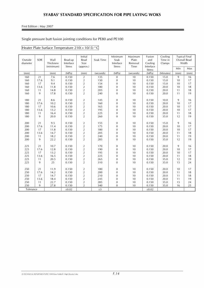
SYABAS’ STANDARD SPECIFICATION FOR PIPE LAYING WOKS First Edition : May 2007 Single pressure butt fusion jointing conditions for PE80 and PE100 Heater Plate Surface Temperature 210(+10/-5) o C
Typical Final Overall Bead
Width
Outside diameter
SDR
Wall
Thickness (minimum)
Bead-up Interface
Stress
Initial Bead Size
(approx.)
Soak Time
Minimum Soak
Interface Stress
Maximum Plate
Removal Time
Fusion and
Cooling Interface
Stress
Cooling Time in Clamps
Min Max
(mm) (mm) (MPa) (mm) (seconds) (MPa) (seconds) (MPa) (Minutes) (mm) (mm) 160 160 160 160 160 160
180 180 180 180 180 180
200 200 200 200 200 200
225 225 225 225 225 225
250 250 250 250 250 250
21 17.6 17
13.6 11 9
21 17.6 17
13.6 11 9
21 17.6 17
13.6 11 9
21 17.6 17
13.6 11 9
21 17.6 17
13.6 11 9
7.6 9.1 9.4
11.8 14.8 17.8
8.6
10.2 10.6 13.2 16.4 20.0
9.5
11.4 11.8 14.7 18.2 22.2
10.7 12.8 13.2 16.5 20.5 25
11.9 14.2 14.7 18.4 22.7 27.8
0.150 0.150 0.150 0.150 0.150 0.150
0.150 0.150 0.150 0.150 0.150 0.150
0.150 0.150 0.150 0.150 0.150 0.150
0.150 0.150 0.150 0.150 0.150 0.150
0.150 0.150 0.150 0.150 0.150 0.150
2 2 2 2 2 2
2 2 2 2 2 2
2 2 2 2 2 2
2 2 2 2 2 2
2 2 2 2 2 2
135 150 154 180 205 240
145 160 165 195 225 260
155 175 180 205 240 285
170 190 195 225 265 310
180 200 210 245 285 340
0 0 0 0 0 0
0 0 0 0 0 0
0 0 0 0 0 0
0 0 0 0 0 0
0 0 0 0 0 0
10 10 10 10 10 10
10 10 10 10 10 10
10 10 10 10 10 10
10 10 10 10 10 10
10 10 10 10 10 10
0.150 0.150 0.150 0.150 0.150 0.150
0.150 0.150 0.150 0.150 0.150 0.150
0.150 0.150 0.150 0.150 0.150 0.150
0.150 0.150 0.150 0.150 0.150 0.150
0.150 0.150 0.150 0.150 0.150 0.150
15.0 15.0 15.0 20.0 20.0 20.0
10.0 20.0 20.0 20.0 20.0 35.0
15.0 20.0 20.0 20.0 20.0 35.0
20.0 20.0 20.0 20.0 35.0 35.0
20.0 20.0 20.0 20.0 35.0 35.0
9 10 10 10 11 11
9
10 10 10 11 12
9
10 10 11 11 12
9
10 10 11 12 15
10 11 11 11 15 16
16 17 17 18 18 19
16 17 17 17 18 19
16 17 17 18 19 19
16 17 17 18 19 24
17 18 18 19 24 25
Tolerance ±0.02 ±3 ±0.02
D:\TECHNICAL DEPARTMENT\SPEC YHH\New Folder\F- High Density1.doc F.14
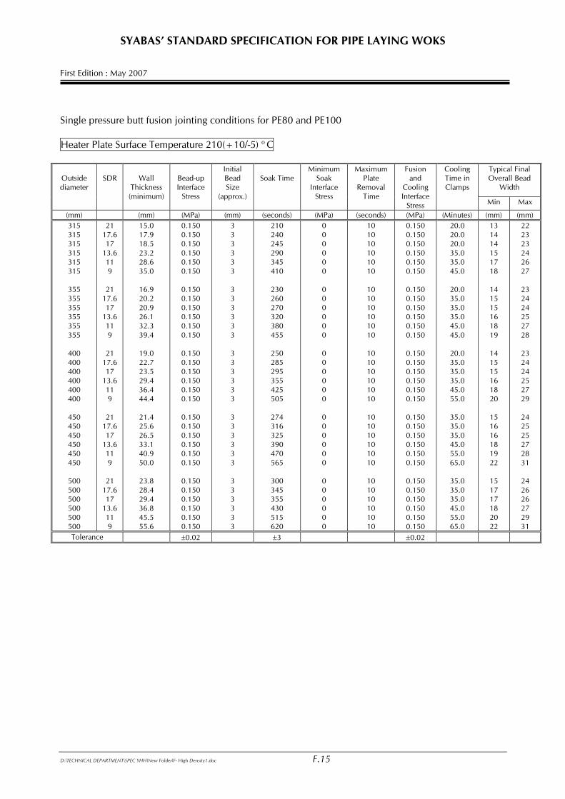
SYABAS’ STANDARD SPECIFICATION FOR PIPE LAYING WOKS First Edition : May 2007 Single pressure butt fusion jointing conditions for PE80 and PE100 Heater Plate Surface Temperature 210(+10/-5) o C
Typical Final Overall Bead
Width
Outside diameter
SDR
Wall
Thickness (minimum)
Bead-up Interface
Stress
Initial Bead Size
(approx.)
Soak Time
Minimum Soak
Interface Stress
Maximum Plate
Removal Time
Fusion and
Cooling Interface
Stress
Cooling Time in Clamps
Min Max
(mm) (mm) (MPa) (mm) (seconds) (MPa) (seconds) (MPa) (Minutes) (mm) (mm) 315 315 315 315 315 315
355 355 355 355 355 355
400 400 400 400 400 400
450 450 450 450 450 450
500 500 500 500 500 500
21 17.6 17
13.6 11 9
21 17.6 17
13.6 11 9
21 17.6 17
13.6 11 9
21 17.6 17
13.6 11 9
21 17.6 17
13.6 11 9
15.0 17.9 18.5 23.2 28.6 35.0
16.9 20.2 20.9 26.1 32.3 39.4
19.0 22.7 23.5 29.4 36.4 44.4
21.4 25.6 26.5 33.1 40.9 50.0
23.8 28.4 29.4 36.8 45.5 55.6
0.150 0.150 0.150 0.150 0.150 0.150
0.150 0.150 0.150 0.150 0.150 0.150
0.150 0.150 0.150 0.150 0.150 0.150
0.150 0.150 0.150 0.150 0.150 0.150
0.150 0.150 0.150 0.150 0.150 0.150
3 3 3 3 3 3
3 3 3 3 3 3
3 3 3 3 3 3
3 3 3 3 3 3
3 3 3 3 3 3
210 240 245 290 345 410
230 260 270 320 380 455
250 285 295 355 425 505
274 316 325 390 470 565
300 345 355 430 515 620
0 0 0 0 0 0
0 0 0 0 0 0
0 0 0 0 0 0
0 0 0 0 0 0
0 0 0 0 0 0
10 10 10 10 10 10
10 10 10 10 10 10
10 10 10 10 10 10
10 10 10 10 10 10
10 10 10 10 10 10
0.150 0.150 0.150 0.150 0.150 0.150
0.150 0.150 0.150 0.150 0.150 0.150
0.150 0.150 0.150 0.150 0.150 0.150
0.150 0.150 0.150 0.150 0.150 0.150
0.150 0.150 0.150 0.150 0.150 0.150
20.0 20.0 20.0 35.0 35.0 45.0
20.0 35.0 35.0 35.0 45.0 45.0
20.0 35.0 35.0 35.0 45.0 55.0
35.0 35.0 35.0 45.0 55.0 65.0
35.0 35.0 35.0 45.0 55.0 65.0
13 14 14 15 17 18
14 15 15 16 18 19
14 15 15 16 18 20
15 16 16 18 19 22
15 17 17 18 20 22
22 23 23 24 26 27
23 24 24 25 27 28
23 24 24 25 27 29
24 25 25 27 28 31
24 26 26 27 29 31
Tolerance ±0.02 ±3 ±0.02
D:\TECHNICAL DEPARTMENT\SPEC YHH\New Folder\F- High Density1.doc F.15
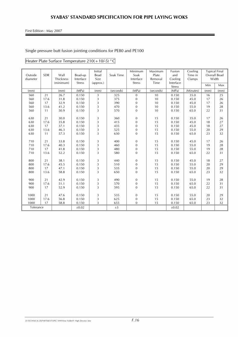
SYABAS’ STANDARD SPECIFICATION FOR PIPE LAYING WOKS First Edition : May 2007 Single pressure butt fusion jointing conditions for PE80 and PE100 Heater Plate Surface Temperature 210(+10/-5) o C
Typical Final Overall Bead
Width
Outside diameter
SDR
Wall
Thickness (minimum)
Bead-up Interface
Stress
Initial Bead Size
(approx.)
Soak Time
Minimum Soak
Interface Stress
Maximum Plate
Removal Time
Fusion and
Cooling Interface
Stress
Cooling Time in Clamps
Min Max
(mm) (mm) (MPa) (mm) (seconds) (MPa) (seconds) (MPa) (Minutes) (mm) (mm) 560 560 560 560 560
630 630 630 630 630
710 710 710 710
800 800 800 800
900 900 900
1000 1000 1000
21 17.6 17
13.6 11
21
17.6 17
13.6 11
21
17.6 17
13.6
21 17.6 17
13.6
21 17.6 17
21
17.6 17
26.7 31.8 32.9 41.2 50.9
30.0 35.8 37.1 46.3 57.3
33.8 40.3 41.8 52.2
38.1 45.5 47.1 58.8
42.9 51.1 52.9
47.6 56.8 58.8
0.150 0.150 0.150 0.150 0.150
0.150 0.150 0.150 0.150 0.150
0.150 0.150 0.150 0.150
0.150 0.150 0.150 0.150
0.150 0.150 0.150
0.150 0.150 0.150
3 3 3 3 3
3 3 3 3 3
3 3 3 3
3 3 3 3
3 3 3
3 3 3
325 375 390 470 570
360 415 435 525 630
400 460 480 580
440 510 535 650
490 570 595
535 625 655
0 0 0 0 0
0 0 0 0 0
0 0 0 0
0 0 0 0
0 0 0
0 0 0
10 10 10 10 10
15 15 15 15 15
15 15 15 15
15 15 15 15
15 15 15
15 15 15
0.150 0.150 0.150 0.150 0.150
0.150 0.150 0.150 0.150 0.150
0.150 0.150 0.150 0.150
0.150 0.150 0.150 0.150
0.150 0.150 0.150
0.150 0.150 0.150
35.0 45.0 45.0 55.0 65.0
35.0 45.0 45.0 55.0 65.0
45.0 55.0 55.0 65.0
45.0 55.0 55.0 65.0
55.0 65.0 65.0
55.0 65.0 65.0
16 17 17 19 22
17 18 18 20 23
17 19 19 22
18 20 20 23
19 22 22
20 23 23
25 26 26 28 31
26 27 27 29 32
26 28 28 31
27 29 29 32
28 31 31
29 32 32
Tolerance ±0.02 ±3 ±0.02
D:\TECHNICAL DEPARTMENT\SPEC YHH\New Folder\F- High Density1.doc F.16
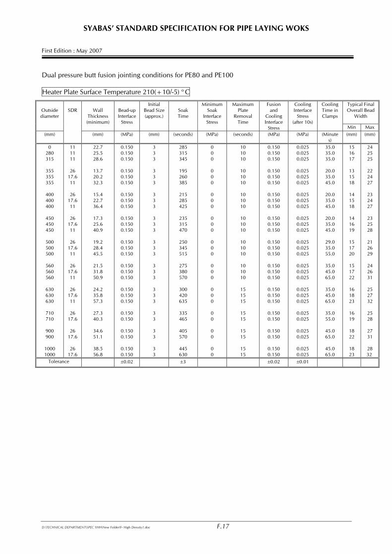
SYABAS’ STANDARD SPECIFICATION FOR PIPE LAYING WOKS First Edition : May 2007 Dual pressure butt fusion jointing conditions for PE80 and PE100 Heater Plate Surface Temperature 210(+10/-5) o C
Typical Final Overall Bead
Width
Outside diameter
Wall
Thickness (minimum)
Bead-up Interface
Stress
Initial Bead Size (approx.)
Soak Time
Minimum Soak
Interface Stress
Maximum Plate
Removal Time
Fusion and
Cooling Interface
Stress
Cooling Interface
Stress (after 10s)
Cooling Time in Clamps
Min Max (mm)
SDR
(mm) (MPa) (mm) (seconds) (MPa) (seconds) (MPa) (MPa) (Minutes)
(mm) (mm)
0 280 315
355 355 355
400 400 400
450 450 450
500 500 500
560 560 560
630 630 630
710 710
900 900
1000 1000
11 11 11
26
17.6 11
26
17.6 11
26
17.6 11
26
17.6 11
26
17.6 11
26
17.6 11
26
17.6
26 17.6
26
17.6
22.7 25.5 28.6
13.7 20.2 32.3
15.4 22.7 36.4
17.3 25.6 40.9
19.2 28.4 45.5
21.5 31.8 50.9
24.2 35.8 57.3
27.3 40.3
34.6 51.1
38.5 56.8
0.150 0.150 0.150
0.150 0.150 0.150
0.150 0.150 0.150
0.150 0.150 0.150
0.150 0.150 0.150
0.150 0.150 0.150
0.150 0.150 0.150
0.150 0.150
0.150 0.150
0.150 0.150
3 3 3 3 3 3 3 3 3 3 3 3 3 3 3 3 3 3 3 3 3 3 3 3 3 3 3
285 315 345
195 260 385
215 285 425
235 315 470
250 345 515
275 380 570
300 420 635
335 465
405 570
445 630
0 0 0 0 0 0 0 0 0 0 0 0 0 0 0 0 0 0 0 0 0 0 0 0 0 0 0
10 10 10
10 10 10
10 10 10
10 10 10
10 10 10
10 10 10
15 15 15
15 15
15 15
15 15
0.150 0.150 0.150
0.150 0.150 0.150
0.150 0.150 0.150
0.150 0.150 0.150
0.150 0.150 0.150
0.150 0.150 0.150
0.150 0.150 0.150
0.150 0.150
0.150 0.150
0.150 0.150
0.025 0.025 0.025
0.025 0.025 0.025
0.025 0.025 0.025
0.025 0.025 0.025
0.025 0.025 0.025
0.025 0.025 0.025
0.025 0.025 0.025
0.025 0.025
0.025 0.025
0.025 0.025
35.0 35.0 35.0
20.0 35.0 45.0
20.0 35.0 45.0
20.0 35.0 45.0
29.0 35.0 55.0
35.0 45.0 65.0
35.0 45.0 65.0
35.0 55.0
45.0 65.0
45.0 65.0
15 16 17
13 15 18
14 15 18
14 16 19
15 17 20
15 17 22
16 18 23
16 19
18 22
18 23
24 25 25
22 24 27
23 24 27
23 25 28
21 26 29
24 26 31
25 27 32
25 28
27 31
28 32
Tolerance ±0.02 ±3 ±0.02 ±0.01
D:\TECHNICAL DEPARTMENT\SPEC YHH\New Folder\F- High Density1.doc F.17
SYABAS’ STANDARD SPECIFICATION FOR PIPE LAYING WOKS First Edition : May 2007 15.2 Butt Fusion Jointing Equipment Butt fusion jointing equipment shall be certified in accordance with MS 1058 or ISO
12176-1. Only fully automatic Computerized Numerical Control (CNC) machines or computerized microprocessor based machines shall be used. Manual or Semi Automatic CNC machines are NOT allowed.
a) Chassis and Clamps The machine shall have a frame containing clamps which are sufficiently robust to
re-round and accurately align the pipes to be jointed. The machine shall have a minimum of two rams mounted on the pie center-line
axis. The ram shall move freely and control the movement of any sliding clamps. All slides shall be kept free from rust and lubricated at all times.
b) Hydraulic/pneumatic unit The unit shall be capable of actuating the clamp unit to provide adequate force
and speed of operation. A pressure monitoring device shall be provided to monitor ram pressure.
UUnnlleessss aann aauuttoommaattiicc mmaacchhiinnee iiss uusseedd,, aa ddaattaa ppllaattee ppeerrmmaanneennttllyy aattttaacchheedd ttoo tthhee uunniitt
sseettttiinngg oouutt jjooiinnttiinngg aanndd ccoooolliinngg pprreessssuurreess aanndd ttiimmeess ffoorr ssppeecciiffiieedd ssiizzeess ooff ppiippee.. NNoottee :: IItt iiss vveerryy iimmppoorrttaanntt tthhaatt wweellddiinngg mmaacchhiinnee ccaann ccoonnttrrooll tthhee sseeccoonnddaarryy pprreessssuurreess
aaccccuurraatteellyy aass tthheessee wwiillll ssoommeettiimmeess bbee oonnllyy sslliigghhttllyy ggrreeaatteerr tthhaann tthhee ddrraagg pprreessssuurree..
(c) Trimming tool The trimming tool shall be capable of being mounted securely within the frame of
the jointing machine, so that this equipment can produce accurately matched planed faces.
Trimming blades of the planer shall be sharp and have defect free cutting edges to
provide continuous swarf of uniform thickness. (d) Heater Plate The plate shall be electrically heated and shall be provided with a suitable
temperature controller to give a uniform surface temperature of 210 (+10 / –5) oC.
The plate surface shall have a permanent coat of anti-stick material. ADDITIONAL
SPRAY-ON RELEASE AGENTS SHALL NOT BE USED. The surface shall be free from any contaminants.
The plate shall be fitted with an accurate temperature probe or indicator, accurate
to within ± 2 oC in the range of 200o – 240oC. The temperature on both sides of the circumference shall be measured using a digital thermometer with an appropriate surface probe.
(e) Control system
D:\TECHNICAL DEPARTMENT\SPEC YHH\New Folder\F- High Density1.doc F.18
SYABAS’ STANDARD SPECIFICATION FOR PIPE LAYING WOKS First Edition : May 2007
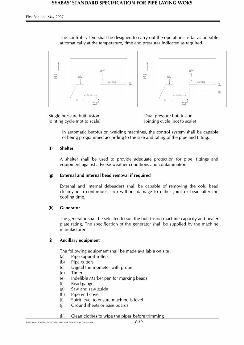
The control system shall be designed to carry out the operations as far as possible
automatically at the temperature, time and pressures indicated as required.
COOLING TIME
bead rollover
Initial bead-up
Heat Soak
Interface stress (MP a)
Heater plate removal
COOLING TIME
bead roll over
Initialbead-up
Heat Soak
Interfacestress(MP a)
Heater plate removal
0.15MP a
Time Time
0.15MP a
0.025MP a
Single pressure butt fusion Dual pressure butt fusion Jointing cycle (not to scale) Jointing cycle (not to scale) In automatic butt-fusion welding machines, the control system shall be capable
of being programmed according to the size and rating of the pipe and fitting.
(f) Shelter A shelter shall be used to provide adequate protection for pipe, fittings and
equipment against adverse weather conditions and contamination. (g) External and internal bead removal if required External and internal debeaders shall be capable of removing the cold bead
cleanly in a continuous strip without damage to either joint or bead after the cooling time.
(h) Generator The generator shall be selected to suit the butt fusion machine capacity and heater
plate rating. The specification of the generator shall be supplied by the machine manufacturer
(i) Ancillary equipment The following equipment shall be made available on site :
(a) Pipe support rollers (b) Pipe cutters (c) Digital thermometer with probe (d) Timer (e) Indelible Marker pen for marking beads (f) Bead gauge (g) Saw and saw guide (h) Pipe end cover (i) Spirit level to ensure machine is level (j) Ground sheets or base boards
(k) Clean clothes to wipe the pipes before trimming
D:\TECHNICAL DEPARTMENT\SPEC YHH\New Folder\F- High Density1.doc F.19
SYABAS’ STANDARD SPECIFICATION FOR PIPE LAYING WOKS First Edition : May 2007 15.2.1 Butt Fusion Jointing Method (a) Definitions
Fusion pressure and cooling pressure : the pressure ( in bar ) required to provide, on a given machine and for a given size and rating of pipe, an interface stress of 0.15MPa or 0.025MPa as appropriate. This pressure is a function of the ram dimensions and the efficiency of the machine. Butt-fusion welding machine shall capable of being programmed according to the size and rating of the pipe and /or fitting. Drag pressure : the minimum pressure ( in bar ) required to overcome the sliding frictional drag of the pipe and the machine. This must be assessed accurately prior to making each fusion joint and must be added to the ram pressure. This operation is normally carried out automatically when fully automatic fusion machines are used. Bead-up pressure : the sum of fusion and drag pressures required to provide, on a given machine and for a given size and rating of pipe, an interface stress of 0.15MPa to form the initial bead on the end of the pipe against the heater plate. Heat soak pressure : the pressure required to maintain the pipe in contact with the heater plate. This is normally the drag pressure. Bead roll over pressure : the pressure required to provided, on a given machine and for a given size and rating of pipe, an interface stress of 0.15MPa. This has the same value as the initial bead-up pressure. Plate removal time : the maximum time permitted for the opening of the carriage, removal of the heating plate and closure of the carriage to bring the two hot pipe ends together.
(b) Preparation
(1) Cleaning the trimming tool The trimming tool surface shall be visually inspected for grease and dirt and
cleaned where necessary using clean water and lint-free materials. Particular attention shall be paid to the blade. Blunt or damaged blade shall be replaced.
(2) Cleansing / washing the heater plate The heater plate shall be thoroughly washed with copious quantities of
clean water at the start of a jointing session. It shall also be cold when washed.
Only clean, disposable lint-free materials shall be used to clean the plate.
D:\TECHNICAL DEPARTMENT\SPEC YHH\New Folder\F- High Density1.doc F.20
SYABAS’ STANDARD SPECIFICATION FOR PIPE LAYING WOKS First Edition : May 2007
Grease and oily films may be wipe with a clean, disposable lint-free cloth or cleaning material dampened by a suitable solvent when necessary.
(3) Sitting the equipment The butt jointing machine shall be placed on a suitable level baseboard
inside a shelter. To aid alignment of pipes into the machine and for easy of movement, pipes
to be jointed shall always be supported on rollers. Pipe strings should be laid out on a level surface where possible.
(4) Dummy welds In order to remove dust from the heater plate, a dummy weld should be
carried out at the start of each continuous jointing session, or at a change of pipe size.
A dummy weld can be made using pipe cut-offs of the same size and
pressure rating and the pipe to be welded. It is not necessary to actually make a joint, The procedure can be stopped after the full heat soak cycle as specified in Tables.
(c) Setting up
Operate the machine to open clamps and position the planer in its position.
Position pipes in the clamps with ends adjacent to planning tool and with pipe markings aligned. This will assist in obtaining the best match in diameter. Pipes should be jointed so that the pipe markings are uppermost when the pipes are in trench.
Tighten pipe clamps to grip and re-round the pipes. (d) Trimming Switch on the trimming tool. The pipe ends shall be moved against the trimming
tool until continuous shavings are produced from each pipe end. Keep the trimming tool turning, whilst separating the pipe ends to avoid steps on
the trimmed surfaces. Switch off the planning tool and remove after it has come to rest.
Remove loose shaving from the machine and inside the pipes. Do not touch pipe
or fitting ends, to prevent contamination of the clean surfaces. Visually check that the pipe or pipe and fitting ends are completely planed and
repeat planning if necessary. Bring pipe or pipe and fitting ends together and check there is no visible gap
between trimmed surfaces. The maximum permitted outside diameter mismatch shall not exceed 10% of thickness of pipe / fitting.
D:\TECHNICAL DEPARTMENT\SPEC YHH\New Folder\F- High Density1.doc F.21
SYABAS’ STANDARD SPECIFICATION FOR PIPE LAYING WOKS First Edition : May 2007
If the mismatch is greater than that given above then the pipe or pipe and fitting shall be realigned and re-planed.
(e) Bead-up Check that the heater plate has attained the operating temperature. Insert and secure the heater plate into position in the machine. Bring the pipe or pipe and fitting ends into contact with the heater plate using the
initial bead-up pressure equivalent to 0.15MPa interface stress. The typical initial bead size is given in Tables. (f) Heat soak After the initial bead-up, the pressure in the system shall be released so that the
pressure gauge registers between zero and the drag pressure to control bead growth during heat soak time. Check that the clamps do no move. The pipe or pipe and fitting ends shall be in contact with the heater plate.
(g) Plate removal During removal of the heater plate, no molten polymer should stick to the heater
plate. If it does, then the joint shall be aborted, the plate cleaned and the surface quality of the plate examined. If the plate surface is damaged, the manufacturer’s advice should be obtained on cleaning and / or replacement.
The maximum plate removal time, including the time to bring the hot ends
together, shall not exceed 10 seconds for pipe not exceeding 630 mm and 15 seconds for pipes exceeding 630mm.
(h) Fusion jointing Immediately after plate removal the hot pipe and fitting ends shall be brought
together in a smooth manner and the pressure raised in accordance to the Tables. The fused material should “roll” back in a uniform manner and there should be no
sign of bubbles or contamination present. The overall width of the bead is not critical and therefore the bead sizes quoted in
Tables are typical only. The uniformity of the bead size around the circumference of the pipe is important as this indicates that the equipment is set up correctly, therefore deviations beyond the limits detailed in Section “Debeading” should be investigated in order to reduce the variation to within the recommended values.
(i) Cooling The joint should be allowed to cool in the clamps, whilst maintaining the joints at
the cooling pressure for at least the time given in Tables for the appropriate pipe. At the end of the cooling time, the clamps may be released and the jointed pipe
or pipe and fitting removed. No handling of the pipe shall take place until the
D:\TECHNICAL DEPARTMENT\SPEC YHH\New Folder\F- High Density1.doc F.22
SYABAS’ STANDARD SPECIFICATION FOR PIPE LAYING WOKS First Edition : May 2007
surface temperature of the bead is below 50 deg. C as measured by a digital thermometer.
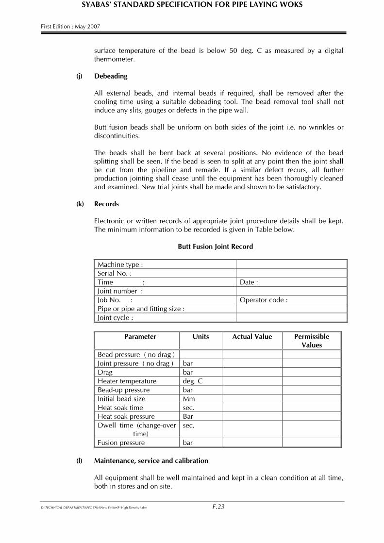
(j) Debeading All external beads, and internal beads if required, shall be removed after the
cooling time using a suitable debeading tool. The bead removal tool shall not induce any slits, gouges or defects in the pipe wall.
Butt fusion beads shall be uniform on both sides of the joint i.e. no wrinkles or
discontinuities. The beads shall be bent back at several positions. No evidence of the bead
splitting shall be seen. If the bead is seen to split at any point then the joint shall be cut from the pipeline and remade. If a similar defect recurs, all further production jointing shall cease until the equipment has been thoroughly cleaned and examined. New trial joints shall be made and shown to be satisfactory.
(k) Records Electronic or written records of appropriate joint procedure details shall be kept.
The minimum information to be recorded is given in Table below.
Butt Fusion Joint Record
Machine type : Serial No. : Time : Date : Joint number : Job No. : Operator code : Pipe or pipe and fitting size : Joint cycle :
Parameter Units Actual Value Permissible
Values Bead pressure ( no drag ) Joint pressure ( no drag ) bar Drag bar Heater temperature deg. C Bead-up pressure bar Initial bead size Mm Heat soak time sec. Heat soak pressure Bar Dwell time (change-over
time) sec.
Fusion pressure bar (l) Maintenance, service and calibration All equipment shall be well maintained and kept in a clean condition at all time,
both in stores and on site.
D:\TECHNICAL DEPARTMENT\SPEC YHH\New Folder\F- High Density1.doc F.23
SYABAS’ STANDARD SPECIFICATION FOR PIPE LAYING WOKS First Edition : May 2007 The equipment shall be serviced and calibrated regularly. The frequency at which
this is carried out will be different for individual items of equipment and will also depend on usage but should be at least once every 6 months.
15.3 Electro-fusion Socket Jointing 15.3.1 General With electro-fusion socket fusion, an electrical resistance element is incorporated in the
socket of the fitting which, when connected to appropriate power supply, melts and fuses the material of the pipe and fitting together.
The effectiveness of this technique depends on the attention to cleanliness, in particular the removal of the contaminated surface of the pipe over the socket depth.
Electro-fusion fittings are available in the range 20mm to 315mm although larger sizes
are now under development. There are 2 control systems specified – manual time selection and automatic time
selection. Both are described in this section. 15.3.2 Equipment The control box input supply shall be from a nominal 220 volt generator. NO EXTENSION LEADS SHALL BE USED ON THE CONTROL BOX OUTLET
CONNECTORS WARNING : Control boxes are not intrinsically safe and shall not therefore be taken
into the trench. Pipe surface preparation tool capable of removing the contaminated surface of the pipe
in excess of the insertion depth before welding is attempted. The tool shall remove a layer 0.2 – 0.4mm thick from the outer surface of the pipe preferably as a continuous strip of swarf over that length and round the pipe.
NOTE : Hand scrapers can be difficult to use effectively in trench conditions. Pipe clamps or other approved method for restraining, aligning and re-rounding the
pipes during the weld cycle shall be used. Pipe cutters including saw and saw guide. 15.3.3 Electro-fusion Jointing Method
(a) Preparation Check that the pipe ends to be jointed are cut square to the axis and any burrs
removed. Wipe pipe ends using clean, disposable, lint-free material to remove traces of dirt
or mud, etc.
D:\TECHNICAL DEPARTMENT\SPEC YHH\New Folder\F- High Density1.doc F.24
SYABAS’ STANDARD SPECIFICATION FOR PIPE LAYING WOKS First Edition : May 2007
Mark the area over which the contaminated surface is to be removed, i.e. in excess of the penetration depth, on each pipe to be jointed by placing the socket of the bagged fitting alongside the pipe and. Trace a line round the circumference at the appropriate distance from the pipe end using a suitable marker.
DO NOT REMOVE THE FITTING FROM ITS PACKING AT THIS STAGE Connect the electro-fusion control box input leads to the generator. Check that there is sufficient fuel for the generator to complete the joint. Check that reset stop button, if fitted on the control box, is in the correct mode. Using the pipe end preparation tool, remove the entire surface of the pipe
uniformly, preferably as a continuous swarf over the area identified, i.e. in excess of penetration depth.
(b) Electro-fusion Jointing Procedure Remove the fitting from its packaging and check that the bore of the fitting is
clean and dry. If necessary, dry it with clean, disposable, lint-free material and degrease with a clean cloth dampened by a suitable solvent like aceton liquid.
NOTE 1 : Isopropanol is a suitable cleaner for the material if permitted by the site
health and safety regulations. Insert the pipe ends into the fitting. NOTE 2 : It is recommended to mark pipe ends with an indelible pen to ensure
pipe depth of entry is maintained and a visible record retained when fusion is complete.
Using the pipe clamps, secure the pipes so that they cannot move during the
fusion cycle. Check that the pipe ends and the fitting are correctly aligned. If applicable, remove the terminal caps from the fitting. Start the generator and check that it is functioning correctly. Connect the control box output leads to the fitting terminal and check that they
have been fully inserted. Switch on the control box where applicable. Commence the fusion joining procedure in accordance with the control box
instruction and check indicated jointing time with time shown on fitting. Scan the bar code magnetic card which is provided together with the fusion
socket. Details of the fusion socket will be displayed on the welding set. Press the start button on the control box and check that the heating cycle is
proceeding as indicated by the display countdown.
D:\TECHNICAL DEPARTMENT\SPEC YHH\New Folder\F- High Density1.doc F.25
SYABAS’ STANDARD SPECIFICATION FOR PIPE LAYING WOKS First Edition : May 2007
On completion of the heating cycle, the melt indicators should have risen. If there is no apparent movement of the melt indicators, the joint should be cut out and a new joint made.
If a satisfactory joint has been made, the joint shall be left in the clamps for the
cooling time specified on the fitting. NOTE : If the fusion cycle terminates before completion of the countdown, check
for faults as indicated by the control box warning lights. Do not attempts a second fusion cycle if countdown of the first cycle reached more than half of the total time require and for at least one hour after the first attempt.
(c) Maintenance , Servicing and Calibration All equipment shall be well maintained and kept in a clean condition at all time,
both in stores and on site. The equipment shall be serviced and calibrated regularly. The frequency at which
this is carried out will be different for individual items of equipment and will also depend on usage, but should be at least once every 6 months. Guidance shall be sought from the equipment manufacturer and a scheme of calibration and servicing implemented. Particular attention shall be given to the control box and generator.
(d) Records Written records of appropriate fusion procedure details shall be kept as required
using the format approved by the S.O. 15.4 Electro-fusion Saddle Jointing 15.4.1 General With electro-fusion saddle jointing, an electrical resistance element is incorporate in the
base of the saddle which, when connected to an appropriate power supply, melts and fuses the material of the pipe and fitting together.
The effectiveness of this technique depends on attention to cleanliness, in particular the
removal of the contaminated surface of the pipe over an area equivalent to the saddle base.
Electro-fusion saddles are available to fit all commonly used main sizes with sizes 20,
25 or 32mm service connections. Outlet connections are also available up to nominal size 180mm.
Two methods of holding the tapping tee saddle during the fusion cycle are used, top
loading and under clamping systems. However, because of the variations of equipment used for each method, common procedures for holding the saddle during the fusion cycle cannot be specified. For each type of fitting used, the manufacturer’s procedure for holding the fitting during the fusion cycle should be followed.
D:\TECHNICAL DEPARTMENT\SPEC YHH\New Folder\F- High Density1.doc F.26
SYABAS’ STANDARD SPECIFICATION FOR PIPE LAYING WOKS First Edition : May 2007 15.4.2 Equipment The control box input supply shall be from a nominal 220 volts. NO EXTENSION LEADS SHALL BE USED ON THE CONTROL BOX OUTLET
CONNECTORS. WARNING : Control boxes are not intrinsically safe and shall not be taken into the
trench. Pipe surface preparation tool capable of removing the contaminated surface of the pipe
over the full area of the saddle base. The tool shall remove a surface layer 0.2 – 0.4mm thick.
Pipe-clamp with suitable dimension for making service or branch connections. 15.4.3 Electrofusion Saddle Jointing Method
(a) Preparation Expose the pipe onto which the tapping tee saddle is to be assembled. Clean the pipe over the general area on which the saddle is to be assembled using
clean, disposable, lint-free material and use clean water only. Without removing the fitting from its packaging, place it over the required
position on the main. Mark the pipe surface all round and clear of the saddle base area.
Remove the surface of the pipe to a depth of 0.2 to 0.4mm over the full area
marked using a suitable tool. Remove the swarf. Check that reset stop button on the control box, if fitted, is in the correct mode. (b) Electro-fusion Saddle Jointing Procedure Position the fitting base onto the prepared pipe surface and install the saddle
clamp to the saddle tee. Remove the terminal caps from the fitting. Check that there is sufficient fuel for the generator to complete the joint. Start the
generator and check that it is functioning correctly. Connect the electro-fusion control box input leads to the generator. Connect the control box output leads to the fitting terminals and check that they
have been fully inserted. Switch on the control box if applicable. Commence the fusion jointing procedure in accordance with the control box
instructions and check indicated joint time shown on fitting.
D:\TECHNICAL DEPARTMENT\SPEC YHH\New Folder\F- High Density1.doc F.27
SYABAS’ STANDARD SPECIFICATION FOR PIPE LAYING WOKS First Edition : May 2007
Press the start button on the control box and check that the heating cycle is proceeding as indicated by the display count-down.
On completion of the heating cycle, the melt indicator should have risen. If there is no apparent movement of the melt indicator, where incorporate, a new saddle joint should be made. Cut the tee of the faulty joint from its base.
If a satisfactory joint has been made, the joint shall be left in the clamps for the
cooling time specified on the fitting label. NOTE : If the fusion cycle terminates before completion of the count-down, check
for faults as indicated by the control box warning lights. DO NOT attempt a second fusion cycle.
NOTE : DO NOT attempt to tap the pipe with the integral cutter for at least 10
minutes after completion of the fusion cycle. (c) Maintenance, Servicing and Calibration All equipment shall be well maintained and kept in a clean condition at all time,
both in stores and on site. The equipment shall be serviced and calibrated regularly. The frequency at which
this is carried out will be different for individual items of equipments and will also depend on usage but should be at least once 6 months. Guidance shall be sought from the equipment manufacturer and a scheme of calibration and servicing implemented. Particular attention shall be given to the control box and generator.
(d) Records Written records of appropriate fusion procedure details shall be kept as required
using the format illustrated below.
ELECTROFUSION JOINT RECORD Control Box Serial No. : Units Operator Code : Time : Date : sec. Ambient Temperature : oC Joint Number : Type of Fitting : Target Fusion Time : sec Achieved Fusion Time : sec Joint Status : Power profile :
A well-made electrofusion saddle joint should have the following features:
The melt indicator should have operated where:
• There should be no melt flowing from round the saddle base; • There should be evidence of pipe surface preparation round the saddle base.
The following features indicate faults during the assembly / fusion operation:
D:\TECHNICAL DEPARTMENT\SPEC YHH\New Folder\F- High Density1.doc F.28
SYABAS’ STANDARD SPECIFICATION FOR PIPE LAYING WOKS First Edition : May 2007
(1) Fusion indicator fails to operate Causes : (a) incorrect fusion time selected – too short ;
(b) control box out of specification – under voltage; (c) fitting heating coil failure; (d) incorrect fitting for size of main; (e) top load too low on loading tool.
(2) Excess melt indicator or from saddle base Causes : (a) incorrect fusion time selected – too long;
(b) control box out of specification – over voltage; (c) insufficient pressure from top loading assembly tool; (d) time failure – too long; (e) incorrect fitting for size of main; (f) top load too high on loading tool.
(3) Inadequate fusion of saddle base on main Causes : (a) lack of pipe preparation;
(b) fitting heating coil failure. 15.5 Mechanical Joints
(a) General All mechanical fittings used shall be assembled in accordance with the
manufacturer’s instructions and all metal fittings should be suitably protected from corrosion as stipulated in clause “Metal Parts”.
(b) Transition joint from HDPE pipe to flanged metal fittings For transaction from HDPE pipe to flanged metal fittings, either HDPE stub flanges
with metal backing rings or mechanical flanged adaptors of approved types complied with MS 1058 or EN 12201 shall be used. The flanged joint gasket and bolt length used shall be appropriate to the particular adaptor.
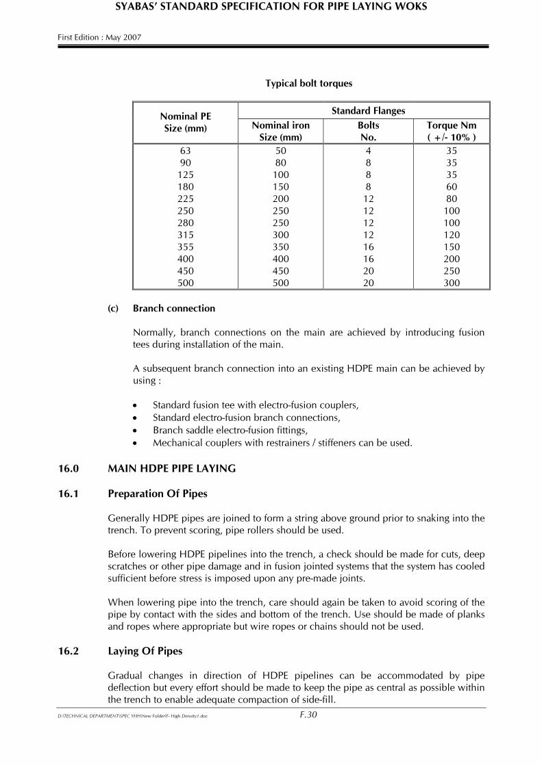
When tightening bolts and nuts for the flanges, care should be taken to produce an even torque load ( torque wrench ) to the limits as follows. The use of a torque wrench is strongly recommended. Typical bolt torques shall be as shown in Table below.
D:\TECHNICAL DEPARTMENT\SPEC YHH\New Folder\F- High Density1.doc F.29
SYABAS’ STANDARD SPECIFICATION FOR PIPE LAYING WOKS First Edition : May 2007
Typical bolt torques
Standard Flanges
Nominal PE Size (mm) Nominal iron
Size (mm) Bolts No.
Torque Nm ( +/- 10% )
63 90 125 180 225 250 280 315 355 400 450 500
50 80
100 150 200 250 250 300 350 400 450 500
4 8 8 8 12 12 12 12 16 16 20 20
35 35 35 60 80
100 100 120 150 200 250 300
(c) Branch connection Normally, branch connections on the main are achieved by introducing fusion
tees during installation of the main. A subsequent branch connection into an existing HDPE main can be achieved by
using : • Standard fusion tee with electro-fusion couplers, • Standard electro-fusion branch connections, • Branch saddle electro-fusion fittings, • Mechanical couplers with restrainers / stiffeners can be used.
16.0 MAIN HDPE PIPE LAYING 16.1 Preparation Of Pipes Generally HDPE pipes are joined to form a string above ground prior to snaking into the
trench. To prevent scoring, pipe rollers should be used. Before lowering HDPE pipelines into the trench, a check should be made for cuts, deep
scratches or other pipe damage and in fusion jointed systems that the system has cooled sufficient before stress is imposed upon any pre-made joints.
When lowering pipe into the trench, care should again be taken to avoid scoring of the
pipe by contact with the sides and bottom of the trench. Use should be made of planks and ropes where appropriate but wire ropes or chains should not be used.
16.2 Laying Of Pipes Gradual changes in direction of HDPE pipelines can be accommodated by pipe deflection but every effort should be made to keep the pipe as central as possible within the trench to enable adequate compaction of side-fill.
D:\TECHNICAL DEPARTMENT\SPEC YHH\New Folder\F- High Density1.doc F.30
SYABAS’ STANDARD SPECIFICATION FOR PIPE LAYING WOKS First Edition : May 2007
The bending of HDPE pipelines is permissible and the properties of fusion jointed systems enable changes of direction without recourse to the provision of special bends or anchor blocks. However, the pipe should not normally be cold bent to a radius less than 25 times the outside diameter of the pipe. For push-fit or mechanical non end-load resistant jointing systems, anchor blocks to withstand the resultant thrusts must be provided. Under no circumstances should hot bending be attempted on site. For installation of heavy flanged fittings, provision should be made for concrete support both for the weight and to resist the turning moments associated with valves and hydrants. HDPE pipes and fitting may be partially or completely surrounded by concrete but they should be protected by 3mm rubber membrane to avoid possible damage during pouring or compaction to prevent high localized stresses.
After completion of an installation, pipe work and fittings should be inspected and made ready for testing to ensure the safety and efficiency of the systems. The trench may be backfilled prior to testing; but it is advisable to leave at least the joints exposed throughout the test. Complete and accurate records should be taken of the installation. It is useful for records to be taken before the pipes are buried. To assist the future location of the pipelines, a marker tape shall be laid along the line of the main and connect at each end to either a sluice valve or hydrant. The recommended position of the tape is 350mm below the surface directly above the crown of the pipe.
17.0 INSTALLATION OF SERVICE PIPES 17.1 General
This section gives details of installation of HDPE service pipes. A service pipe is that part of the water supply system which conveys water from the distribution main to the consumer’s premises and is subjected to water pressure from that main. It is considered to comprise two sections: • The COMMUNICATION PIPE is that part of the service pipes from the main up to
the and including the consumer’s meter situated at the boundary of the consumer’s property. The water supply authority is responsible for the installation and maintenance of the communication pipe.
• The SUPPLY PIPE is that part of the service pipe from the consumer’s meter into
the premises up to the storage cistern. The customer is responsible for the installation and maintenance of the supply pipe.
17.2 Laying of Communication Pipe
Wherever practicable the whole communication pipe should be laid in a straight line at right angles to the main when viewed on plan. This assists future location and identification of these pipes.
D:\TECHNICAL DEPARTMENT\SPEC YHH\New Folder\F- High Density1.doc F.31
SYABAS’ STANDARD SPECIFICATION FOR PIPE LAYING WOKS First Edition : May 2007
Slight snaking of the communication pipe in the vertical plane is permitted without overstressing the connection to the main. However, care must be taken not to kink the pipe and/or impart excess bending moment to the saddle tapping. The preferred method would seem to be the simple straight connection at right angles to the main with changes in direction or level achieved by installation electrofusion elbows to avoid overstressing of the communication pipe. Where road and / or drain crossing is required, suitable GI ducting should be provided to accommodate the communication pipe.
18.0 CONNECTION TO HDPE PIPE 18.1 Connection to HDPE Pipe
Connections to HDPE pipe shall vary according to size. Large branch connections are usually effected by standard tees, while medium sizes are effected by branch saddles. Other communication pipe connections (< 63mm) are usually affected by electrofusion saddles. Electro-fusion saddles have a self-tapping ferrule system whereby the cutter forms an integral part of the ferrule connection and after withdrawal remains within the ferrule head. Self-tapping ferrules may be electro-fusion jointed on to “live” mains.
18.2 Connection to Pipes of Other Materials
HDPE communication pipes may be connected to pipes of other materials such as AC, UPVC, MS etc. The use of standard under pressure tapping machine are necessary for connection to “live” mains.
Saddle straps are usually required for tapping to AC and uPVC pipes, while traps may
also be required for MS pipes. 19.0 JOINTING OF SERVICE PIPES 19.1 Jointing of HDPE Service Pipes Butt fusion is not normally considered appropriate for the smaller sizes of pipes i.e.
<63mm. The usual method of jointing service pipes is by using electro-fusion couplers
19.2 Jointing of Dissimilar Service Pipes
Where dissimilar service pipe material are to be joined (e.g. when replacing a section of metallic pipe with HDPE), special joint adapters are necessary. Two (2) types of adapters commonly used are: • Transition electro-fusion couplers
Care should be taken to ensure that all pipe jointing is adopted in accordance with the manufacturer’s recommendations.
D:\TECHNICAL DEPARTMENT\SPEC YHH\New Folder\F- High Density1.doc F.32
SYABAS’ STANDARD SPECIFICATION FOR PIPE LAYING WOKS First Edition : May 2007 19.3 Testing and Commissioning of Service Pipes
These requirements will be in accordance with the standard procedure laid down by the water authorities. These standards will normally require, as a minimum, the adequate flushing of the service pipes and the testing of all pipes and joints to the maximum head to which the system is to be subjected.
20.0 REPAIR METHODS
Whilst repairs to burst mains and services are usually carried out in difficult and dirty conditions, every effort should be made to keep all pipe and joint surfaces clean and the working area as dry and uncontaminated as possible through the operation. The completed repair should be examined and approved under working conditions before re-bedding, side filling and backfilling take placed. Special attention should be given to the replacement and compaction of suitable material under and around the repair.
20.1 Repairs to HDPE Pipe 20.1.1 General
The extent of the pipe defect or fracture should be determined to ensure that the
remainder of the pipe has not been weakened or damaged in any way. The inspection should also ascertain the extent to which the bed and surround may have been disturbed in the vicinity.
When repairing a burst it is recommended that a short length of pipe ( say 1 meter ) on
each side of the damaged, since the defect may extend on the inner surface of the pipe. 20.1.2 Emergency Repairs The emergency temporary repair of a HDPE pipe may be carried out by using a split
collar in the normal way but a more permanent repair should be undertaken as soon as possible.
20.1.3 Permanent Repairs Using Fusion Joints Butt fusion jointing is not usually a practical approach in repairing a burst pipe in
trench. However, electro-fusion couplers are more commonly used for repair of HDPE pipes.
The repair of a HDPE pipe requires the defective length to be carefully cut out and
replaced by a measured length of HDPE pipe. It is important that the replacement pipe is of the same pressure class.
The electro-fusion couplers, after removing the central stopper, may be slipped over the
existing pipe ends and fusion joints made. Care must be taken to ensure all ends are cut square and dry and clean prior to jointing. Marking of the pipe will ensure that the coupler is placed centrally over the joint.
Small leaks on HDPE pipe may be repaired by attaching an undrilled electrofusion
saddle over the hole of the pipe. D:\TECHNICAL DEPARTMENT\SPEC YHH\New Folder\F- High Density1.doc F.33
SYABAS’ STANDARD SPECIFICATION FOR PIPE LAYING WOKS First Edition : May 2007 20.1.4 Permanent Repairs Using Mechanical Joints
Another alternative means of jointing the replacement pipe is by means of a special mechanical type repair clamps in accordance with the manufacturer’s recommendations.
Mechanical fittings are encouraged for site repair.
20.1.5 Repairs to HDPE Service Pipe
The repair of a HDPE service pipe requires the defective length to be carefully cut out and replaced by a measured length of pipe of the same pressure class using electro-fusion or mechanical end-load resistance couplers.
Small breaks may be repaired using electro-fusion saddle.
There is a wide range of mechanical repair couplers for service pipes. In all cases the manufacturer’s recommendations should be followed.
20.1.6 Squeeze-Off Closure Technique
Isolating HDPE pipelines by forcibly pinching or squeezing the walls together is an effective method used in many repair situations where it may be inconvenient and / or expensive to close down and empty pipelines. The squeeze-off technique involves applying pressure to the outside walls of the pipe across a diameter using two tangential bars. The bars are forced together, collapsing the pipe until a seal is formed by the upper and lower walls meeting. Squeeze clamps are available for pipe up to 180mm. The following recommendations are given for the use of the squeeze-off technique: • Only specially designed equipment should be used with correct stops to avoid over
compression of the pipe.
• Do not use within 5 pipe diameters of a fitting, fusion joint or a previous squeeze-off operation.
On release of the squeeze the pipe should be: • Inspected and re-rounded if necessary • Renewed if there is any indication of damage • Adequately marked and recorded.
D:\TECHNICAL DEPARTMENT\SPEC YHH\New Folder\F- High Density1.doc F.34