section section c - chassis - the tvr site · cerbera servicei"workshop lvlanual b front of...
TRANSCRIPT
� ) .
RR ---- -- - -- -- - - -- -- -- - - -- - - -
'\1
Section Section C - Chassis N.B. Chassis part numbers begin with (A)
Hosted and optimised by www.TheTVRSite.com

LJi ,\41 --------
. . == =- -=.
contents
...................................... -11 ..................................... . Remove and Replace Body
Hosted and optimised by www.TheTVRSite.com

CERBERA SERVICEI"WORKSHOP lVlANUAL
B
Front of chassis
C
E
Rear of chassis
A
Hosted and optimised by www.TheTVRSite.com

fiR ---- -- - --- - - -- - - -- - - -- - -
Service I Workshop Manual
Body from Chassis - Removal/Replacement Procedure
Hosted and optimised by www.TheTVRSite.com

&ill --------.
Service/Workshop Manual -Removal of Body
Service/Workshop Manual-Removal of Body
Service/Workshop Manual -Removal of Body
Service/\lVorkshop Manual -Removal of Body
Removal/Replacement of Body from Chassis
Before commencing the operation of replacing a chassis, the main dash, n/ s unc:ier dash panel, seats, se.at belts, and all carpets must be lifted/ removed to enable access to the fixing bolts in the floor. Once this has been done remove the 8 bolts located in the floor pan, 4 of which are located
.•.. __ . .. ______ ..... _. ___ . _ _ --'-li _"-'-ll..U'-'-"-'J..LJ..._y_"' ... J..L •. \--'.-' .. j-_\.LL • .J..u;:..J.J..lJ..l..:J .. L� «tion at front
2
3
4
of section.
Next the bolts that hold ·the roll cage to the chassis need to be removed.(B) of the illustration at front of section. When replacing the bolts care should be takert not to over tighten the bolts & strip the threads.
Next the bolts that hold the roll cage to the chassis need to be removed;(B) of the illustration at front of section. VVhenreplacing the bolts care should be taken not to over tighten the bolts & strip the threads. Torque to a value of?
At this stage the steering must be disconnected and the engine, radiator, Aeon equipment, fuel pump wiring, earth leads - chassis/battery, engine loom, starter lead, reverse light switch, speed sensor wiring must be removed. Guidance for these operations will appear further on in this manual in their relevant sections. ·Once completed move round to the front of the car and remove the bolts that are located in position (C) of the illustration at front of section.
Hosted and optimised by www.TheTVRSite.com

CERBERA SERVICEIW"ORKSHOP .MANUAL
3
Service!Workshop Manual-Removal of Body
4
Service!Workshop Manual -Removal of Body
5
At this stage the boot triml fuel tank and ECU/s must be removed.Then the bolts at the rear cart be removed.(D) of the illustration at front of section.
Once all the bolts have been removed the body wilt lift completely off the chassis.
It is recommended that at least eight men are needed to complete this operation - two at each corner as shown.
Once the body has been lifted, the chassisl should be pulled out and the body placed gently on the ground. ( Some kind of protection is recommended if the orginal body is to be reused to prevent damage to the body orpaint work.)
6 To replace the new body reverse the outlined
......... -...... ::.lIIL.-.-.--... ----.... --.. -.-cc--�-- operation ensuring to torque all bolts to their Servic�!Workshop Manual -Removal of Body given settings.
Hosted and optimised by www.TheTVRSite.com

contents
····················· .. · .. · .. · .. ······11· .. ····· .... ····· ...... ·· ............ .
Bonnet
··· .. ············ .. · .. ······ .... ······IlJ···················· ................. .
Boot
·· .. · .. ······ .. ······· .. ······· .. ·····CiI ···· .. · .... ··· .. · .... ····· ........... .
Doors
...................................... I!J ..................................... .
Top Engine Cover
.. · .. ·· .. ··· .. ····· .... ······ .... ·····11· .. · .. ·· .. ···· ...... ······ .. ·· ....... .
Engine Bay cover
Hosted and optimised by www.TheTVRSite.com

fiR ---- -- - --- - - -- - - -- - - -- - - -
Service / Workshop Manual
Body Panels - Removal/Replacement Procedure
Hosted and optimised by www.TheTVRSite.com

ftH ------ --- ---
Service/Workshop Manual - Boot Removal
Service/Workshop Manual - Boot Removal
2
Boot - Removal/Replacement Procedure
To remove the boot simply unbolt the 4 x MS
bolts with spring and flat washers.
This will release the boot and it can be removed.
To ensure the new boot panel is in the correct position loosely fasten the securing bolts, dose the boot and line up the shut lines with the shut lines of the body of the car. Once this has been done the 4 x MS bolts can be tightened to hold the boot in place. If further adjustment is
3 required the two bolts on each hinge can be
_k_ ... _ ..... _ ... _. __ ...... _ ... _ ... __ . . _ .. _ loosened and the hinge can be repositioned.
Service/Workshop Manual - Boot Removal
Hosted and optimised by www.TheTVRSite.com

CERBERA SERVlCEIlN"ORKSHOP l\ILANUAL
Service!Workshop Manual - Door Removal
Service!Workshop Manual - Door Removal
Doors - RemovallReplacement Procedure
When removing the doors on a Cerbera the first operation is to disconnect the battery (see service section) and all the electronics that are routed through the door for the electric windows and door opening mechanism. The wiring connections are located on the outside of each footwell under the carpet. There should
.. be thre� cormector blocks as "'.I .... n'CATn
Once this has been done the bolts, 2 x M8, on the lower door bracket can be removed.
Finally theMIO nut on the top bracket can be removed. When removing the top securing boIt the door will come free so it is important that somebody is holding the door. N.B. Inside the bracket there is a bush that may fall out whilst completing the operation.
Hosted and optimised by www.TheTVRSite.com

�. - --- - -
Service/Workshop Manual - Scoop panel
Service/Workshop Manual - Scoop panel
ServIce/Workshop Manual - Scoop panel
2
3
Scoop panel - Removal/Replacement Procedure
To gain access to the scoop panel, firstly raise the bonnet.
Disconnect the washer pipes.
Then remove th€ 2 x M8 allen bolts that secure the panel at each side as shown. To replace the panel, reverse outlined procedur�.
Hosted and optimised by www.TheTVRSite.com

CERBERA SERVICEI"WORI'(SHOP MANUAL
Service!Workshop Manual - Bonnet Removal
2
Service!Workshop Manual - Bonnet Removal
3
4
Service/Workshop Manual - Bonnet Removal
Bonnet - Removal/Replacement Procedure
The bonnet is secured to the car at the front, at its hinges. To gain acc:ess to the hinge brackets on the front of the bonnet, the bonnet will have to be raised and secured on the bonnet stay clip.
Loosen the 2 x M8 locking nuts that secure the bonnet to the bracket. Then loosen the bracket securing nuts from inside the body.
Repeat this operation on the opposite side of the bonnet and this should give enough room for the bonnet to come free from the bonnet bracket.
The bonnet can then be removed. To replace a bonnet reverse the outlined procedure.
Hosted and optimised by www.TheTVRSite.com
Service/Workshop Manual - F-1 panel
2
Seroice/Workshop Manual- F-1 panel
3
Service/Workshop Manual- F-1 panel
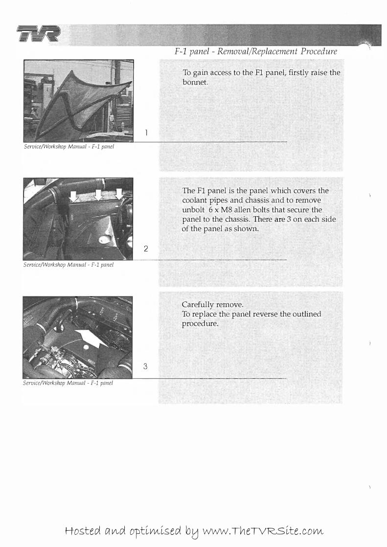
F-l panel - Removal/Replacement Procedure
To gain access to the FI panel, firstly raise the bonnet.
The FI panel is the panel which covers the coolant pipes and chas.sis and to remove unbolt 6 x M8 allen bolts that secure the panel to the chassis. There are 3 on each side of the panel as showil"�
Carefully remove. To replace the panel reverse the outlined procedure.
Hosted and optimised by www.TheTVRSite.com