section two-linkage adjustments a. manual linkc9e · pdf filesection two-linkage adjustments...
TRANSCRIPT

SECTION TWO-LINKAGE ADJUSTMENTS
A. Manual LInkc9e Adjustments
0 This applies to all Fords, Mercurys, and Lincoins except the 1957Mercury
1. WIth the engine off disconnect theupper end of the manual shift rodfrom the steering column.
7$

2. Set the selector lever in drive position.
Chapter IIISection TWO
3. Place the manual lever on the transmission in the drive detent,or the secondposition from the bottom.
4. Rotate the manal shift rod clevis to obtain the shortest length that will Permitthe clevis pin to enterthe grommet in the selector lever.
5. Lengthen the rod by turning the clevis two additional turns counterclockwise.
6. Install the clevis pin, and lock the clevis in place with its locknut.
7. Checkthe pointer alignment for all positions of the selector lever.
8. last, check the adjustmentof the starter neutral switch located on the steeringcolumn, as follows in B
B. Startd Ne44,1J4s . ASnmeiw
This switch has an adjustmentof 7 degreesin either direction from the
1. Loosen the screws which attachtheswitch to the steeringcolumn.
C On 1957 Mercurys theneutral switch is locatedunder the dashboard.
2. Then, position the switch so that the starter circuit is closedwhen the selectoris in neutral position
3. Checkthe starter circuit with the selector in every position
C The starter circuit must be open in all positions exceptneutral.
central neutral position.
4. With the neutral switch properly positioned, tighten the attachingscrews.

Chapter III
C. Manual Selector Cable Adjustnient 1957 Mercury Only
Section TWO
1. Raise the car, remove the splash shield, and remove the pipe plug from lcftside of transmissioncase
2. Removethe 1nrk releasecontrol cable from lever and clamp.
C The nrk release cable must not be connectedtn the adjusting bracket or park release lever while making the manual selector cableadjustment.
3. Loosen the control cable mounting bracket retaining Screw and washer leavingit finger tight.
4. Hold ‘D’’ button on transmissionkeyboard selector in the FULLY DEPRESSED
5. Move adjusting bracket downward to limit of travel
6. Install the gagilig tool in place ofpipe plug in the transmissioncaseas showix.
7, Pull upward on the selector cableand housing assembly until the pinin the gage seatsin the locating slotof the selector cable connectorsleeve.
8. Leaving the tool in place, torque thepounds.
control cable mounting screw 18-22 foot-
9. Removethe tool, and replacethe pipe plug in transmissioncase.
10. Check for correct keyboard control operation of the keyboard buttonsbeforeproceeding with the park cable adjustment.
D. Park Cable Adjustment 19S7 Mercury Only
A correct park release cable adjustment cannot be obtaineduntil proper selectorcable adjustmentis completed.
1. Install the ‘rk cable on the pin of the park releaselever and install the clampand screw on the adjusting bracket.
position.
so

2. Fully depressthe park bar on keyboardselector
Chapter IiiSection Two
3. Install the gage over the torsionlever support pin in transmissioncaseand the pin on the park releaselever
4. Remove cable slack by pulling cable housing toward rear of car.
5. Holding cable in this position, tighten the cable clanip screw.
6. Removethe gage.
7. Install the washerand retaining pin in the 1nrk releaselever pin.
8. Check operationof keyboardbuttonsand park bar.
C If the park pawl does not fully engagewhen the park bar is pushedinto the ON position, it may be necessaryto move the park releasecable housing an additional 1/8 inch toward the roar of the car. Thiscondition may exist on a few cars with the earlier 1957 productiontransmissions, numbers PBA-7000-G and PAN-7000-L.
E. Throttle Linkage Adjustments
There are so many variations in throttle linkage hook-ups that it is impossible toprovide specific proceduresfor all the cars using the transmissioncovered in thisbook. However,similarities do exist in the basic procedureswhich follow.
Though linkage hook-ups, and therefore procedures vary, the objective of throttlelinkage adjustmentdoes not. That objective is to adjust the linkage so that therewill be a proper relationship between carburetorthrottle openingsand the movement of the transmission throttle lever. If the linkage is correctly adjusted--thecarburetor and transmission will combine to provide smooth shifting at proper
ARK RELEASE CA5LF
speeds. If it is not, slippage, bunched shifts, and rough shifting occur.
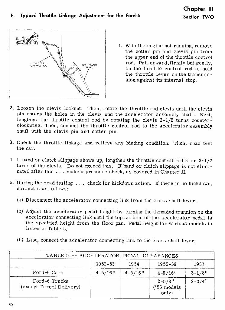
F. Typical Throttle Linkage Acilustment for the Ford-6Chapter IIISection TWO
1. With the engine not running, removethe cotter pin and clevis pin fromthe upper end of the throttle controlrod. Pull upward,firmly but gently,on the throttle control rod to holdthe throttle lever on the transmis -
sion againstits internal stop.
2. Loosen the clevis locknut. Then, rotate the throttle rod clevis until the clevispin enters the holes in the clevis and the accelerator assembly shaft. Next,lengthen the throttle control rod by rotating the clevis 2-1/2 turns counterclockwise0 Then, connect the throttle control rod to the acceleratorassemblyshaft with the clevis pin and cotter pin.
3. Check the throttle linkage and relieve any binding condition. Then, road testthe car.
4. 11 band or clutch slippageshows up, lengthenthe throttle control rod 3 or 3-1/2turns of the clevis. Do not exceedthis. If band or clutch slippage is not eliminatedafter this . . . makea pressurecheck,as coveredin ChapterII.
5. During the road testing . . . checkfor kickdown action. If there is no kickdown,correct it as follows:
a Disconnectthe acceleratorconnectinglink from the cross shaft lever.
b Adjust the accelerator pedal height by turning the threadedtrunnion on theacceleratorconnectinglink until the top surface of the accelerator pedal isthe specified height from the floor pan. Pedalheight for various models islisted in Table 5.
b Last, connectthe acceleratorconnectinglink to the cross shaft lever.
TABLE 5 -- ACCELERATOR PEDAL CLEARANCES
Ford-6 Cars -
1952-53 1954 1955-56 1957
4-5/16" 4-5/16" 4-9/16" 3-1/8"
Ford-6 Trucksexcept ParcelDelivery
2-5/8"‘56 models
only
2-3/4"
THROTTLECONTROL ROD ACCELERATOR
PEDAL
82

Chapter IIISection TWO
On Ford-6 trucks, the accelerator pedal should just
touch the detent stem when the car -
buretor hits its wide open stop. OnParcel Delivery trucks, this is theonly pedalheight specification. Throttie linkage for various Ford-6 carsand trucks are shown below.
1. Throttle linkage for 1957 Ford6-cylinder cars.
2. Throttle linkage for 1955 Ford-6trucks.
3. Throttle linkage for 1956 6-cylindertrucks except ParcelDelivery.
THROTTLE CONTROL
ACCELERATORPEDAL
THROTTLE CONTROL
THROTTLE CONTROL
83

Chapter IIISection TWO
4. Throttle linkage for 1956 parcelDelivery trucks.
G. Typical Throttle Linkage Adjustment for the Pord V-S1955-56 cars with 2-barrel carbueters
k the throttle control rodfrom the acceleratorassembly.
2. Then insert a locking pin throughthe bracketpoint ‘‘A’’.
a n d linkage holes
3. Adjust the lengthagainst its stop.
of the carburetor connecting link to close
4. Then adjustpedal height
the length of the accelerator assembly connectinglink to obtain aof 3-11/16 inches. Sec Table 6.
Dctt ASEMILY
ACCELAATORCOtNma ma
AcCEEEtArQE rECAI
O]ftE CONTROL RC
O!O :<!!
1. Disconnect
the carburetor
84

Chapter III
Section TWO
TABLE 6-- ACCELERATOR PEDAL CLEARANCES
1954 1955 1956 1957
Ford V-bwith 2-barrel carb. 3-3/16’’ 3_Il/Is 3 11/16’ 3-1/8’’with 4-barrel carb. 3-9/16" 3-9/16’’ 3-1/8"
Thunderbird 4-1/4’’ 4-1/4’ 47/B’’
Ford-S trucksexcept ParcelDelivery --
_______
2 5/8’’ 2 _3/411
5. Check the alignment at this point by sliding the gauge pin in and out of thebracket and linkage holes. It should move freely without any binding. Then,remove the pin.
6. Now, pull the upper end of the throttle control rod upward, firmly but gently,to hold the transmissionthrottle lever against its internal stop.
7. Then, rotate the clevis until it freely fits the pin on the acceleratorassemblylever.
8. Next, lengthen the throttle control rod by turning the clevis 2-1/2 turnscounterclockwise.
9. Then, connectthe throttle control rod to the accelerator assembly lever, holding the clevis in alignment to preventbinding, and tighten the locknut.
ID. Check the throttle linkage, and relieve any binding. Then road test the car.
11. If band or clutch slippage is evident, increase the length of the throttle rod3 or 3-1/2 turns. If slippage is not eliminated, it will be necessary to make apressure check, coveredin Chapter II.
12. Next, check the alignment of the accelerator assembly lever connecting link. The link must be parallelto the centerline of the engine. Ifthe connecting link is misaligned,loosenthe adjustmentscrew locknut.Then, turn the adjustment screwuntil correct alignment Is obtained,and tighten the locknut.
For various Ford V-S models, different gages are required to locateand hold proper linkage positions. The applications are shown in the
appendix. The gages serve the same purposeas the pin. Various linkages areshown below for various models. Procedures for all are similar
as

1955 Thunderbird throttle linkage.
On 1955 8-cylinder trucks,accelerator pedal height is
adjusted so that the pedal just touchesthe detent stern when the carburetorlever hits its wide open stop.
Chapter IIISection TWO
1955 Police Interceptor and Special8-cylinder engine throttle linkage.
1955 8-cylinder truck throttle linkage.
1956 Thunderbird throttle linkage. Throttle linkage for 1956 V-8 Fordswith 4-barrel carburetors.
ARATOR ASSEMBLY CONNECTING LINK
PEDAL
CARBURETORCONNECTING
LINKPOINT !A!
THROTTLE CONTROL POD
PEDAL
FLOOR PAN
DETENT ASSEMBLY
0
ACCELERATOR CONNECTING LINK
POINT A
NCARBURETOR CONNECTING LINK
THROTTLE CONTROL ROD
86

Chapter IIISection TWO
Throttle linkage for 1956 Ford 8-cylinder trucks.
‘ETORCEc’O
-
U E T C ON N EOG U
ONl
ACCELURMOTUNNCTNG *.. S - -.
cCE IT
THROTTLE CONTROC
Throttle linkage for 195’? v-B Fordcar with 4-barrel carburetor.
Throttle linkage ror 1957 Ford 8-cylinder Parcel Delivery truck.
On this model, the only accelerator pedal height
specification is to adjust the pedal sothat it just touches the detent stemwhenthecarburetor lever hits its wideopen stop.
Adjustments !dr Mercury and Lincoln
basically to all Mercurys from
I. Disconnect the rear end of the car-buretor link.
On 1954, ‘55,MercUI
and ‘56disconnect the
link at the carburetor.
2. Disconnect the clevis on the upper
end of the throttle control rod.
CCTLEROETEDAL
00! CGTCE
£CTOCON?< ECT!TCU
H. Typico Throttle Lijikage
1954 on.The procedures covered here apply
.7
Chapter IIISedion IWO
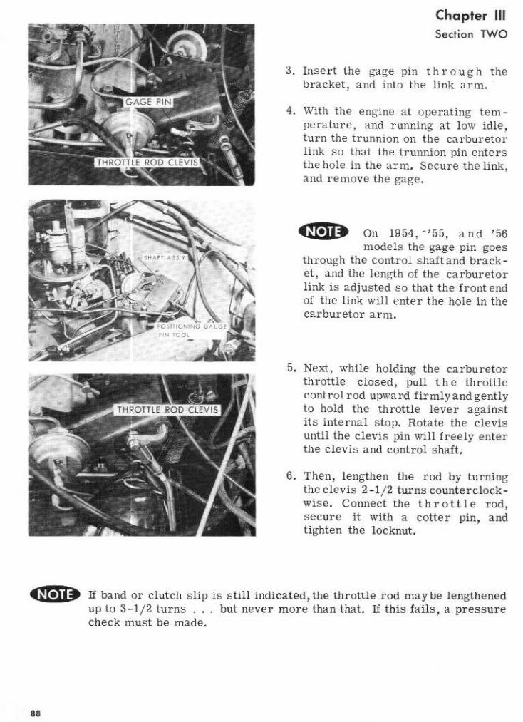
3. Insert the gage pin through thebracket, and into the link arm.
4. With the engine at operating tern -
perature, and running at low idle,turn the trunriion on the carburetorlink so that the trunnion pin entersthe hole in the arm. Sccure the link,and removethe gage.
0 On 1954, ‘Sfi, and ‘56models the gage pin goes
through the control shaftandbracket, and the lcngth of the carburetorlink is adjustedso that the front endof the link will enter the hole in thecarburetor arm.
5. Next, while holding the carburetorthrottic closed, pull the throttlecontrol rod upward firmly andgentlyto hold the throttle lever againstits internal stop. Rotate the clevisuntil the clevis pin will freely enterthe dcv is and control shaft,
6. Then, lengthen the rod by turningthc clevis 2-1/2 turnscounterclock-
wise, Connect the throttle rod,secure it with a cotter pin, andtighten the locknut.
If band or clutch slip is still indicated,the throttle rod maybe lengthenedup to 3-1/2 turns . . but never more than that. If this fails, a pressurecheckmust be made.
88

Chapter III
Secton TWO
The procedures for adjusting Lincoln throttle
linkage are the same as for Mercury. The forced lcickdown downshift, however, is adjustable. Withthe ignition off, and acceleratorpedal depressed,adjust the lengthof the toggle rod assembly so thatthe nylon bushinghas a clearanceof.10-inch from the top of the slot inthe accelerator shaft assembly.
On 1951, ‘52, and ‘53 Mercurys, the basic methodsof adjustmentapply.However, different linkage locating gages are uscd to position thelinkage properly. See the tool application chart in the appendix.
I. ThtoltIe LidcagtAj.stment -Mode with Tadioniet., and Pressure Gag.
This method of adjusting throttle linkage employs engine speed and transmissionhydraulic pressure readings as guides to the extent of adjustment. Its princiinlvalues in comlrison with other methods, are that it is easier to ‘tailor’ thelinkage and that mstrument readings provide a more preciseway of checking outcertain conditions. This method is generally used when conventional linkageadjustment does not provide a satisfactory job.
1, mstau a tachometer.
iUTlON Be sure engine idle and the anti-stall dashpot are adjusted tospecifications.
2. lnstaU the pressuregage.3. Adjust the manualand throttle link
age as described, and temporarilyconnect the throttle control rod tothe control shaft.
4. At this time, observethe fluid pressure at engine idle speed. If thepressure is above or below specificationssee Table 4, cage 59 makethe following corrections:a Dram and remove the bottomoil
pan.b If idle pressureIs above speci
fications,bend the throttle leverinternal stop counterclockwiseawayfroin the valve body - usingthe bending tool shown.
89

Chapter IIISection TWO
c If idle pressure is below specifications, or is erratic, trouble is indicatedwithin the transmission,and normal diagnosis proceduresshould be followedto locate the trouble.
d Install bottom oil pan with new gasket, and bring fluid level to full mark.
5. Set the brakes securely,and increasethe engine speed to 1,000 RPM in drive,using the acceleratorpedal. Note the readingon the pressuregage. If the pressure is below specifications see Table 4, page 59, lengthenthe throttle controlrod by turning the clevis counterclockwise 1/2 turn at a time, until the properpressureis reached. If the pressureis high, shortefl the throttle control rod byturning the clevis clockwise 1/2 turn at a time until proper pressureis reached.
ctAUTION These checks must be made quickly, the selector returned toI neutral position, and the throttle closed after eachcheckto avoid
overheatingthe transmission.
6. Reinstall clevis pin and cotter key, and tighten clevis locknut on the throttlecontrol rod.