sector 13 canted undulator upgrade hutch modification requirements
Post on 21-Dec-2015
222 views
TRANSCRIPT

Sector 13 Canted Undulator Upgrade Hutch Modification
Requirements

New pneumatic door shown 41.1” Wide. This could be as narrower as allowed since it will only be used for people access. Note this is white beam door.
New Wall. This is classified as white hutch front wall.
Double manual white beam doors 1.3m min width. Located as close as possible to outboard wall.
Shielded Beam Pipe
Approximate center line of 13-ID-C1 line
Wall penetration modification needed to accommodate the two guillotines, one for the shielded beam pipe the other for the 13-ID-C1 mono beam pipe
Wall penetration and guillotine needed to accommodate the shielded beam pipe to 13-ID-C2
PSS box mounts here off of a false wall that allows sliding doors to pass behind
Shorten existing crane for operation in C2.
Add new crane for operation in C1.

NotesAt least four more labyrinths should be budgeted.
Utilities:
Electrical:
Use existing box’s and split power between C1 and C2. Pass power in and out of existing or new labyrinths.
Lights may need to be moved / added. New light switches (inside and outside of hutch) are needed.
PSS:
A complete set of components (search buttons etc.) will be required for C1.
Water:
Keep only in C2.
Compressed Air:
Keep only in C2.
Crane:
Shorten existing crane in C2.
Add new crane.
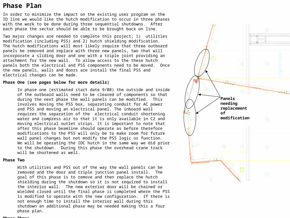
Phase PlanIn order to minimize the impact on the existing user program on the ID line we would like the hutch modification to occur in three phases with the work to be done during three sequential shutdowns. After each phase the sector should be able to be brought back on line.
Two major changes are needed to complete this project; 1) utilities modification (including PSS) and 2) hutch shielding modification. The hutch modifications will most likely require that three outboard panels be removed and replace with three new panels, two that will incorporate a sliding door and one with a triple joint providing an attachment for the new wall. To allow access to the these hutch panels both the electrical and PSS components need to be moved. Once the new panels, walls and doors are install the final PSS and electrical changes can be made.
Phase One (see pages below for more details)
In phase one (estimated start date 9/08) the outside and inside of the outboard walls need to be cleared of components so that during the next phase the wall panels can be modified. This involves moving the PSS box, separating conduit for AC power and PSS and moving an electrical panel. The inboard wall requires the separation of the electrical conduit shortening water and compress air to that it is only available in C2 and moving electrical outlet strips. It is important to note that after this phase beamline should operate as before therefore modifications to the PSS will only be to make room for future wall panel changes but not modify the PSS logic or function. We will be operating the IDC hutch in the same way we did prior to the shutdown. During this phase the overhead crane track will be shortened as well.
Phase Two
With utilities and PSS out of the way the wall panels can be removed and the door and triple junction panel install. The goal of this phase is to remove and then replace the hutch shielding during the shutdown so it is not required to install the interior wall. The new exterior door will be chained or wielded closed until the final phase is completed where the PSS is modified to operate with the new configuration. If there is not enough time to install the interior wall during this shutdown an additional phase may be needed making this a four phase plan.
Phase Three
With the new walls and doors installed during phase two the remaining work to be performed involves the PSS utilities, shielded beam pipe and guillotines. During this phase the new PSS configuration will be installed and tested and the final utilities installed. The SOE IDB will have both the white beam shutter and monochromatic beam shutter in place. The shielded beam pipe will be bridging IDB and IDC2 and the downstream wall of IDB and the new wall between C1 and C2 with be seal around the beam pipes with guillotines. At the end of this shutdown the old IDC hutch will be effectively operating as two independent hutches C1 and C2 completing the project.
Panels needing replacement of modification
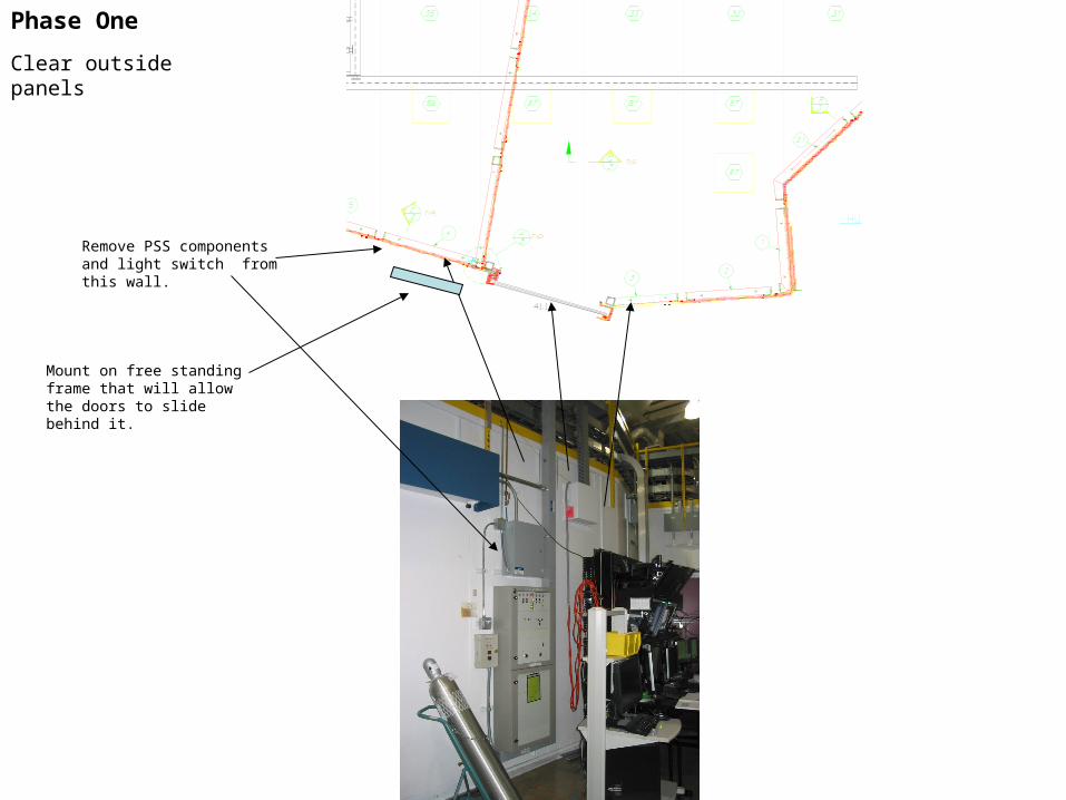
Remove PSS components and light switch from this wall.
Mount on free standing frame that will allow the doors to slide behind it.
Phase One
Clear outside panels
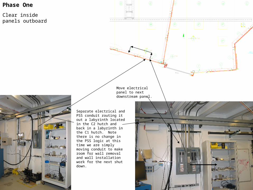
Phase One
Move electrical panel to next downstream panel.
Separate electrical and PSS conduit routing it out a labyrinth located in the C2 hutch and back in a labyrinth in the C1 hutch. Note there is no change in the PSS logic at this time we are simply moving conduit to make room for wall removal and wall installation work for the next shut down.
Clear inside panels outboard

Phase One
Clear inside panels inboard
Separate electrical conduit routing it out a labyrinth located in the C2 hutch and back in a labyrinth in the C1 hutch.
Move to next downstream panel.
Shorten water and compress air to that it is only available in C2