secure iot gateway reference design for bluetooth® low ... · important notice for ti reference...
TRANSCRIPT

Copyright © 2016, Texas Instruments Incorporated
Exosite
TM4C129 CryptoConnected/DXQFK3DG�
EthernetSub-1GHzCC1310
CC3120 Access point NFC
TRF7970ACC2650
NFCRF430
CC3100 Station TM4C123
/DXQFK3DG�
Wi-Fi Node
Gateway
TM4C123/DXQFK3DG�
Sub-1GHzCC1310
NFCRF430
TM4C123/DXQFK3DG�
Sub-1GHzCC1310
TM4C123/DXQFK3DG�
CC2650
NFCRF430
Sub-1GHz Nodes
BLE Nodes
1TIDUBY2A–August 2016–Revised September 2016Submit Documentation Feedback
Copyright © 2016, Texas Instruments Incorporated
Secure IoT Gateway Reference Design for Bluetooth® Low Energy, Wi-Fi®and Sub-1 GHz Nodes
TI DesignsSecure IoT Gateway Reference Design for Bluetooth® LowEnergy, Wi-Fi® and Sub-1 GHz Nodes
All trademarks are the property of their respective owners.
TI DesignsTI Designs provide the foundation that you needincluding methodology, testing and design files toquickly evaluate and customize the system. TI Designshelp you accelerate your time to market.
Design Resources
TIDM-TM4C129XGATEWAY Design FolderTM4C123GH6PM Product FolderTM4C129ENCPDT Product FolderDRV8833 Product FolderCC3100 Product FolderCC2650 Product FolderEK-TM4C123GXL Tools FolderEK-TM4C129EXL Tools FolderDRV8833 EVM Tools FolderCC3100 BoosterPack Tools FolderCC2650EM Product FolderTRF7970A Product FolderRF430CL330H Product FolderEM Adapter BoosterPack Tools Folder
ASK Our E2E Experts
Design Features• Exosite-Based Secure Cloud Connected Mid-
Range Mulit-Protocol IoT Gateway Solution UsingTM4C129Ex MCU, Which Connects Wi-Fi, BLE,and Sub-1GHz-Based Nodes to Cloud
• Supported Nodes Include Wi-Fi-Based StepperMotor Control, BLE Sensor Tag, BLE Slave Node,and Sub-1GHz Slave Nodes
• Connection Between Nodes and Gateway UsingNFC-Based Secure Out-of-Band Pairing
• Secure Data Communication Between Nodes andGateway Using Hardware Crypto Blocks
• Secure Cloud Connection Using TI-RTOS NDK andwolfSSL Stack
• Modular Software Designed to Work on EK-TM4C129EXL (Crypto Connected LaunchPad™),EK-TM4C123GXL (Tiva LaunchPad), CC3100,CC2650, CC1310, and TRF7970A for CodeComposer Studio™
• TI-RTOS Used for Task Scheduling
Featured Applications• Industrial Application and Automation• Smart Grid and Energy• Precision Motion Control• Test and Measurement• Building Automation and Industrial IoT
System Description www.ti.com
2 TIDUBY2A–August 2016–Revised September 2016Submit Documentation Feedback
Copyright © 2016, Texas Instruments Incorporated
Secure IoT Gateway Reference Design for Bluetooth® Low Energy, Wi-Fi®and Sub-1 GHz Nodes
An IMPORTANT NOTICE at the end of this TI reference design addresses authorized use, intellectual property matters and otherimportant disclaimers and information.
1 System DescriptionThis TI Design demonstrates the application of a TM4C129 high-performance microcontroller (MCU) as anIoT gateway securely connected to the cloud. This gateway system is capable of connecting to differentwireless nodes like BLE, Wi-Fi, and Sub-1GHz and also enables their connectivity to the cloud. This demofeatures a stepper motor connected to the Wi-Fi node based on the TM4C123 and CC3100, a simple BLEnode based on the TM4C123 and CC2650, a BLE SensorTag, and two Sub-1GHz nodes based on theTM4C123 and CC1310. This demo uses the services of Exosite as a cloud platform so that all the nodesconnected to the gateway and the gateway itself can be controlled from an Exosite Dashboard GUI. Theobjective of this application demo is to provide a jumpstart to customers in creating their own IoT projectswith TI's low cost MCUs and connectivity devices portfolio; all of these are easy to prototype and realizeusing TI’s LaunchPad and BoosterPack™ ecosystem.
This TI design was presented in a webinar titled "Design a Cloud Connected IoT Gateway withSecurity Protection". The video recording of this webinar is available as part of TI training - Design aCloud Connected IoT Gateway with Security Protection
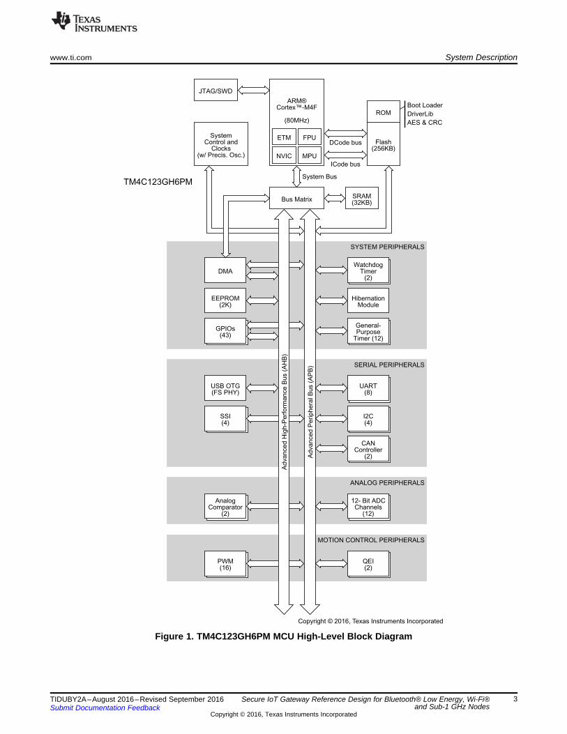
1.1 TM4C123GH6PMThe TM4C123GH6PM MCU is targeted for industrial applications including the following: remotemonitoring, electronic point-of-sale machines, test equipment, measurement equipment, networkappliances, switches, factory automation, HVAC, building control, gaming equipment, motion control,transportation, and security.
The TM4C123GH6PM is an 80-MHz high-performance MCU with up to 256KB on-chip Flash and 32KBon-chip SRAM. There are up to 43 GPIOs with programmable control for GPIO interrupts, padconfiguration, and pin muxing. The MCU is integrated with six 32-bit general-purpose timers (up to twelve16-bit timers), eight UARTs, four synchronous serial interface (SSI) modules, four inter-integrated circuit(I2C) modules, two 12-bit analog-to-digital converters (ADCs) with 12 analog input channels and a samplerate of one million samples per second, eight pulse width modulation (PWM) generator blocks, and twoquadrature encoder interface (QEI) modules. The on-chip universal serial bus (USB) controller supportsthe USB OTG/Host/Device modes. The ARM® PrimeCell 32-channel configurable μDMA controller is alsointegrated to provide a method to offload data transfer tasks from the Cortex®-M4 processor and toefficiently use the processor and the bus bandwidth.
ARM®Cortex™-M4F
(80MHz)
NVIC MPU
FPUETMFlash
(256KB)
Boot Loader
DriverLib
AES & CRC
ROM
DCode bus
ICode bus
JTAG/SWD
SystemControl and
Clocks(w/ Precis. Osc.)
Bus Matrix
System Bus
SRAM(32KB)
SYSTEM PERIPHERALS
WatchdogTimer
(2)DMA
HibernationModule
EEPROM(2K)
General-Purpose
Timer (12)
GPIOs(43)
SERIAL PERIPHERALS
UART(8)
USB OTG(FS PHY)
I2C(4)
SSI(4)
CANController
(2)
ANALOG PERIPHERALS
12- Bit ADCChannels
(12)
AnalogComparator
(2)
MOTION CONTROL PERIPHERALS
QEI(2)
PWM(16)
Ad
va
nce
dP
erip
he
ralB
us
(AP
B)
Ad
va
nce
dH
igh
-Pe
rfo
rma
nce
Bu
s(A
HB
)
TM4C123GH6PM
Copyright © 2016, Texas Instruments Incorporated
www.ti.com System Description
3TIDUBY2A–August 2016–Revised September 2016Submit Documentation Feedback
Copyright © 2016, Texas Instruments Incorporated
Secure IoT Gateway Reference Design for Bluetooth® Low Energy, Wi-Fi®and Sub-1 GHz Nodes
Figure 1. TM4C123GH6PM MCU High-Level Block Diagram

System Description www.ti.com
4 TIDUBY2A–August 2016–Revised September 2016Submit Documentation Feedback
Copyright © 2016, Texas Instruments Incorporated
Secure IoT Gateway Reference Design for Bluetooth® Low Energy, Wi-Fi®and Sub-1 GHz Nodes
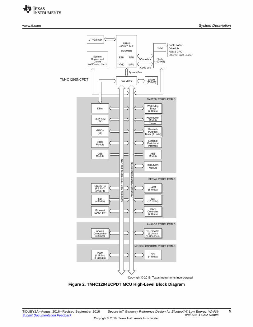
1.2 TM4C1294NCPDTThe TM4C1294ECPDT is a 120-MHz high-performance MCU with a 1MB on-chip Flash and 256KB on-chip SRAM and features an integrated Ethernet MAC+PHY for connected applications. The device hashigh-bandwidth interfaces like a memory controller and a high-speed USB2.0 digital interface. Integratinga number of low- to mid-speed serials, up to a 4MSPS 12-bit ADC, and motion control peripherals, thisdevice makes for a unique solution for a variety of applications ranging from industrial communicationequipment to Smart Energy or Smart Grid applications. The TM4C129ENCPDT MCU is code-compatibleto all members of the extensive Tiva™ C Series, providing flexibility to fit precise needs.
This MCU is hardware encryption enabled. It provides security by its CRC hardware, AES hardware-accelerated data encryption, DES block cipher implementation, hashing hardware accelerator, and fourtamper units along with tamper event response. Therefore, the TM4C1294ECPDT is ideally suited fordeveloping secure cloud connected IoT systems to assist factory control or automation systems.
TM4C129ENCPDT
ARM®Cortex™-M4F
(120MHz)
NVIC MPU
FPUETMFlash
(1024KB)
Boot Loader
DriverLib
AES & CRC
Ethernet Boot Loader
ROM
DCode bus
ICode bus
JTAG/SWD
SystemControl and
Clocks(w/ Precis. Osc.)
Bus Matrix
System Bus
SRAM(256KB)
SYSTEM PERIPHERALS
WatchdogTimer
(2 Units)DMA
HibernationModule
Tamper
EEPROM(6K)
General-Purpose
Timer (8 Units)
GPIOs(90)
ExternalPeripheralInterface
CRCModule
AESModule
DESModule
SHA/MD5Module
SERIAL PERIPHERALS
UART(8 Units)
USB OTG(FS PHYor ULPI)
I2C(10 Units)
SSI(4 Units)
CANController(2 Units)
EthernetMAC/PHY
ANALOG PERIPHERALS
12- Bit ADC(2 Units /
20 Channels)
AnalogComparator
(3 Units)
MOTION CONTROL PERIPHERALS
QEI(1 Units)
PWM(1 Units /8 Signals)
Ad
va
nce
dP
erip
he
ralB
us
(AP
B)
Ad
va
nce
dH
igh
-Pe
rfo
rma
nce
Bu
s(A
HB
)
Copyright © 2016, Texas Instruments Incorporated
www.ti.com System Description
5TIDUBY2A–August 2016–Revised September 2016Submit Documentation Feedback
Copyright © 2016, Texas Instruments Incorporated
Secure IoT Gateway Reference Design for Bluetooth® Low Energy, Wi-Fi®and Sub-1 GHz Nodes
Figure 2. TM4C1294ECPDT MCU High-Level Block Diagram

Copyright © 2016, Texas Instruments Incorporated
DRV8833
Stepper or bushed DC motor driver
Con
trol
ler
nSLEEP
PWM
nFAULT
M1.5 A
1.5 A
+
+ ±
±
2.7 to 10.8 V
System Description www.ti.com
6 TIDUBY2A–August 2016–Revised September 2016Submit Documentation Feedback
Copyright © 2016, Texas Instruments Incorporated
Secure IoT Gateway Reference Design for Bluetooth® Low Energy, Wi-Fi®and Sub-1 GHz Nodes
1.3 DRV8833The DRV8833 has two H-bridge drivers to drive a bipolar stepper motor, two DC brush motors, or otherinductive loads. Aimed at driving 3.3-V and 5-V motors, this stepper driver with integrated FETs supportup to 1.5 ARMS with a low-power sleep mode to conserve power for battery-powered applications. Internalshutdown functions with a fault output pin protect the device from overcurrent, short-circuit, undervoltagelockout, and over temperature.
Figure 3. DRV833 Functional Block Diagram

RAM
ROM
HO
ST
I/F
SPI
UART
SY
ST
EM
Oscillators
DC-DC
BAT Monitor
Baseband
Radio
Wi-Fi Driver
TCP/IP & TLS/SSL
Stacks
ARM Processor
MAC Processor
Crypto Engine
Syn
thesiz
er
PA
LNA
SWAS031-A
www.ti.com System Description
7TIDUBY2A–August 2016–Revised September 2016Submit Documentation Feedback
Copyright © 2016, Texas Instruments Incorporated
Secure IoT Gateway Reference Design for Bluetooth® Low Energy, Wi-Fi®and Sub-1 GHz Nodes
1.4 CC3100The CC3100 Wi-Fi network processor subsystem features a Wi-Fi Internet-on-a-chip™ integrated circuitand contains an additional dedicated ARM MCU that completely offloads the host MCU. This subsystemincludes an 802.11 b/g/n radio, baseband, and MAC with a powerful crypto engine for fast, secure Internetconnections with 256-bit encryption. The CC3100 supports Station, Access Point, and Wi-Fi Direct modes.The device also supportsWPA2 personal and enterprise security and WPS 2.0. This subsystem includesembedded TCP/IP and TLS/SSL stacks, HTTP server, and multiple Internet protocols.
Figure 4. CC3100 Hardware Overview

System Description www.ti.com
8 TIDUBY2A–August 2016–Revised September 2016Submit Documentation Feedback
Copyright © 2016, Texas Instruments Incorporated
Secure IoT Gateway Reference Design for Bluetooth® Low Energy, Wi-Fi®and Sub-1 GHz Nodes
1.5 CC2650The CC2650 is a cost-effective, ultra-low-power, 2.4-GHz RF wireless MCU targeting Bluetooth® Smart,ZigBee® and 6LoWPAN, and ZigBee RF4CE remote control applications. A very low active RF and MCUcurrent and low-power mode current consumption provides excellent battery lifetime, operates on smallcoin-cell batteries, and operates in energy-harvesting applications. The CC2650 contains a 32-bit ARMCortex-M3 running at 48 MHz as the main processor and has a rich peripheral feature set, including anultra-low-power sensor controller. The ultra-low-power sensor controller is ideal for interfacing externalsensors or collecting analog and digital data while the rest of the system is in sleep mode. The Bluetoothlow-energy (BLE) controller and the IEEE 802.15.4 MAC are embedded into ROM and are runningpartially on a separate ARM Cortex-M0 processor. This architecture improves overall system performanceand power consumption and frees up flash memory for the application.
Figure 5. CC2650 Architectural Overview

www.ti.com System Description
9TIDUBY2A–August 2016–Revised September 2016Submit Documentation Feedback
Copyright © 2016, Texas Instruments Incorporated
Secure IoT Gateway Reference Design for Bluetooth® Low Energy, Wi-Fi®and Sub-1 GHz Nodes
1.6 BLE SensorTagThe SensorTag includes 10 low-power MEMS sensors in a tiny red package. It is expandable withDevPacks to make it easy to add more sensors or actuators. It can be connected to the cloud withBluetooth Smart and sensor data is online in 3 minutes. The SensorTag is based on the CC2650 wirelessMCU, offering 75% lower power consumption than previous Bluetooth Smart products. This allows theSensorTag to be battery powered and offer years of battery lifetime from a single coin cell battery. TheBluetooth Smart SensorTag includes iBeacon technology, which allows a phone to launch applicationsand customize content based on SensorTag data and physical location. Additionally, the SensorTag canbe enabled with ZigBee®/6LoWPAN technology.
Figure 6. BLE SensorTag With Coin Cell Battery
Figure 7. BLE SensorTag Internals (CC2650 Along With Sensors)

SimpleLink TM CC1310A Wireless MCU
Main CPU:
32-, 64-, 128-KBFlash
Sensor Controller
cJTAG
20-KBSRAM
ROM
ARM®
Cortex ®-M3
DC-DC Converter
RF core
ARM®
Cortex ®-M0
DSP Modem
4-KB SRAM
ROM
Sensor Controller Engine
2x Analog Comparators
12-Bit ADC, 200ks/s
Constant Current Source
SPI / I2C Digital Sensor IF
2-KB SRAM
Time-to-Digital Converter
General Peripherals / Modules
2x SSI (SPI,µW,TI)
Watchdog Timer
Temp. / Batt. Monitor
RTC
I2C
UART
I2S
10 / 15 / 30 GPIOs
AES
32 ch. PDMA
ADC
ADC
Digital PLL
TRNG
8-KBCache
Copyright © 2016, Texas Instruments Incorporated
4x 32-Bit Timers
System Description www.ti.com
10 TIDUBY2A–August 2016–Revised September 2016Submit Documentation Feedback
Copyright © 2016, Texas Instruments Incorporated
Secure IoT Gateway Reference Design for Bluetooth® Low Energy, Wi-Fi®and Sub-1 GHz Nodes
1.7 CC1310The device is a member of the CC26xx and CC13xx family of cost-effective, ultra-low-power, 2.4-GHz andsub-1-GHz RF devices. Very low active RF, MCU current, and low-power mode current consumptionprovide excellent battery lifetime and allow operation on small coin-cell batteries and in energy-harvestingapplications. The CC1310 is the first part in a Sub-1GHz family of cost-effective, ultra-low-power wirelessMCUs. This device combines a flexible, very low-power RF transceiver with a powerful 48-MHz Cortex-M3MCU in a platform supporting multiple physical layers and RF standards. A dedicated radio controller(Cortex-M0) handles low-level RF protocol commands that are stored in ROM or RAM, thus ensuring ultra-low power and flexibility. The low-power consumption of the CC1310 does not come at the expense of RFperformance; the CC1310 has excellent sensitivity and robustness (selectivity and blocking) performance.
Figure 8. CC1310 Functional Block Diagram

www.ti.com System Description
11TIDUBY2A–August 2016–Revised September 2016Submit Documentation Feedback
Copyright © 2016, Texas Instruments Incorporated
Secure IoT Gateway Reference Design for Bluetooth® Low Energy, Wi-Fi®and Sub-1 GHz Nodes
1.8 TRF7970AThe TRF7970A is an integrated analog front-end and data-framing device for a 13.56-MHz RFID and nearfield communication (NFC) system. Built-in programming options make the device suitable for a widerange of applications for proximity and vicinity identification systems. The device can perform in one ofthree modes: RFID and NFC reader, NFC peer, or in card emulation mode. Built-in user-configurableprogramming options make the device suitable for a wide range of applications. The TRF7970A device isconfigured by selecting the desired protocol in the control registers. Direct access to all control registersallows fine tuning of various reader parameters as needed.
1.9 RF430CL330HThe Texas Instruments Dynamic NFC Interface Transponder RF430CL330H is an NFC Tag Type 4 devicethat combines a wireless NFC interface and a wired SPI or I2C interface to connect the device to a host.The NDEF message in the SRAM can be written and read from the integrated SPI or I2C serialcommunication interface and can also be accessed and updated wirelessly through the integratedISO14443B-compliant RF interface that supports up to 848 kbps. This operation allows NFC connectionhandover for an alternative carrier like BLE and Wi-Fi as an easy and intuitive pairing process orauthentication process with only a tap. As a general NFC interface, the RF430CL330H enables endequipments to communicate with the fast-growing infrastructure of NFC-enabled smart phones, tablets,and notebooks.
1.10 TM4C123 Swizzle Adapter BoardThe TM4C123 swizzle adapter board is a special purpose hardware adapter board to interface theTM4C123x LaunchPad with NFC and Wi-Fi BoosterPacks along with rendering necessary PWM outputsfor the DRV8833 motor drive. Inorder to accommodate PWM pins, instead of using default TM4C123SPI2, SPI0 is used to communicate to CC3100, hence CC3100 Booster pack cannot be mounted directly.Swizzle adapter board reroutes SPI0 lines to SPI2 position on a different header to facilitate CC3100mounting, this can be done manually through Jumper wires too.
Figure 9. TM4C123 Swizzle Adapter Board

DRV8833
AOUT1
AOUT2
BOUT2
BOUT1
AIN1
AIN2
BIN1
BIN2
1 step
System Description www.ti.com
12 TIDUBY2A–August 2016–Revised September 2016Submit Documentation Feedback
Copyright © 2016, Texas Instruments Incorporated
Secure IoT Gateway Reference Design for Bluetooth® Low Energy, Wi-Fi®and Sub-1 GHz Nodes
1.11 ExositeExosite is Internet of Things (IoT) software as a service (SaaS) company that develops software forcompanies that view and analyze data collected from sensors built into physical objects. Exosite's mostbasic concept is to make internet-connected physical things useful to people and businesses. Exosite'sproducts help developers, companies, and organizations build IoT product solutions by providing pieces ofthe IoT system, including device code, a device connectivity and application platform, and hostedapplications and services.
To get acquainted quickly with the way TM4C devices communicate with the Exosite, go through the"qs_iot" example project available in the TivaWare™. It requires the user to sign-up or log into thewww.ti.exosite.com portal and then register the device on the server so that the device can be identifiedsecurely by the server and further communication can take place.
1.12 Stepper Motor ControlA stepper motor is a brushless DC electric motor that divides a full rotation into a number of equal steps.The motor's position can then be commanded to move and hold at one of these steps without feedback.The stepper motor is widely used in a wide range of applications involving precision motion control.
Figure 10. Driving the Stepper Motor in Full-Step Mode
www.ti.com Getting Started Hardware
13TIDUBY2A–August 2016–Revised September 2016Submit Documentation Feedback
Copyright © 2016, Texas Instruments Incorporated
Secure IoT Gateway Reference Design for Bluetooth® Low Energy, Wi-Fi®and Sub-1 GHz Nodes
2 Getting Started Hardware
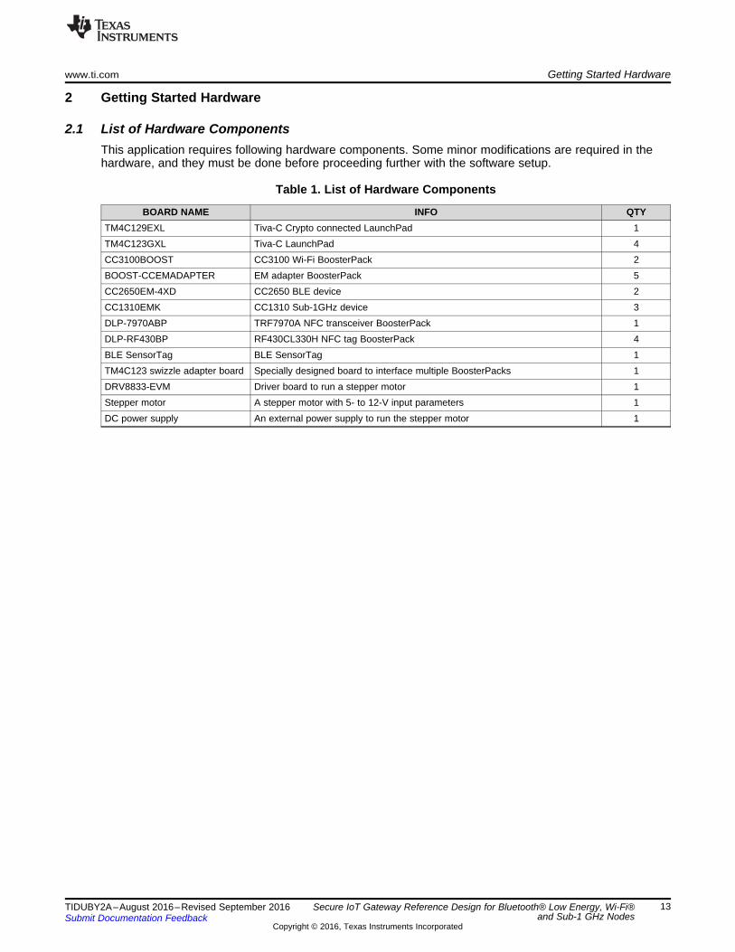
2.1 List of Hardware ComponentsThis application requires following hardware components. Some minor modifications are required in thehardware, and they must be done before proceeding further with the software setup.
Table 1. List of Hardware Components
BOARD NAME INFO QTYTM4C129EXL Tiva-C Crypto connected LaunchPad 1TM4C123GXL Tiva-C LaunchPad 4CC3100BOOST CC3100 Wi-Fi BoosterPack 2BOOST-CCEMADAPTER EM adapter BoosterPack 5CC2650EM-4XD CC2650 BLE device 2CC1310EMK CC1310 Sub-1GHz device 3DLP-7970ABP TRF7970A NFC transceiver BoosterPack 1DLP-RF430BP RF430CL330H NFC tag BoosterPack 4BLE SensorTag BLE SensorTag 1TM4C123 swizzle adapter board Specially designed board to interface multiple BoosterPacks 1DRV8833-EVM Driver board to run a stepper motor 1Stepper motor A stepper motor with 5- to 12-V input parameters 1DC power supply An external power supply to run the stepper motor 1

1
2
Getting Started Hardware www.ti.com
14 TIDUBY2A–August 2016–Revised September 2016Submit Documentation Feedback
Copyright © 2016, Texas Instruments Incorporated
Secure IoT Gateway Reference Design for Bluetooth® Low Energy, Wi-Fi® andSub-1 GHz Nodes
2.2 Hardware Configuration
2.2.1 Gateway
2.2.1.1 Setting up Gateway HardwareThe hardware components required to setup the gateway are listed in Table 2:
Table 2. Gateway Hardware Setup
SR NO COMPONENT NAME
1 TM4C129EXL Crypto Connected LaunchPadNo modifications are required.
2
CC3100 Wi-Fi BoosterPackMandatory configurations on the BoosterPack are as shown in Figure 11. Follow these steps:1. Remove the two 0-Ω resistors as shown in Figure 11. These resistors are connected to the RX and TX pins on
the BoosterPack header P1. Removing them ensures that the CC3100 does not interfere with its TX and RXpins.
2. Change the jumper J-8 setting to MCU.
Figure 11. Hardware Configuration of CC3100 BoosterPack on Gateway
3 CC2650EM BLE DeviceNo modifications are required.
4 CC1310EM Sub-1GHz DeviceNo modifications are required.

1
2
www.ti.com Getting Started Hardware
15TIDUBY2A–August 2016–Revised September 2016Submit Documentation Feedback
Copyright © 2016, Texas Instruments Incorporated
Secure IoT Gateway Reference Design for Bluetooth® Low Energy, Wi-Fi®and Sub-1 GHz Nodes
Table 2. Gateway Hardware Setup (continued)SR NO COMPONENT NAME
5
EM Adapter BoosterPack (Two Numbers)
NOTE: Two BoosterPacks are required to connect to BLE and Sub-1GHz devices.Both follow the same configuration. In fact, all the EM adapter BoosterPacksused in this entire application demo follow same hardware configuration.
Mandatory configurations on the BoosterPacks are as shown in Figure 12. Follow these steps:
1. Remove all the 0-Ω resistors R-2 to R-20 except R-3 and R-4 as shown in Figure 12.2. Connect the inner R-18 junction with the outer R-15 junction as shown in Figure 12. This
change connects the TM4C and CC2650 and CC1310 RESET pins.
Figure 12. Hardware Configuration of EM Adapter BoosterPack on Gateway
NOTE: The RESET pin of the EM Adapter BoosterPack is not aligned with theRESET pin of the TM4C1294EXL on BoosterPack-1. Hence, hard-wire theRESET pin to avoid unknown observations.
6
TRF7970A NFC Transceiver BoosterPackMandatory configurations on the BoosterPack are as shown in Figure 13. Follow these steps:1. Solder a 0-Ω resistor to connect the IRQ junction to the adjacent junction numbered as "2" as shown in
Figure 13.
Figure 13. Hardware Configuration of TRF7970A BoosterPack on Gateway

Getting Started Hardware www.ti.com
16 TIDUBY2A–August 2016–Revised September 2016Submit Documentation Feedback
Copyright © 2016, Texas Instruments Incorporated
Secure IoT Gateway Reference Design for Bluetooth® Low Energy, Wi-Fi®and Sub-1 GHz Nodes
2.2.1.2 BoosterPack Signal MappingThe header connections for setting up the gateway are shown in the following tables. Refer to these tablesafter programming all the hardware components with the necessary binaries.
(1) The RESET pin of the EM Adapter BoosterPack is not aligned with the RESET pin of the TM4C1294EXL on Boosterpack-1.Hence, hard-wire the RESET pin to avoid unknown observations.
Table 3. BoosterPack-1 Signal Mapping
BOOSTERPACKCONNECTOR
TM4C1294 CRYPTOCLP
EM ADAPTERBOOSTERPACK CC2650EM TRF7970A NFC
BOOSTERPACKA1-1 3.3 V VDD_LP VDD 1 (VDD)A1-2 PE4 Unused Unused 2 (Unused)A1-3 PC4_U7RX LP1.3 RF1.09 3 (Unused)A1-4 PC5_U7TX LP1.4 RF1.07 4 (Unused)A1-5 PC6 Unused Unused 5 (Unused)A1-6 PE5 Unused Unused 6 (Unused)A1-7 PD3_SSI2CLK Unused Unused 7 (Unused)A1-8 PC7 Unused Unused 8 (IRQ)A1-9 PB2 Unused Unused 9 (SS)A1-10 PB3 Unused Unused 10 (EN)D1-1 GND GND GND 20 (GND)D1-2 PM3 Unused Unused 19 (Unused)D1-3 PH2 Unused Unused 18 (Unused)D1-4 PH3 Unused Unused 17 (Unused)D1-5 RESET RESET (1) RF2.15 (RESET) 16 (RESET)D1-6 PD1_I2C7SDA Unused Unused 15 (MOSI)D1-7 PD0_I2C7SCl Unused Unused 14 (MISO)D1-8 PN2 Unused Unused 13 (Unused)D1-9 PN3 Unused Unused 12 (Unused)D1-10 PP2 Unused Unused 11 (Unused)
www.ti.com Getting Started Hardware
17TIDUBY2A–August 2016–Revised September 2016Submit Documentation Feedback
Copyright © 2016, Texas Instruments Incorporated
Secure IoT Gateway Reference Design for Bluetooth® Low Energy, Wi-Fi®and Sub-1 GHz Nodes
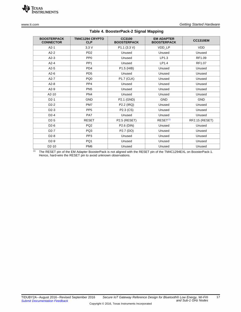
(1) The RESET pin of the EM Adapter BoosterPack is not aligned with the RESET pin of the TM4C1294EXL on BoosterPack-1.Hence, hard-wire the RESET pin to avoid unknown observations.
Table 4. BoosterPack-2 Signal Mapping
BOOSTERPACKCONNECTOR
TM4C1294 CRYPTOCLP
CC3100BOOSTERPACK
EM ADAPTERBOOSTERPACK CC1310EM
A2-1 3.3 V P1.1 (3.3 V) VDD_LP VDDA2-2 PD2 Unused Unused UnusedA2-3 PP0 Unused LP1.3 RF1.09A2-4 PP1 Unused LP1.4 RF1.07A2-5 PD4 P1.5 (HIB) Unused UnusedA2-6 PD5 Unused Unused UnusedA2-7 PQ0 P1.7 (CLK) Unused UnusedA2-8 PP4 Unused Unused UnusedA2-9 PN5 Unused Unused UnusedA2-10 PN4 Unused Unused UnusedD2-1 GND P2.1 (GND) GND GNDD2-2 PM7 P2.2 (IRQ) Unused UnusedD2-3 PP5 P2.3 (CS) Unused UnusedD2-4 PA7 Unused Unused UnusedD2-5 RESET P2.5 (RESET) RESET (1) RF2.15 (RESET)D2-6 PQ2 P2.6 (DIN) Unused UnusedD2-7 PQ3 P2.7 (DO) Unused UnusedD2-8 PP3 Unused Unused UnusedD2-9 PQ1 Unused Unused UnusedD2-10 PM6 Unused Unused Unused

Getting Started Hardware www.ti.com
18 TIDUBY2A–August 2016–Revised September 2016Submit Documentation Feedback
Copyright © 2016, Texas Instruments Incorporated
Secure IoT Gateway Reference Design for Bluetooth® Low Energy, Wi-Fi®and Sub-1 GHz Nodes
2.2.2 Wi-Fi Node
2.2.2.1 Setting up Wi-Fi Node HardwareThe hardware components required to setup the Wi-Fi node are listed in Table 5:
Table 5. Wi-Fi Node Hardware Setup
SR NO COMPONENT NAME
1 TM4C123GXL LaunchPadNo modifications are required.
2 CC3100 Wi-Fi BoosterPackChange the jumper J-8 setting to MCU.
3
RF430CL330H BoosterPackMandatory configurations on the BoosterPack are as shown in Figure 14. Follow this step:1. Remove the 0-Ω resistor at R-8 and place a 0-Ω resistor at R-9 as shown in Figure 14.
Figure 14. Hardware Configuration of TRF7970A BoosterPack on Wi-Fi Node
4 TM4C123 Swizzle Adapter BoardNo modifications are required.
5 DRV8833 Stepper Motor Driver BoardNo modifications are required.
6 Stepper MotorNo modifications are required.
7 External Power Supply (5 to 12 V)No modifications are required.

www.ti.com Getting Started Hardware
19TIDUBY2A–August 2016–Revised September 2016Submit Documentation Feedback
Copyright © 2016, Texas Instruments Incorporated
Secure IoT Gateway Reference Design for Bluetooth® Low Energy, Wi-Fi®and Sub-1 GHz Nodes
2.2.2.2 Wi-Fi Node Signal MappingThe header connections for setting up the Wi-Fi node are shown in the following tables. Refer to thesetables after programming all the hardware components with the necessary binaries.
Table 6. Wi-Fi Node Signal Mapping
BOOSTERPACKCONNECTOR
CC3100 BOOSTERPACK(WI-FI) DLP-RF430BP (NFC) TM4C123 LAUNCHPAD
CONNECTORP1-1 3.3 V 3.0 V J1-1: 3.3 VP1-2 Open Unused OpenP1-3 CC_UART1_TX Unused J1-3: PB0_U1RXP1-4 CC_UART1_RX Unused J1-4: PB1_U1TXP1-5 CC_nHIB Unused J3-7: PE1P1-6 Open Unused J3-8: PE2P1-7 CC_SPI_CLK DATA_CLK J2-10: PA2 _SSI0CLKP1-8 Open RESET J3-3: PD0P1-9 Test_3 Unused J3-5: PD2
P1-10 FORCE_AP Unused J4-3: PB3P3-1 5 V N/A J3-1: 5VP3-2 GND N/A J3-2GNDP3-3 Open N/AP3-4 Open N/AP3-5 Open N/AP3-6 Open N/AP3-7 Open N/AP3-8 Open N/AP3-9 Open N/A
P3-10 Open N/AP4-1 Test_29 N/A J4-1: PF2P4-2 Test_30 N/A J4-2: PF3P4-3 Open N/AP4-4 CC_URT1_CTS N/A J2-4: PF0_U1RTSP4-5 CC_UART1_RTS N/A J3-10: PF1_U1CTSP4-6 Open N/AP4-7 CC_NWP_UART_TX N/A J4-6: PC6_U3RXP4-8 CC_WL_UART_TX N/A J1-5: PE4_U5RXP4-9 CC_WLRS232_RX N/A J4-9: PD7_U2TX
P4-10 CC_WLRS232_TX N/A J4-8: PD6_U2RXP2-1 GND GND J2-1: GNDP2-2 CC_IRQ Unused J3-6: PD3P2-3 CC_SPI_CS Unused J2-3: PE0P2-4 Open Unused OpenP2-5 MCU_RESET_IN Unused J2-5: RESET
P2-6 CC_SPI_DIN MOSI/SDA J1-8: PA5_SSI0TX,J1-10: PA7_I2C1SDA
P2-7 CC_SPI_DOUT MISO/SCL J2-8: PA4 _SSI0RXJ1-9:PA6_I2C1SCL
P2-8 Test_63 SPI_CS J1-7: PB4P2-9 Test_64 INTO J4-7: PC7
P2-10 Test_18 Unused J3-3: PD0
Swizzle board
Copyright © 2016, Texas Instruments Incorporated
TM4C123
CC3100RF430
DR
V8833
DRV8833
1
2
3
4
5
6
7
8
AIN1
AIN2
BIN2
BIN1
VDD
GND
AOUT1
AOUT2
BOUT1
BOUT2
Stepper motor
A
A
B
B
Getting Started Hardware www.ti.com
20 TIDUBY2A–August 2016–Revised September 2016Submit Documentation Feedback
Copyright © 2016, Texas Instruments Incorporated
Secure IoT Gateway Reference Design for Bluetooth® Low Energy, Wi-Fi®and Sub-1 GHz Nodes
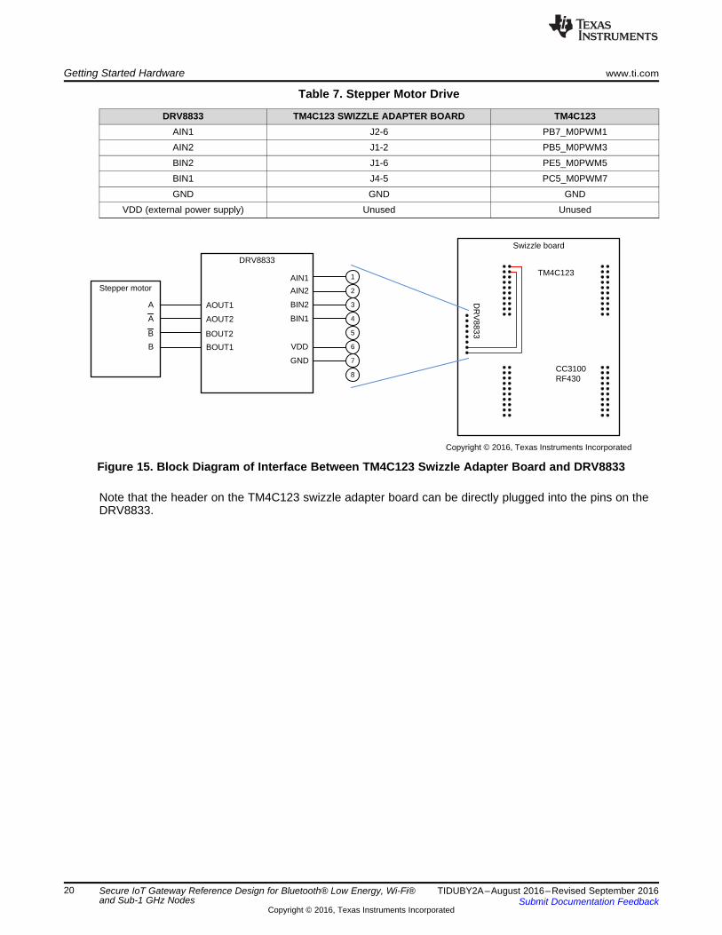
Table 7. Stepper Motor Drive
DRV8833 TM4C123 SWIZZLE ADAPTER BOARD TM4C123AIN1 J2-6 PB7_M0PWM1AIN2 J1-2 PB5_M0PWM3BIN2 J1-6 PE5_M0PWM5BIN1 J4-5 PC5_M0PWM7GND GND GND
VDD (external power supply) Unused Unused
Figure 15. Block Diagram of Interface Between TM4C123 Swizzle Adapter Board and DRV8833
Note that the header on the TM4C123 swizzle adapter board can be directly plugged into the pins on theDRV8833.

1
2
www.ti.com Getting Started Hardware
21TIDUBY2A–August 2016–Revised September 2016Submit Documentation Feedback
Copyright © 2016, Texas Instruments Incorporated
Secure IoT Gateway Reference Design for Bluetooth® Low Energy, Wi-Fi®and Sub-1 GHz Nodes
2.2.3 BLE Node
2.2.3.1 Setting up BLE Node HardwareThe hardware components required to setup the BLE node are listed in Table 8:
Table 8. BLE Node Hardware Setup
SR NO COMPONENT NAME
1 TM4C123GXL LaunchPadNo modifications are required.
2 CC2650EM BLE DeviceNo modifications are required.
3
EM Adapter BoosterPackMandatory configurations on the BoosterPacks are as shown in Figure 16. Follow these steps:1. Remove all the 0-Ω resistors R-2 to R-20 except R-3 and R-4 as shown in Figure 16..2. Connect the inner R-18 junction with the outer R-15 junction as shown in Figure 16. This change connects the
TM4C123 and CC2650 RESET pins.
Figure 16. Hardware Configuration of EM Adapter BoosterPack on BLE Node
NOTE: The RESET pin of the EM Adapter BoosterPack is not aligned with theRESET pin of the TM4C1294EXL on BoosterPack-1. Hence, hard-wire theRESET pin to avoid unknown observations.
4 RF430CL330H BoosterPackNo modifications are required.
Getting Started Hardware www.ti.com
22 TIDUBY2A–August 2016–Revised September 2016Submit Documentation Feedback
Copyright © 2016, Texas Instruments Incorporated
Secure IoT Gateway Reference Design for Bluetooth® Low Energy, Wi-Fi®and Sub-1 GHz Nodes
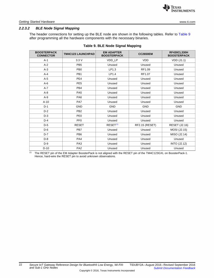
2.2.3.2 BLE Node Signal MappingThe header connections for setting up the BLE node are shown in the following tables. Refer to Table 9after programming all the hardware components with the necessary binaries.
(1) The RESET pin of the EM Adapter BoosterPack is not aligned with the RESET pin of the TM4C123GXL on BoosterPack-1.Hence, hard-wire the RESET pin to avoid unknown observations.
Table 9. BLE Node Signal Mapping
BOOSTERPACKCONNECTOR TM4C123 LAUNCHPAD EM ADAPTER
BOOSTERPACK CC2650EM RF430CL330HBOOSTERPACK
A-1 3.3 V VDD_LP VDD VDD (J1.1)A-2 PB5 Unused Unused UnusedA-3 PB0 LP1.3 RF1.09 UnusedA-4 PB1 LP1.4 RF1.07 UnusedA-5 PE4 Unused Unused UnusedA-6 PE5 Unused Unused UnusedA-7 PB4 Unused Unused UnusedA-8 PA5 Unused Unused UnusedA-9 PA6 Unused Unused UnusedA-10 PA7 Unused Unused UnusedD-1 GND GND GND GNDD-2 PB2 Unused Unused UnusedD-3 PE0 Unused Unused UnusedD-4 PF0 Unused Unused UnusedD-5 RESET RESET (1) RF2.15 (RESET) RESET (J2.16)D-6 PB7 Unused Unused MOSI (J2.15)D-7 PB6 Unused Unused MISO (J2.14)D-8 PA4 Unused Unused UnusedD-9 PA3 Unused Unused INTO (J2.12)D-10 PA2 Unused Unused Unused
1
2
www.ti.com Getting Started Hardware
23TIDUBY2A–August 2016–Revised September 2016Submit Documentation Feedback
Copyright © 2016, Texas Instruments Incorporated
Secure IoT Gateway Reference Design for Bluetooth® Low Energy, Wi-Fi®and Sub-1 GHz Nodes
2.2.4 Sub-1GHz Node
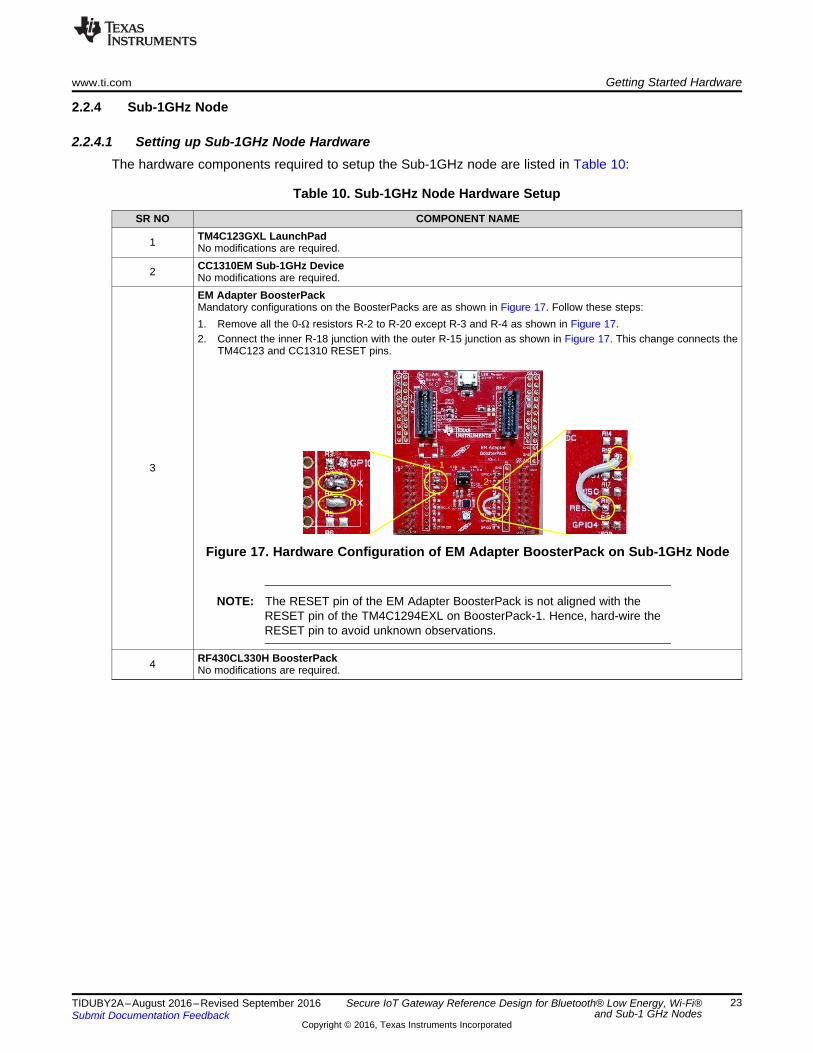
2.2.4.1 Setting up Sub-1GHz Node HardwareThe hardware components required to setup the Sub-1GHz node are listed in Table 10:
Table 10. Sub-1GHz Node Hardware Setup
SR NO COMPONENT NAME
1 TM4C123GXL LaunchPadNo modifications are required.
2 CC1310EM Sub-1GHz DeviceNo modifications are required.
3
EM Adapter BoosterPackMandatory configurations on the BoosterPacks are as shown in Figure 17. Follow these steps:1. Remove all the 0-Ω resistors R-2 to R-20 except R-3 and R-4 as shown in Figure 17.2. Connect the inner R-18 junction with the outer R-15 junction as shown in Figure 17. This change connects the
TM4C123 and CC1310 RESET pins.
Figure 17. Hardware Configuration of EM Adapter BoosterPack on Sub-1GHz Node
NOTE: The RESET pin of the EM Adapter BoosterPack is not aligned with theRESET pin of the TM4C1294EXL on BoosterPack-1. Hence, hard-wire theRESET pin to avoid unknown observations.
4 RF430CL330H BoosterPackNo modifications are required.

Getting Started Hardware www.ti.com
24 TIDUBY2A–August 2016–Revised September 2016Submit Documentation Feedback
Copyright © 2016, Texas Instruments Incorporated
Secure IoT Gateway Reference Design for Bluetooth® Low Energy, Wi-Fi®and Sub-1 GHz Nodes
2.2.4.2 Sub-1GHz Node Signal MappingThe header connections for setting up the Sub-1GHz node are shown in Table 11. Refer to Table 11 afterprogramming all the hardware components with the necessary binaries.
(1) The RESET pin of EM Adapter BoosterPack is not aligned with the RESET pin of the TM4C123GXL on BoosterPack-1. Hence,hard-wire the RESET pin to avoid unknown observations.
Table 11. Sub-1GHz Node Signal Mapping
BOOSTERPACKCONNECTOR TM4C123 LAUNCHPAD EM ADAPTER
BOOSTERPACK CC1310EM RF430CL330HBOOSTERPACK
A-1 3.3 V VDD_LP VDD VDD (J1.1)A-2 PB5 Unused Unused UnusedA-3 PB0 LP1.3 RF1.09 UnusedA-4 PB1 LP1.4 RF1.07 UnusedA-5 PE4 Unused Unused UnusedA-6 PE5 Unused Unused UnusedA-7 PB4 Unused Unused UnusedA-8 PA5 Unused Unused UnusedA-9 PA6 Unused Unused UnusedA-10 PA7 Unused Unused UnusedD-1 GND GND GND GNDD-2 PB2 Unused Unused UnusedD-3 PE0 Unused Unused UnusedD-4 PF0 Unused Unused UnusedD-5 RESET RESET (1) RF2.15 (RESET) RESET (J2.16)D-6 PB7 Unused Unused MOSI (J2.15)D-7 PB6 Unused Unused MISO (J2.14)D-8 PA4 Unused Unused UnusedD-9 PA3 Unused Unused INTO (J2.12)D-10 PA2 Unused Unused Unused

Copyright © 2016, Texas Instruments Incorporated
TM4C129x
Gateway main application
Interface API
BLE
NFC Sub 1 GHz
Wi-Fi
Exosite API
SSL NDK
TivaWare
TM4C129EXL CryptoFRQQHFWHG�/DXQFK3DG�
TM4C129x
Sub 1-GHz node application
EasyLink API
TI-RTOS
CC13xxWare
CC13xx BoosterPack
BLE
BLE central application
BLE stack
TI-RTOS
CC26xxWare
CC26xx BoosterPackUART UART
NFC
TRF7970A (NFC transceiver BoosterPack)
Wi-Fi
CC3100 BoosterPack
Service pack
I2C I2C
TI-RTOS
www.ti.com Getting Started Software
25TIDUBY2A–August 2016–Revised September 2016Submit Documentation Feedback
Copyright © 2016, Texas Instruments Incorporated
Secure IoT Gateway Reference Design for Bluetooth® Low Energy, Wi-Fi®and Sub-1 GHz Nodes
3 Getting Started Software
3.1 Gateway Software ArchitectureFigure 18 explains the architecture of the TM4C129x-based IoT gateway.
Figure 18. Gateway Software Architecture Diagram
TM4C129x software blocks:• TivaWare C: for TM4C hardware register access and serial communications to other hardware through
UART, SPI, and I2C.• Exosite API: a C language translation of the set of standard routines, which are required to connect
and communicate with the Exosite Cloud Server. This implementation internally uses NDK andwolfSSL libraries of TI-RTOS.
• Interface API: allows the TM4C129x to communicate to the BLE, Wi-Fi, and Sub-1GHz hardwaremounted on it using the onboard serial peripherals such as UART, SPI, and I2C.
• TI-RTOS: used for scheduling tasks, which handle communication with:– Hardware peripherals (BLE, Wi-Fi, Sub-1GHz)– Exosite– Command line interface

Getting Started Software www.ti.com
26 TIDUBY2A–August 2016–Revised September 2016Submit Documentation Feedback
Copyright © 2016, Texas Instruments Incorporated
Secure IoT Gateway Reference Design for Bluetooth® Low Energy, Wi-Fi®and Sub-1 GHz Nodes
BLE software blocks:• TI-RTOS: for general scheduling
– Manages the command and response handling over the UART– Operates the BLE peripheral
• CC26xxWare: performs CC26xx hardware access and the UART operation• BLE stack: supports the BLE protocol
Sub-1GHz software blocks:• TI-RTOS: for general scheduling
– Manages the command and response handling over the UART– Operates the Sub-1GHz peripheral
• CC13xxWare: performs CC13xx hardware access and the UART operation• EasyLink API: supports the Sub-1GHz protocol
Wi-Fi software blocks:• There is no specific software required to be run on the CC3100 Wi-Fi module. However, for the sake of
maintaining uniformity across platforms, the CC3100 is programmed with the latest CC3100SDK-SERVICEPACK.
NFC software blocks:• There are no NFC software blocks in this design.

Copyright © 2016, Texas Instruments Incorporated
TM4C123x
Node main application
Interface API
NFC
Wi-Fi
TI-RTOS
TivaWare
TM4C123(;/�/DXQFK3DG�UART UART
NFC
TRF7970A (NFC transceiver BoosterPack)
Wi-Fi
CC3100 BoosterPack
Service pack
Swizzle board
DRV8833 Stepper motor
www.ti.com Getting Started Software
27TIDUBY2A–August 2016–Revised September 2016Submit Documentation Feedback
Copyright © 2016, Texas Instruments Incorporated
Secure IoT Gateway Reference Design for Bluetooth® Low Energy, Wi-Fi®and Sub-1 GHz Nodes
3.2 Wi-Fi Node Software ArchitectureFigure 19 shows the software architecture of the Wi-Fi node and slave.
Figure 19. Wi-Fi Node Software Architecture
TM4C123x software blocks:• TivaWare C: allows for TM4C hardware register access and serial communications to other hardware
through SPI. Also, it controls the PWM signals from the onboard PWM modules, which are used todrive the motor.
• Interface API: allows the TM4C123x to communicate to the Wi-Fi, NFC hardware mounted on it usingthe onboard SPI
• TI-RTOS: for scheduling tasks, which handle communication with– Hardware peripherals (Wi-Fi, NFC)– Motor drive, sending desired PWM signals– Command line interface
Wi-Fi software blocks:• There is no specific software required to be run on the CC3100 Wi-Fi module. However, for the sake of
maintaining uniformity across platforms, the CC3100 is programmed with the service pack.
NFC software blocks:• There are no NFC software blocks in this design.
Copyright © 2016, Texas Instruments Incorporated
TM4C129x
Gateway main application
Interface API
BLE
NFC Sub 1 GHz
Wi-Fi
Exosite API
SSL NDK
TivaWare
TM4C129EXL CryptoFRQQHFWHG�/DXQFK3DG�
BLE
BLE central application
BLE stack
TI-RTOS
CC26xxWare
CC26xx BoosterPackUART
NFC
TRF7970A (NFC transceiver BoosterPack)
I2C
TI-RTOS
Getting Started Software www.ti.com
28 TIDUBY2A–August 2016–Revised September 2016Submit Documentation Feedback
Copyright © 2016, Texas Instruments Incorporated
Secure IoT Gateway Reference Design for Bluetooth® Low Energy, Wi-Fi®and Sub-1 GHz Nodes
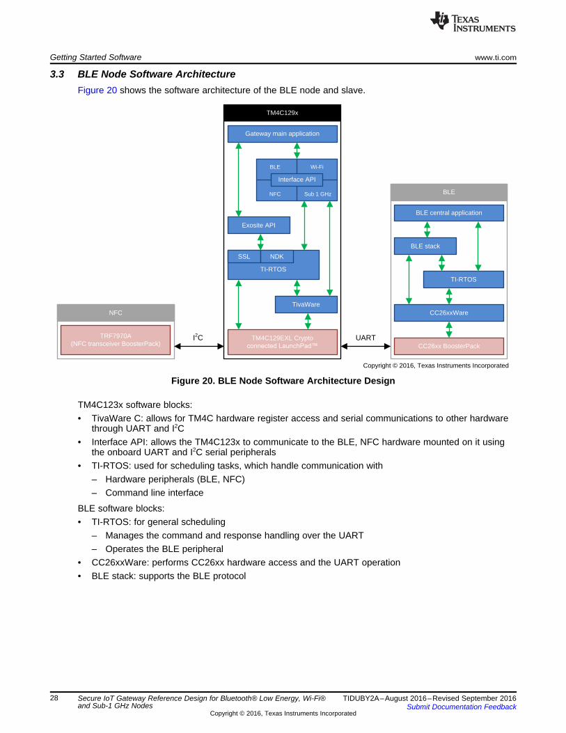
3.3 BLE Node Software ArchitectureFigure 20 shows the software architecture of the BLE node and slave.
Figure 20. BLE Node Software Architecture Design
TM4C123x software blocks:• TivaWare C: allows for TM4C hardware register access and serial communications to other hardware
through UART and I2C• Interface API: allows the TM4C123x to communicate to the BLE, NFC hardware mounted on it using
the onboard UART and I2C serial peripherals• TI-RTOS: used for scheduling tasks, which handle communication with
– Hardware peripherals (BLE, NFC)– Command line interface
BLE software blocks:• TI-RTOS: for general scheduling
– Manages the command and response handling over the UART– Operates the BLE peripheral
• CC26xxWare: performs CC26xx hardware access and the UART operation• BLE stack: supports the BLE protocol

Copyright © 2016, Texas Instruments Incorporated
TM4C129x
Gateway main application
Interface API
BLE
NFC Sub 1 GHz
Wi-Fi
Exosite API
SSL NDK
TivaWare
TM4C123*;/�/DXQFK3DG�
Sub 1 GHz
Sub 1-GHz node application
EasyLink API
TI-RTOS
CC13xxWare
CC13xx BoosterPackUART
NFC
TRF7970A (NFC transceiver BoosterPack)
I2C
TI-RTOS
www.ti.com Getting Started Software
29TIDUBY2A–August 2016–Revised September 2016Submit Documentation Feedback
Copyright © 2016, Texas Instruments Incorporated
Secure IoT Gateway Reference Design for Bluetooth® Low Energy, Wi-Fi®and Sub-1 GHz Nodes
3.4 Sub-1GHz Node Software ArchitectureFigure 21 shows the software architecture of the BLE node and slave.
Figure 21. Sub-1GHz Node Software Architecture Design
TM4C123x software blocks:• TivaWare C: allows for TM4C hardware register access and serial communications to other hardware
through UART and I2C• Interface API: allows the TM4C123x to communicate to the Sub-1GHz, NFC hardware mounted on it
using the on-board UART and I2C serial peripherals• TI-RTOS: used for scheduling tasks, which handle communication with
– Hardware peripherals (Sub-1GHz, NFC)– Command line interface
Sub-1GHz software blocks:• TI-RTOS: for general scheduling
– Manages the command and response handling over the UART– Operates the Sub-1GHz peripheral
• CC13xxWare: performs CC13xx hardware access and the UART operation• EasyLink API: supports the Sub-1GHz protocol

Getting Started Software www.ti.com
30 TIDUBY2A–August 2016–Revised September 2016Submit Documentation Feedback
Copyright © 2016, Texas Instruments Incorporated
Secure IoT Gateway Reference Design for Bluetooth® Low Energy, Wi-Fi® andSub-1 GHz Nodes
3.5 Exosite Architecture
3.5.1 SSL/TLS SecurityThe gateway connects to the Exosite using TI-RTOS NDK. This connection is secured using wolfSSL TLSroutines.
3.5.2 Exosite CIK InfrastructureThe TM4C crypto connected LaunchPad EK-TM4C129EXL, which is used as a gateway for this demo,has to be registered on TI's Exosite portal as explained in Section 5.2. When a device is registered withExosite, that device is allotted a CIK, which is a unique identifier of that device. Only a device having avalid CIK can connect to the Exosite cloud and exchange data.
3.5.3 Data Exchange MechanismExosite can store the values in the form of dataports on the server. These dataports are basically theserver’s version of variables. The widgets on the portal dashboard (Exosite GUI) are used to modify thesedataports or to display the value of these dataports on the same GUI.
The gateway periodically synchronizes with the cloud to achieve the following:• Uploading local variables' values to the intended dataports on the Exosite server. These local variables
contain the SensorTag data or data from BLE and Sub-1GHz nodes.• Downloading the values of the intended dataports and copying them into local variables. Based on the
values received from Exosite, a specific command is sent to the appropriate Wi-Fi or BLE. Sub-1GHznodes to toggle LEDs, control motor, LED blinking rate, and so on.
Table 12. Dataports Used
NODE DATAPORT NAME DATAPORT VALUE FORMAT
Wi-Fi nodewifi_node1_e2g
LED2MOD1DIR1SPD30MSV100RFS100RUN2:• LED—Toggle LED on Wi-Fi node (1: ON, 2: OFF)• MOD—Change Mode for stepper motor (1: Full-step, 2: Half-step, 3: Micro-step)• DIR—Change direction of stepper motor (1: Clockwise, 2: Counter-clockwise)• SPD—Change the speed of stepper motor. (1 to 100)%• MSV—Provide the value of microsteps if mode is "micro-stepping" (1 to 255)• RFS—Value of fixed number of steps if it is run as such. [1-999]• RUN—Choose if the motor is run freely or for fixed no of steps (1: Run freely, 2:
Stop, 3: Run for fixed no of steps, 4: Run for fixed no of steps and reverse)wifi_node1_g2e 1: Connected to gateway, 0: Disconnected
BLE SensorTag
ble_sentag_e2g 1: Connected to gateway, 2: Disconnected
ble_sentag_g2e
CON0AMT0.000IRT0.000HUM0.000BAR0.00LUX0.000• CON—Connection status (1: Connected to gateway, 0: Disconnected)• AMT—Ambient temperature value• IRT—IR temperature value• HUM—Humidity value• BAR—Atmospheric pressure value• LUX—Luminosity value
BLE node
ble_node1_e2gLDB2ANM30:
• LDB—Toggle LED on BLE node (1: ON, 2: OFF)• ANM—Change LED blinking rate (1 to 100)%
ble_node1_g2e
CON0BTA0BTB0TMC0TMF0:• CON—Connection with gateway status (1: Connected, 0: Disconnected)• BTA—Button1 press count• BTB—Button2 press count• TMC—Junction temperature in Celsius• TMF—Junction temperature in Fahrenheit

www.ti.com Getting Started Software
31TIDUBY2A–August 2016–Revised September 2016Submit Documentation Feedback
Copyright © 2016, Texas Instruments Incorporated
Secure IoT Gateway Reference Design for Bluetooth® Low Energy, Wi-Fi®and Sub-1 GHz Nodes
Table 12. Dataports Used (continued)NODE DATAPORT NAME DATAPORT VALUE FORMAT
Sub-1GHz node 1
sub_node1_e2gLDB2ANM30:
• LDB—Toggle LED on BLE node (1: ON, 2: OFF)• ANM—Change LED blinking rate (1 to 100)%
sub_node1_g2e
CON0BTA0BTB0TMC0TMF0:• CON—Connection with gateway status (1: Connected, 0: Disconnected)• BTA—Button1 press count• BTB—Button2 press count• TMC—Junction temperature in Celsius• TMF—Junction temperature in Fahrenheit
Sub-1GHz node 2
sub_node2_e2gLDB2ANM30:
• LDB—Toggle LED on BLE node (1: ON, 2: OFF)• ANM—Change LED blinking rate (1 to 100)%
sub_node2_g2e
CON0BTA0BTB0TMC0TMF0:• CON—Connection with gateway status (1: Connected, 0: Disconnected)• BTA—Button1 press count• BTB—Button2 press count• TMC—Junction temperature in Celsius• TMF—Junction temperature in Fahrenheit
NOTE: 'e2g' indicates that this dataport’s value is meant to be sent from Exosite to the gateway.Similarly, 'g2e' indicates that the dataport value on Exosite is to be updated by the gateway.

Software Setup www.ti.com
32 TIDUBY2A–August 2016–Revised September 2016Submit Documentation Feedback
Copyright © 2016, Texas Instruments Incorporated
Secure IoT Gateway Reference Design for Bluetooth® Low Energy, Wi-Fi®and Sub-1 GHz Nodes
4 Software Setup
4.1 Software RequirementsThese tools and software packages are required to build and test access point and station projects:• Code Composer Studio™ (http://www.ti.com/tool/ccstudio)• CC2650 BLE Stack-2 (http://www.ti.com/tool/ble-stack-archive)• Tl-RTOS for CC2650 v2.11.01.09. (C26xxWare is included) TI RTOS Download Link• Tl-RTOS for CC13xx v2.14.03.28. (C13xxWare is included) TI RTOS Download Link• TivaWare_C v2. 1.1.71 (http://www.ti.com/tool/sw-tm4c)• TI-RTOS for TIVA v2.14.00.10 TI RTOS Download Link• wolfSSL for TI-RTOS (https://github.com/wolfSSL/wolfssl)
NOTE: The BLE demonstration is not compatible with BLE-STACK-2-1 (http://www.ti.com/tool/ble-stack).
The BLE demonstration is not compatible with tirtos_simplelink version 2.12.x, 2.13.x, or2.14.x due to the UART driver changes in these releases. TI recommends using 2.11.01.09for this demonstration inspite of installing version 2.14.03.28 that supports both CC13xx andCC26xx Family.
TI recommends installing these packages in the default location under C:\ti to avoid making any changesin the CCS project.
4.2 Building Software StackThe required software with CCS projects for the demonstration of this application including both Gatewayand the Node software can be downloaded from TIDM-TM4C129XGATEWAY Software. The projectsunder following folders are necessary to build specific subsystems:• Gateway• BLE_Node• Sub1GHz_Node• WIFI_Node
For an example, follow these steps to import projects into the CCS workspace to build the binariesrequired for the application:1. Go to File → Import → CCS Project.2. Browse folders to
{TIDM_TM4C_Gateway_WiFi_BLE_Sub1GHz}\Project_Source\Gateway\TM4C129x\}.3. Import all the projects into the workspace.4. Build all the projects except Gateway_Main_App because Gateway_Main_App project depends on .lib
output of other projects under folder Gateway. Then, build Gateway_Main_App. Executables can befound in debug folder of Gateway_Main_App.

www.ti.com Software Setup
33TIDUBY2A–August 2016–Revised September 2016Submit Documentation Feedback
Copyright © 2016, Texas Instruments Incorporated
Secure IoT Gateway Reference Design for Bluetooth® Low Energy, Wi-Fi®and Sub-1 GHz Nodes
Figure 22. Importing CCS Projects for Gateway
4.3 Demo Executables ListThe executable are also distributed along with the project source under folder Executables
Table 13. Gateway Executables
DEVICE NAME OF EXECUTABLEGATEWAY EXECUTABLES
TM4C129EXL Gateway_Main_App.out
CC2650EM TM4C_CC26xx_Demo_CentralStack.outTM4C_CC26xx_Demo_Central.out
CC1310EM CC13xx_Master.outCC3100 Latest service pack
WI-FI NODE EXECUTABLESTM4C123GXL wifi_microstepping_stepper_motor.out
CC3100 Latest service packBLE NODE EXECUTABLES
TM4C123GXL TM4C_BLE_NFC_Node.out
CC2650EM TM4C_CC26xx_Demo_PeripheralStack.outTM4C_CC26xx_Demo_Peripheral.out
SUB-1GHz NODE EXECUTABLESTM4C123GXL TM4C_SubG_NFC_Node.out
CC1310EM CC13xx_Node.out

Installing the Demo www.ti.com
34 TIDUBY2A–August 2016–Revised September 2016Submit Documentation Feedback
Copyright © 2016, Texas Instruments Incorporated
Secure IoT Gateway Reference Design for Bluetooth® Low Energy, Wi-Fi®and Sub-1 GHz Nodes
5 Installing the Demo
5.1 Setting up Subsystems
Table 14. Setting up Subsystems
PART TO DOGATEWAY SUBSYSTEMTM4C129EXL (Crypto ConnectedLaunchPad) Flash <Gateway_Main_App.out> using CCS/Uniflash.
CC3100 (Wi-Fi BoosterPack)
Use Uniflash to program the CC3100 with the latest service pack.Visit the following URL and search for "Service Pack Programming".https://www.processors.wiki.ti.com/index.php/CC31xx_%26_CC32xx_UniFlash_Quick_Start_Guide
CC2650EM (BLE Device)Use Uniflash/RFProgrammer and SmartRF06 to programTM4C_CC26xx_Demo_CentralStack.out and then TM4C_CC26xx_Demo_Central.out ontothe CC2650 EM device.
CC13100EM (Sub-1GHz Device) Use Uniflash/RFProgrammer and SmartRF06 to program CC13xx_Master.out onto theCC1310 device.
WI-FI NODE SUBSYSTEMTM4C123x (TIVA-C LaunchPad) Flash wifi_microstepping_stepper_motor.out using CCS/Uniflash.
CC3100 (Wi-Fi BoosterPack)
Use Uniflash to program the CC3100 with the latest service pack.Visit the following URL and search for "Service Pack Programming".https://www.processors.wiki.ti.com/index.php/CC31xx_%26_CC32xx_UniFlash_Quick_Start_Guide
BLE NODE SUBSYSTEMTM4C123x (TIVA-C LaunchPad) Flash TM4C_BLE_NFC_Node.out using CCS/Uniflash.
CC2650EM (BLE Device)Use Uniflash or RF Programmer and SmartRF06 to program firstTM4C_CC26xx_Demo_PeripheralStack.out and then TM4C_CC26xx_Demo_Peripheral.outonto the CC26750 EM device
SUB-1GHz NODE SUBSYSTEMTM4C123x (TIVA-C LaunchPad) Flash TM4C_SubG_NFC_Node.out using CCS/Uniflash.
CC2650EM (BLE Device) Use Uniflash or RF Programmer and SmartRF06 to program CC13xx_Node.out onto theCC1310 EM device.
www.ti.com Installing the Demo
35TIDUBY2A–August 2016–Revised September 2016Submit Documentation Feedback
Copyright © 2016, Texas Instruments Incorporated
Secure IoT Gateway Reference Design for Bluetooth® Low Energy, Wi-Fi®and Sub-1 GHz Nodes
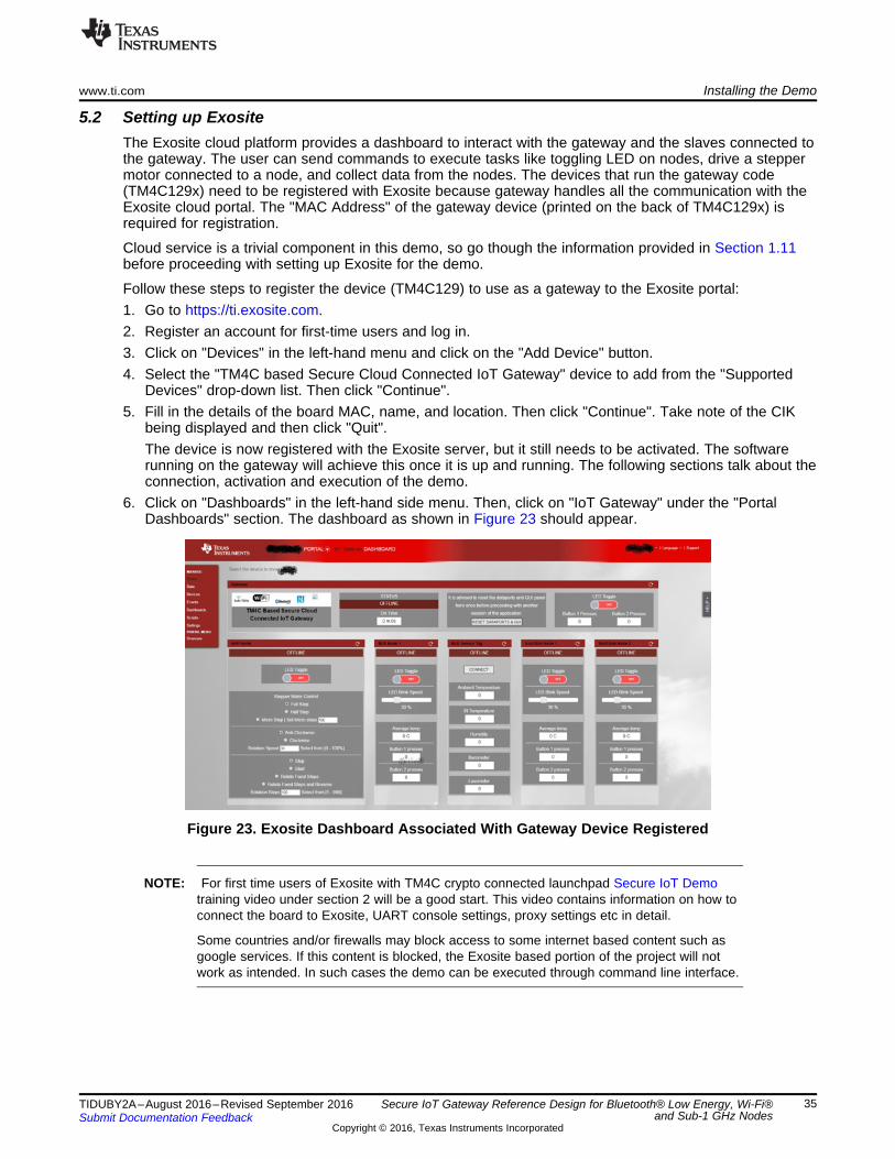
5.2 Setting up ExositeThe Exosite cloud platform provides a dashboard to interact with the gateway and the slaves connected tothe gateway. The user can send commands to execute tasks like toggling LED on nodes, drive a steppermotor connected to a node, and collect data from the nodes. The devices that run the gateway code(TM4C129x) need to be registered with Exosite because gateway handles all the communication with theExosite cloud portal. The "MAC Address" of the gateway device (printed on the back of TM4C129x) isrequired for registration.
Cloud service is a trivial component in this demo, so go though the information provided in Section 1.11before proceeding with setting up Exosite for the demo.
Follow these steps to register the device (TM4C129) to use as a gateway to the Exosite portal:1. Go to https://ti.exosite.com.2. Register an account for first-time users and log in.3. Click on "Devices" in the left-hand menu and click on the "Add Device" button.4. Select the "TM4C based Secure Cloud Connected IoT Gateway" device to add from the "Supported
Devices" drop-down list. Then click "Continue".5. Fill in the details of the board MAC, name, and location. Then click "Continue". Take note of the CIK
being displayed and then click "Quit".The device is now registered with the Exosite server, but it still needs to be activated. The softwarerunning on the gateway will achieve this once it is up and running. The following sections talk about theconnection, activation and execution of the demo.
6. Click on "Dashboards" in the left-hand side menu. Then, click on "IoT Gateway" under the "PortalDashboards" section. The dashboard as shown in Figure 23 should appear.
Figure 23. Exosite Dashboard Associated With Gateway Device Registered
NOTE: For first time users of Exosite with TM4C crypto connected launchpad Secure IoT Demotraining video under section 2 will be a good start. This video contains information on how toconnect the board to Exosite, UART console settings, proxy settings etc in detail.
Some countries and/or firewalls may block access to some internet based content such asgoogle services. If this content is blocked, the Exosite based portion of the project will notwork as intended. In such cases the demo can be executed through command line interface.

Demo Execution www.ti.com
36 TIDUBY2A–August 2016–Revised September 2016Submit Documentation Feedback
Copyright © 2016, Texas Instruments Incorporated
Secure IoT Gateway Reference Design for Bluetooth® Low Energy, Wi-Fi®and Sub-1 GHz Nodes
6 Demo ExecutionAll the individual subsystems of the demo must be set up and initialized before moving on to execute thedemo.
6.1 Connecting Gateway to Cloud Using Ethernet
1. Power off the TM4C129x CCLP.2. Connect the CC3100 Wi-Fi BoosterPack on the BoosterPack-2 interface on the TM4C129 CCLP. See
Section 2.2.1 to verify the header connections.3. Connect the EM Adapter BoosterPack to BoosterPack-1 Interface on TM4C129 CCLP. See
Section 2.2.1 to verify the header connections. Connect the CC2650 BLE Device to the EM AdapterBoosterPack.
4. Connect the TRF7970A NFC Boosterpack to the EM Adapter BoosterPack, which is already connectedto the TM4C129 CCLP in the previous step. See Section 2.2.1 verify the header connections.
Figure 24. Connecting All Hardware Components of the Gateway
5. Connect the EM Adapter BoosterPack to BoosterPack-2 Interface on TM4C129 CCLP over theCC3100 BoosterPack, which was connected in Step 2. See Section 2.2.1 to verify the headerconnections. Connect the CC1310 Sub-1GHz device to this EM Adapter BoosterPack. Also mount theantenna on the Sub-1GHz device.
6. Connect an Ethernet LAN cable to connect the gateway to a LAN port with working internetconnection.
7. Power on the board by connecting the TM4C129 CCLP to a power source using a USB cable to seethe LED2, LED3, and LED4 with all three flashing at regular intervals. LED1 should start flashing aftera few seconds once the gateway is connected to cloud. If LED1 does not flash or if the application isrun behind a proxy network, configure Proxy and NTP. See Section 6.7 for command line options.
8. Now go to the dashboard "IoT Gateway", which should display the gateway as "ONLINE" as shown inFigure 25 if connected properly.

www.ti.com Demo Execution
37TIDUBY2A–August 2016–Revised September 2016Submit Documentation Feedback
Copyright © 2016, Texas Instruments Incorporated
Secure IoT Gateway Reference Design for Bluetooth® Low Energy, Wi-Fi®and Sub-1 GHz Nodes
Figure 25. IoT Gateway Dashboard Showing Gateway ONLINE
6.2 Connecting Wi-Fi Node to Gateway
1. Make sure the TM4C123 LP is powered off before proceeding.2. Connect the TM4C123 LP and CC3100 Wi-Fi BoosterPack to the TM4C123 swizzle adapter board at
their designated BoosterPack interfaces. See Section 2.2.2 to verify header connections.3. Connect the RF430 NFC Tag BoosterPack to the TM4C123 swizzle adapter board at its designated
location (recommended as shown in Figure 26). See Section 2.2.2 to verify header connections.
Figure 26. Connecting all Hardware Components of the Wi-Fi Node

Swizzle board
Copyright © 2016, Texas Instruments Incorporated
TM4C123
CC3100RF430
DR
V8833
DRV8833
1
2
3
4
5
6
7
8
AIN1
AIN2
BIN2
BIN1
VDD
GND
AOUT1
AOUT2
BOUT1
BOUT2
Stepper motor
A
A
B
B
Demo Execution www.ti.com
38 TIDUBY2A–August 2016–Revised September 2016Submit Documentation Feedback
Copyright © 2016, Texas Instruments Incorporated
Secure IoT Gateway Reference Design for Bluetooth® Low Energy, Wi-Fi®and Sub-1 GHz Nodes
4. Now connect the DRV8833 stepper motor drive to the TM4C123 swizzle adapter board as shown inFigure 27. Connect the +ve and –ve terminals of the external power supply to the DRV883 board usingthe pins on the swizzle board. The DRV883 can also be powered from the 5-V pin in the TM4C123LaunchPad header as shown with the red lines in Figure 27, provided the USB power source cansupply up to 2 A. Also, refer to the stepper motor’s user guide to connect the correct terminals of thestepper motor (A, A, B, B) to their corresponding pins on DRV8833 board. See Section 2.2.2 to verifyheader connections.
Figure 27. Connecting Swizzle Board, Stepper Motor, and External Power Supply to theDRV8833 Driver Board
5. Supply power to the TM4C123 LP by connecting it to a power source using the USB cable. The whitecolor LED should flash once.
6. Tap the NFC tag on Wi-Fi node subsystem with the NFC transceiver on the gateway subsystem toexchange Wi-Fi credentials. The LED on the TM4C123x LP turns blue to indicate that connection tothe gateway is in progress. Once the node connects to the gateway, this LED will turn to green;otherwise, if the connection is not successful, the LED turns red. Tap again to retry.On the gateway side, the LED3 should get switched on (green color) to indicate that the Wi-Fi slave isconnected.

www.ti.com Demo Execution
39TIDUBY2A–August 2016–Revised September 2016Submit Documentation Feedback
Copyright © 2016, Texas Instruments Incorporated
Secure IoT Gateway Reference Design for Bluetooth® Low Energy, Wi-Fi®and Sub-1 GHz Nodes
6.3 Connecting BLE Node to Gateway
1. Make sure that the TM4C123x LP is switched off before proceeding.2. Connect the EM Adapter BoosterPack to the TM4C123x LP as shown in Figure 28.3. Connect the CC2650 to the header present on the EM Adapter BoosterPack as shown.4. Connect the RF430C330H NFC Tag to the EM Adapter BoosterPack as shown in Figure 28
(recommended).
Figure 28. Connecting All Hardware Components of the BLE Node
5. Supply power to the TM4C123 LP by connecting it to a PC using the USB cable. The green LEDshould now flash at regular intervals.
6. Tap the NFC tag on the BLE node subsystem with the NFC transceiver on the gateway subsystem toexchange credentials. The LED on TM4C123x LP turns from green to blue (and continues to blink atregular intervals) to indicate that connection has been established with the gateway.On the gateway side, the LED2 should turn on (green color) to indicate that the BLE slave isconnected.
6.4 Connecting SensorTag to GatewayConnect the SensorTag to the gateway with the Exosite GUI and IoT gateway dashboard by clicking onthe "Connect" button in the SensorTag widget. In a few seconds, the widget should show the SensorTagstatus as ONLINE. Before connecting to the gateway using Exosite GUI, the BLE SensorTag must be inadvertising mode.
To connect the SensorTag using command line, see Section 6.7.

Demo Execution www.ti.com
40 TIDUBY2A–August 2016–Revised September 2016Submit Documentation Feedback
Copyright © 2016, Texas Instruments Incorporated
Secure IoT Gateway Reference Design for Bluetooth® Low Energy, Wi-Fi®and Sub-1 GHz Nodes
6.5 Connecting Sub-1GHz Nodes to Gateway
1. Make sure that the TM4C123x LP is switched off before proceeding.2. Connect the EM Adapter BoosterPack to the TM4C123x, and then connect the CC1310 to the header
present on the EM Adapter BoosterPack as shown in Figure 29.3. Connect the RF430C330H NFC Tag to the EM Adapter BoosterPack as shown (recommended).
Figure 29. Connecting All Hardware Components of the Sub-1GHz Node
4. Supply power to the TM4C123 LP by connecting it to a power source using the USB cable. The greenLED should now flash at regular intervals.
5. Tap the NFC tag on the Sub-1GHz node subsystem with the NFC transceiver on the gatewaysubsystem to exchange credentials.
6. The LED on the TM4C123x LP turns from green to blue (and continues to blink at regular intervals) toindicate that the connection has been established with the gateway.
7. On the gateway side, the LED3 switches on permanently to indicate that the Sub-1GHz slave isconnected.
www.ti.com Demo Execution
41TIDUBY2A–August 2016–Revised September 2016Submit Documentation Feedback
Copyright © 2016, Texas Instruments Incorporated
Secure IoT Gateway Reference Design for Bluetooth® Low Energy, Wi-Fi®and Sub-1 GHz Nodes
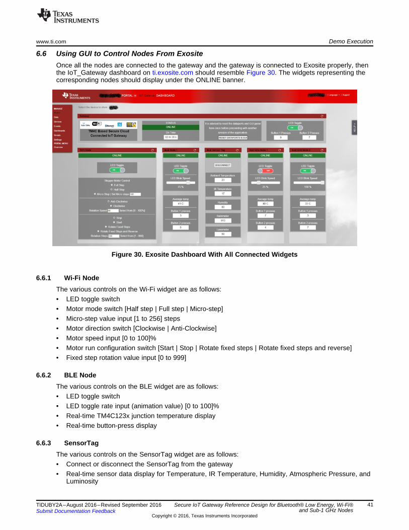
6.6 Using GUI to Control Nodes From ExositeOnce all the nodes are connected to the gateway and the gateway is connected to Exosite properly, thenthe IoT_Gateway dashboard on ti.exosite.com should resemble Figure 30. The widgets representing thecorresponding nodes should display under the ONLINE banner.
Figure 30. Exosite Dashboard With All Connected Widgets
6.6.1 Wi-Fi NodeThe various controls on the Wi-Fi widget are as follows:• LED toggle switch• Motor mode switch [Half step | Full step | Micro-step]• Micro-step value input [1 to 256] steps• Motor direction switch [Clockwise | Anti-Clockwise]• Motor speed input [0 to 100]%• Motor run configuration switch [Start | Stop | Rotate fixed steps | Rotate fixed steps and reverse]• Fixed step rotation value input [0 to 999]
6.6.2 BLE NodeThe various controls on the BLE widget are as follows:• LED toggle switch• LED toggle rate input (animation value) [0 to 100]%• Real-time TM4C123x junction temperature display• Real-time button-press display
6.6.3 SensorTagThe various controls on the SensorTag widget are as follows:• Connect or disconnect the SensorTag from the gateway• Real-time sensor data display for Temperature, IR Temperature, Humidity, Atmospheric Pressure, and
Luminosity

Demo Execution www.ti.com
42 TIDUBY2A–August 2016–Revised September 2016Submit Documentation Feedback
Copyright © 2016, Texas Instruments Incorporated
Secure IoT Gateway Reference Design for Bluetooth® Low Energy, Wi-Fi®and Sub-1 GHz Nodes
6.6.4 Sub-1GHz NodeThe various controls on the Sub-1GHz widget are as follows:• LED toggle switch• LED toggle rate input (animation value) [0 to 100]%• Real-time TM4C123x junction temperature display• Real-time button-press display
6.7 Command Line InterfaceThe gateway demonstration can be performed through command line interface featuring the command setlisted in Table 15.
To use the following commands, follow these steps:1. Power up the gateway by connecting it to a PC using USB cable.2. Open a console terminal using software like Tera Term or RealTerm or Putty with settings [Serial COM
Port Connection | Bitrate 115200].3. Press "Reset" on the gateway device to restart the gateway. The console will display some info as
shown in Figure 31.
Figure 31. Gateway Console Debug Output
4. Hit "Enter" to see a command prompt as shown in Figure 32. See Section 6.7.1 for a list of validcommands accepted by the gateway.
www.ti.com Demo Execution
43TIDUBY2A–August 2016–Revised September 2016Submit Documentation Feedback
Copyright © 2016, Texas Instruments Incorporated
Secure IoT Gateway Reference Design for Bluetooth® Low Energy, Wi-Fi®and Sub-1 GHz Nodes
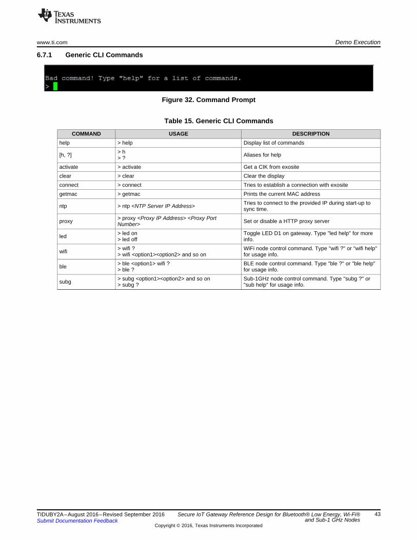
6.7.1 Generic CLI Commands
Figure 32. Command Prompt
Table 15. Generic CLI Commands
COMMAND USAGE DESCRIPTIONhelp > help Display list of commands
[h, ?] > h> ? Aliases for help
activate > activate Get a CIK from exositeclear > clear Clear the displayconnect > connect Tries to establish a connection with exositegetmac > getmac Prints the current MAC address
ntp > ntp <NTP Server IP Address> Tries to connect to the provided IP during start-up tosync time.
proxy > proxy <Proxy IP Address> <Proxy PortNumber> Set or disable a HTTP proxy server
led > led on> led off
Toggle LED D1 on gateway. Type "led help" for moreinfo.
wifi > wifi ?> wifi <option1><option2> and so on
WiFi node control command. Type "wifi ?" or "wifi help"for usage info.
ble > ble <option1> wifi ?> ble ?
BLE node control command. Type "ble ?" or "ble help"for usage info.
subg > subg <option1><option2> and so on> subg ?
Sub-1GHz node control command. Type "subg ?" or"sub help" for usage info.

Demo Execution www.ti.com
44 TIDUBY2A–August 2016–Revised September 2016Submit Documentation Feedback
Copyright © 2016, Texas Instruments Incorporated
Secure IoT Gateway Reference Design for Bluetooth® Low Energy, Wi-Fi®and Sub-1 GHz Nodes
6.7.2 Controlling Nodes Using CLI CommandsThe application demo can be executed locally in case the connection to the cloud is absent. Commands toachieve that are described in Table 16:
NOTE: Contents in the square brackets [ ] indicate the options available for the respectivecommands separated with a comma.
Table 16. Wi-Fi Node CLI Commands
COMMAND DESCRIPTIONwifi led [on, off] Toggle LED on BLE Nodewifi motor speed [0 to 100] Change the speed of motorwifi motor dir [clock, anti-clock] Change the direction of motorwifi motor mode [1 to 255] Change the motor mode [1: Full Step, 2: Half Step, [3 to 255]: Micro Step]wifi motor rfs [1 to 999] Run fixed number of steps [Min: 1, Max: 999]wifi motor rfr [1 to 999] Run fixed number of steps and then reverse [Min: 1, Max: 999]wifi motor run Run the motor freelywifi motor stop Stop the motor
Table 17. BLE Node CLI Commands
COMMAND DESCRIPTIONble sensor-tag connect Connect to SensorTag [SensorTag should be advertising]ble sensor-tag disconnect Disconnect form the SensorTagble sensor-tag status Get the current status of SensorTag datable node led [on, off] Toggle LED on BLE nodeble node animation [0 to 100] Change the rate of blinking of led on BLE nodeble node status Get the current status of Data coming from BLE node
Table 18. Sub-1GHz Node CLI Commands
COMMAND DESCRIPTIONsub [node1, node2] led [on, off] Toggle LED on one of the Sub-1GHz nodessub [node1, node2] animation [0 to100] Change the rate of blinking of led on one of the Sub-1GHz nodes
sub [node1, node2] status Get the current status of data coming from one of the Sub-1GHz nodes
www.ti.com Design Files
45TIDUBY2A–August 2016–Revised September 2016Submit Documentation Feedback
Copyright © 2016, Texas Instruments Incorporated
Secure IoT Gateway Reference Design for Bluetooth® Low Energy, Wi-Fi®and Sub-1 GHz Nodes
7 Design Files
7.1 SchematicsTo download the schematics, see the design files at TIDM-TM4C129XGATEWAY.
7.2 Bill of MaterialsTo download the bill of materials (BOM), see the design files at TIDM-TM4C129XGATEWAY.
7.3 PCB Layout RecommendationsAny additional note you think the customer would need to layout this board; also add details on thereasoning behind your layout (form factor, heat distribution, and so on.)
7.3.1 Layout PrintsTo download the layer plots, see the design files at TIDM-TM4C129XGATEWAY.
7.4 Altium ProjectTo download the Altium project files, see the design files at TIDM-TM4C129XGATEWAY.
7.5 Gerber FilesTo download the Gerber files, see the design files at TIDM-TM4C129XGATEWAY.
7.6 Assembly DrawingsTo download the assembly drawings, see the design files at TIDM-TM4C129XGATEWAY.
8 Software FilesTo download the software files, see the design files at TIDM-TM4C129XGATEWAY.

References www.ti.com
46 TIDUBY2A–August 2016–Revised September 2016Submit Documentation Feedback
Copyright © 2016, Texas Instruments Incorporated
Secure IoT Gateway Reference Design for Bluetooth® Low Energy, Wi-Fi®and Sub-1 GHz Nodes
9 References
1. Texas Instruments, Tiva™ TM4C123GH6PM Microcontroller, Datasheet (SPMS376)2. Texas Instruments, DRV8833 Dual H-Bridge Motor Driver, DRV8833 Datasheet (SLVSAR1)3. Texas Instruments, CC3100 SimpleLink™ Wi-Fi® and IoT Solution Getting Started Guide, User's
Guide (SWRU375)4. Texas Instruments, ARM® Cortex®-M4F Based MCU TM4C123G LaunchPad™ Evaluation Kit, EK-
TM4C123GXL Product Page (http://www.ti.com/tool/EK-TM4C123GXL)5. Texas Instruments, DRV8833 Evaluation Module User's Guide (SLVU498)6. Texas Instruments, SimpleLink™ Wi-Fi® CC3100 wireless network processor BoosterPack™ plug-in
module (http://www.ti.com/tool/cc3100boost)7. Texas Instruments, TivaWare™ Sensor Library, User's Guide (SPMU371)8. Texas Instruments, SimpleLink Wi-Fi CC3100 SDK (http://www.ti.com/tool/cc3100sdk)9. Texas Instruments, Stellaris® In-Circuit Debug Interface (ICDI) and Virtual COM Port Driver Installation
Instructions, Quick Start Guide (SPMU287)10. Texas Instruments, CC31xx & CC32xx UniFlash Quick Start Guide, TI Wiki
(http://processors.wiki.ti.com/index.php/CC31xx_%26_CC32xx_UniFlash_Quick_Start_Guide)11. Texas Instruments, High Resolution Microstepping Driver With the DRV88xx Series, Application
Report (SLVA416)12. Texas Instruments, TM4C1294x Wi-Fi Enabled IoT Node, TIDM-TM4C129XWIFI Design Guide
(TIDU992)
10 About the AuthorSUDHAKAR SINGH is a software engineer in the Performance Microcontroller group at TexasInstruments, where he primarily works on TM4C software development, customer support, and referencedesign development. Sudhakar received his bachelor of engineering in computer science and engineeringfrom the PEC University of Technology, India.

www.ti.com Revision A History
47TIDUBY2A–August 2016–Revised September 2016Submit Documentation Feedback
Copyright © 2016, Texas Instruments Incorporated
Revision History
Revision A HistoryNOTE: Page numbers for previous revisions may differ from page numbers in the current version.
Changes from Original (August 2016) to A Revision ..................................................................................................... Page
• Changed title from TM4C Based Secure Cloud Connected IoT Gateway for BLE, Wi-Fi, and Sub-1GHz Nodes ........... 1

IMPORTANT NOTICE FOR TI REFERENCE DESIGNS
Texas Instruments Incorporated (‘TI”) reference designs are solely intended to assist designers (“Designer(s)”) who are developing systemsthat incorporate TI products. TI has not conducted any testing other than that specifically described in the published documentation for aparticular reference design.TI’s provision of reference designs and any other technical, applications or design advice, quality characterization, reliability data or otherinformation or services does not expand or otherwise alter TI’s applicable published warranties or warranty disclaimers for TI products, andno additional obligations or liabilities arise from TI providing such reference designs or other items.TI reserves the right to make corrections, enhancements, improvements and other changes to its reference designs and other items.Designer understands and agrees that Designer remains responsible for using its independent analysis, evaluation and judgment indesigning Designer’s systems and products, and has full and exclusive responsibility to assure the safety of its products and compliance ofits products (and of all TI products used in or for such Designer’s products) with all applicable regulations, laws and other applicablerequirements. Designer represents that, with respect to its applications, it has all the necessary expertise to create and implementsafeguards that (1) anticipate dangerous consequences of failures, (2) monitor failures and their consequences, and (3) lessen thelikelihood of failures that might cause harm and take appropriate actions. Designer agrees that prior to using or distributing any systemsthat include TI products, Designer will thoroughly test such systems and the functionality of such TI products as used in such systems.Designer may not use any TI products in life-critical medical equipment unless authorized officers of the parties have executed a specialcontract specifically governing such use. Life-critical medical equipment is medical equipment where failure of such equipment would causeserious bodily injury or death (e.g., life support, pacemakers, defibrillators, heart pumps, neurostimulators, and implantables). Suchequipment includes, without limitation, all medical devices identified by the U.S. Food and Drug Administration as Class III devices andequivalent classifications outside the U.S.Designers are authorized to use, copy and modify any individual TI reference design only in connection with the development of endproducts that include the TI product(s) identified in that reference design. HOWEVER, NO OTHER LICENSE, EXPRESS OR IMPLIED, BYESTOPPEL OR OTHERWISE TO ANY OTHER TI INTELLECTUAL PROPERTY RIGHT, AND NO LICENSE TO ANY TECHNOLOGY ORINTELLECTUAL PROPERTY RIGHT OF TI OR ANY THIRD PARTY IS GRANTED HEREIN, including but not limited to any patent right,copyright, mask work right, or other intellectual property right relating to any combination, machine, or process in which TI products orservices are used. Information published by TI regarding third-party products or services does not constitute a license to use such productsor services, or a warranty or endorsement thereof. Use of the reference design or other items described above may require a license from athird party under the patents or other intellectual property of the third party, or a license from TI under the patents or other intellectualproperty of TI.TI REFERENCE DESIGNS AND OTHER ITEMS DESCRIBED ABOVE ARE PROVIDED “AS IS” AND WITH ALL FAULTS. TI DISCLAIMSALL OTHER WARRANTIES OR REPRESENTATIONS, EXPRESS OR IMPLIED, REGARDING THE REFERENCE DESIGNS OR USE OFTHE REFERENCE DESIGNS, INCLUDING BUT NOT LIMITED TO ACCURACY OR COMPLETENESS, TITLE, ANY EPIDEMIC FAILUREWARRANTY AND ANY IMPLIED WARRANTIES OF MERCHANTABILITY, FITNESS FOR A PARTICULAR PURPOSE, AND NON-INFRINGEMENT OF ANY THIRD PARTY INTELLECTUAL PROPERTY RIGHTS.TI SHALL NOT BE LIABLE FOR AND SHALL NOT DEFEND OR INDEMNIFY DESIGNERS AGAINST ANY CLAIM, INCLUDING BUT NOTLIMITED TO ANY INFRINGEMENT CLAIM THAT RELATES TO OR IS BASED ON ANY COMBINATION OF PRODUCTS ASDESCRIBED IN A TI REFERENCE DESIGN OR OTHERWISE. IN NO EVENT SHALL TI BE LIABLE FOR ANY ACTUAL, DIRECT,SPECIAL, COLLATERAL, INDIRECT, PUNITIVE, INCIDENTAL, CONSEQUENTIAL OR EXEMPLARY DAMAGES IN CONNECTION WITHOR ARISING OUT OF THE REFERENCE DESIGNS OR USE OF THE REFERENCE DESIGNS, AND REGARDLESS OF WHETHER TIHAS BEEN ADVISED OF THE POSSIBILITY OF SUCH DAMAGES.TI’s standard terms of sale for semiconductor products (http://www.ti.com/sc/docs/stdterms.htm) apply to the sale of packaged integratedcircuit products. Additional terms may apply to the use or sale of other types of TI products and services.Designer will fully indemnify TI and its representatives against any damages, costs, losses, and/or liabilities arising out of Designer’s non-compliance with the terms and provisions of this Notice.IMPORTANT NOTICE
Mailing Address: Texas Instruments, Post Office Box 655303, Dallas, Texas 75265Copyright © 2016, Texas Instruments Incorporated