securing rds broadcast messages for smart grid...
TRANSCRIPT

Securing RDS Broadcast Messages for Smart Grid
Applications
Monageng Kgwadi and Thomas Kunz
Technical Report SCE-09-06
Department of Systems and Computer Engineering
Carleton University
Ottawa, Canada
April 2009
Carleton University, Technical Report SCE-09-06, April 2009
Abstract
Efforts to reduce peak electrical demand has led to the introduction of demand responseprograms for residences. Demand response programs allow customers to reduce or shifttheir electrical consumption from peak periods in response to dynamic prices of electricity.Utility companies broadcasts the prices to the customers who then respond by reducingconsumption during peak periods or shift the consumption to off-peak periods. Similarly,direct load control programs entice consumers with special rates or other incentives forallowing the utility to control load (typically air conditioning) for a number of days peryear. Both uses require a ubiqituous and cost-effective communication network to allowutilities to communicate with users and appliances. The Radio Data System (RDS) hasbeen identified as one strong candidate technology. However, security concerns arise dueto the wireless nature of the communication channel. Source authentication is crucial indemand response to ensure that only authenticated messages are responded to.
This report presents evaluations of cryptographic methods that could be employed tooffer source authentication over the RDS network. Simulations are used to determine theimpact on the network performance by employing digital signatures to allow source au-thentication. The simulations were calibrated with data collected in Ottawa, Canada, inparticular to model signal propagation characteristics. While different environments ex-perience different path losses, the relative comparisons are not impacted by this difference,however. The authentication schemes studied all provide strong authentication againstattackers who attempt to forge signatures without knowledge of private keys (which areheld at the transmitter). The information exposed in the transmitted messages will nothelp an attacker in forging future messages. And as messages are time-sensitive andthe senders and receivers in the network coarsely time-synchronized, replay-attacks areprevented as well. This is different from shared-key/secret-key schemes such as the oneemployed in Zigbee, where exposure of the secret key on the receiver side (using bit sniff-ing or other techniques to access the non-volatile memory on the receiver) compromisesthe security/authentication of messages.
The report presents comparisons of the security offered by the protocols, the band-width overhead, computational costs and message reception probability. Our simulationresults show that, up to a distance of 90 km, all authentication schemes do not affectmessage reception by the receivers. Beyond that, all the schemes have an effect on mes-sage reception due to increased message sizes and receiver bootstrapping for BiBa andHORSE. ECDSA and HORSE outperform BiBa in terms of message reception beyond 90km and the difference between the two is not significant. ECDSA however offers highersecurity than HORSE and BiBa but at the cost of increased computational complexity,in particular at the receivers. In addition, ECDSA has the highest bandwidth overhead.
i

Carleton University, Technical Report SCE-09-06, April 2009
Contents
1 Introduction 1
2 Background 3
3 Threat Model 5
4 Literature Survey on Possible Mitigation Steps 74.1 Secure SCADA using DNP3 . . . . . . . . . . . . . . . . . . . . . . . . . . 74.2 Authentication using RF fingerprints . . . . . . . . . . . . . . . . . . . . . 94.3 Zero-knowledge device authentication . . . . . . . . . . . . . . . . . . . . . 104.4 The TESLA Broadcast Authentication Protocol . . . . . . . . . . . . . . . 11
5 Cryptographical Security Measures 145.1 BiBa Signature Protocol . . . . . . . . . . . . . . . . . . . . . . . . . . . . 14
5.1.1 Authenticating PCT Messages using BiBa . . . . . . . . . . . . . . 165.1.2 Protocol Messages . . . . . . . . . . . . . . . . . . . . . . . . . . . 185.1.3 Setting the BiBa Parameters . . . . . . . . . . . . . . . . . . . . . . 19
5.2 HORSE Authentication Protocol . . . . . . . . . . . . . . . . . . . . . . . 205.2.1 Authenticating PCT Messages using HORSE . . . . . . . . . . . . . 225.2.2 HORSE Protocol Messages . . . . . . . . . . . . . . . . . . . . . . 22
5.3 The Elliptic Curve Digital Signature Algorithm . . . . . . . . . . . . . . . 255.3.1 Authenticating PCT Messages using ECDSA . . . . . . . . . . . . . 26
6 Simulation Results and Analysis 276.1 BiBa Performance Results . . . . . . . . . . . . . . . . . . . . . . . . . . . 286.2 HORSE Performance Results . . . . . . . . . . . . . . . . . . . . . . . . . 316.3 ECDSA Performance Results . . . . . . . . . . . . . . . . . . . . . . . . . 336.4 Comparing the Authentication Protocols . . . . . . . . . . . . . . . . . . . 33
7 Conclusions 37
ii

Carleton University, Technical Report SCE-09-06, April 2009
1 Introduction
The need to reduce peak electrical demand has resulted in plans to introduce demandresponse programs for residences. Demand response programs allow customers to adjusttheir electrical consumption in response to dynamic prices of electricity. In such programs,the utility company informs the customers of a price event to which the customers chooseto respond. Price events alert customers of a change in the prices of electricity. Customerswould then minimize their consumption during periods with high prices, resulting in lowerpower bills. Emergency events deal with issues concerning grid reliabilities. In the eventof a grid instability, the utility company issues emergency events which compel customersto lower their consumption, thus reducing the load and alleviating the strained grid. Theuse of demand response provides utility companies with another option to perform loadmanagement in addition to load shedding and power purchase. Demand response usesboth the price events and emergency events to improve reliability and lower electricitycosts to customers.
The Programmable Communicating Thermostat (PCT) system is aimed at reducingelectrical power consumption during peak demand periods. The PCT system allows de-mand response programs to be applied on the power consumed by air conditioning ofresidences. The system allows thermostats to receive pricing events broadcast over awireless communication channel from the utility companies. The programmable ther-mostats operate in an automated manner. A customer programs the thermostat and thethermostat responds to event messages accordingly. The operation of the thermostats,and consequently demand response programs over the PCT system, rely on successfuldelivery of valid event messages. Therefore, there is a need to ensure the integrity of themessages and authenticate their origin.
In addition to the above use of messages to enable users to respond to dynamic energyprices in residences, direct load control that does not use dynamic energy prices. Instead,consumers are provided special rates or other incentives for allowing the utility to controlload (typically air conditioning) for a number of days per year. Also, the original PCTsystem concept has since been expanded to include a range of Programmable Communi-cating Devices (PCDs), including PCTs, in-home displays, smart appliances and controlswitches for air conditioning, water heaters and other high energy consuming devices. Infuture extensions, plug-in hybrid vehicles could also be included. However, in all theseextensions of the original idea, the overall concept is the same: utilities send messages todevices to inform users and to potentially directly control the load. Therefore, the sameneed for reliable message delivery, message integrity, and proper authentication arises. Inthe remainder of this report, we will use the PCT system as the example PCD system,as this work was started with respect to the requirements identified for the PCT system.But the key insights and solutions apply equally well to a more general definition of areceiver device, be it a thermostat, in-home displays, or smart appliances.
The draft reference design for PCTs mandates a nation-wide wireless broadcast com-munications network using either the Radio Broadcast Data Network (RBDS or RDS) orthe Paging system [1]. Later revisions identified the RDS as the communications infras-tructure to be employed for the PCT system. The wireless nature of the communicationinfrastructure puts the smart grid applications running over it at a security risk. The
1

Carleton University, Technical Report SCE-09-06, April 2009
RDS network does not employ any security mechanisms on which the PCT or a PCDsystem can rely. Therefore there is need to provide for secure means of communicatingPCD system messages over the RDS network. This report proposes solutions to addressthe security over the RDS network. The solutions presented in this report can be em-ployed to authenticate messages sent by any application using the RDS network as thephysical infrastructure. A PCD or PCT system is an immediate beneficiary to the ser-vice, hence it is presented as a test case. In [2], the possible security threats to the PCTsystem are studied and a risk management approach is used to propose mitigation stepsfor the security concerns. This report provides an analysis of the security threats fora communication protocol for use with PCTs. A literature survey of security issues insimilar networks is carried out to identify solutions that could be used or extended tothe PCT system. Of particular interest are sensor networks and RFID networks becausethey face similar challenges of limited resources. The report also identifies possible solu-tions that could be pursued to provide authentication over the RDS network and theirimpact on the network. Three authentication schemes identified to be suitable for theRDS network,(BiBa, HORSE, ECDSA) are investigated using simulations to determinethe impact on network resources.
A background on the security of the PCT system, RDS network and security implica-tions is given in Section 2. The threat model as relevant to the PCT system employing theRDS network for communication is presented in Section 3. A literature survey of securityschemes available is presented in Section 4. Section 5 gives detailed description of threeauthentication schemes suitable for the RDS network and how they can be employed toauthenticate messages. Analysis of simulation results of the three authentication protocolsis then presented in Section 6. A conclusion is then presented in section 7.
2
Carleton University, Technical Report SCE-09-06, April 2009
2 Background
An initial study of the security characteristics of the PCT system in [2] advocatesa tiered security solution. The solution defines the System Owner as responsible foroverseeing and controlling the PCT system. All the messages that the System Ownersends to the PCTs go through the System Operator. The System Operator is responsiblefor delivering the messages to the PCTs within its geographical or logical coverage area.The goal of our study is to provide secure communication between the System Operatorand the PCTs using the Radio Broadcast Data System (RBDS or RDS) network.
The Radio Data System (RDS) was designed to carry small packets on the FM channelin the range of 87.5MHz to 108.0MHz. It has been used to convey program informa-tion and traffic information to radios in vehicles [3]. The Radio Broadcast Data System(RBDS) is the North American equivalent of the Radio Data System (RDS) which is aEuropean standard. In this document the terms RBDS and RDS are used interchange-ably. RDS is a broadcast one-way communication channel and has no security featuresthat the PCT system can rely upon. This leaves it to the application using the RDSnetwork to do the required security and authentication. This means that messages thatrequire security need to be encrypted to ensure security. In the PCT system, privacyis not as much a priority as authentication. The event messages are to be broadcast toalert everybody about events, therefore there is no need to make such messages secret.Authentication however is necessary to ensure that only authenticated messages are re-sponded to. As pointed out in [2], an attacker could cancel events prior to their intendedperiod elapses. The attacker in this and many other ways can cause distress and possi-bly cause grid instabilities, effectively defeating the whole purpose of demand response.Therefore, the PCTs have to authenticate the origin of the message and only respond toan authenticated sender(s).
There is need to provide for security in the design of the communication protocol asrecommended by [2]. The security of such a system should be resilient to attacks andbe able to recover easily from a breach. Bono et al show in [4] that obscurity is not agood measure for ensuring security. They advocate the use of standard cryptographicalgorithms employing keys of sufficient lengths. They demonstrate this by bypassing theimmobilizer of a vehicle which employs a cryptographically-enabled RFID tag. Theyachieved this by reverse engineering, key-cracking and simulation. The immobilizer intheir study employed a Texas Instrument Digital Signature Transponder (DST). Fromthe knowledge of a rough schematic posted on the Internet, they were able to determinethe functional details of the cipher of the DST. The challenge/response authenticationmessages between the reader and the tag were obtained and used to crack the key. The40-bit shared secret key was extracted with the use of an array of FPGAs in less than anhour. Then, using the extracted key, they were able to simulate the RF output to spoofthe reader. In their study, they were able to establish conditions for hot-wiring a car withfairly modest resources.
Strong cryptographic algorithms add to the complexity and ultimately the cost of man-ufacturing the devices. The price of the PCTs has to be minimized as they are expectedto retail at less than $50 [2]. Sensor networks and RFID networks face similar problemswith the need to provide security and still keeping the cost of the devices relatively low.
3

Carleton University, Technical Report SCE-09-06, April 2009
It could be expected that the PCTs may have slightly more computing resources, storage,and power supply than RFID tags and sensor nodes. However, the PCTs are still ex-pected to have modest computing and storage resources compared to today’s computers.This limitation means that the security and authentication algorithms employed on thesedevices be efficient and low cost.
Authentication poses more of a challenge in a one-way communication channel becauseconventional authentication methods of challenge/response cannot be used. In a chal-lenge/response authentication, a sender proves its identity to the receiver by respondingto a challenge from the receiver and vice versa. This cannot be done over the RBDSnetwork, since the PCTs do not have a communication channel to the System Operatorwith which they can challenge the identity. Even if such a channel existed, the volume ofchallenges coming from the PCTs would be too high to make this approach attractive.
4
Carleton University, Technical Report SCE-09-06, April 2009
3 Threat Model
The characteristics of an adversary and the impact of the threat posed need to be estab-lished before discussing mitigation strategies. The PCT system is subject to a number ofattacks as stated in [2]. The adversary that we discuss in our study is limited to one whoattacks the PCT system via the wireless communication channel. The motives of suchattackers could be anything from leisurely mischief to a terror attack targeting denial ofutility services to customers. According to [2], the attacks that an adversary could launchon the PCT system include, but is not limited to, the following :
• An attacker could cause unanticipated loads on the grid causing instabilities bysending false messages to customers. This could be done by canceling valid emer-gency event messages aimed at alleviating existing grid instabilities thus preventingthe expected reduction in load.
• An attacker could send false time synchronization messages creating erroneous be-havior of the PCTs.
• Customers could be deceived by false messages displayed by the PCTs if an attackercan successfully send such messages to the PCTs.
• A successful breach of the communication can allow an attacker to shut down PCTsor even install new software into the devices. An attacker who is able to shut downPCTs remotely could cause irritation, discomfort and health problem to some users.The installation of new software (potentially malicious) by an attacker may lead toerroneous operation of the PCTs.
• An attacker could jam the signal to a subset of receivers from a ground station oraircraft e.g. balloon.
A systematic risk analysis of the threat posed to the PCT system and counter measureswere fully described in [2]. For the purpose of this report we address the threat andmitigation procedure for a PCT system employing the RDS network to communicatemessages.
The nature of the RDS network limits the way an attacker can launch attacks. Thelack of a reverse communication channel from the PCTs to the System Operator meansthat the attacker should have physical access to a PCT to access information on it. Weassume that an attacker has unlimited access to PCTs, either from his/her own homeor he/she could break into someones home and access a networked PCT. Moreover, anattacker could easily purchase the device at a retail store. This means that the data storedon these devices can be retrieved by a determined attacker using any method at his/herdisposal. This setting does not bode well for security by obscurity of cryptographic keys.We assume it would be fairly easy for an attacker to retrieve a decryption key(s) fromthe PCT, thus the use of symmetric key cryptography should be avoided. Asymmetriccryptographic methods are more favorable for this setting. If public-key cryptography isused, an attacker would only retrieve public keys of the System Operator by attackingthe PCTs. An attacker would be forced to attack the Systems Operator to obtain theprivate keys that would allow him/her to encrypt messages.
5

Carleton University, Technical Report SCE-09-06, April 2009
Although the attacks on the PCTs are easy, as mentioned above, attacks on the sender(System Operator) are not trivial. An attacker wishing to get information from thesender is limited to eavesdropping or gaining direct (or indirect) access to the systeminformation database. The former method of attack means that the attacker is limited towhat is communicated and what is stored on the PCTs. Methods of communication thatreveal no information to an eavesdropper and store no critical information at the receivershould be employed to lower the risks of this type of attack. Gaining physical access tothe system database is not easy but none-the-less possible. An adversary could break intothe premises and obtain critical cryptographic information that would allow him/her tolaunch an attack. The critical information used for communication could also be leakedout through employees to an adversary by negligence, blackmail, extortion or ignorance,to mention a few. A decentralized method of storing cryptographical information shouldbe used to avoid a single point of compromise. To protect the cryptographical information,[2] suggests that complementary pieces of cryptographic information should not be storedin one place or exposed to one person.
Operation on the FM radio spectrum requires licensing from the radio spectrum man-agement organization. An attacker operating unlawfully on a frequency without a licensewould be stopped if detected. As part of their non-cryptographic solution to providesecurity, [2] proposes the use of monitors placed to detect infringements. The monitoringdevices should be conveniently placed to receive the messages and compare them withthose sent by the System Operator. These devices, carefully placed in the coverage area,will reflect what the PCTs receive from the network. With such measures in place, itwould be easy to detect if the messages are tempered with or if there are new unac-counted messages showing up at the PCTs. The authorities then would be alerted ofthe infringement. The use of a detection system cannot be relied upon to provide secu-rity. The attacks on the PCTs can go unnoticed if they are targeted to a small subsetof customers who are in the blindspot of the monitors. Moreover, the attacker could bemobile and operate for a short period and leave no trace. In such cases it would be verydifficult for authorities to stop future attacks by the same attacker even if such attacksare detected.
6
Carleton University, Technical Report SCE-09-06, April 2009
4 Literature Survey on Possible Mitigation Steps
Several symmetric and asymmetric cryptographic methods exist in the literature. Asurvey that covers the technical problems faced by RFID security and privacy is presentedin [5]. Several cryptographic methods are proposed in the literature for RFID tags in[6] and [7]. The methods of cryptography favored by the security experts consulted in[2] is the use of Elliptic Curve Cryptography (ECC). The following methods have beenidentified as promising to the application for electrical demand response in residentialdevices. The cryptographical authentication methods presented here were designed fornetworks different to the RBDS network. However, these could be extended or customizedto use on the RBDS network to offer the required security.
4.1 Secure SCADA using DNP3
Related developments in the power industry have been carried out to provide securecommunications for metering and Supervisory Control and Data Acquisition (SCADA)services over the existing power-line infrastructure [8]. The Real-Time Energy Manage-ment via Power-line and Internet (REMPLI) system was designed to permit remote andautonomous control and monitoring of energy resources by utility companies at residences[8]. The design requirements for the system were to allow various utility companies (e.g.electricity and gas) to offer their services to customers over a shared distribution network.The services required for support by REMPLI include load balancing, theft detection,remote monitoring and control.
Mander et al in [9] discuss a distributed security architecture using the Distributed Net-work Protocol (DNP3) to offer security for residential load-management devices. Theirsolution protects Intelligent Electronic Devices (IEDs) networked to a SCADA networkfrom cyber attacks. The DNP3 protocol is used widely in the world for electricity andwater utilities for communications with field equipment [10]. DNP3 does not provide suf-ficient security features, hence their solution extends DNP3 by adding a security layer andusing data object security [9]. The security extension to DNP3 provides authentication atthe data-link layer by using encryption. The security provides privacy to customers andconceals the events that IEDs are experiencing, which an attacker can exploit to attackand disrupt the system. Moreover, encryption prevent burglars from determining, basedon the energy consumption, if a house is occupied.
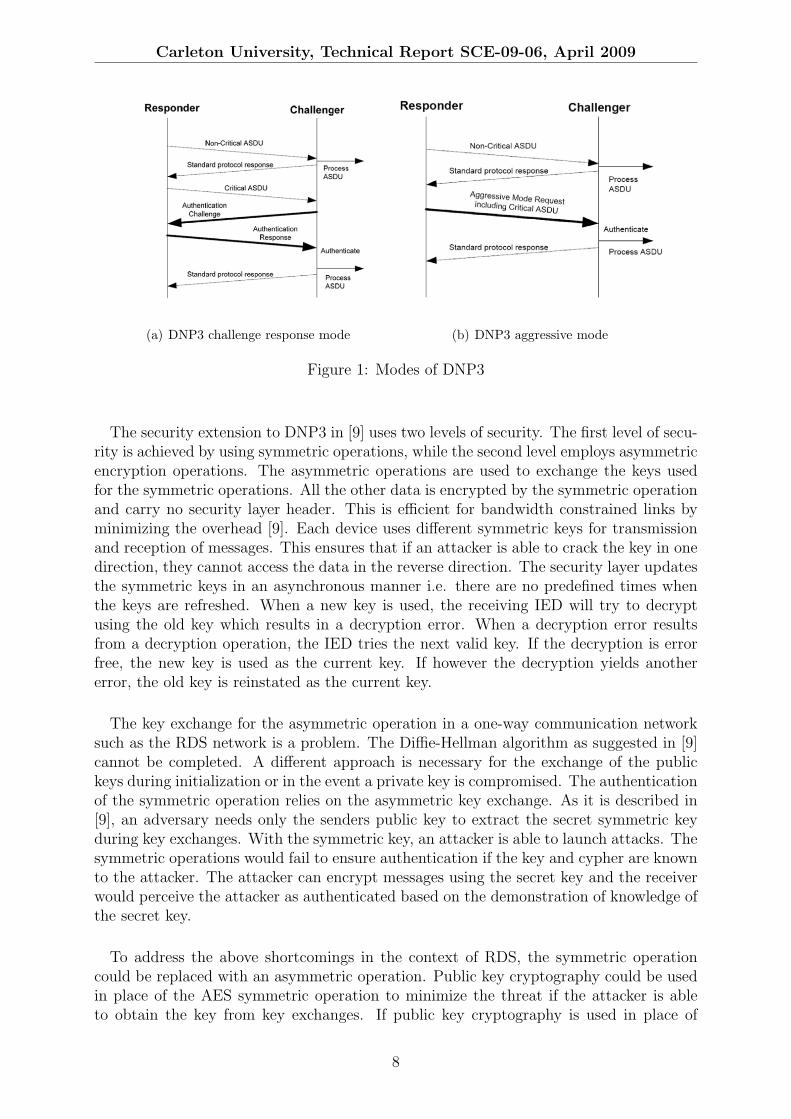
Figures 1(a) and 1(b) show how NDP3 is used for authenticating application messagesbetween two entities. DNP3 employs the challenge/response authentication method toauthenticate critical commands as shown in Figure 1(a). The receiver queries the iden-tity of the sender upon receiving a critical command. The sender proves its identityby demonstration of knowledge of shared cryptographic keys. The aggressive mode asshown in Figure 1(b) is used to conserve bandwidth by eliminating the challenge andresponse messages. In the aggressive mode, the authentication data is included in themessage. The aggressive mode is considered slightly less secure than the normal chal-lenge/response mode [10]. For the aggressive mode to be used there has to be at least onerequest/response authentication preceding it to establish trust between communicatingentities.
7
Carleton University, Technical Report SCE-09-06, April 2009
(a) DNP3 challenge response mode (b) DNP3 aggressive mode
Figure 1: Modes of DNP3
The security extension to DNP3 in [9] uses two levels of security. The first level of secu-rity is achieved by using symmetric operations, while the second level employs asymmetricencryption operations. The asymmetric operations are used to exchange the keys usedfor the symmetric operations. All the other data is encrypted by the symmetric operationand carry no security layer header. This is efficient for bandwidth constrained links byminimizing the overhead [9]. Each device uses different symmetric keys for transmissionand reception of messages. This ensures that if an attacker is able to crack the key in onedirection, they cannot access the data in the reverse direction. The security layer updatesthe symmetric keys in an asynchronous manner i.e. there are no predefined times whenthe keys are refreshed. When a new key is used, the receiving IED will try to decryptusing the old key which results in a decryption error. When a decryption error resultsfrom a decryption operation, the IED tries the next valid key. If the decryption is errorfree, the new key is used as the current key. If however the decryption yields anothererror, the old key is reinstated as the current key.
The key exchange for the asymmetric operation in a one-way communication networksuch as the RDS network is a problem. The Diffie-Hellman algorithm as suggested in [9]cannot be completed. A different approach is necessary for the exchange of the publickeys during initialization or in the event a private key is compromised. The authenticationof the symmetric operation relies on the asymmetric key exchange. As it is described in[9], an adversary needs only the senders public key to extract the secret symmetric keyduring key exchanges. With the symmetric key, an attacker is able to launch attacks. Thesymmetric operations would fail to ensure authentication if the key and cypher are knownto the attacker. The attacker can encrypt messages using the secret key and the receiverwould perceive the attacker as authenticated based on the demonstration of knowledge ofthe secret key.
To address the above shortcomings in the context of RDS, the symmetric operationcould be replaced with an asymmetric operation. Public key cryptography could be usedin place of the AES symmetric operation to minimize the threat if the attacker is ableto obtain the key from key exchanges. If public key cryptography is used in place of
8

Carleton University, Technical Report SCE-09-06, April 2009
the symmetric operation, the key exchange would involve only the public key. Even ifthe attacker is able to obtain the public key, he/she cannot authenticate him/herself tothe receiving device without knowledge of the private key. The key distribution issuestill persists with this approach. The initial set up of the session keys with which themessage keys are encrypted needs to be made seamless and easy to update in the case ofa compromised private key.
4.2 Authentication using RF fingerprints
The physical layer RF fingerprints can be used together with higher layer protocolmethods to provide authentication [11]. RF fingerprints identify an RF transmitter fromthe properties of the received radio signals. They allow different transmitters to be distin-guishable from one another. The authentication presented in [11] is for single-hop wirelesssensor networks. The application forms a network with authenticated hardware insteadof the users authenticating themselves. The nodes in the network have fingerprinting ca-pabilities and are able to distinguish RF sources without knowing their fingerprints beforeinitialization. On initialization, the nodes perform a neighbor discovery protocol and forma secure group of fully connected neighbors. The group members exchange the fingerprintinformation and then build credentials for group members. The credentials of group mem-bers are made up of RF fingerprints, RF identities and cryptographic identities. In thisway the network nodes authenticate their neighbors.
In the RDS network, a distributed approach as described in [11] is infeasible. However,the devices could be enabled to do RF fingerprinting and use location in the credentialsof the sender (System Operator). In this way an attacker masquerading as the SystemOperator would be forced to operate very close to the legitimate System Operator. If anattacker is forced to operate near the legitimate System Operator, then his/her effectiveradiated power would have to be comparable to the System Operator for his/her signalto be detectable. The total effective radiated power for systems operating in the RDSnetwork are in the order of tens of kilowatts. The cost of equipment and operation shouldserve as a deterrent for most attackers. Even if the attacker was able to obtain the equip-ment and broadcast messages, the spectrum management regulation body monitoring theuse of the radio spectrum could be relied upon stop the unlawful operation.
The use of RF fingerprints alone does not provide absolute security and has to be usedwith other cryptographic methods [11]. In the implementation described in [11], encryp-tion keys and RF credential should be used to provide security. For authentication onthe RDS network, the RF fingerprints are sufficient to identify the authentic sender fromattackers. The PCTs should be able to learn the new fingerprints of the System Opera-tor if the transmission RF equipment changes for any reason. The PCTs should be ableto distinguish an attacker from a legitimate System Operator with changed fingerprints.Additional hardware and digital signal processing (DSP) units would have to be incorpo-rated into the PCTs to enable RF fingerprinting. The extra hardware could potentiallydrive the cost of the PCTs high. The cost of such additional hardware is unknown to theauthor and requires investigation to determine if the solution is cost effective.
9

Carleton University, Technical Report SCE-09-06, April 2009
4.3 Zero-knowledge device authentication
A method that allows pre-authenticated response between RFID tags and readers waspresented in [12]. The solution curbs divulging critical information by RFID tags to anyrandom tags upon interrogation. Engberg et al in [12] propose a solution where tags onlyrespond to authenticated readers . The method was developed to avoid customer trackingusing RFID tags that the customer may have on them. The method employs the use ofa ’zero-knowledge’ device authentication method. The method is not technically conven-tional zero-knowledge, the authors claim zero-knowledge because the tags do not containany sensitive data. The tags relay the requests to the user/customer upon authenticatinga reader to which the customer responds.
The solution differs from the extension to DNP3 in that it does not use a chal-lenge/response method to authenticate a sender. The solution involves a user sendinga combination of a non-encrypted nonce, and a second nonce using XOR and hash func-tions. The receiver authenticates the sender on the grounds of knowledge of the sharedsecret. A zero-knowledge authentication request (ZAR) is given by:
ZAR: [DT; (RSK XOR Hash(DT XOR SSDK)) ; Hash(RSK XOR SSDK)]
where DT is the first nonce, RSK is the random session key (second nonce) used toencrypt messages within a given session and SSDK is the shared secret. From the message,the receiver can obtain the hash value of (DT XOR SSDK) and use it to obtain the randomsession key by an XOR operation with the second part of the message. The third part ofthe message is used to verify the random session key and authenticate the sender. Fromthe ZAR, the RFID tag can authenticate the reader and only respond to authenticatedreaders. The first nonce (DT) also serves to protect against replay attacks and the useof Date Timestamp is advocated in [12]. The tag can then respond if the authenticationis valid. The protocol guards against fake acknowledgments by using a zero-knowledgeacknowledgment that is a function of the shared secret.
The implementation described above employs a shared secret key, but could be extendedto use asymmetric methods as well [12]. The zero-knowledge protocol appears to befavorable for the one-way communication channel like the RDS network. Provided thesecret keys are distributed effectively, it requires only one ZAR to authenticate the sender.The absence of a challenge/response operation for authentication favors deployment in aone-way communication channel. The PCTs would be able to authenticate the SystemOperator based on a single ZAR. Then the session key could be used to encrypt all themessages of the session. The operation could be used in connection with that of theDNP3 discussed earlier. RDS offers a relatively low bandwidth channel and the messagesize of ZAR could be large depending on the sizes of the exchanged data (the two nonces).Therefore, the frequency of sending such messages should be minimized to ensure efficientuse of network resources. A customized ZAR could be employed for use on the RDSsystem to reduce the overhead. For the purpose of the PCT system, the RSK could beexcluded in the ZAR to reduce the communication overhead.
10

Carleton University, Technical Report SCE-09-06, April 2009
4.4 The TESLA Broadcast Authentication Protocol
The Time Efficient Stream Loss-tolerant Authentication (TESLA) broadcast authentica-tion protocol enables receivers to do source authentication on broadcast messages [13].The use of symmetric algorithms for authentication fails if the secret key is compromised.Asymmetric cryptographic protocols provide secure authentication but are computation-ally extensive and have high overhead. The TESLA protocol achieves asymmetric perfor-mance while employing purely symmetric cryptographic functions by using delayed keyexposure [13]. In the TESLA protocol, the sender attaches to each message a messageauthentication code (MAC) created with a secret key only known to the sender. Thereceiver buffers the message since it is unable to authenticate it. The sender at a latertime reveals the secret key used to create the MAC, so that the receiver can authenticatethe message.
The TESLA protocol requires that the nodes in the network be loosely synchronized.That is, a receiver is only required to know the upper bound of the synchronization errorbetween itself and the sender. The protocol uses delayed key (produced from a one-waychain) disclosure to achieve asymmetry by which the receivers are able to verify authenti-cation information but not able to reproduce the authentication information. The TESLAprotocol uses four stages: sender setup, receiver bootstrap, sender transmission of authen-ticated messages, and receiver authentication of broadcast messages. The sender, duringthe setup, determines the length of the one-way chain, which determines the number oftime slots that the chain could be used for. The sender constructs the one-way chain usinga one-way function recursively. The sender divides time into intervals of equal duration,each of which is assigned a single value from the one-way chain as shown in Figure 2.The sender also determines the time at which the one-way chain values will be disclosed,which is in the order of few time intervals. The receivers need to be loosely synchronizedto the sender and know the schedule for disclosing keys to be able to authenticate mes-sages. During the receiver bootstrap, the receiver establishes the key disclosure scheduleby receiving the start time, interval duration, length of one-way chain, key disclosuredelay and a key commitment to the chain from the sender. Broadcasting authenticatedmessages involves appending a MAC corresponding to the time interval on the messagessent during the interval. The key used for creating the MAC remains secret for the entiredisclosure delay. The sender reveals the secret key after the disclosure delay elapses andthe receivers then authenticate the messages.
As shown in Figure 2, all messages sent during the a given interval are signed usingthe associated one-way chain value (unknown to the receivers). The one-way chain isused in reverse which means that any value associated with a time interval can be usedto derive values for previous intervals but not values used in subsequent time intervals.The ability to retrieve previous keys is a good feature for lossy channels through whichencryption keys are sent. The sender creates a MAC using the contents of the messageand the one-way chain value associated with that time interval. The MAC is attached tothe message along with the most recent one-way chain value that can be disclosed. Theformat of a message Pj sent in the ith interval is Pj = {Mj||MAC(K
′i ,Mj)||Ki−d} where
Mj is the message, MAC(•) is the message authentication code and Ki−d is the secretused to encrypt messages in the i− d interval.
11

Carleton University, Technical Report SCE-09-06, April 2009
Figure 2: The TESLA protocol Dynamics[13]
The receiver knows the schedule of disclosing the keys and based on synchronized clocks(albeit only loosely) can determine if the key used on the received message is unknown toit. By extrapolating the expected interval that the sender is in, the receiver can determinethat the sender could not have reached the time interval for disclosing the key. If theMAC key is still unknown, the receiver buffers the message otherwise it discards it. Thereceiver then checks if the disclosed key is valid by using self-authentication and previouslydisclosed keys. The receiver also checks if the MACs of all packets received during thetime interval associated with the key are valid. Only messages with valid MACs areaccepted, otherwise they are discarded. Any receiver with loose time synchronization andan authentic key chain commitment can authenticate messages but not forge a messagewith a valid MAC.
The TESLA protocol offers a good solution to the authentication problem over theRDS network. Key distribution is addressed by the use of dynamic keys in the protocol.There are uncertainties about bootstrapping the receivers, which, if done in-band, couldpossibly allow an attacker to bootstrap all the receivers to an invalid sender. The initialbootstrapping could be done at the time of deployment by a technician installing thePCT (using an out-of-band channel). Attack opportunities arise when all the values ofthe one-way chain are exhausted and a new chain is created which requires the receivers tobe bootstrapped again to distribute chain commitment (and possibly key exposure delayif is different for the new chain). If a PCT is powered off (e.g. battery runs out) or resets,it needs to be bootstrapped again when powered up. An ideal way of bootstrapping thePCTs should be automated to avoid customer involvement. An adversary could learn howbootstrapping is done by eavesdropping which would allow him/her to launch attacks onthe PCTs. If the attacker can successfully bootstrap receivers to a bogus key chain, thePCTs will not respond to the legitimate messages. The values of the one-way chain areverified by using previous values because of the recursive way the chain is generated.When a new chain is used, there is need to communicate the key commitment valuesecurely to ensure that the receivers have the correct value. A partial solution to thebootstrapping problem is to send the commitment value in the last time interval(s) of theold chain. The last time intervals of an old chain could be set aside to communicate the
12
Carleton University, Technical Report SCE-09-06, April 2009
bootstrapping information for the next chain to be used. This would solve the problemof key exhaustion, but not of a rebooted (reset) device.
The TESLA protocol also has a possibility of a denial of service attack since the mes-sages are buffered until the key is disclosed. If the disclosure delay is long, an adversarycould inject bogus messages into the network and fill up the buffers at the receivers whilethey are waiting for the key to be disclosed in order to authenticate messages received ina given interval. Such an attack would be to replay a message(s) that is not yet authenti-cated at the receivers, which would be buffered and cause exhaustion of resources. Untilthe key for a given interval is exposed, the receivers will buffer all the messages receivedin a time interval. An attacker could possibly exploit this weakness and cause denial ofservice.
Appending the MAC and the secret key to the message increases the size of the trans-mitted message. The RDS networks offers limited bandwidth and initial studies on theRDS suggest that larger messages have a lower chance of reception. The overall sizeincrease of the TESLA protocol should be studied more before deployment in the RDSnetwork. The security concerns of TESLA stated above also need to be studied furtherand be addressed before implementing TESLA for the PCT system.
13

Carleton University, Technical Report SCE-09-06, April 2009
5 Cryptographical Security Measures
The following authentication schemes have been identified as good candidates from the lit-erature. The methods described in the previous section offer good authentication solutionsbut have some drawbacks. The DNP3 solution presented employs a challenge/responsemethod of authentication which cannot be achieved over the RDS network. The RFfingerprints require additional hardware/DSP for fingerprinting capabilities which couldincrease the cost of receivers. The TESLA protocol suffers from a denial of attack asmentioned previously.
5.1 BiBa Signature Protocol
The BiBa protocol as described in [14], is a general solution that can be applied tosign broadcast data based on one-way functions without trapdoors. The BiBa signaturescheme is efficient, robust to packet loss and scales well to a large number of receivers.However, the public keys used in the BiBa protocol are large and the time to generatethe signatures is long. For the purpose of the PCT system, the signature generation over-head can be tolerated. We assume that the sender is equipped with powerful computingresources to handle the signature generation overhead. The small signature sizes makethe BiBa protocol a good candidate for the PCT system which is to be deployed over abandwidth constrained network. Moreover, small signature verification overhead allowsthe end devices (PCT’s) to be simple and cheap. The impact of the BiBa broadcastprotocol on the RDS network needs to be studied further before deployment.
Figure 3: The BiBa Broadcast Protocol dynamics[14]
Figure 3 shows the dynamics of the BiBa broadcast protocol. The sender divides timeinto periods of equal duration. The sender then creates t chains of SElf AuthenticatingvaLues (SEALs), S<1,i>, ...S<t,i>, and a Salt chain, Ki, associated with time interval i.The SEAL and Salt chains are of length l, hence they last l time intervals. The Salt keyis used by the sender to create the SEALs and is required for authentication of SEALs at
14

Carleton University, Technical Report SCE-09-06, April 2009
the receiver. The SEALs are generated recursively by applying a pseudo-random functionF as follows: S<i,j> = FS<i,j+1>
(Kj+1); for (1 ≤ i ≤ t) and (1 ≤ j ≤ l). The use of theSalt key forces an attacker to obtain the pre-image of the Salt chain as a pre-requisite tofinding the pre-images of the SEAL chains. Therefore an attacker cannot precompute theSEALs for subsequent time periods without knowledge of the Salt key [14].
At the beginning of each active interval, the sender broadcasts the value of the activeSalt (Ki) to the receivers. The dotted box in Figure 3 shows an active time interval withthe associated Salt key and SEALs. To sign a message m during the active interval i, thesender creates a hash of the message h = H(m|c), which is used to seed a hash functionGh() used to produce a signature; where c is a counter that is incremented when a signaturecould not be obtained. The sender uses the hash function Gh() on the t SEALs andobserves any k-way collisions from distinct SEALs. That is, S<1,i> 6= S<2,i> 6= .. 6= S<k,i>such that Gh(S<1,i>) = Gh(S<2,i>).. = Gh(S<k,i>). The k SEALs that result in a collisionform the signature and are then sent together with the message as (< S1, ..., Sk > ||m).The receiver then authenticates the message if Gh(S1) = .. = Gh(Sk) and S1 6= .. 6= (Sk).During signature generation, it is possible thatGh() applied on all t SEALs fails to produceat least k collisions, in which case a signature cannot be formed. The counter c serves toget a different hash value h in the event that Gh() fails to produce at least k collisionsfrom all t SEALs. The receiver is assumed to know the value k, the hash function H andhash function family G.
The security of the BiBa protocol relies on the fact that a potential attacker knowsfewer SEALs than the sender with which to forge a signature. Therefore the sender onlyreveals the SEALs that are used in creating a signature. The receiver is able to verifythat an adversary has a smaller number of SEALs with which to forge a false signatureby relying on time synchronization. The BiBa protocol requires loose synchronizationbetween the sender and receiver. When a receiver receives a signed message, it verifiesthat the sender has not yet revealed r SEALs based on synchronization. If the senderand receivers have a maximum synchronization error of δ, the sender can only send atmost br/kc messages within δ time without compromising the security [14]; where r is themaximum number of active SEALs an attacker is allowed to know and k is the numberof SEALs revealed in one message. [14] presents a study on how the BiBa protocolcan be used in an application and how to determine the BiBa protocol parameters. Areceiver is bootstrapped to the sender by revealing all the SEALs and Salt key from oneactive interval so that subsequent SEALs can be verified. During receiver bootstrapping,the receiver receives the initial values of the SEAL and Salt chains. The receiver thencommits to the chains, which allows verification of subsequent SEAL and Salt values.The bootstrap information, which consists of the initial values of the SEAL and Salt saltchains (i.e. the commitment keys of the SEAL chains and the Salt chain), is referred to asthe public key in this document. There are extensions that allow efficient bootstrappingof receivers in [14] by periodically sending the SEALs of a time period. The receivers thenuse the information to verify subsequent SEALs that are used to sign messages.
15

Carleton University, Technical Report SCE-09-06, April 2009
5.1.1 Authenticating PCT Messages using BiBa
The authentication of messages in the PCT system using the BiBa protocol involvesa tiered solution. A long-term BiBa instance is used to send short-term BiBa instancecommitment keys which serve as public keys. The long-term BiBa instance is conceptuallydesigned to last the entire lifetime of the PCT system. Multiple levels of BiBa instancescan be used as necessary to prolong the lifetime of the long-term BiBa instance. Thisreport uses only two levels to demonstrate the concept and evaluate the performance.Extensions to multiple levels can be done easily following the definition presented here.The long-term BiBa instance is made up of long SEAL chains with large SEAL sizes,hence it is more secure and has a large public key (commitment key). The long-termBiBa instance is used infrequently to bootstrap the receivers to new short-term BiBainstances. The short-term SEAL chains are used to authenticate the application messagesusing BiBa signatures.
Figure 4 shows the dynamics of our authentication construct using the BiBa one-timesignature and broadcast protocol. Initially the sender creates a long-term BiBa instanceby following the construct described above. The long-term BiBa commitment keys whichserve as a public key are then communicated to the receiver(s). The receiver(s) savesthe commitment keys to authenticate subsequent messages signed by the long-term BiBainstance. The long-term BiBa instance should be bootstrapped offline or at the time ofinstallation in the case of the PCT system. To allow recovery in the event that the receiveris rebooted, the commitment chain is stored in non-volatile memory. A receiver that isshut down for long periods can synchronize to the short-term BiBa instances by receivingthe periodic short-term BiBa instance commitment chains signed by the long-term BiBainstance. The only requirement is that such a device retains the initial commitment keyof the long-term BiBa instance.
An example illustrating how the protocol works is presented below:
• The receiver commits to the long-term BiBa instance, shown by label A in Figure 4.In the PCT system this could be done offline at the time of installation. A technicianor home owner keys in the commitment key of the long-term BiBa instance, whichis then saved into non-volatile memory on the device. With the long-term BiBainstance commitment keys, the device can authenticate short-term BiBa instancecommitment keys signed using the long-term BiBa instance.
• The home device receives the periodic short-term BiBa instance commitment in-formation signed using the long-term BiBa instance, shown by label B in Figure 4.The receiver can authenticate the commitment keys of a short-term BiBa instanceas described above. When the authentication is successful, the receiver commits tothe short-term BiBa instance. The short-term BiBa instance is used to authenticateapplication messages.
• The home device receives application messages signed using the short-term BiBainstance (shown by label C in Figure 4). The application messages are authenticatedas described in the definition of the BiBa protocol.
16

Carleton University, Technical Report SCE-09-06, April 2009
Figure 4: Using the BiBa signature to sign messages
17

Carleton University, Technical Report SCE-09-06, April 2009
• The short-term BiBa instance expires after l time intervals elapses. Then the long-term BiBa instance creates a new short-term BiBa instance and sends the commit-ment key to the receivers (illustrated by label D in Figure 4).
5.1.2 Protocol Messages
Figure 5 shows the structure of the messages sent by the BiBa protocol. A descriptionof the structure of the protocol messages sent to facilitate authentication using BiBainstances is given below. Reference is made to Figure 5 to describe the different fields ofthe messages.
Figure 5: Structure of BiBa messages
TYPE: Describes the type of data that is carried in the message.0 : Application messages are carried in the KEY field1 : Short-term BiBa instance commitment key is carried in the KEY field2 : A Salt key is carried in the KEY field3 : Long-term BiBa commitment key. This option is not used if the long-term BiBainstance commitment is done off-line
KEY: The Data that is being sent in the message which is signed. Depending on thevalue of the TYPE field it can either be a message sent by the application or Saltkey to be signed by the short-term BiBa instance, or short-term BiBa commitmentkey.
S1...SK: Part of the signature formed by the k SEALs that resulted in a collision. Thesize depends on the value of k.
C: The counter that is incremented when a signature is not obtained, which is part ofthe signature
Figure 6 shows the actions applied to application messages as they traverse throughthe different layers. The reverse operation is performed at the receiver. The applicationgenerates messages as described in the Title-24 specification. The messages are thendelivered to the System operator who encrypts them for authentication purposes and sendsthem over the RDS network. The messages are sent over the RDS network as type-11Agroups. Each RDS group can only carry 4 bytes of data, so the message is fragmented intomultiple RDS groups and sent over the network. The receiver reconstructs the messagesfrom the multiple RDS groups and sends it up the protocol stack to the security layer.The security layer then authenticates the messages and present them to the applicationlayer if the authentication is successful.
18

Carleton University, Technical Report SCE-09-06, April 2009
Figure 6: Operations on the application messages
5.1.3 Setting the BiBa Parameters
The parameters of the security layer are based on approximated application data rate.A BiBa instance with 1024 SEAL chains (t = 1024), using 4-way collisions (k = 4) canbe used to sign 25 messages (ν = b tγ
kc ), with γ = 0.10 ; where γ is the fraction of
SEALs that can be revealed to an adversary without compromising the security of theprotocol (typically γ = 10% [14]). An adversary is only allowed to learn r SEALs from oneactive period; where r = tγ. Each signature reveals k SEALs to the adversary, hence only(ν = b tγ
kc ) messages can be signed within a single time interval. An adversary who knows
r SEALs needs to make 235 computations to forge a valid signature of a BiBa instancewith the above parameters according to [14]. If we assume that the application sends anaverage of 20 event messages every day, a single time interval for the short-term BiBainstance is sufficient to authenticate an entire day’s messages. Consequently, a short-termBiBa instance with SEAL chain lengths of 50 (l = 50), can be used for 50 days beforeit expires. If the long-term BiBa instance is designed with the same parameters as theshort-term instances (i.e. t = 1024, k = 4, γ = 10% ), then it can be used to commit25 short-term BiBa instances in a single time interval. A single time interval for thelong-term BiBa instance can then be made to last up to 1250 days (3.4 years). The entirelong-term BiBa instance will then last 171 years.
19
Carleton University, Technical Report SCE-09-06, April 2009
5.2 HORSE Authentication Protocol
The HORSE authentication protocol extends the HORS (Hash to Obtain Random Sub-sets) protocol which is an extension of the BiBa protocol to provide broadcast authentica-tion. HORSE and BiBa are r-time signature schemes that provide unforgeable signatureswhich can be verified by using publicly available information. R-time signature schemesachieve faster signature generation at the expense of larger key sizes. Generally, the gen-eration of such signatures is faster than public-key signatures but they can only be usedto sign r messages [15].
The HORS protocol works by mapping a message m to a k-element subset of t-elementset T . The mapping of a message m is achieved by a collision-resistant hash function H(eg. MD5 or SHA-1). Then, for messages m1 and m2; m1 6= m2, it should be impossibleto get H(m1) ⊆ H(m2). In a general case for r messages m1,m2, ...,mr, it must beinfeasible to obtain H(mr) ⊆
⋃r−1i=1 H(mi). To obtain the k-element subset, the output
of the hash function H(m) is split into k substrings each log2(t) bits. The substrings arethen interpreted as integers ji, (1 ≤ i ≤ k), which selects k values in set T . The k valuesselected from T form the signature (sj1 , sj2 , ..., sjk).
To sign a message m in HORS, the sender initially selects values t and k such thatk log2 t ≤ |H(·)|2. The function H as described above is a collision resistant hash functionthat maps a message m to k-element subsets of T . The sender then generates the secretkey, SK = (s1, s2, ..., st) by randomly generating t l-bit values. The public key is then,PK = (v1, v2, ..., vt) with vi = f(si),1 ≤ i ≤ t,where f is a one way function. The sendercomputes h = H(m), and splits h into k sub-strings each of length log2t bits. Each sub-string is interpreted as an integer ji for (1 ≤ i ≤ k). The signature is then made of thesubset of SK, (sj1 , sj2 , ..., sjk) and is sent along with the message m. To verify a signature(s′1, s
′2, ..., s
′k) at the receiver, the receiver computes h = H(m). The receiver then splits
h into k substrings and interprets the substrings as integers of log2t bits. Then it verifiesthat vi = f(s′i), for 1 ≤ i ≤ k otherwise the signature is rejected.
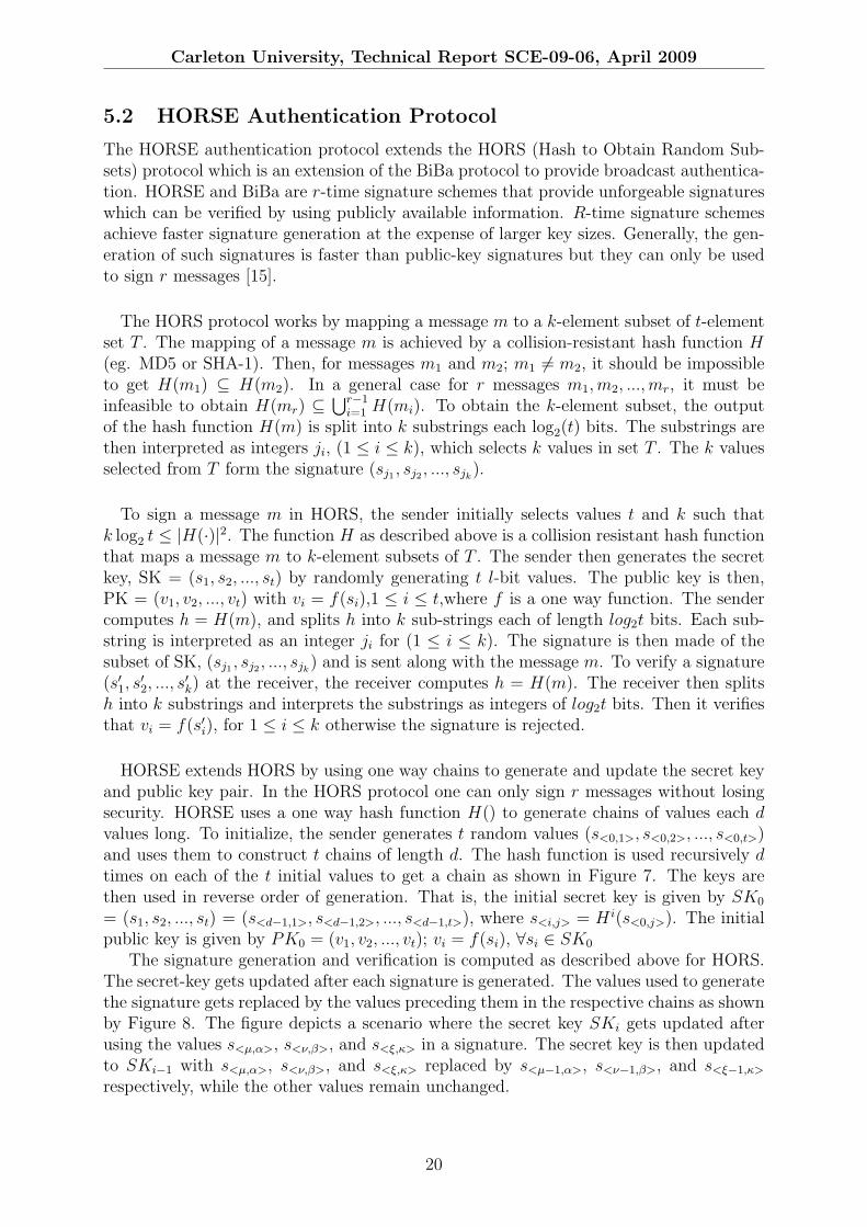
HORSE extends HORS by using one way chains to generate and update the secret keyand public key pair. In the HORS protocol one can only sign r messages without losingsecurity. HORSE uses a one way hash function H() to generate chains of values each dvalues long. To initialize, the sender generates t random values (s<0,1>, s<0,2>, ..., s<0,t>)and uses them to construct t chains of length d. The hash function is used recursively dtimes on each of the t initial values to get a chain as shown in Figure 7. The keys arethen used in reverse order of generation. That is, the initial secret key is given by SK0
= (s1, s2, ..., st) = (s<d−1,1>, s<d−1,2>, ..., s<d−1,t>), where s<i,j> = H i(s<0,j>). The initialpublic key is given by PK0 = (v1, v2, ..., vt); vi = f(si), ∀si ∈ SK0
The signature generation and verification is computed as described above for HORS.The secret-key gets updated after each signature is generated. The values used to generatethe signature gets replaced by the values preceding them in the respective chains as shownby Figure 8. The figure depicts a scenario where the secret key SKi gets updated afterusing the values s<µ,α>, s<ν,β>, and s<ξ,κ> in a signature. The secret key is then updatedto SKi−1 with s<µ,α>, s<ν,β>, and s<ξ,κ> replaced by s<µ−1,α>, s<ν−1,β>, and s<ξ−1,κ>
respectively, while the other values remain unchanged.
20
Carleton University, Technical Report SCE-09-06, April 2009
Figure 7: HORSE protocol
Figure 8: Updating the public and secret keys in HORSE
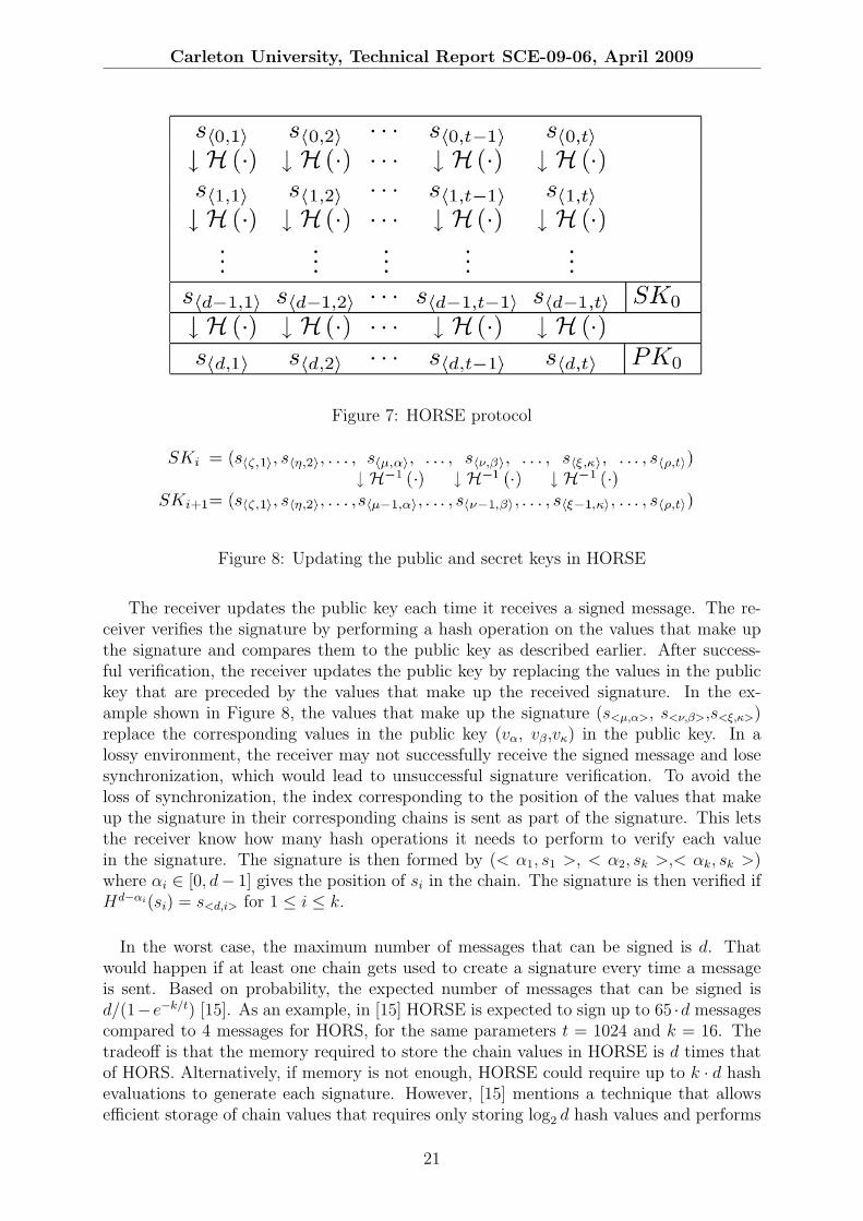
The receiver updates the public key each time it receives a signed message. The re-ceiver verifies the signature by performing a hash operation on the values that make upthe signature and compares them to the public key as described earlier. After success-ful verification, the receiver updates the public key by replacing the values in the publickey that are preceded by the values that make up the received signature. In the ex-ample shown in Figure 8, the values that make up the signature (s<µ,α>, s<ν,β>,s<ξ,κ>)replace the corresponding values in the public key (vα, vβ,vκ) in the public key. In alossy environment, the receiver may not successfully receive the signed message and losesynchronization, which would lead to unsuccessful signature verification. To avoid theloss of synchronization, the index corresponding to the position of the values that makeup the signature in their corresponding chains is sent as part of the signature. This letsthe receiver know how many hash operations it needs to perform to verify each valuein the signature. The signature is then formed by (< α1, s1 >, < α2, sk >,< αk, sk >)where αi ∈ [0, d− 1] gives the position of si in the chain. The signature is then verified ifHd−αi(si) = s<d,i> for 1 ≤ i ≤ k.
In the worst case, the maximum number of messages that can be signed is d. Thatwould happen if at least one chain gets used to create a signature every time a messageis sent. Based on probability, the expected number of messages that can be signed isd/(1−e−k/t) [15]. As an example, in [15] HORSE is expected to sign up to 65 ·d messagescompared to 4 messages for HORS, for the same parameters t = 1024 and k = 16. Thetradeoff is that the memory required to store the chain values in HORSE is d times thatof HORS. Alternatively, if memory is not enough, HORSE could require up to k · d hashevaluations to generate each signature. However, [15] mentions a technique that allowsefficient storage of chain values that requires only storing log2 d hash values and performs
21

Carleton University, Technical Report SCE-09-06, April 2009
at most log2 d hash evaluations per step.
5.2.1 Authenticating PCT Messages using HORSE
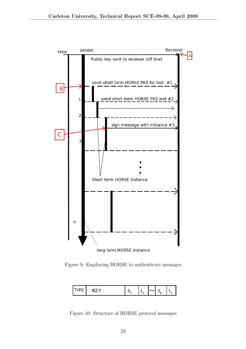
Each HORSE instance is expected to sign n = d/(1 − e−k/t) messages on average asexplained above. To sign messages exceeding d/(1− e−k/t), there is a need to use a newHORSE instance after the current one expires. To address the issue of signing messagesexceeding d/(1− e−k/t) messages, we propose a tired solution similar to the one employedfor using BiBa to sign PCT messages. A long-term HORSE instance is used to send theinitial public key of a new short-term HORSE instance when the current one expires. Theinitial public keys of the short-term HORSE instance are signed by the long-term HORSEinstance and sent to the receivers to allow the receivers to verify subsequent messages.Figure 9 shows the structure of the our construct to provide authentication for the PCTsystem.
An example to illustrate how the HORSE construct works is presented below:
• The initial public key of the long-term HORSE instance is sent to the receivers atthe time of installation. This is done by a technician installing the PCTs, shown inFigure 9 by label A.
• Short-term HORSE initial public keys are then sent to the receivers signed usingthe long-term HORSE private key as described above. Label B in Figure 9 shows ashort-term initial public key being sent to the receivers.
• Application messages are signed with the short-term HORSE instance as describedpreviously, shown by label C in Figure 9.
• Each short-term instance HORSE on average will send d/(1− e−k/t) messages afterwhich a new short-term HORSE instance needs to be created. When one of thechains in the short-term HORSE instance is about to be exhausted (left with say3 values), a new short-term HORSE instance is created and the public key is sentto the receivers. When the first chain is exhausted (left with 1 value), a message issent to the receivers to instruct them to use the last public key they received. Themessage sent to the receiver to switch to the new public key is encrypted with theexpiring short-term HORSE instance, such that the chain that had 1 value left haveall its values used.
A short-term HORSE with t = 1024, k = 4, and d = 50 on average will sign 12825 mes-sages before a new short-term instance is required. If the long-term HORSE instance hasthe same parameters, then 2565 short-term HORSE instances can be signed. Thereforeon average 128252 = 164480625 application messages can be signed. Keeping the previousapplication data rate of 20 messages per day, the construct can last 8224031 days (22531years).
5.2.2 HORSE Protocol Messages
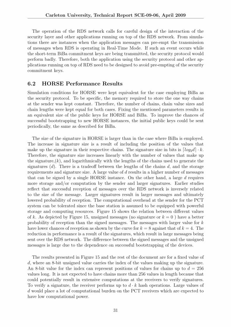
The protocol messages that are communicated to facilitate the use of HORSE for authen-tication in our solution follow the format used for BiBa (See Section 5.1.2). The structureof the messages is shown in Figure 10. The message fields are defined as follows:
22
Carleton University, Technical Report SCE-09-06, April 2009
Figure 9: Employing HORSE to authenticate messages
Figure 10: Structure of HORSE protocol messages
23

Carleton University, Technical Report SCE-09-06, April 2009
TYPE: Describes the type of data that is carried in the message.0 : Application messages are carried in the KEY field1 : Short-term HORSE instance public key is carried in the KEY field2 : Command to switch to newly received public key3 : Long-term HORSE commitment key. This option is not used if the long-termHORSE instance commitment is done off-line
KEY: The Data that is being sent in the message which is signed. Depending on thevalue of the TYPE field it can either be a message sent by the application or acommand to switch to the next HORSE instance, or short-term HORSE public key.
< S1, I1 >...< SK , Ik >: The signature formed by the k values that forms the subset (Si),and the index of the values in the chains(Ii); with 1 ≤ i ≤ k. The size depends onthe value of k.
The flow of messages will follow the same diagram as depicted by Figure 6
24

Carleton University, Technical Report SCE-09-06, April 2009
5.3 The Elliptic Curve Digital Signature Algorithm
Elliptic Curve Digital Signature Algorithm (ECDSA) is similar to the Digital SignatureAlgorithm (DSA), but employs elliptic curves over a finite field[16]. Elliptic curve cryptog-raphy offers faster verification and smaller keys for equivalent security with other publickey systems [17]. Based on the complexity of the Elliptic Curve Discrete LogarithmicProblem, it is computationally infeasible to forge a signature if appropriate parametersare employed.
A finite field F is made up of a finite number of elements together with two binary op-erations on F. The binary operations, addition and multiplication have special arithmeticproperties as defined in [16]. The order of a finite field is the number of elements in thefield. If p is a prime number, then the field Fp is called a prime field and is made up ofintegers {0,1,2,...,p− 1}. Addition and multiplication of elements of Fp are done modulop. That is a + b = r; where r = (a + b)mod p, and a · b = s ;where s = a · bmod p. Anelliptic curve E on a finite field Fp; where p > 3 is an odd prime, is given by the equation:
y2 = x3 + ax2 + b (1)
where p is a prime number, a, b ∈ Fp, and 4a3 + 27b2 6= 0(mod p). The set E(Fp) consistsof all points (x, y) (x, y ∈ Fp) that satisfy equation 1 and a point ϑ located at infinity.The point ϑ is the identity element of the group.
All the elements of the group have the properties:
P + (−P ) = (−P ) + P = ϑ
andP + ϑ = ϑ+ P = P
The security of elliptic curve cryptography comes from the Elliptic Curve DiscreteLogarithmic Problem (ECDLP). The ECDLP consists of finding a value k such thatP = kQ given P and Q ( with P,Q ∈ Fp ). There is no efficient known algorithm thatcan compute the value of k [17]. The parameter requirements to achieve resilience toknown attacks are outlined in [16]. [16] also gives ways of generating cryptographicallysecure parameters for elliptic curves using several methods.
To sign a message, initially the sender and receiver agree on an elliptic curve with abase point P over the field Fp. The sender has a private key x and a public key Q = xP .The parameters of the curve a, b, P, q, Fp as well as the public key Q are assumed knownto the receiver. To sign a message m:
1. The sender generates a random number k; k ∈ [1, n − 1] and then computes kP =(x1, y1). The value x1 is then converted to an integer x̄1
2. Compute r = x̄1mod n. If r = 0 then step 1 is repeated until r 6= 0.
3. Compute k−1mod n.
4. Compute SHA-1(m) and convert the output string into an integer e.
5. Compute s = k−1(e+ dr)mod n ; with s 6= 0. If s = 0 then go back to step 1.
25

Carleton University, Technical Report SCE-09-06, April 2009
6. The pair r,s form the signature and sent to the receiver.
When the receiver receives the signed message it performs the following steps to verifythe signature.
1. Confirm that r, s ∈ [1, n− 1].
2. Compute SHA-1(m) and convert the output string into an integer e.
3. Compute w = s−1mod n.
4. Compute u1 = ewmod n and u2 = rwmod n.
5. Compute X = u1P + u2Q. If X = ϑ reject the signature.
6. Covert the x coordinate of X to an integer x̄′1, and compute v = x̄′1mod n
7. Accept the signature if v = r
5.3.1 Authenticating PCT Messages using ECDSA
Authenticating PCT messages does not require a lot of changes to ECDSA. The use ofthe hash function SHA-1 in step 2 of signature generation can be omitted since the PCTmessages are small. Consequentially step 2 at the receiver will also be omitted resultingin less computations. The use of hash function is to obtain a fixed length string fromvariable message lengths . In practice the messages could be a file a few kilo bytes long,hashing it using SHA-1 results in a string 160 bits long.
The value n > 2160 is recommended to protect against attacks as outlined by [16].The sizes of the signature (r,s) is dependent on the value n, r, s ∈ [1, n − 1]. Taking aminimalist approach and using n = 2160, we have both r and s being 20 bytes long (thesignature is 40 bytes long). The above parameters can then be used for the PCT systemfor authentication purposes. It may be necessary to use a dynamic approach where theelliptic curve parameters used are refreshed periodically. To allow such a construct, thesender uses one long-term secret key to sign the new parameters when sending to themto the receivers.
26

Carleton University, Technical Report SCE-09-06, April 2009
6 Simulation Results and Analysis
The evaluation of the protocols was done using the Network Simulator tool (NS-2.30).The evaluation consists of building a model of the RDS network. The physical layerpropagation model was designed to match closely real conditions by conducting fieldmeasurements to calibrate the model. Signal strength readings of FM broadcasts weretaken from various places in Ottawa and used to characterize the channel gain. Thelocations for signal strength measurements were chosen randomly and are shown in Figure11. Readings were taken from two FM broadcast channels, Hot 89.9 (operation at 89.9MHz) and Bob FM (operationg at 93.9 MHz). Both stations have their transmittingantennas in Camp Fortune shown by the top left tag on Figure 11. Hot 89.9 transmitsat an effective radiated power (ERP) of 27 KW while Bob FM has an ERP of 95 kW.The signal strength measurements are presented in Figure 12 by the crosses (red). All thereadings were taken from indoors to reflect operation conditions for PCTs. The variationsof the signal strength readings as shown in Figure 12, are due to the different conditionsat the measurement sites. Some of the locations were on high rise apartment buildingswith potential line of sight conditions while others were in basement apartments. Othersites were in town houses with dry wall and wooden walls while others had concrete walls.All these different conditions have effects on the signal propagation and hence the signalreadings were diverse although they were taken from distances relatively similar from thetransmission antenna. Weather conditions and other unknown environmental effects alsoaccount for the vast differences in the readings. To account for the diverse nature of thedata, two approximations were made to reflect the best case and worst cases. Figure12 also shows the estimated signal strength obtained through simulations. The physicallayer signal propagation model used accounts for large scale fading channel by using theShadowing model provided in NS-2. The small scale channel fading was modeled by usinga Ricean model obtained from [18].Two pathloss exponents were used to account for thediverse data as shown in Figure 12. Taking a conservative approach the evaluation wasconducted for the worst case scenario hence the lower curve on Figure 12 was used toevaluate performance.
Figure 11: Locations of signal strength measurements
27

Carleton University, Technical Report SCE-09-06, April 2009
Figure 12: Estimation of the communication channel using field data
The media access of the model was designed to closely resemble the RDS network.That is, the fragmenting of messages into RDS groups was done to model the real network.Security is provided for by implementing the above the three authentication schemes inthe link layer. Table 1 shows the parameters of the RDS network used to evaluate thesecurity protocol. All results presented here, unless stated otherwise are based on theparameters in Table 1.
RDS Mode Real-TimeNumber of re-transmissions 5
Raw data bitrate 1187.5 bpsPropagation model pathloss exponent 3.50
Transmission power 27KWApplication Message size 30 Bytes
Table 1: Physical network parameters
6.1 BiBa Performance Results
From the simulations of the security protocol, a BiBa instance of 1024 SEAL chains wasfound to take 440 seconds (7.33 minutes) to bootstrap, assuming that no other applicationuses the network. Reducing the number of SEAL chains by half reduces the bootstrappingtime by half. Alternatively, SEALs of smaller size could be used to reduce the size of thepublic key. The time taken to bootstrap a new BiBa instance needs to be short to avoidperiods where the receiver is not synchronized with the sender. If such periods are allowed,the receiver will be unable to authenticate the new messages. To avoid such a problem,the last few time intervals (depending on the size of the short-term BiBa commitment key)of the current short-term BiBa instance could be used to bootstrap the next short-termBiBa instance.
The commitment keys used to bootstrap BiBa instances (public keys) are in the order ofa few kilo bytes. Successful reception of such messages over the lossy RDS channel becomes
28

Carleton University, Technical Report SCE-09-06, April 2009
a problem. Initial studies of the RDS network show that the probability of receivingmessages sent over the network is inversely proportional to the size of the message. Theprobability of receiving a message made up of m RDS groups and retransmitted n timesis given by P = (1 − P (fail)n)m; where P (fail) is the probability that a single RDSgroup is not received. The size of the BiBa commitment key using 512 SEAL chains(t = 512), with each SEAL 16-bits (2 Bytes) long for the short-term BiBa instance, thekey is m = 512∗2
RDS Group size= 256 groups; with (RDS Group size = 4). Such a large value
for m diminishes the probability of reception rapidly.
The trick mentioned earlier of avoiding unsynchronized periods between successive BiBainstances helps to increase the probability of receiving a new public key to an already syn-chronized node. This is because such a node effectively has 2 chances of receiving a thecommitment key for the next short-term BiBa instance. The first chance comes from usingthe long-term BiBa instance to bootstrap the new short-term BiBa instance. The secondchance comes from using the short-term BiBa instance to avoid unsynchronized periodsbetween successive short-term BiBa instances. To increase the chances of bootstrappingshort-term BiBa instances the number of times a public key is sent can be increased bysending commitment keys by both the long-term and short-term BiBa instances.
Different values for the number of SEALs in the short-term BiBa instance (t) havean impact on the reception of application messages. Figure 13 shows how the probabilityof receiving application messages vary with different commitment key sizes. The resultspresented in Figure 13 are for fixed SEAL sizes (16 bits). A larger value for t results ina larger commitment key which has lower probability of reception. It can be seen thatgenerally a larger value of t results in lower reception probability compared to smallervalues of t.
Figure 13: The effects of different of public key sizes on reception of messages
The reception of application messages depends largely on the successful bootstrap-ping of the BiBa instances at the receiver. When the receiver fails to bootstrap, all themessages received during that period will not be successfully verified. The results de-picted in Figure 14 show degraded performance against the case with no security becauseof the obvious bootstrapping problem caused by large commitment keys. More applica-tion messages are rejected by the security layer caused by unsynchronised receivers when
29

Carleton University, Technical Report SCE-09-06, April 2009
bootstrap information is not received. The successful reception of messages varies accord-ingly with the number of retransmissions of RDS groups. By increasing the number ofRDS re-transmissions, the reception of the individual messages and more importantly thecommitment keys, will be increased.
Figure 14: The effects of different signature sizes on reception of messages
The signature sizes are linear in k for a k-way BiBa signature, and public keys arelinear in the number of SEALs (t). The signed messages are bigger than unsigned messagesbecause of the signatures. Increasing the number of collisions required for the signature(k) increases the sizes of the transmitted message but also increases the security of theBiBa protocol by lowering the chances of an adversary to successfully forge a signature. Itis expected that messages bearing larger signatures incur lower reception at the receiverbased on initial studies of the RDS network. Figure 14 shows the probability of receivingmessages using different values of k. The graph on top shows the probability of reception ofmessages with no authentication. As shown by Figure 14, the messages of an 8-way BiBasignature scheme are less likely to be received than those of a 4-way BiBa scheme. Thedifference between the signed messages and unauthenticated messages is large becauseof the dependence on successful bootstrapping of receivers for signed messages. Thesuccessful bootstrapping of receivers diminishes fast with distance and effectively reducesthe coverage area that a Systems Operator can offer high availability of services.
The signatures introduce significant overhead to messages if the messages are small.An 8-way BiBa signature scheme with 16-bit SEALs has a 100% overhead on 16-Bytemessages without considering the bootstrap keys. The messages that are transmitted inthe PCT system are very small messages, in the order of tens of bytes. Therefore thesignature overhead is large and together with the communication of public keys, the BiBaprotocol as used in our design is not bandwidth efficient. However, if the SEAL chains arelong and each BiBa instance lasts for long periods of time, the consumption of bandwidthfor security reasons can be very small. If one commitment key is sent every 24 hours tobootstrap the receivers, then the bandwidth consumption by background traffic is small.For a short-term BiBa instance with 512 SEAL chains, each SEAL 2 Bytes long, thebandwidth consumption will be 512∗2∗8
24∗60∗60= 0.0948bps. With this construct, the availability
of the service would be increased by multiple transmissions of the commitment keys forthe short-term BiBa instance.
30
Carleton University, Technical Report SCE-09-06, April 2009
The operation of the RDS network calls for careful design of the interaction of thesecurity layer and other applications running on top of the RDS network. From simula-tions there are instances when the application messages can pre-empt the transmissionof messages when RDS is operating in Real-Time Mode. If such an event occurs whilethe short-term BiBa commitment keys are being transmitted, the security protocol wouldperform badly. Therefore, both the application using the security protocol and other ap-plications running on top of RDS need to be designed to avoid pre-empting of the securitycommitment keys.
6.2 HORSE Performance Results
Simulation conditions for HORSE were kept equivalent for the case employing BiBa asthe security protocol. To be specific, the memory required to store the one way chainsat the sender was kept constant. Therefore, the number of chains, chain value sizes andchain lengths were kept equal for both cases. Fixing the mentioned parameters results inan equivalent size of the public keys for HORSE and BiBa. To improve the chances ofsuccessful bootstrapping to new HORSE instances, the initial public keys could be sentperiodically, the same as described for BiBa.
The size of the signature in HORSE is larger than in the case where BiBa is employed.The increase in signature size is a result of including the position of the values thatmake up the signature in their respective chains. The signature size in bits is dlog2de · k.Therefore, the signature size increases linearly with the number of values that make upthe signature,(k), and logarithmically with the lengths of the chains used to generate thesignatures (d). There is a tradeoff between the lengths of the chains d, and the storagerequirements and signature size. A large value of d results in a higher number of messagesthat can be signed by a single HORSE instance. On the other hand, a large d requiresmore storage and/or computation by the sender and larger signatures. Earlier studiesreflect that successful reception of messages over the RDS network is inversely relatedto the size of the message. Larger signatures result in larger messages and ultimatelylowered probability of reception. The computational overhead at the sender for the PCTsystem can be tolerated since the base station is assumed to be equipped with powerfulstorage and computing resources. Figure 15 shows the relation between different valuesof k. As depicted by Figure 15, unsigned messages (no signature or k = 0 ) have a betterprobability of reception than the signed messages. The messages with larger value for khave lower chances of reception as shown by the curve for k = 8 against that of k = 4. Thereduction in performance is a result of the signatures, which result in large messages beingsent over the RDS network. The difference between the signed messages and the unsignedmessages is large due to the dependence on successful bootstrapping of the devices.
The results presented in Figure 15 and the rest of the document are for a fixed value ofd, where an 8-bit unsigned value carries the index of the values making up the signature.An 8-bit value for the index can represent positions of values for chains up to d = 256values long. It is not expected to have chains more than 256 values in length because thatcould potentially result in extensive computations at the receivers to verify signatures.To verify a signature, the receiver performs up to d · k hash operations. Large values ofd would place a lot of computational burden on the PCT receivers which are expected tohave low computational power.
31
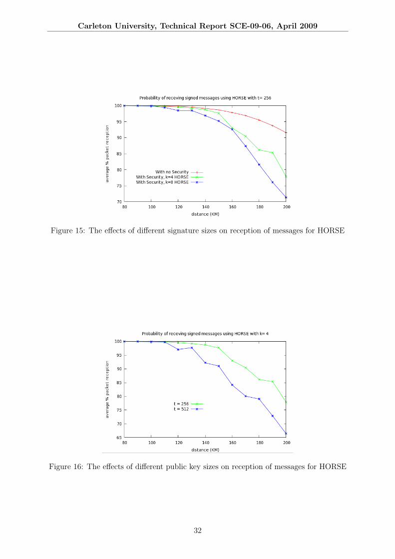
Carleton University, Technical Report SCE-09-06, April 2009
Figure 15: The effects of different signature sizes on reception of messages for HORSE
Figure 16: The effects of different public key sizes on reception of messages for HORSE
32

Carleton University, Technical Report SCE-09-06, April 2009
Successful reception of initial public keys is critical for the verification of signatures. Thelarger the signatures, the more likely that the initial public key is not received successfully.In this case, the receiver will not be synchronized with the sender and will fail to verifysigned messages. Figure 16 shows the effect of varying values of t. The size of the publickey grows linear with respect to t. To keep the cases with different values of t equivalent,the value t · d was kept constant in all cases. That is, the amount of storage required bythe sender is the same in all cases. The results are as expected with larger values of tperforming worse than smaller values. This is shown in Figure 16 with t = 128 performingbetter than t = 256 which in turn performed better than t = 512.
From the results in Figure 16, it is evident that keeping t as small as possible and keepingd as large as possible improves improve successful initial key reception by reducing thesize of the public key. As pointed out earlier, the number of operations at the receiver isequal to k · d. For a fixed value of k, increasing d (and reducing k) will result in increasedcomputations at the receivers.
6.3 ECDSA Performance Results
Figure 17: The performance of ECDSA used over the RDS network
The ECDSA protocol produces large signatures compared to BiBa and HORSE. Forthe recommended 160-bit key (according to [16]) ECDSA has a signature of 40 bytes.This introduces a lot of overhead in the case of PCT messages which are expected to bea few tens of bytes in size. The large messages result in lowered performance as shownby Figure 17. It is worth noting that although the overhead on each message is large forECDSA, the successful verification of signatures does not depend on receiver bootstrapas is the case with BiBa and HORSE.
6.4 Comparing the Authentication Protocols
Figure 18 puts things in perspective and compares the performance of all the protocolsagainst each other. Figure 18 shows the reception of messages signed by each of theauthentication protocols under investigation. From the simulation results as shown in
33

Carleton University, Technical Report SCE-09-06, April 2009
Figure 18: Comparisons between BiBa, HORSE and ECDSA
Figure 18, HORSE performs better than BiBa in terms of successful reception of messages.For the same values of k and t, HORSE has a significant advantage over BiBa as shownin the figure. As an example, at a distance of 14 km, HORSE with t = 256 and k = 4gives 5% better message reception than BiBa with the same parameters. The difference inperformance increases as the distance increases, reaching 20% at a distance of 18 km. Theperformance improvement in HORSE comes from efficient use of chain values. In BiBa,the short-term BiBa instance expires when the time set for it elapses even if there areno application messages sent during that period. This results in frequent transmission ofthe large commitment keys (public keys) which have low chances of successful reception.From the figure, there is no significant difference between HORSE with t = 256 and k = 4and ECDSA. It is worth noting that with HORSE the values of t and k can be adjustedto improve performance, albeit with tradeoffs mentioned previously.
ECDSA has large signatures on each message and had overhead of40
30∗100% = 133.33%
on a 30 byte message (the signature is 40 bytes long). A HORSE instance with parameterst = 256, k = 4, and d = 20 introduces only 41.32% overhead. Such a HORSE instancecan be used to sign d/(1− e−k/t) = 1290 messages. Each message is 30 bytes long and thesignature on each message is k(b+a) = 12 bytes long(where b = 2 and a = 1; i.e. each valuein that make up signature is 2 bytes long and the index variable used for synchronizationis 1 byte long). The public key sent to the receivers is t ∗ 2 = 512 bytes long, and sent
only once. Therefore, the overhead is512 + (12)1290
30(1290)∗ 100% = 41.32%. It is important
to notice that the overhead of the HORSE protocol will increase with periodic sendingof initial public keys to improve bootstrapping probability. The overhead of the BiBa
protocol with the same parameters in the best case is equal to512 + (8)30νd
30νd∗ 100% =
30.08%;(with d = 20, and ν = b tγkc = 25 ; typically γ = 0.10). The best case for BiBa
that achieves the above overhead is when the maximum number of messages is signed ineach time interval. That is, for the above parameters in each of the d = 20 time intervals,ν = 25 messages are signed. The number of signed messages in each interval is expectedto be less than the maximum hence the overhead will be larger. The increase in overhead
34

Carleton University, Technical Report SCE-09-06, April 2009
is a result of is inefficient use of keys in BiBa. If the BiBa instances are bootstrappedmultiple times to improve successful reception of messages, the overhead is even higher.
The computations that the receivers have to perform when ECDSA is employed forauthentication are extensive. In general public key cryptography are computationallyextensive because of the arithmetic involved in signature generation and verifications.Public key cryptosystems perform complex operations on relatively large numbers (160bits for ECDSA). The PCTs are expected to employ low power microcontrollers withlimited computational power. Implementations of ECDSA on an 8-bit processor takes 2.78seconds to verify a signature [19]. On a slightly more powerful 16-bit M16C microcontrollerECDSA was shown to require 630 msec to verify a signature [20]. Comparisons betweenDSA and HORSE on a PPC 867 MHz platform show that a HORSE implementationusing MD5 with t = 256, k = 16, d = 210 has a key generation time of 0.63 seconds andcan verify 2688 signatures in one second [15]. An equivalent DSA has a key generationtime of 2.66 seconds and can verify 108 signtures in one second [15] (note that ECDSA isbased on DSA). The time required for signature verification in ECDSA is very similar toDSA as shown in [21]. [21] compares software implementations of ECDSA and DSA on aPentium Pro 200 MHz-based PC to give a perspective on relative performance of ECDSAand DSA. The results show that ECDSA requires 26 ms to verify a signature while DSArequire 28.3 ms to verify a signature. HORSE gives a faster signature verification timethan DSA (on which ECDSA is based) and a designer faces a tradeoff between the twoschemes. The fast verification time of HORSE is ideal for PCT’s which are expected toemploy microprocessors with modest computational power. The use of HORSE allows forrelatively cheap devices at the cost of longer periods to bootstrap the devices. ECDSAdoes not require bootstrap but requires the devices to perform complex operations andhence take longer times to verify signatures. The time taken to verify a signature couldbe exploited by an attacker allowing a denial of service attack. If the receivers take a longtime to verify a signature, an attacker who floods the network with messages will take upresources at the receivers while they verify the signatures. This could result in missinglegitimate messages while the receivers are verifying the bogus messages. Moreover batterypowered devices would be unable to go into powersaving modes because they would be keptbusy verifying bogus messages, ultimately leading to reduced battery life and increaseddown times of the receivers.
Security Overhead 95% service security level computationalscheme availability (probability of guessing effort
(KM) a valid signature) (at receiver)ECDSA 133.33% 120 2−80 HighHORSE 41.32% 130 2−35 Low
BiBa 30.08% 120 2−35 Low
Table 2: Comparisons of the security schemes for BiBa and HORSE with t = 512 andk = 4,and ECDSA using SHA-1
Comparisons of the security schemes is presented in Table 2. The table shows thebandwidth overhead introduced by the different security schemes. ECDSA has the mostoverhead compared to the other schemes. The overhead of HORSE and BiBa as presentedin the table is a lower bound and in practice will be higher depending on the number of
35

Carleton University, Technical Report SCE-09-06, April 2009
times public keys are sent to the receivers. The use of signatures makes messages largerwhich in turn results in increased message loss-rate. Distances from the transmitter atwhich 95% of the messages are correctly received with the network parameters set as inTable 1 are also presented from simulations. Up to a distance of 90 km all the securityschemes achieve high availability of services. Beyond that rane, messages may not bereceived correctly. The loss of messages is due to signatures and failure to bootstrapreceivers for BiBa and HORSE protocols. The security level provided by the schemes interms of successfully forging a signature by guessing is presented in Table 2. ECDSA givesa high level of security with a cost of added computational complexity at the receivers.BiBa and HORSE offer reduced security and lower computational cost at the receivers.Reversing the one way hash function used in ECDSA, BiBa and HORSE should be com-putationally infeasible, hence strong hashing algorithms should be employed. An attackerwho cannot obtain private key material from the transmitter and tries to forge a signatureis limited to guessing. The probability that an attacker can successfully forge an ECDSAsignature is 2−80 while for HORSE and BiBa it is 2−35 [14].
36

Carleton University, Technical Report SCE-09-06, April 2009
7 Conclusions
Through the study we have shown that security (in the form of message authentication)can be offered over the RDS system. The security provided by the three protocols providessource authentication at a cost of bandwidth efficiency. The construct allows for seamlessoperation of devices after initialization. The use of a long-term BiBa and HORSE instanceallows devices that were rebooted to resynchronize to current short-term instances. Thelarge size of the public keys of the BiBa and HORSE protocol affects the performance,which is dependent on the successful bootstrapping of devices. Although the transmissionof the public key for both BiBa and HORSE may take a long time, careful schedulingof such actions for periods with minimal traffic can improve performance. Comparisonsshows that the performance of ECDSA is comparable to HORSE. HORSE allows to adjustkey sizes and signature sizes to improve performance and reduce overhead. ECDSA onthe other hand gives a fixed signature size and introduces significantly higher messageoverhead compared to BiBa and HORSE. Hybrids of the schemes should be consideredfor the purposes of making the scheme resilient to attacks and conserve bandwidth.
The protocol employing BiBa and HORSE described here places constraints on theapplication data rate. The protocol assumes an upper bound of the application data rate.A single BiBa instance can be used to sign a finite number of messages in a single timeinterval before the security of the protocol falls below targeted levels. In the event that anapplication exceeds the number allowed by the protocol within a time interval, a decisionneeds to be made to either buffer such messages until the next period, send the messagesunsigned, or sign the message, albeit with reduced security. Buffering some messages maynot be ideal for real-time messages, while some critical messages require authentication atthe receivers. A more relaxed design is recommended to avoid placing tight constraints onthe application. A tradeoff between the public key sizes and the bound on the applicationmessage generation rate exist. Smaller public keys means fewer messages can be signedin a single period. Allowing for many messages to be sent in a single period requires thateither multiple short-term BiBa instances run in parallel or one short-term BiBa instancewith a large number of SEAL chains. The results of both choices effectively increases thesize of the commitment keys and ultimately results in increased bootstrapping times anda lowered probability of successful bootstrapping of receivers.
The problem of key distribution still persists with the methods discussed. In the eventthat a long-term secret key is compromised, there is no feasible way at present to renewit for all the protocols presented. The difficulty is inherent due to the asymmetric natureof the channel. Traditional key agreement and distribution protocols cannot be employedon a one-way communication channel like RDS. Further studies should be conducted topropose manageable ways of system recovery in the event of a long-term chain compromise.
37

Carleton University, Technical Report SCE-09-06, April 2009
References
[1] E. W. Gunther, “Reference Design for Programmable Communicating ThermostatsCompliant with Tite-24.” CEC PIER PCT Reference Design, 26 March 2007.
[2] “Security Characteristics of the Title-24 PCT System,” 12 April 2007.
[3] M. Daucher, E. Gartner, M. Cortler, W. Keller, and H. Kuhr, “RDS-Radio DataSystem; A Challenge and a Solution,” Fujitsu Ten Technical Journal, 30 November2008.
[4] S. C. Bono, M. Green, A. Stubblefield, A. Juels, A. D. Rubin, and M. Szydlo, “Secu-rity Analysis of a Cryptographically Enabled RFID Device,” 14th USENIX SecuritySymposium, pp. 1–16, August 2005.
[5] A. Juels, “RFID Security and Privacy: A Research Survey,” Selected Areas in Com-munications, IEEE Journal on, vol. 24, pp. 381–394, February 2006.
[6] S. W. Ari Juels, Advances in Cryptology - CRYPTO 2005, vol. 3621/2005. SpringerBerlin / Heidelberg, 2005.
[7] M. FeldHofer, Cryptographic Hardware and Embedded Systems - CHES 2004,vol. 3156/2004. Springer Berlin / Heidelberg, 2004.
[8] A. Treytk, N. Roberts, and G. P. Hanke, “Security Architecture for Power-line Me-tering System,” Factory Communication Systems, 2004. Proceedings. 2004 IEEE In-ternational Workshop on, pp. 393– 396, 22-24 Septempber 2004.
[9] T. Mander, H. Cheung, A. Hamlyn, and R. Cheung, “Communication Security Ar-chitecture for Smart Distribution System Operations,” Electrical Power Conference,2007. EPC 2007. IEEE Canada, pp. 411–416, 25-26 October 2007.
[10] P. Gibson, “Keeping scada open and secure,” June 2008.
[11] D. K. T. Kunz, “RF Fingerprints for Secure Authentication in Single-Hop WSN,”Networking and Communications, 2008. WIMOB ’08. IEEE International Confer-ence on Wireless and Mobile Computing, pp. 567–573, 12-14 October 2008.
[12] S. J. Engberg, M. B. Harning, and C. D. Jensen, “Zero-knowledge device authen-tication: Privacy & security enhanced rfid preserving business value and consumerconvenience,” in PST, pp. 89–101, 2004.
[13] A. Perrig, R. Canetti, J. D. Tygar, and D. Song, “The tesla broadcast authenticationprotocol,” RSA CryptoBytes, vol. 5, p. 2002, 2002.
[14] A. Perrig, “The BiBa One-time Signature and Broadcast Authentication Protocol,”Proceedings of the 8th ACM conference on Computer and Communications Security,pp. 28–37, 5-8 November 2001.
[15] W. Neumann, “HORSE: An Extension of an r-Time Signature Scheme With FastSigning and Verification,” Information Technology: Coding and Computing, 2004.Proceedings. ITCC 2004. International Conference on, vol. 1, pp. 129–134 Vol.1,April 2004.
38
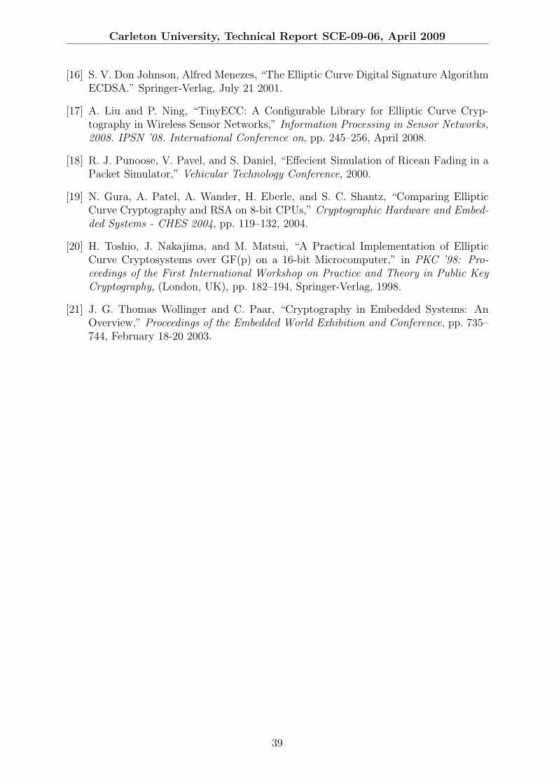
Carleton University, Technical Report SCE-09-06, April 2009
[16] S. V. Don Johnson, Alfred Menezes, “The Elliptic Curve Digital Signature AlgorithmECDSA.” Springer-Verlag, July 21 2001.
[17] A. Liu and P. Ning, “TinyECC: A Configurable Library for Elliptic Curve Cryp-tography in Wireless Sensor Networks,” Information Processing in Sensor Networks,2008. IPSN ’08. International Conference on, pp. 245–256, April 2008.
[18] R. J. Punoose, V. Pavel, and S. Daniel, “Effecient Simulation of Ricean Fading in aPacket Simulator,” Vehicular Technology Conference, 2000.
[19] N. Gura, A. Patel, A. Wander, H. Eberle, and S. C. Shantz, “Comparing EllipticCurve Cryptography and RSA on 8-bit CPUs,” Cryptographic Hardware and Embed-ded Systems - CHES 2004, pp. 119–132, 2004.
[20] H. Toshio, J. Nakajima, and M. Matsui, “A Practical Implementation of EllipticCurve Cryptosystems over GF(p) on a 16-bit Microcomputer,” in PKC ’98: Pro-ceedings of the First International Workshop on Practice and Theory in Public KeyCryptography, (London, UK), pp. 182–194, Springer-Verlag, 1998.
[21] J. G. Thomas Wollinger and C. Paar, “Cryptography in Embedded Systems: AnOverview,” Proceedings of the Embedded World Exhibition and Conference, pp. 735–744, February 18-20 2003.
39