security of fixed and wireless computer networks
TRANSCRIPT

Security of fixed and wireless computer networks
Jan Verschuren1, Sander Degen2, and Thijs Veugen2
1TNO ITSEF BV P.O. Box 96864
2509 JG The Hague The Netherlands
2TNO-Telecom P.O. Box 5050 2600 GB Delft The Netherlands
[email protected] [email protected]
Abstract. A few decades ago, most computers were stand-alone machines: they were able to process information using their own resources. Later, computer systems were connected to each other enabling a computer system to exchange data with another computer and to use resources of another computer. With the coupling of computer systems, security items emerge: in general the link between computers is not protected by thorough physical means. That enables an attacker to tap or modify information on the link. In this article, a description of the architecture of a wired and a wireless computer network is given. For both types of networks, threats to the process of information exchange are indicated. Security services and security mechanisms are addressed aiming to secure the information exchange between computer systems.
1 Introduction Formerly, computer systems were mainly stand-alone: a computer was able to process programs (also referred to as application programs (APs)) using its resources. Later computers were coupled by means of a network. The possibility to exchange data between computers was considered to be an advantage. The distributed configuration offered for example the possibility to store data at only one location. Besides it became possible to run jobs on other computer systems, if one’s own computer was not able to do so and to exchange data (e-mail, web-pages). In this article we will address security items which are specific for the distributed configuration. In order to do so we start by describing a network architecture. We will discuss wired as well as wireless computer networks (sections 2 and 5). For both cases threats will be identified (sections 3 and 6). Subsequently, we will indicate measures aiming to prevent threats from being harmful (sections 4, 7 and 8). Section 9 concludes the article. 2 Communication Between Computer Systems A computer system can be schematically represented by figure 1.

Fig. 1. Schematic representation of a computer system An application program AP is executed by means of the operating system OS, which is built on a hardware platform. Via an I/O channel, the Application Program can retrieve and transmit information. By means of I/O channels, the user can communicate with the computer system. I/O channels also provide a possibility to connect the computer system to a medium. Thus it is possible that an AP communicates with an AP running on another computer system. The medium may be a simple link, it can also be a network to which more computer systems are connected. A so-called communication subsystem is responsible for the transfer of DATA-blocks form the sending AP (APs) to the receiving AP (APr). In order to do so, the communication subsystem appends control information (e.g. the address of the destination) to the DATA-blocks to be transmitted. Thus the communication subsystem controls the information exchange between two APs on two computer systems. This is illustrated in figure 2. Fig. 2. AP – AP communication via a network
I/O
OS
hardware
AP
Other I/O Other I/O OS
hardware
APs DATA DATA
Communication subsystem
Communication subsystem
Network
Control info DATA Control info DATA
hardware
OS
APr

Several communication subsystems exist. In this article we concentrate on the communication subsystem according to the ISO-Reference Model for Open Systems Interconnection and TCP/IP Reference Model. 2.1 The ISO Reference Model for Open Systems Interconnection The ISO Reference Model for Open Systems Interconnection consists of 7 layers, which form together the communication subsystem (figure 3), [1], [2]. Fig. 3. Overall structure of the ISO-Reference Model
Real systems environment
Computer B
A-layer (7)
P-layer (6)
S-layer (5)
T-layer (4)
N-layer (3)
L-layer (2)
P-layer (1)
Data-network
Network environment
OSI-environment
Computer A
Application layer
Presentation layer
Session layer
Transport layer
Network layer
Link layer
Physical layer
AP AP

The layers can be indicated by means of their names or by means of a number N (N = 1, 2,…,7). Each layer performs a well-defined function in the context of the communication between two APs. It operates according to a defined protocol. Protocols are sets of rules that govern the exchange of information between two entities. Performing this protocol results in the exchange of Protocol Data Units (PDUs) between two (protocol) entities that belong to the same layer. PDUs which are exchanged between two protocol entities of layer N are referred to as N-PDUs. These are transported by invoking services provided by the lower layer. More specifically, the N-PDU (which is also named (N-1)-SDU: N-1 Service Data Unit) is a parameter of a service request, which is issued by the N-layer to the (N-1)-layer. Subsequently the (N-1)-protocol entity will feel the need to exchange an (N-1)-PDU with a peer entity of layer (N-1). The (N-1)-PDU will be equal to the N-PDU concatenated with a so called PCI-block (protocol control information block) which will contain at least the source and the destination addresses of the service access points of the two communicating protocol entities. This PCI-block governs the PDU-exchange between the protocol entities as it helps the receiving protocol entity to correctly interpret the received PDU. At an (N-1)-service access point ((N-1)-SAP) a protocol entity of layer N can invoke a service provided by a protocol entity of layer (N-1). Figures 4 and 5 illustrate the exchange of PDUs between protocol entities. Fig. 4. Interactions between protocol entities in the same system
Layer N+1
Layer N
Layer N-1
(N+1)-PDU
N-SAP
N-PCI N-SDU
PCI (N+1)-PDU N-PDU
(N-1)-SAP
Primitive type
Called address
Calling address
....
(N+1)-PDU (N-SDU)
Primitive type
Called address
Calling address
....
N-PDU ((N-1)-SDU)

Fig. 5. Interactions between protocol entities in different systems The functions of the different layers can be described as follows: �� the physical layer transforms the information to be sent (represented in bits) to (physical) signals which can be
transported by the transmission medium �� the link layer provides the network layer with a reliable information transfer facility. It is thus responsible for
such functions as error detection and, in the event of transmission errors, the retransmission of messages �� the network layer is responsible for the establishment and clearing of a network wide connection between two
transport layer protocol entities. It includes facilities as network routing (addressing) �� the transport layer provides the session layer with a reliable data transfer facility which is independent of the
type of network which is being used to transfer the data �� the session layer is responsible for establishing and synchronizing the dialogue between APs. Synchronising a
dialogue means that the dialogue can be resumed from specific synchronization points in case of errors
Physical
Link
Network
Transport
Session
Presentation
Application
AP
PCI NPDU
PCI TPDU
PCI SPDU
PCI PPDU
PCI APDU
PCI A-SDU
Physical
Link
Network
Transport
Session
Presentation
Application
AP DATA
Encoded bitstream

�� the presentation layer performs the conversion from an abstract syntax (e.g. type character) to a concrete syntax (e.g. ASCII) and vice versa. Figure 6 illustrates this. (PSAP denotes the Service Access Point (SAP) between the application layer and the presentation layer.)
Fig. 6. Function of the presentation layer �� The application layer enables APs to get access to a range of network wide distributed information services. For
instance an AP can get access to a remote file server AP that enables the requesting AP to get access to files managed by the file server AP.
As mentioned before, an N-protocol entity has to transmit PDUs (N-SDUs) – which it gets as a parameter in a service request – to a peer protocol entity. Two possible ways exist to do this. 1) The entity first establishes a connection with the peer entity. If this is settled, then the N-SDU in question is
transmitted via the connection. This is referred to as a “connection oriented” service. 2) The N-SDU is transmitted without first establishing a connection. This is denoted by the term “connectionless”
service. Out of the foregoing it turned out that the network layer is responsible for routing PDUs between computer systems. A schematic representation of a network of computer systems is given in figure 7. Fig. 7. Computer network
node Computer system
A-layer
PSAP
P-layer
A-L
PSAP
P-L
Data in a suitable transfer (concrete) syntax
Data in an agreed
abstract syntax
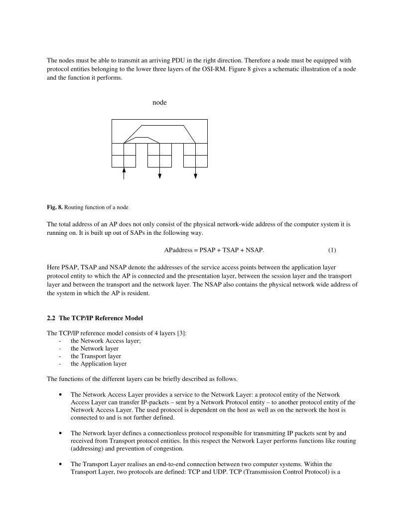
The nodes must be able to transmit an arriving PDU in the right direction. Therefore a node must be equipped with protocol entities belonging to the lower three layers of the OSI-RM. Figure 8 gives a schematic illustration of a node and the function it performs. Fig. 8. Routing function of a node The total address of an AP does not only consist of the physical network-wide address of the computer system it is running on. It is built up out of SAPs in the following way.
APaddress = PSAP + TSAP + NSAP. (1) Here PSAP, TSAP and NSAP denote the addresses of the service access points between the application layer protocol entity to which the AP is connected and the presentation layer, between the session layer and the transport layer and between the transport and the network layer. The NSAP also contains the physical network wide address of the system in which the AP is resident. 2.2 The TCP/IP Reference Model The TCP/IP reference model consists of 4 layers [3]:
- the Network Access layer; - the Network layer - the Transport layer - the Application layer
The functions of the different layers can be briefly described as follows.
• The Network Access Layer provides a service to the Network Layer: a protocol entity of the Network Access Layer can transfer IP-packets – sent by a Network Protocol entity – to another protocol entity of the Network Access Layer. The used protocol is dependent on the host as well as on the network the host is connected to and is not further defined.
• The Network layer defines a connectionless protocol responsible for transmitting IP packets sent by and
received from Transport protocol entities. In this respect the Network Layer performs functions like routing (addressing) and prevention of congestion.
• The Transport Layer realises an end-to-end connection between two computer systems. Within the
Transport Layer, two protocols are defined: TCP and UDP. TCP (Transmission Control Protocol) is a
node

connection-oriented protocol with error correction. UDP (User Datagram Protocol) is an unreliable, connectionless protocol. The Transport layer provides the Application layer with a data transfer facility independent of the type of network used for the data transfer.
• The Application Layer enables APs to get access to a range of network wide distributed information
services. In this respect FTP (file-transfer), SMTP (electronic mail) and HTTP (enabling the transmission of pages from the World Wide Web) can be mentioned.
2.3 Comparison between the OSI and TCP/IP reference models The OSI-RM and the TCP-IP reference model have much in common. Both are based on the idea of a set of independent protocol layers. The most concrete differences between the two reference models point to the number of layers and to the functionalities of the Network and Transport layer. The number of layers of the OSI-RM and the TCP/IP reference model OSI has 7 layers, TCP/IP has 4. Both reference models have an application, transport and (inter-)network layer. The other layers show differences. The following figure visualises both models. Fig. 9. OSI and TCP/IP reference models Difference with respect to the functionality of the N-layer and T-layer Within the N-layer the OSI-RM offers a connection-oriented and a connectionless service. TCP/IP only offers a connectionless communication service at the N-layer. At the T-layer, the OSI-RM only offers a connection-oriented communication service whereas TCP/IP enables both a connection-oriented as well as a connectionless service. A complete comparison between the two reference models can be found in [4].
OSI
Application layer
Presentation layer
Session layer
Transport layer
Network layer
Link layer
Physical layer
AP
TCP/IP
Application layer
Transport layer
Network layer
Network access layer
AP
Not defined

3 Threats The fact that information transferred between two computers is transported via a public medium (e.g. a telephone network), makes it extra vulnerable in comparison with information exchanged between APs both running on the same stand-alone system. More specifically, data in stand-alone systems is not easily available whereas data transported via public networks is: in general public media are not protected by a physical barrier. Therefore everyone can easily tap information or even modify it. Thus two forms of attacks can be discerned. �� Passive attacks resulting in unauthorized disclosure of information �� Active attacks resulting in modification of the transmitted information. From section 2.1 it turned out that the information, which is transferred via the data communication network is twofold: �� User data �� Data governing the communication between two entities (protocol control information) So passive attacks can result in the disclosure of user data and of information concerning the communication (e.g. the addresses of the sending and receiving computer system). Active attacks intend to modify user data or PCI-blocks. Changing the address of the sending computer system is an example of modifying the PCI-block. That will make the receiver think that the data came from another system. The threats just mentioned refer to the situation where two APs are already communicating. Prior to this phase, the communication must be started: an AP attempts to set up a connection with another AP. Then it must be decided if the two APs are allowed to communicate with each other. More specifically, it must be prevented that an AP uses resources (e.g. data belonging to another AP) in an unauthorized way. After the data has been transmitted from sender to receiver, other threats are present: �� The receiver states it did not get the data �� The sender states it did not send the data. So the threats to be envisaged, can be summarized as follows: �� Unauthorized access to resources �� Disclosure or modification of transmitted data �� False statements of entities, which sent or received data. 4 Realisation of Security Services Protection needs to be supplied to counter the threats as mentioned in section 3. This protection can be realized by means of security services. We can discern two principal locations where these security services can be implemented.
1) In the communication subsystem By means of a communication subsystem an AP can exchange information with another one. So the communication subsystem provides an AP with the functionality of a communication link. Implementing

security services into the communication subsystems, leads to a situation where the AP is provided with a secure communication link. Below we will discuss possibilities of introducing security services in the OSI and TCP/IP reference models.
2) At the level of the Application Program Incorporating security services in the AP, leads to a situation where the AP itself builds a secure link irrespective of the offered communication link. This option is further dealt with in section 4.3.
4.1 Security Services in the OSI-RM In section 3 threats to user data and protocol control information were mentioned. In ISO 7498-2 [5] 5 classes of security services are defined. Their goal is to prevent the threats from being successful. The security services defined in ISO 7498-2 are the following ones. Authentication This service can take two forms: peer entity authentication and data origin authentication. The first one refers to a connection-oriented mode of transmitting PDUs, the second one assumes a connectionless mode. • Peer entity authentication: the corroboration that a peer entity in an association is the one claimed. • Data origin authentication. The corroboration that the source of data received is as claimed. Access control This service provides protection against unauthorised use of resources accessible via OSI. These may be OSI or non-OSI resources accessed via OSI-protocols. This protection service may be applied to various types of access to a resource (e.g. the use of a communications resource; the reading, writing or the deletion of an information resource; the execution of a processing resource) or to all accesses to a resource. Confidentiality The confidentiality security service aims to protect transmitted information so that it is not made available or disclosed to unauthorised individuals, entities or processes. The confidentiality services can take different forms: confidentiality services are defined depending on the kind of connection (connectionless or connection-oriented). Besides it is also possible to protect part of a PDU transmitted between two protocol entities. In addition also the traffic flow confidentiality service is defined. The traffic flow confidentiality service provides for the protection of the information which might be derived from observation of traffic flows: the traffic flow confidentiality service aims to protect against traffic analysis. Integrity Integrity points to the property that data has not been altered or destroyed in an unauthorised manner. Security services are defined aiming to detect modification, insertion, deletion or replay of transmitted data. These security services can take different forms depending on the type of connection (connectionless or connection-oriented). If the security service of the receiver detects errors in the received data, the security service can ask for a retransmission of the data (Integrity service with recovery). Simpler security services do not ask for a recovery. Moreover security services are defined aiming to protect the integrity of only part of the transmitted PDU. Non-repudiation Repudiation refers to the situation where one of the entities involved in a communication denies having participated in all or part of the communication.

In ISO 7498-2 the following two variants of the non-repudiation security service are discerned. Non-repudiation with proof of origin The recipient of data is provided with proof of origin of data which will protect against any attempt by the sender to falsely deny having sent the data. Non-repudiation with proof of delivery The sender of data is provided with proof of receipt of data which will protect against any attempt by the recipient to falsely deny having received the data or its contents. Part 2 of ISO 7498 gives guidelines at which layer(s) the security services described above can be provided. Making a choice out of the possibilities depends on the security policy of the two APs. A security policy specifies what information is sensitive and indicates how it has to be protected [6]. Each AP tries to follow a certain security policy when communicating with another AP. If both policies do not agree initially, then negotiation is necessary. If this is successful, then the agreed security policy will result in a set of invoked security services applicable to the communication. More specifically, not all security services available need to be used for each information exchange. Consider for example the situation of e-mail communication. In some cases the sender and receiver require the confidentiality of the exchanged e-mail messages. In other situations, the non-repudiation service is considered vital. For realising the security services, so called security mechanisms have to be applied. E.g. the confidentiality service can be realised by the encipherment mechanism but also by routing the data via a special communication path, e.g. via one or more secure subnetworks. ISO 7498-2 describes security mechanisms (e.g. encipherment, techniques for digital signature, routing control) which can be used to realise a security service. To give an idea of the effect of placing a security service at different layers examples with respect to three security services will be given. Confidentiality Encipherment at two different layers is considered.
• Application layer • Physical layer
As was described in chapter 2, the nodes of the network are equipped with protocol entities belonging to the three lower layers of the OSI-RM. This implies that encipherment of the information at the application layer does not cause problems: the nodes can read and interpret the address information in the PCI-block added by the network-layer as this is not enciphered. Encipherment applied at the transport or application layer is referred to as end-to-end encryption as during transport no deciphering of the PDUs takes place; they are deciphered for the first time when they arrive at their destination. Encipherment at the physical-layer necessitates decipherment of the PDU at the intermediate nodes to enable the node to determine the direction in which it has to send the PDU. This implies that at the node the whole PDU (including the user data sent by the AP) is in the clear. This may be unacceptable for the communicating APs. Encipherment at the physical layer has an advantage however. It will imply that an enemy who taps the line will see nothing of the structure of the information. He will therefore be unaware of the sources and destinations of messages and may even be unaware whether messages are passing at all. This provides ‘traffic-flow confidentiality’ meaning that not only the information, but also the knowledge of where the information is flowing and how much is flowing is concealed from the enemy. By implementing encipherment at the lowest level, traffic-flow confidentiality can be obtained.
Access Control and Authentication In chapter 2 the address structure was seen. AP address = PSAP + TSAP + NSAP. As a result of this, it can be said that the access control service at the A-layer can deny or approve access to a specific AP as at that level the AP is fully specified. At the N-layer (or T-layer) however, only access can be given or denied to a group of APs. Analogously, the data-origin and peer-entity authentication services realised in the N-layer or T-layer can only assure that the data origin respectively peer-entity is a member of a group of entities. Realisation of the mentioned security services in the A-layer gives assurance with respect to a specific AP. 4.2 Security services in the TCP/IP reference model At the level of the IP-layer and at the level of the T-layer, it is possible to implement security services. With respect to the IP-layer the Internet Engineering Task Force (IETF) has a Working Group defining security services for the IP-layer. The resulting security services are referred to as IP Security Protocols (IPsec). Further information on this can be found in the following RFCs:
- Security Architecture for the Internet Protocol (RFC 2401) [7] - IP Authentication Header (RFC 2402) [8] - IP Encapsulating Security Payload (ESP) (RFC 2406) [9] - Internet Key Exchange (RFC 2409) [10]
Concerning the T-layer, security specifications for Transport Layer Security (RFC 2246 [11]) are provided by the IETF. These are based on the Secure Sockets Layer [12] specified by Netscape. 4.3 Security services realised at the Level of the Application Program Most of the time APs do not solely rely on the security services provided by the communication subsystem. Reason being that the security services provided by the communication subsystem can be used by several APs. Thus an AP does not have an exclusive set of security services. Organisations may require security services specific for their AP, certainly if the AP is sensitive and vital for the organisation. Therefore security services are realised in the application. This leads to a situation where security services are realised for specific APs. So, in addition to the services realised at the level of the communication subsystem (OSI-RM or TCP/IP), applications themselves can also incorporate security provisions. Thus they can implement a security level in accordance to their wishes. Also the way the security services are implemented are completely defined by the applications themselves. When security services are implemented at the level of the Application Program (AP), then it follows from figure 5, that no Protocol Control Information (PCI) can be protected. Only the information block (A-SDU), which is sent by the AP, can be protected. Moreover, realising the security services at the level of the AP implies that the receiving AP must be able to interpret the secured messages from the sending AP. This means that at the level of the AP agreement on the format of the exchanged messages is necessary. This will have its reflections on interoperability: most probably this will lead to a situation where APs of different organisations will be not interoperable with each other. This is not considered a problem: it may be the intention not to be interoperable with applications of other organisations. 5 WLAN Network Topology IEEE developed a family of specifications for wireless LAN technology. IEEE 802.11 specifies an over-the-air interface between two wireless clients or between a wireless client and a base station. The basic topology of an 802.11 network is shown in Figure 10 [13]. A basic Service Set (BSS) consists of two or more wireless nodes, or stations (STAs), which have recognized each other and have established communications. In the most basic form, stations communicate directly with each other

on a peer-to-peer level sharing a given cell coverage area. This type of network is often formed on a temporary basis, and is commonly referred to as an ad hoc network, or Independent Basic Service Set (IBSS). Fig. 10. Peer-to-peer Communications in Ad Hoc Network (IBSS) In most instances, the BSS contains an Access Point (AP). The main function of an AP is to form a bridge between wireless and wired LANs. The AP is analogous to a base station used in cellular phone networks. When an AP is present, stations do not communicate on a peer-to-peer basis. All communications between stations or between a station and a wired network client go through the AP. APs are not mobile, and form part of the wired network infrastructure. A BSS in this configuration is said to be operating in the infrastructure mode. Figure 11 gives an illustration.
Station AH2
Station AH1
Station AH3
Ad Hoc Network

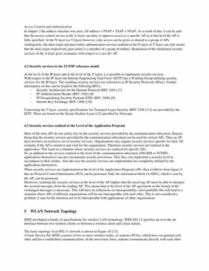
Fig. 11. BSS operating in infrastructure mode. The Extended Service Set (ESS) shown in Figure 12 consists of a series of overlapping BSSs (each containing an AP) connected together by means of a Distribution System (DS). Although the DS could be any type of network, it is almost invariably an Ethernet LAN. Mobile nodes can roam between APs and seamless campus-wide coverage is possible.
Station A2
Station A1
Station A3
AP
Wired network
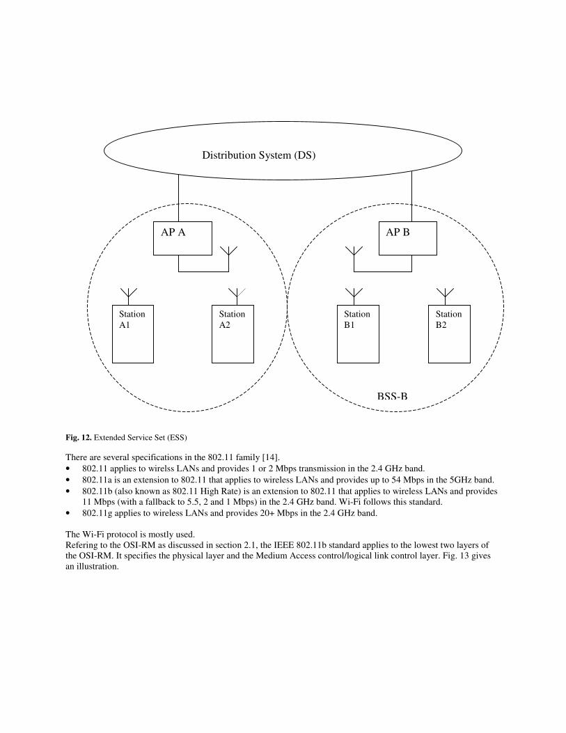
Fig. 12. Extended Service Set (ESS) There are several specifications in the 802.11 family [14]. • 802.11 applies to wirelss LANs and provides 1 or 2 Mbps transmission in the 2.4 GHz band. • 802.11a is an extension to 802.11 that applies to wireless LANs and provides up to 54 Mbps in the 5GHz band. • 802.11b (also known as 802.11 High Rate) is an extension to 802.11 that applies to wireless LANs and provides
11 Mbps (with a fallback to 5.5, 2 and 1 Mbps) in the 2.4 GHz band. Wi-Fi follows this standard. • 802.11g applies to wireless LANs and provides 20+ Mbps in the 2.4 GHz band. The Wi-Fi protocol is mostly used. Refering to the OSI-RM as discussed in section 2.1, the IEEE 802.11b standard applies to the lowest two layers of the OSI-RM. It specifies the physical layer and the Medium Access control/logical link control layer. Fig. 13 gives an illustration.
BSS-A
Station A1
Station A2
Station B1
Station B2
AP B
Distribution System (DS)
AP A
BSS-B
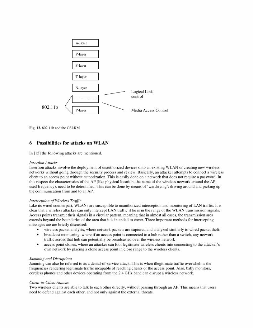
Fig. 13. 802.11b and the OSI-RM 6 Possibilities for attacks on WLAN In [15] the following attacks are mentioned. Insertion Attacks Insertion attacks involve the deployment of unauthorized devices onto an existing WLAN or creating new wireless networks without going through the security process and review. Basically, an attacker attempts to connect a wireless client to an access point without authorization. This is easily done on a network that does not require a password. In this respect the characteristics of the AP (like physical location, the name of the wireless network around the AP, used frequency), need to be determined. This can be done by means of ‘wardriving’: driving around and picking up the communication from and to an AP. Interception of Wireless Traffic Like its wired counterpart, WLANs are susceptible to unauthorized interception and monitoring of LAN traffic. It is clear that a wireless attacker can only intercept LAN traffic if he is in the range of the WLAN transmission signals. Access points transmit their signals in a circular pattern, meaning that in almost all cases, the transmission area extends beyond the boundaries of the area that it is intended to cover. Three important methods for intercepting messages are are briefly discussed:
• wireless packet analysis, where network packets are captured and analyzed similarly to wired packet theft; • broadcast monitoring, where if an access point is connected to a hub rather than a switch, any network
traffic across that hub can potentially be broadcasted over the wireless network • access point clones, where an attacker can fool legitimate wireless clients into connecting to the attacker’s
own network by placing a clone access point in close range to the wireless clients. Jamming and Disruptions Jamming can also be referred to as a denial-of-service attack. This is when illegitimate traffic overwhelms the frequencies rendering legitimate traffic incapable of reaching clients or the access point. Also, baby monitors, cordless phones and other devices operating from the 2.4 GHz band can disrupt a wireless network. Client-to-Client Attacks Two wireless clients are able to talk to each other directly, without passing through an AP. This means that users need to defend against each other, and not only against the external threats.
A-layer
P-layer
S-layer
T-layer
N-layer
P-layer
Logical Link control
Media Access Control 802.11b

Brute Force Attacks against Access Point Passwords A single key or password used by an AP is typically shared among all connecting wireless clients. A brute force dictionary attack attempts to compromise this key by testing every password possible. When the password is finally guessed, then the intruder is granted access to the AP. Encryption Attacks Attacks on the confidentiality and integrity of data transmitted. Misconfigurations In order to emphasize fast deployment and ease of use, many APs are shipped with a default configuration that is insecure. The administrator must understand wireless security risks before properly configuring each unit. Otherwise these APs will remain at risk for attack. 7 Security features WEP (Wired equivalent privacy) is 802.11’s optional encryption standard implemented in the MAC layer [16]. The principal goal of WEP is to defend the confidentiality of data from eavesdroppers. Another objective is to guard against surreptitious modification of data (integrity). An ancillary intention of WEP is to provide access control to the WLAN infrastructure [17]. WEP is a symmetric algorithm: both the sender and the receiver have the same key. Encryption takes place using a key of 64 or 128 bits. Effectively, the key length is only 40 (or 104) bits as a 24 bits initialization vector (IV) is used. The sender sends the IV in the clear to the receiver. The follwing figures 14 and 15 give a schematic representation how WEP is used to protect the WLAN communication [17]. Fig. 14. WEP protecting data at the sender’s side
Key (40 bits or 104 bits)
ICV
IV||ciphertext
ciphertext frame || ICV
key stream
IV (24 bits)
frame
RC4 PRNG ||
|| ||
CRC-32 calculation
plaintext =

Fig. 15. Decrypting and verifying the integrity of data at the receiver’s side First, WEP computes the ICV by performing a 32-bit cyclical redundancy check (CRC-32) of the frame and appends the vector to the original frame, resulting in the plaintext. Then, the frame plus ICV is encrypted via the RC4 Pseudo Random Number Generator algorithm. More specifically, the output of the RC4 PRNG is a long bitstream also called ‘keystream’. This keystream is a function of the 40-bit (or 104-bit) secret key (which is shared between all authorized stations in the WLAN) and a 24-bit initialization vector (IV). The ciphertext is produced by exoring the plaintext with the output of the RC4 PRNG. The ciphertext is sent over the radio link together with the IV. In most cases the sending station uses different IVs for each frame to be sent. The receiver performs the same procedure described above, but in reverse, to retrieve the original message frame. Specifically, the ciphertext is decrypted using a duplicated key stream to recover the plaintext. The recipient then validates the received ICV by computing a CRC-32 over the received frame and comparing it to the received ICV. Thus only frames with a valid checksum will be accepted by the receiver. So WEP is aimed to protect the confidentiality and integrity of messages. The following critical remarks can be made [17, 18]. Key management WEP is a symmetrical algorithm. In order to be able to use the WEP algorithm, the sender and receiver need to have the same key. In general, all stations in the range of an AP have the same key. This makes the security level of the communication between two stations dependent on all the other stations. It is clear that the key length is unsufficient: a 40-bit key is relatively easy to compromise via a brute-force attack, even with modest computing resources. A longer key of 128 bits (104-bit key + 24 bits IV) makes brute-force attacks much more difficult. However, alternative attacks are possible that do not require a brute-force strategy as indicated in the following items.
frame
key stream
ICV’ ICV
Key (40 or 104 bits)
IV (24 bits)
Extract ciphertext
Extract IV
|| RC4 PRNG
IV||ciphertext Extract frame
Extract ICV
CRC-32 calculation
ICV = ICV’ ?
If ICV = ICV’ then accept frame else reject frame
ciphertext plaintext

Passive Attack to Decrypt Traffic As mentioned, the IV is a 24-bit field intended to randomize part of the key. This means that an 802.11b AP transmitting at 11 Mbps can exhaust all IV combinations within 5 hours, as shown in equation 2. (For this attack it is assumed that the 40-bit or 104-bit key is shared by all stations on a WLAN.) The access point, which constantly sends 1500 byte packets at 11 Mbps, will exhaust the space of IVs after: 224 packets * 1500 bytes * 8 bits / 11*106 � 18,300 seconds � 5 hrs (2) While 802.11b APs generate a theoretical maximum of 11 Mbps, its observed rates are usually much less due to overhead and packet collisions, which can increase the amount of time before an IV is reused. However, packets are usually not at the Ethernet maximum of 1500 bytes, which reduces the IV reuse. In any event, this small space of IVs guarantees that a key stream will be reused in less than one-half of one day. The importance of this relatively small time is that an attacker can collect two ciphertext packets that are encrypted with the same key stream. By XORing two packets that use the same IV, the attacker obtains the XOR of the two plaintext messages. The resulting XOR can be used to infer data about the contents of the two messages. IP traffic is often very predictable and includes a lot of redundancy. This redundancy can be used to eliminate many possibilities for the contents of messages. Further educated guesses about the contents of one or both of the messages can be used to statistically reduce the space of possible messages, and in some cases it is possible to determine the exact contents. When such statistical analysis is inconclusive based on only two messages, the attacker can look for more collisions of the same IV. With only a small factor in the amount of time necessary, it is possible to recover a modest number of messages encrypted with the same key stream, and the success rate of statistical analysis grows quickly. Once it is possible to recover the entire plaintext for one of the messages, the plaintext for all other messages with the same IV follows directly. A variation to this attack is a threat where a host sends traffic from outside the WLAN to the AP. As he knows the plaintext and can tap the ciphertext, he can – by XORing plaintext and ciphertext – recover the crucial key stream. Active Attack to Insert Traffic The problems from the attack mentioned above can be worsened. As is mentioned already, an attacker can generate the key stream if he knows the precise plaintext and corresponding ciphertext. With this knowledge, the attacker can build correctly encrypted packets by constructing a message, calculating its CRC-32, and executing an XOR operation with the newly-discovered key stream. This ciphertext packet can be sent to the AP or mobile station to deceive it into thinking that it is a valid packet. A minor modification to this attack can make it much more pernicious. Even if the attacker has not attained complete knowledge of the packet, he can alter selected bits of the frame and successfully adjust the encrypted ICV to obtain a correct encrypted version of the modified packet. This is a lethal attack of the packet’s integrity, since all the attacker requires is partial knowledge of the packet’s contents to perform selective modification. Active Attack from Both Ends The previous attack can be extended further to decrypt arbitrary traffic. In this case, the attacker makes a guess not about the contents, but rather the headers of a packet. This information is usually quite easy to obtain or guess; in particular, all that is necessary to guess is the destination IP address. Armed with this knowledge, the attacker can flip appropriate bits to transform the destination IP address to send the packet to a machine he controls, somewhere in the Internet, and transmit it using a rogue mobile station. Most wireless installations have Internet connectivity; the packet will be successfully decrypted by the access point and forwarded unencrypted through appropriate gateways and routers to the attacker’s machine, revealing the plaintext. If a guess can be made about the TCP headers of the packet, it may even be possible to change the destination port on the packet to be port 80 (generally indicating World Wide Web service), which will allow it to be forwarded through most firewalls. Table-Based Attack The small space of potential IVs can allow the threat to construct a decryption table. Once the plaintext of a packet is realized, an attacker can compute the key stream produced by the IV utilized. Accordingly, this key stram can be
used to decrypt all other packets employing the same IV. Eventually, the threat can generate a table of IVs and corresponding key streams. Then the black hat can decrypt any and all packets sent over the wireless link, regardless of their IVs. Because the table can contain up to 224 (over 16 million) values, and each entry is a maximum of 1500 bytes, the table will be no larger than 24 GB. Thus, it is conceivable that a committed attacker can accumulate enough data to build a full decryption “dictionary”. While this would be an arduous undertaking, the motivation is that once the table is formed, it is possible to immediately decrypt every subsequent ciphertext with little effort. Worse yet, this table can be distributed to other black hats. The flaw herin lies in the 24-bit IV; if the IV is expanded in a future version of WEP, constructing such a dictionary would be exponentially more laborious. No end-to-end security As the WEP algorithm is implemented at the level of the MAC-layer, it does not provide end-to-end security. 8 Improvements in the field of WLAN security Despite the flaws, WEP is better than nothing and WEP should be enabled as a minimum level of security. Many people have taken to the streets to discover wireless LANs in neighbourhoods, business areas and colleges using protocol analyzers (wardriving). Most of the people are capable of detecting wireless LANs where WEP is not in use and then use a laptop to gain access to resources located on the associated network [16]. By activating WEP, however, you significantly minimize this from happening, especially with home or small business networks. WEP does a good job of keeping most people out, at least those that are honest. However there are true hackers around who can exploit the weaknesses of WEP and access WEP-enabled networks, especially those with high utilization [16]. So in order to prevent sophisticated attacks it is not OK to rely on WEP. In this respect other techniques are envisaged. Below options are discussed in order to improve the security level of WLANs [19]. 8.1 Virtual Private Networks Virtual Private Network technology (VPN) has been used to secure communications among remote locations via the Internet since the 1990s. A familiar and already widely used technology in the enterprise, it can readily be extended to Wi-Fi WLAN segments on existing wired networks. Although VPNs were originially developed to provide point-to-point encryption for long Internet connections between remote users and their corporate networks, they have recently been deployed in conjunction with Wi-Fi WLANs. When a WLAN client uses a VPN tunnel, communications data remains encrypted until it reaches the VPN gateway, which sits behind the wireless AP. Thus, intruders are effectively blocked from intercepting all network communications. Since the VPN encrypts the entire link from the PC to the VPN gateway in the heart of the corporate network, the wireless network segment between the PC and the AP is also encrypted. This is why VPNs have been recommended to help secure Wi-Fi. While VPNs are generally considered an enterprise solution, integrated products that offer VPN pass-through connections, firewalls and routers are available to accommodate telecommuters who work from home. Although they provide excellent security, VPNs are not self-managing. User credentials and, often, VPN software must be distributed to each client. However, when properly installed, VPNs extend the high level of security they provide on wired networks to WLANs. In fact, some Wi-Fi vendors themselves have utilized VPNs in networks to secure their own internal Wi-Fi networks. 8.2 IEEE 802.1X

Where VPN represents an excellent extension of a proven wired security technology to wireless networks, 802.1X represents a different approach to wireless security. Like VPNs, 802.1X was originally designed for wired networks. Approved in August 2001, it leverages the success of RADIUS (Remote Authentication Dial-In User Service) authentication servers to provide a higher level of security for WLAN users. Since its adoption by the IEEE, it has received widespread industry support. Also known as port-based network access control, 802.1X uses the Extensible Authentication Protocol (EAP) and RADIUS to authenticate clients and distribute keys. EAP provides an infrastructure that allows users to authenticate to a central authentication server. When the server accepts proof of the client’s identity, keying material is sent to both the client and the APs with which the authentication server enjoys a previously established “trusted relationship”. This relationship and the use of “mutual authentication” – in which the clients and the server prove their identities to each other – ensures that the APs that are on the network are the ones that are supposed to be there and protects clients from communicating with rogue APs. 802.1X and EAP also ensure that new encryption keys are generated and distributed frequently. This frequent distribution is known as “dynamic key” distribution, an essential element in a good security solution. By minimizing the time period in which any one encryption key is used, 802.1X and EAP reduce the time in which data can be collected to deduce the key. It effectively foils an eavesdropper by dramatically shrinking the size of the data set that can be collected to break an encryption key. 8.3 IEEE 802.11i Task Group i within IEEE 802.11, is developing a new standard for WLAN security. The proposed 802.11i standard is designed to embrace the authentication scheme of 802.1X and EAP while adding enhanced security features, including a new encryption scheme and dynamic key distribution. Not only does it fix WEP, it takes WLAN security to a higher level. The proposed specification uses the Temporal Key Integrity Protocol (TKIP) to produce a 128-bit “temporal key” that allows different stations to use different keys to encrypt data. TKIP introduces a sophisticated key generation function, which encrypts every data packet sent over the air with its own unique encryption key. Consequently, TKIP greatly increases the complexity and difficulty of decoding the keys. Intruders simply are not allowed enough time to collect sufficient data to decipher the key. 802.11i also endorses the Advanced Encryption Standard (AES) as a replacement for WEP encryption thus making it far more difficult to decipher than WEP. AES, however, is not readily compatible with today’s Wi-Fi CERTIFIED WLAN devices. It requires new chipsets, which, for WLAN customers, means new investments in wireless devices. Those looking to build new WLANs will find it attractive. Those with previously installed wireless networks must justify whether AES security is worth the cost of replacing equipment. 8.4 Wi-Fi Protected Access (WPA) As the adoption of the 802.11i standard will take some time, the Wi-Fi Alliance is addressing the need for an immediate, software-upgradeable security solution. Wi-Fi Protected Access (WPA) is a specification of standards-based, interoperable security enhancements that strongly increase the level of encryption and authentication for existing and future wireless LAN systems. WPA is derived from the upcoming IEEE 802.11i standard and will be forward compatible with it. WPA addresses the vulnerabilitites of WEP encryption and adds user authentication. Thus, WPA will provide wireless LAN users with a high level of assurance that their data will remain protected and that only authorized network users can access the network. Significantly, it is designed as a software upgrade to Wi-Fi=CERTIFIED devices, requiring no additional hardware.
WPA includes 802.1X and TKIP technology. 9 Conclusions Network security concentrates on protecting the exchange of information between two or more computing entities. The link between two computer systems can be secured by means of security services. Two principal implementations for realizing these security services can be discerned:
• implementation of security services in communication subsystems (OSI-RM, TCP/IP reference model); • implementing security services at the level of the application program itself.
Comparing these two possibilities, we can say that security services in a communication subsystem can provide a good basis for protecting the link between computer systems. However this will most probably be insufficient if an application is vital for a company. If applications are vital for a company, the company in question wants to be completely in control of the vital application. From security viewpoint, this will most probably lead to implementing security mechanisms at the level of the application itself. With respect to wireless computer networks, WEP is a weak security protocol. Relatively easy attacks are possible on the WEP algorithm thus enabling attacks harming the confidentiality and integrity of the data exchanged. Solutions are discussed (VPN, IEEE 802.1X, WPA and IEEE 802.1i) leading to a stronger protection of the data exchanged via the wireless network. References [1] Open Systems Interconnection Reference Model, Part 1: Basic Reference Model, ISO 7498-1 (CCITT X.200). Melbourne 1988 [2] Halsall, F., Data Communications, Computer Networks and OSI, 2nd edition, ISBN 0-201-18244-0. [3] Tanenbaum, A.S., Computer Networks, Third Edition, Prentice Hall, 1996 [4] Piscitello, D.M. and A.L. Chapin: Open Systems Networking: TCP/IP and OSI, Reading, MA: Addison-Wesley, 1993 [5] Open Systems Interconnection Reference Model, Part 2: Security Architecture, ISO DIS 7498-2, July 19, 1988. [6] Common Criteria for Information Technology Security Evaluation, part 1: Introduction and general model, August 1999, version 2.1 [7] Security Architecture for the Internet Protocol (RFC 2401) http://www.ietf.org/rfc/rfc2401.txt [8] IP Authentication Header (RFC 2402) http://www.ietf.org/rfc/rfc2402.txt [9] IP Encapsulating Security Payload (ESP) (RFC 2406) http://www.ietf.org/rfc/rfc2406.txt [10] Internet Key Exchange (RFC 2409) http://www.ietf.org/rfc/rfc2409.txt [11] RFC 2246, http://www.ietf.org/rfc/rfc2246.txt [12] Secure Sockets Layer, http://wp.netscape.com/eng/ssl3/ [13] Jim Zyren, Petrick, Al, IEEE 802.11 Tutorial, http://www.weca.net/OpenSection/pdf/IEEE_80211_Primer.pdf [14] http://www.webopedia.com/TERM/8/802_11.html

[15] Robert Starr, Wireless LAN Security, March 26, 2002, http://www.packetninja.ca/starrrt.html [16] Jim Geier, 802.11 WEP: Concepts and Vulnerability, http://www.80211-planet.com/tutorials/article.php/1368661 [17] Princy C. Mehta, Wired Equivalent Privacy Vulnerability, LevelOne Security Essentials Track, April 2001 http://ouah.kernsh.org/wirelessvuln.htm [18] Nikita Borisov, Ian Goldberg, David Wagner, Security of the WEP algorithm, http://www.isaac.cs.berkeley.edu/isaac/wep-faq.html [19] Wi-Fi Alliance, Securing Wi-Fi Wireless Networks with Today’s Technologies, February 6, http://www.wi-fi.org/OpenSection/pdf/Whitepaper_Wi-Fi_Networks2-6-03.pdf