security reliability low power integration
TRANSCRIPT

Power Matters.™
X+/-
D
EN
>> 17
A[17:0]
B[17:0]
SN-1[43:0]
C[43:0]
SHIFT17
SEL_CASC
SN[43:0]
OVFL
ADD_SUB
0
LUT4A
B
C
D
LUT_BYPEN
CLKRST
LO
RO
CIN
CO
D
EN
SL
SYNC_SR
FPGAs
SoC FPGAs
Design Tools
Design Hardware
Intel lectual Property
FPGA and SoC Product Catalog
S E C U R I T Y R E L I A B I L I T Y L O W P O W E R I N T E G R AT I O N

www.microsemi.com/fpga-soc
Providing industry-leading FPGAs and SoCs for
applications where security is vital, reliability is
non-negotiable and power matters.

3www.microsemi.com/fpga-soc
Whether you’re designing at the board or system level, Microsemi’s SoC FPGAs and low power FPGAs are your best choice. The unique, flash-based technology of Microsemi FPGAs, coupled with their history of reliability, sets them apart from traditional FPGAs.
Design for today’s rapidly growing markets of consumer and portable medical devices, or tomorrow’s environmentally friendly data centers, industrial controls and military and commercial aircraft. Only Microsemi can meet the power, size, cost and reliability targets that reduce time-to-market and enable long-term profitability.
Now, more than ever, power matters.
Table of Contents
SmartFusion®2
• SoC FPGA with 166 MHz ARM® Cortex™-M3, 150 K logic elements
• SERDEs, DDR, DSP processing, embedded NVM and SRAM
4
IGLOO®2 • Best-in-class integration, low power, reliability and security 5
SmartFusion • SoC FPGA with 100 MHz ARM Cortex-M3, 500 K system gates, analog processing 6
IGLOO/e • Lowest power FPGA with up to 3 M system gates 7
IGLOO nano • Lowest power FPGA with smallest package footprint 8
IGLOO PLUS • Lowest power FPGA with high I/O-to-logic ratio 9
ProASIC®3/E • Low power, high performance FPGA with up to 3 M system gates 10
ProASIC3 nano • Low power, high performance FPGA with smallest pack-age footprint 11
ProASIC3L • Low power, high performance FPGA with Flash*Freeze 12
Fusion • Mixed signal FPGA 13
Military SmartFusion, Fusion and ProASIC3/EL
• Mixed signal integration down to –55ºC• Reprogrammable digital logic, configurable analog,
embedded flash memory • Unprecedented low power consumption across the
full military temperature range• High-density fine-pitch ball grid packaging• High Performance And Easy In-System Programming
14
Military ProASICPLUS®• Industry’s first military screened flash FPGA• Full processing to MIL-STD-883 Class B• Established heritage on commercial and military aircraft
15
IGLOO and ProASIC Family I/O Selector
• I/O counts 16
FPGA Packages • Package dimensions 18
Design Tools • Design software for Microsemi FPGAs and SoC FPGAs 20
Development Kits • Starter, evaluation and development kits 21
Programmers • FlashPro3 and Silicon Sculptor 3 programmers 25
Intellectual Property Cores • Microsemi Intellectual Property (IP) products designed and optimized for use with Microsemi FPGAs 26
Please refer to www.microsemi.com/fpga-soc and appropriate product datasheets for the latest device information, valid ordering codes and more information regarding previous generations of flash FPGAs.

4 www.microsemi.com/products/fpga-soc/soc-fpga/smartfusion2
Sm
art
Fu
sio
n2
Type FCS325 VF256 VF400 FCV484 VQ144 FG484 FG676 FG896 FC1152
Pitch (mm) 0.5 0.8 0.8 0.8 0.5 1.0 1.0 1.0 1.0
Length x Width (mm) 11x11 14x14 17x17 19x19 20x20 23x23 27x27 31x31 35x35
Device I/O Lanes I/O Lanes I/O Lanes I/O Lanes I/O Lanes I/O Lanes I/O Lanes I/O Lanes I/O Lanes
M2S005 (S) — — — — 171 — — 83¹ — 209 — — — — — — —
M2S010 (S/T/TS) — — 148¹ 2¹ 195 4 — — 75¹ — 233 4 — — — — — —
M2S025 (S/T/TS) 180 2 148¹ 2¹ 207 4 — — — — 267 4 — — — — — —
M2S050 (S/T/TS) 200 2 — — 207 4 — — — — 267 4 — — 377 8 — —
M2S090 (S/T/TS)² 200¹ 4¹ — — — — — — — — 267 4 425 4 — — — —
M2S100 (S/T/TS) — — — — — — 273¹ 4¹ — — — — — — — — 574 8
M2S150 (S/T/TS) — — — — — — 273¹ 4¹ — — — — — — — — 574 16
Notes:1. Preliminary.2. 090 FCS325 is 11x13.5 package dimension.
SmartFusion2The next-generation System-on-Chip FPGA
Microsemi’s next-generation SmartFusion2 System-on-Chip (SoC) FPGAs are the only devices that address fundamental requirements for advanced security, high reliability and low power in critical industrial, military, aviation, communications and medical applications. SmartFusion2 integrates an inherently reliable flash-based FPGA fabric, a 166 MHz ARM Cortex-M3 processor, advanced security processing accelerators, DSP blocks, SRAM, eNVM and industry-required high-performance communication interfaces all on a single chip.
SmartFusion2 Devices
I/Os Per Package
SmartFusion2 Devices M2S005 M2S010 M2S025 M2S050 M2S090 M2S100 M2S150
Logic/DSP
Maximum Logic Elements (4LUT + DFF)1 6,060 12,084 27,696 56,340 86,316 99,512 146,124
Math Blocks (18x18) 11 22 34 72 84 160 240
Fabric Interface Controllers (FICs) 1 2
PLLs and CCCs 2 6 8
Security AES256, SHA256, RNG AES256, SHA256, RNG, ECC, PUF
Microcontroller Subsystem (MSS)
Cortex-M3 + Instruction Cache Yes
eNVM (K Bytes) 128 256 512
eSRAM (K Bytes) 64
eSRAM (K Bytes) Non SECDED 80
CAN, 10/100/1000 Ethernet, HS USB 1 each
Multi-Mode UART, SPI, I2C, Timer 2 each
Fabric Memory
LSRAM 18 K Blocks 10 21 31 69 109 160 236
uSRAM 1 K Blocks 11 22 34 72 112 160 240
Total RAM (K bits) 191 400 592 1314 2074 3040 4488
High Speed
DDR Controllers (count x width) 1x18 2x36 1x18 2x36
SERDES Lanes (T) 0 4 8 4 8 16
PCIe End Points 0 1 2 4
User I/O
MSIO (3.3 V) 115 123 157 139 309 292 292
MSIOD (2.5 V) 28 40 40 62 40 106 106
DDRIO (2.5 V) 66 70 70 176 76 176 176
Total User I/O 209 233 267 377 425 574 574
Notes:1. Total logic may vary based on utilization of DSP and memories in your design. Please see the SmartFusion2 Fabric UG for details.2. Feature availablility is package dependent.

5www.microsemi.com/products/fpga-soc/fpga/igloo2-fpga
IGL
OO
2
• Highest number of 5G transceivers1
• Highest number of GPIO1
• Highest number of PCI compliant 3.3 V I/O1
• Only FPGA with hardened memory subsystem
• Only non-volatile and instant-on mainstream FPGA
• 10x lower static power with the same performance
• 1 mW in Flash*Freeze mode
• Only FPGA with SEU immune fabric and mainstream features
• Extended temperature support (up to 125ºC Tj)
• Built-in state-of-the-art design security for all devices
• Root-of-trust
• Easy-to-use
IGLOO2The FPGA with high level of integration at the lowest total system cost
The IGLOO2 FPGA family provides a 4-input look-up table (LUT) based fabric, 5G transceivers, high-speed general purpose I/O (GPIO), block RAM and digital signal processing (DSP) blocks in a differentiated, cost- and power-optimized architecture. This next-generation IGLOO2 FPGA architecture offers up to 5x more logic density and 3x more fabric performance than its predecessors and combines a non-volatile flash-based fabric with the highest number of GPIO, 5G serialization/deserialization (SERDES) interfaces and PCI Express® (PCIe®) endpoints when compared to other products in its class.
IGLOO2 Devices Features M2GL005 M2GL010 M2GL025 M2GL050 M2GL090 M2GL100 M2GL150
Logic/DSP
Maximum Logic Elements (4LUT + DFF)1 6,060 12,084 27,696 56,340 86,316 99,512 146,124
Math Blocks (18x18) 11 22 34 72 84 160 240
PLLs and CCCs 2 6 8
SPI/HPDMA/PDMA 1 each
Fabric Interface Controllers (FICs) 1 2
Security AES256, SHA256, RNG AES256, SHA256, RNG, ECC, PUF
Memory
eNVM (K Bytes) 128 256 512
LSRAM 18 K Blocks 10 21 31 69 109 160 236
uSRAM 1 K Blocks 11 22 34 72 112 160 240
eSRAM (K Bytes) 64
Total RAM (K bits) 703 912 1104 1826 2586 3552 5000
High Speed
DDR Controllers 1x18 2x36 1x18 2x36
SERDES Lanes (T) 0 4 8 4 8 16
PCIe End Points 0 1 2 4
User I/Os
MSIO (3.3 V) 115 123 157 139 309 292 292
MSIOD (2.5 V) 28 40 40 62 40 106 106
DDRIO (2.5 V) 66 70 70 176 76 176 176
Total User I/O 209 233 267 377 425 574 574
Note:1. Total logic may vary based on utilization of DSP and memories in your design. Please see the IGLOO2 Fabric UG for details. 2. Feature availablility is package dependent.
I/Os per PackageType FCS325 VF256 VF400 FCV484 VQ144 FG484 FG676 FG896 FC1152
Pitch (mm) 0.5 0.8 0.8 0.8 0.5 1.0 1.0 1.0 1.0
Length x Width (mm) 11x11 14x14 17x17 19x19 20x20 23x23 27x27 31x31 35x35
Device I/O Lanes I/O Lanes I/O Lanes I/O Lanes I/O Lanes I/O Lanes I/O Lanes I/O Lanes I/O Lanes
M2GL005 (S) — — — — 171 — — — 83¹ — 209 — — — — — — —
M2GL010 (S/T/TS) — — 148¹ 2¹ 195 4 — — 75¹ — 233 4 — — — — — —
M2GL025 (S/T/TS) 180 2 148¹ 2¹ 207 4 — — — — 267 4 — — — — — —
M2GL050 (S/T/TS) 200 2 — — 207 4 — — — — 267 4 — — 377 8 — —
M2GL090 (S/T/TS)² 200¹ 4¹ — — — — — — — — 267 4 425 4 — — — —
M2GL100 (S/T/TS) — — — — — — 273¹ 4¹ — — — — — — — — 574 8
M2GL150 (S/T/TS) — — — — — — 273¹ 4¹ — — — — — — — — 574 16
Note:1 Preliminary. 2. 090 FCS325 is 11x13.5 package dimension.

6 www.microsemi.com/products/fpga-soc/soc-fpga/smartfusion
Sm
art
Fu
sio
n
SmartFusionThe customizable SoC device
SmartFusion SoCs are the only devices that integrate FPGA fabric, an ARM Cortex-M3 processor and programmable analog, offering full customization, IP protection and ease-of-use. Based on Microsemi’s proprietary flash process, SmartFusion SoCs are ideal for hardware and embedded designers who need a true system-on-chip that gives more flexibility than traditional fixed-function microcontrollers without the excessive cost of soft processor cores on traditional FPGAs.
• Available in commercial, industrial and military grades
• Hard 100 MHz 32-bit ARM Cortex-M3 CPU
• Multi-layer AHB communications matrix with up to 16 Gbps throughput
• 10/100 Ethernet MAC
• Two peripherals of each type: SPI, I2C, UART and 32-bit timers
• Up to 512 KB flash and 64 KB SRAM
• External memory controller (EMC)
• 8-channel DMA controller
• Integrated analog-to-digital converters (ADCs) and digital- to-analog converters (DACs) with 1 percent accuracy
• On-chip voltage, current and temperature monitors
• Up to ten 15 ns high-speed comparators
• Analog compute engine (ACE) offloads CPU from analog processing
• Up to 35 analog I/Os and 169 digital GPIOs
SmartFusion Devices
Notes:1. Not available on A2F500 for the PQ208 package.2. Two PLLs are available in CS288 and FG484 (one PLL in FG256 and PQ208).3. These functions share I/O pins and may not all be available at the same time. See the “Analog Front-End Overview” section in the SmartFusion Programmable Analog User’s Guide for details.4. Available on FG484 only. PQ208, FG256 and CS288 packages offer the same programmable analog capabilities as A2F200.
Notes:1. There are no LVTTL capable direct inputs available on A2F060 devices.2. These pins are shared between direct analog inputs to the ADCs and voltage/current/temperature monitors.3. EMC is not available on the A2F500 PQ208 and A2F060 TQ144 package.
Package I/Os: MSS + FPGA I/Os
SmartFusion Devices A2F060 A2F200 A2F500
FPGA Fabric
System Gates 60,000 200,000 500,000
Tiles (D-flip-flops) 1,536 4,608 11,520
RAM Blocks (4,608 bits) 8 8 24
Microcontroller Subsystem (MSS)
Flash (Kbytes) 128 256 512
SRAM (Kbytes) 16 64 64
Cortex-M3 with Memory Protection Unit (MPU) Yes Yes Yes
10/100 Ethernet MAC No Yes Yes
External Memory Controller (EMC) 26-bit address, 16-bit data1 26-bit address, 16-bit data 26-bit address, 16-bit data1
DMA 8 Ch 8 Ch 8 Ch
I2C 2 2 2
SPI 1 1 1
16550 UART 2 2 2
32-Bit Timer 2 2 2
PLL 1 1 22
32 KHz Low Power Oscillator 1 1 1
100 MHz On-Chip RC Oscillator 1 1 1
Main Oscillator (32 KHz to 20 MHz) 1 1 1
Programmable Analog
ADCs (8-/10-/12-bit SAR) 1 2 34
DACs (12-bit sigma-delta) 1 2 34
Signal Conditioning Blocks (SCBs) 1 4 54
Comparators3 2 8 104
Current Monitors3 1 4 54
Temperature Monitors3 1 4 54
Bipolar High Voltage Monitors3 2 8 104
DeviceA2F0601 A2F2002 A2F5002
TQ144 CS288 FG256 PQ208 CS288 FG256 FG484 PQ208 CS288 FG256 FG484
Direct Analog Inputs 11 11 11 8 8 8 8 8 8 8 12
Shared Analog Inputs1 4 4 4 16 16 16 16 16 16 16 20
Total Analog Input 15 15 15 24 24 24 24 24 24 24 32
Total Analog Output 1 1 1 1 2 2 2 1 2 2 3
MSS I/Os2 212 282 262 22 31 25 41 22 31 25 41
FPGA I/Os 33 68 66 66 78 66 94 663 78 66 128
Total I/Os 70 112 108 113 135 117 161 113 135 117 204

7www.microsemi.com/products/fpga-soc/fpga/igloo-e
IGL
OO
/e
• Ultra low power FPGAs
• Flash*Freeze technology for lowest power consumption
• 1.2 V core and I/O voltage
• Instant-on
• AES-protected in-system programming (ISP)
• User nonvolatile FlashROM
IGLOO/e
Notes:1. AES is not available for Cortex-M1 IGLOO devices.2. AGL060 in CS121 does not support the PLL.3. Six chip (main) and twelve quadrant global networks are available for AGL060 devices and above. 4. The M1AGL250 device does not support this package.5. Device/package support TBD.
IGLOO/e Devices
Notes:1. The M1AGL250 device does not support QN132 or CS196 packages. 2. Each used differential pair reduces the number of single-ended I/Os available by two. 3. When the Flash*Freeze pin is used to directly enable Flash*Freeze mode and not used as a regular I/O, the number of single-ended user I/Os available is reduced by one.4. Device/package support TBD.5. FG256 and FG484 are footprint-compatible packages.
I/Os Per PackageIGLOO Devices AGL030 AGL060 AGL125 AGL250 AGL400 AGL600 AGL1000 AGLE600 AGLE3000
ARM-Enabled IGLOO Devices M1AGL250 M1AGL600 M1AGL1000 M1AGLE3000
I/O PackageSingle-Ended
I/O
Single-Ended
I/O
Single-Ended
I/O
Single-Ended
I/O2
Differen-tial I/O Pairs
Single-Ended
I/O2
Differen-tial I/O Pairs
Single-Ended
I/O2
Differen-tial I/O Pairs
Single-Ended
I/O2
Differen-tial I/O Pairs
Single-Ended
I/O2
Differen-tial I/O Pairs
Single-Ended
I/O2
Differen-tial I/O Pairs
QN48 34 — — — — — — — — — — — — — —
QN68 49 — — — — — — — — — — — — — —
UC81 66 — — — — — — — — — — — — — —
CS81 66 — — 60 7 — — — — — — — — — —
CS121 — 96 96 — — — — — — — — — — — —
VQ100 77 71 71 68 13 — — — — — — — — — —
QN132 81 80 84 871,4 191,4 — — — — — — — — — —
CS196 — — 133 1431 351 143 35 — — — — — — — —
FG144 — 967 97 97 24 97 25 97 25 97 25 — — — —
FG2565 — — — — — 178 38 177 43 177 44 165 79 — —
CS281 — — — — — — — 215 53 215 53 — — — —
FG4845 — — — — — 194 38 235 60 300 74 270 135 341 168
FG896 — — — — — — — — — — — — — 620 310
The ultra low power programmable solution
The IGLOO family of reprogrammable, full-featured flash FPGAs is designed to meet the demanding power, area and cost requirements of today’s portable electronics. Based on nonvolatile flash technology, the 1.2 V to 1.5 V operating voltage family offers the industry’s lowest power consumption—as low as 5 µW. The IGLOO family supports up to 3,000,000 system gates with up to 504 Kbits of true dual-port SRAM, up to 6 embedded PLLs and up to 620 user I/Os. Low power applications that require 32-bit processing can use the ARM Cortex-M1 processor without license fee or royalties in M1 IGLOO devices. Developed specifically for implementation in FPGAs, Cortex-M1 devices offer an optimal balance between performance and size to minimize power consumption.
IGLOO Devices AGL030 AGL060 AGL125 AGL250 AGL400 AGL600 AGL1000 AGLE600 AGLE3000
ARM-Enabled IGLOO Devices2 M1AGL250 M1AGL600 M1AGL1000 M1AGLE3000
System Gates 30,000 60,000 125,000 250,000 400,000 600,000 1,000,000 600,000 3,000,000
Typical Equivalent Macrocells 256 512 1,024 2,048 — — — — —
VersaTiles (D-flip-flops) 768 1,536 3,072 6,144 9,216 13,824 24,576 13,824 75,264
Flash*Freeze Mode (typical, µW) 5 10 16 24 32 36 53 49 137
RAM (1,024 bits) — 18 36 36 54 108 144 108 504
RAM Blocks (4,608 bits) — 4 8 8 12 24 32 24 112
FlashROM Kbits (1,024 bits) 1 1 1 1 1 1 1 1 1
AES-Protected ISP1 — Yes Yes Yes Yes Yes Yes Yes Yes
Integrated PLLs with CCC2 — 1 1 1 1 1 1 6 6
VersaNet Globals3 6 18 18 18 18 18 18 18 18
I/O Banks 2 2 2 4 4 4 4 8 8
Maximum User I/Os 81 96 133 143 194 235 300 270 620
Package Pins UC CS
QN
VQ FG
UC81CS81
QN48QN68QN132 VQ100
CS1213
QN132
VQ100 FG1446
CS196QN132
VQ100 FG144
CS81 CS1964
QN1324,5
VQ100FG144
CS196
FG144FG256FG484
CS281
FG144FG256 FG484
CS281
FG144 FG256 FG484
FG256 FG484
FG484FG896

8 www.microsemi.com/products/fpga-soc/fpga/igloo-nano
IGL
OO
na
no
• Ultra low power in Flash*Freeze mode, as low as 2 µW
• Small footprint packages from 14×14 mm to 3×3 mm
• Enhanced commercial temperature
• 1.2 V to 1.5 V single voltage operation
• Enhanced I/O features
• Embedded SRAM and nonvolatile memory (NVM)
• ISP and security
IGLOO nano
IGLOO nano Devices
I/Os Per PackageIGLOO nano Devices AGLN010 AGLN020 AGLN060 AGLN125 AGLN250
Known Good Die 34 52 71 71 68
UC36 23 — — — —
QN48 34 — — — —
QN68 — 49 — — —
UC81 — 52 — — —
CS81 — 52 60 60 60
VQ100 — — 71 71 68
The industry’s lowest power, smallest-size solution
IGLOO nano products offer ground breaking possibilities in power, size, lead-times, operating temperature and cost. Available in logic densities from 10,000 to 250,000 gates, the 1.2 V to 1.5 V IGLOO nano devices have been designed for high-volume applications where power and size are key decision criteria. IGLOO nano devices are perfect ASIC or ASSP replacements, yet retain the historical FPGA advantages of flexibility and quick time-to-market in low power and small footprint profiles.
Notes:1. AGLN030 and smaller devices do not support this feature.2. AGLN060, AGLN125 and AGLN250 in the CS81 package do not support PLLs.3. For higher densities and support of additional features, refer to the IGLOO and IGLOOe datasheets and FPGA fabric user’s guides.
Note:1. When the Flash*Freeze pin is used to directly enable Flash*Freeze mode and not used as a regular I/O, the number of single-ended user I/Os available is reduced by one.2. For nano devices, the VQ100 package is offered in both leaded and RoHS-compliant versions. All other packages are RoHS-compliant only.
IGLOO nano Devices AGLN010 AGLN020 AGLN060 AGLN125 AGLN250
System Gates 10,000 20,000 60,000 125,000 250,000
Typical Equivalent Macrocells 86 172 512 1,024 2,048
VersaTiles (D-flip-flops) 260 520 1,536 3,072 6,144
Flash*Freeze Mode (typical, µW) 2 4 10 16 24
RAM Kbits1 (1,024 bits)1 — — 18 36 36
4,608-Bit Blocks1 — — 4 8 8
FlashROM Kbits (1,024 bits) 1 1 1 1 1
AES-Protected ISP1 — — Yes Yes Yes
Integrated PLL in CCCs1,2 — — 1 1 1
VersaNet Globals 4 4 18 18 18
I/O Banks 2 3 2 2 4
Maximum User I/Os (packaged device) 34 52 71 71 68
Maximum User I/Os (known good die) 34 52 71 71 68
Package Pins UC CS QN VQ
UC36
QN48
UC81CS81QN68
CS81
VQ100
CS81
VQ100
CS81
VQ100

9www.microsemi.com/products/fpga-soc/fpga/igloo-plus
IGL
OO
PL
US
IGLOO PLUS
IGLOO PLUS Devices
I/Os Per Package
IGLOO PLUS Devices AGLP030 AGLP060 AGLP125
System Gates 30,000 60,000 125,000
Typical Equivalent Macrocells 256 512 1,024
VersaTiles (D-flip-flops) 792 1,584 3,120
Flash*Freeze Mode (typical, µW) 5 10 16
RAM (1,024 bits) — 18 36
4,608-Bit Blocks — 4 8
FlashROM Kbits (1,024 bits) 1 1 1
AES-Protected ISP — Yes Yes
Integrated PLL in CCCs1 — 1 1
VersaNet Globals2 6 18 18
I/O Banks 4 4 4
Maximum User I/Os (packaged device) 120 157 212
Package Pins CS VQ
CS201, CS289VQ128
CS201, CS289VQ176
CS281, CS289
IGLOO PLUS Devices AGLP030 AGLP060 AGLP125
I/O Package Single-Ended I/O Single-Ended I/O Single-Ended I/O
CS201 120 157 —
CS281 — — 212
CS289 120 157 212
VQ128 101 — —
VQ176 — 137 —
The low power FPGA with enhanced I/O capabilities
IGLOO PLUS products deliver unrivaled low power and I/O features in a feature-rich programmable device, offering up to 64 percent more I/Os than the award-winning IGLOO products and supporting independent Schmitt trigger inputs, hot-swapping and Flash*Freeze bus hold. Ranging from 30,000 to 125,000 gates, the 1.2 V to 1.5 V IGLOO PLUS devices have been optimized to meet the needs of I/O-intensive, power-conscious applications that require exceptional features.
• I/O-optimized FPGA
• Ultra low power in Flash*Freeze mode, as low as 5 µW
• Small footprint and low-cost packages
• Reprogrammable flash technology
• 1.2 V to 1.5 V single voltage operation
• Embedded SRAM NVM
• AES-protected ISP
Notes:1. AGLP060 in CS201 does not support the PLL.2. Six chip (main) and twelve quadrant global networks are available for AGLP060 and AGLP125.
Note:* When the Flash*Freeze pin is used to directly enable Flash*Freeze mode and not used as a regular I/O, the number of single-ended user I/Os available is reduced by one.

10
Pro
AS
IC3
/E
ProASIC3/E
I/Os Per Package
The low power, low-cost FPGA solution
The ProASIC3 series of flash FPGAs offers a breakthrough in power, price, performance, density and features for today’s most demanding high-volume applications. ProASIC3 devices support the ARM Cortex-M1 processor, offering the benefits of programmability and time-to-market at low cost. ProASIC3 devices are based on nonvolatile flash technology and support 30,000 to 3,000,000 gates and up to 620 high-performance I/Os. For automotive applications, selected ProASIC3 devices are qualified to the AEC-Q100 and are available with AEC T1 screening and PPAP documentation.
ProASIC3 Devices A3P030 A3P060 A3P125 A3P250 A3P400 A3P600 A3P1000 A3PE600 A3PE1500 A3PE3000
ARM Cortex-M1 Devices
M1A3P250* M1A3P400 M1A3P600 M1A3P1000 M1A3PE1500 M1A3PE3000
I/O TypeSingle-Ended
I/O
Single-Ended
I/O
Single-Ended
I/O
Single-Ended
I/O
Differen-tial I/O Pairs
Single-Ended
I/O
Differen-tial I/O Pairs
Single-Ended
I/O
Differen-tial I/O Pairs
Single-Ended
I/O
Differen-tial I/O Pairs
Single-Ended
I/O
Differen-tial I/O Pairs
Single-Ended
I/O
Differen-tial I/O Pairs
Single-Ended
I/O
Differen-tial I/O Pairs
QN48 34 — — — — — — — — — — — — — — — —
QN68 49 — — — — — — — — — — — — — — — —
QN132 81 80 84 87 19 — — — — — — — — — — — —
CS121 — 96 — — — — — — — — — — — — — — —
VQ100 77 71 71 68 13 — — — — — — — — — — — —
TQ144 — 91 100 — — — — — — — — — — — — — —
PQ208 — — 133 151 34 151 34 154 35 154 35 147 65 147 65 147 65
FG144 — 96 97 97 24 97 25 97 25 97 25 — — — — — —
FG256 — — — 157 38 178 38 177 43 177 44 165 79 — — — —
FG324 — — — — — — — — — — — — — — — 221 110
FG484 — — — — — 194 38 235 60 300 74 270 135 280 139 341 168
FG676 — — — — — — — — — — — — — 444 222 — —
FG896 — — — — — — — — — — — — — — — 620 310
Notes:1. AES is not available for Cortex-M1 ProASIC3 devices.2. Available as automotive “T” grade3. The M1A3P250 device does not support this package.4. Six chip (main) and three quadrant global networks are available for A3P060 and above.5. The PQ208 package supports six CCCs and two PLLs.
Note:1. M1A3P250 does not support the FG256 and QN132 packages.2. When using voltage-referenced I/O standards, one I/O pin should be assigned as a voltage-reference pin (VREF) per minibank (group of O/Os).3. “G” indicates RoHS-compliant packages. Refer to the “ProASIC3E Ordering Information” on page 3 for the location of the “G” in the part number.
ProASIC3/E Devices A3P030 A3P060 A3P125 A3P250 A3P400 A3P600 A3P1000 A3PE600 A3PE1500 A3PE3000
ARM Cortex-M1 Devices M1A3P250 M1A3P400 M1A3P600 M1A3P1000 M1A3PE1500 M1A3PE3000
System Gates 30,000 60,000 125,000 250,000 400,000 600,000 1,000,000 600,000 1,500,000 3,000,000
Typical Equivalent Macrocells 256 512 1,024 2,048 — — — — — —
VersaTiles (D-flip-flops) 768 1,536 3,072 6,144 9,216 13,824 24,576 13,824 38,400 75,264
RAM (1,024 bits) — 18 36 36 54 108 144 108 270 504
4,608-Bit Blocks — 4 8 8 12 24 32 24 60 112
FlashROM Kbits (1,024 bits) 1 1 1 1 1 1 1 1 1 1
AES-Protected ISP1 — Yes Yes Yes Yes Yes Yes Yes Yes Yes
Integrated PLL in CCCs — 1 1 1 1 1 1 6 6 6
VersaNet Globals4 6 18 18 18 18 18 18 18 18 18
I/O Banks 2 2 2 4 4 4 4 8 8 8
Maximum User I/Os 81 96 133 157 194 235 300 270 444 620
Package Pins QFN
CS VQ TQ PQ FG
QN48QN68QN132
VQ100
QN132
CS121VQ1002
TQ144
FG1442
QN1322
VQ1002
TQ144PQ208FG1442
QN1322, 3
VQ1002
PQ208FG1442
FG2562, 3
PQ208 FG144FG256FG484
PQ208 FG144FG256FG484
PQ208 FG1442
FG2562
FG4842
PQ2085 FG256FG484
PQ2085 FG484FG676
PQ2085
FG324FG484FG896
• Low power
• Nonvolatile, reprogrammable
• Instant-on
• Configuration memory error immune
• Advanced I/O standards
• Secure ISP
ProASIC3/E Devices
www.microsemi.com/products/fpga-soc/fpga/proasic3-e

11www.microsemi.com/products/fpga-soc/fpga/proasic3-nano
Pro
AS
IC3
na
no
Note:“G” indicates RoHS-compliant packages. Refer to “ProASIC3 nano Ordering Information” on page 3 of the datasheet for the location of the “G” in the part number. For nano devices, the VQ100 package is offered in both leaded and RoHS-compliant versions. All other packages are RoHS-compliant only.
ProASIC3 nanoThe lowest-cost solution with enhanced I/O capabilities
Microsemi’s innovative ProASIC3 nano devices bring a new level of value and flexibility to high-volume markets. When measured against the typical project metrics of performance, cost, flexibility and time-to-market, ProASIC3 nano devices provide an attractive alternative to ASICs and ASSPs in fast moving or highly competitive markets. Customer-driven total system cost reduction was a key design criteria for the ProASIC3 nano program. Reduced device cost, availability of known good die, a single-chip implementation and a broad selection of small footprint packages all contribute to lower total system costs.
• 1.5 V core for low power
• 350 MHz system performance
• Configuration memory error immune
• Enhanced commercial temperature
• Enhanced I/O features
• ISP and security
I/Os Per Package
ProASIC3 nano DevicesProASIC3 nano Devices A3PN010 A3PN020 A3PN060 A3PN125 A3PN250
System Gates 10,000 20,000 60,000 125,000 250,000
Typical Equivalent Macrocells 86 172 512 1,024 2,048
VersaTiles (D-flip-flops) 260 520 1,536 3,072 6,144
RAM1 (1,024 bits) — — 18 36 36
4,608-Bit Blocks1 — — 4 8 8
FlashROM Kbits (1,024 bits) 1 1 1 1 1
AES-Protected ISP1 — — Yes Yes Yes
Integrated PLL in CCCs1 — — 1 1 1
VersaNet Globals 4 4 18 18 18
I/O Banks 2 3 2 2 4
Maximum User I/Os (packaged device) 34 49 71 71 68
Known Good Die User I/Os 34 52 71 71 68
Package Pin QN VQ
QN48 QN68VQ100 VQ100 VQ100
ProASIC3 nano Devices A3PN010 A3PN020 A3PN060 A3PN125 A3PN250
Known Good Die 34 52 71 71 68
QN48 34 — — — —
QN68 — 49 — — —
VQ100 — — 71 71 68
Notes:1. A3PN030 and smaller devices do not support this feature.2. For higher densities and support of additional features, refer to the ProASIC3 and ProASIC3E datasheets and FPGA fabric user’s guides.
12 www.microsemi.com/products/fpga-soc/fpga/proasic3l
Pro
AS
IC3
L
Notes:1. Refer to the Cortex-M1 product brief for more information. 2. AES is not available for Cortex-M1 ProASIC3L devices.3. For the A3PE3000L, the PQ208 package has six CCCs and two PLLs.
Notes:1. When considering migrating your design to a lower- or higher-density device, refer to the packaging section of the datasheet to ensure you are complying with design and board migration requirements.2. For A3P250L devices, the maximum number of LVPECL pairs in east and west banks cannot exceed 15.3. ARM Cortex-M1 support is TBD on this device.4. Each used differential I/O pair reduces the number of single-ended I/Os available by two.5. FG256 and FG484 are footprint-compatible packages.6. “G” indicates RoHS-compliant packages. Refer to “ProASIC3L Ordering Information” on page 3 of the datasheet for the location of the “G” in the part number.7. For A3PE3000L devices, the usage of certain I/O standards is limited as follows: – SSTL3(I) and (II): up to 40 I/Os per north or south bank – LVPECL / GTL+ 3.3 V / GTL 3.3 V: up to 48 I/Os per north or south bank – SSTL2(I) and (II) / GTL+ 2.5 V/ GTL 2.5 V: up to 72 I/Os per north or south bank8. When the Flash*Freeze pin is used to directly enable Flash*Freeze mode and not as a regular I/O, the number of single-ended user I/Os available is reduced by one.
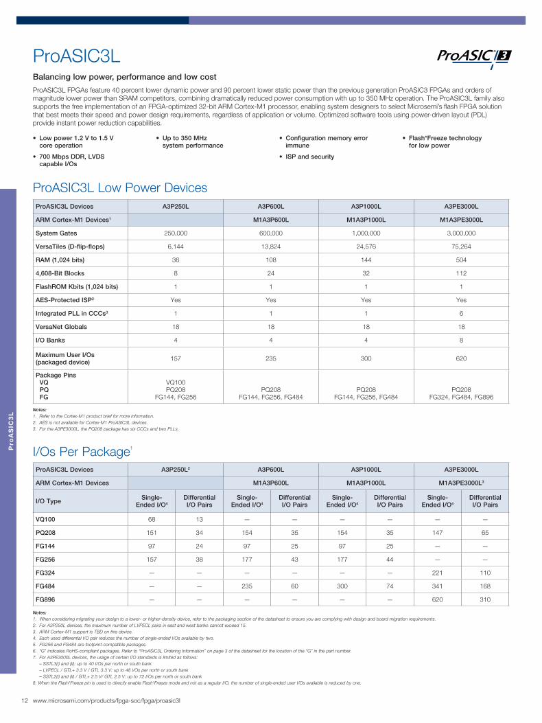
ProASIC3LBalancing low power, performance and low cost
ProASIC3L FPGAs feature 40 percent lower dynamic power and 90 percent lower static power than the previous generation ProASIC3 FPGAs and orders of magnitude lower power than SRAM competitors, combining dramatically reduced power consumption with up to 350 MHz operation. The ProASIC3L family also supports the free implementation of an FPGA-optimized 32-bit ARM Cortex-M1 processor, enabling system designers to select Microsemi’s flash FPGA solution that best meets their speed and power design requirements, regardless of application or volume. Optimized software tools using power-driven layout (PDL) provide instant power reduction capabilities.
I/Os Per Package1
ProASIC3L Low Power DevicesProASIC3L Devices A3P250L A3P600L A3P1000L A3PE3000L
ARM Cortex-M1 Devices1 M1A3P600L M1A3P1000L M1A3PE3000L
System Gates 250,000 600,000 1,000,000 3,000,000
VersaTiles (D-flip-flops) 6,144 13,824 24,576 75,264
RAM (1,024 bits) 36 108 144 504
4,608-Bit Blocks 8 24 32 112
FlashROM Kbits (1,024 bits) 1 1 1 1
AES-Protected ISP2 Yes Yes Yes Yes
Integrated PLL in CCCs3 1 1 1 6
VersaNet Globals 18 18 18 18
I/O Banks 4 4 4 8
Maximum User I/Os (packaged device) 157 235 300 620
Package Pins VQ PQ FG
VQ100PQ208
FG144, FG256PQ208
FG144, FG256, FG484PQ208
FG144, FG256, FG484PQ208
FG324, FG484, FG896
ProASIC3L Devices A3P250L2 A3P600L A3P1000L A3PE3000L
ARM Cortex-M1 Devices M1A3P600L M1A3P1000L M1A3PE3000L3
I/O Type Single-Ended I/O4
DifferentialI/O Pairs
Single-Ended I/O4
DifferentialI/O Pairs
Single-Ended I/O4
DifferentialI/O Pairs
Single-Ended I/O4
DifferentialI/O Pairs
VQ100 68 13 — — — — — —
PQ208 151 34 154 35 154 35 147 65
FG144 97 24 97 25 97 25 — —
FG256 157 38 177 43 177 44 — —
FG324 — — — — — — 221 110
FG484 — — 235 60 300 74 341 168
FG896 — — — — — — 620 310
• Low power 1.2 V to 1.5 V core operation
• 700 Mbps DDR, LVDS capable I/Os
• Up to 350 MHz system performance
• Configuration memory error immune
• ISP and security
• Flash*Freeze technology for low power

13www.microsemi.com/products/fpga-soc/fpga/fusion
Fu
sio
n
• Integrated A/D converter (ADC) with 8-, 10- and 12-bit resolution and 30 scalable analog input channels
• ADC accuracy better than 1 percent
• On-chip voltage, current and temperature monitors
• In-system configurable analog supports a wide variety of applications
• Up to 1 MB of user flash memory
• Extensive clocking resources
• Analog PLLs
• 1 percent RC oscillator
• Crystal oscillator circuit
• Real-time counter (RTC)
• Instant-on
• Configuration memory error immune
• Advanced I/O standards
• User nonvolatile FlashROM
Notes:1. Refer to the Cortex-M1 product brief for more information.2. Pigeon Point devices only offered in FG484 and FG256 packages.3. MicroBlade devices only offered in FG256 package.
Notes:1. Pigeon Point devices only offered in FG484 and FG256 packages.2. MicroBlade devices only offered in FG256 package.3. Fusion devices in the same package are pin compatible with the exception of the PQ208 package (AFS250 and AFS600).
Fusion
Package I/Os: Single-/Double-Ended (Analog)Fusion Devices AFS090 AFS250 AFS600 AFS1500
ARM Cortex-M1 Devices M1AFS250 M1AFS600 M1AFS1500
Pigeon Point Devices P1AFS6001 P1AFS15001
MicroBlade Devices U1AFS2502 U1AFS6002 U1AFS5002
QN108 37/9 (16) — — —
QN180 60/16 (20) 65/15 (24) — —
PQ2083 — 93/26 (24) 95/46 (40) —
FG256 75/22 (20) 114/37 (24) 119/58 (40) 119/58 (40)
FG484 — — 172/86 (40) 223/109 (40)
FG676 — — — 252/126 (40)
Fusion Devices
The world’s first mixed signal FPGA
Fusion FPGAs integrate configurable analog, large flash memory blocks, comprehensive clock generation and management circuitry and high-performance, flash-based programmable logic in a monolithic device. The Fusion architecture can be used with soft microcontroller cores, such as the performance-optimized ARM Cortex-M1, 8051s or Microsemi’s own CoreABC, the smallest soft microcontroller for FPGAs.
Fusion Devices AFS090 AFS250 AFS600 AFS1500
ARM Cortex-M11 Devices M1AFS250 M1AFS600 M1AFS1500
Pigeon Point Devices P1AFS6002 P1AFS15002
MicroBlade Devices U1AFS250 U1AFS6003 U1AFS500
General Information
System Gates 90,000 250,000 600,000 1,500,000
Tiles (D–flip–flops) 2,304 6,144 13,824 38,400
AES-protected ISP Yes Yes Yes Yes
PLLs 1 1 2 2
Globals 18 18 18 18
Memory
Flash Memory Blocks (2 Mbits) 1 1 2 4
Total Flash Memory Bits 2,000,000 2,000,000 4,000,000 8,000,000
FlashROM Bits 1,024 1,024 1,024 1,024
RAM Blocks (4,608 bits) 6 8 24 60
RAM (Kbits) 27 36 108 270
Analog and I/Os
Analog Quads 5 6 10 10
Analog Input Channels 15 18 30 30
Gate Driver Outputs 5 6 10 10
I/O Banks (+ JTAG) 4 4 5 5
Maximum Digital I/Os 75 114 172 252
Analog I/Os 20 24 40 40

14 www.microsemi.com/fpga-soc
Mil
ita
ry S
ma
rtF
us
ion
, F
us
ion
an
d P
roA
SIC
3/E
L
Military SmartFusion, Fusion and ProASIC3/ELLow power FPGAs for military applications
Building on the successful heritage of the Military ProASICPLUS family, Military FPGAs offer higher performance, greater density and more memory, while at the same time offering high reliability combined with compact single-chip logic integration, Instant-on operation and reprogrammability. Fusion and SmartFusion Military FPGA’s offer integrated configurable analog and can use built-in soft ARM Cortex-M1 or hard 50 MHz ARM Cortex M3.
• Supports single-voltage system operation
• Up to 3,000,000 system gates
• Instant-on level 0 support
• Secure ISP using on-chip 128-bit advanced encryption
• Single-event upset (SEU) immune
• Standard (AES) decryption via JTAG
Military SmartFusion, Fusion and ProASIC3 DevicesProASIC3/EL Devices A3P250 A3PE600L A3P1000 A3PE3000L AFS600 AFS1500 A2F060 A2F500
ARM Cortex-M1 Devices1 M1A3P1000 M1A3PE3000L M1A2F500 M1AFS1500 Hard 32-Bit
ARM Cortex-M3Hard 32-Bit
ARM Cortex-M3
System Gates 250,000 600,000 1,000,000 3,000,000 600,000 1,500,000 60,000 500,000
VersaTiles (D-flip-flops) 6,144 13,824 24,576 75,264 13,824 38,400 1,536 11,520
AES-Protected ISP1 Yes Yes Yes Yes Yes Yes Yes Yes
RAM (1,024 bits) 36 108 144 504 108 270 16 64
RAM Blocks (4,608 bits) 8 24 32 112 24 60 8 24
Maximum User I/Os 68 270 300 620 212 263 108 204
Digital I/Os 68 270 154 620 172 223 92 169
Analog I/Os — — — — 40 40 16 35
PLL 1 6 1 6 2 2 1 2
ADCs (8-,10-,12-bit SAR) — — — — 1 1 1 3
Packages VQ PQ FG
VQ100
FG484PQ208
FG144, FG256, FG484
PQ208FG324, FG484,
FG896FG256, FG484 FG256, FG484 FG256 FG256, FG484
Notes:1. Refer to ARM Cortex-M1 product brief for more information.2. AES is not available for ARM-enabled devices.

15www.microsemi.com/fpga-soc
Milita
ry P
roA
SIC
PL
US
Military ProASICPLUS
Reprogrammable, nonvolatile military FPGAs
Military ProASICPLUS is the industry’s first nonvolatile, reprogrammable FPGA with testing covering the full military temperature range (–55ºC to 125ºC), with available MIL-STD-883 Class B screening. The flash-based reprogrammable interconnect used in Microsemi’s ProASICPLUS FPGAs has been proven to be immune to configuration changes caused by atmospheric neutrons.
Military ProASICPLUS DevicesMilitary ProASICPLUS Devices APA300 APA600 APA1000
Maximum System Gates 300,000 600,000 1,000,000
Tiles (registers) 8,192 21,504 56,320
RAM Kbits (1,024 bits) 72 126 198
RAM Blocks (256x9) 32 56 88
LVPECL 2 2 2
PLL 2 2 2
Global Networks 4 4 4
Maximum Clocks 32 56 88
Maximum User I/Os 290 454 712
JTAG ISP Yes Yes Yes
PCI Yes Yes Yes
Package Pins PQ PB PG FG CF CQ CG
456144, 256208, 352
456256, 484, 676
208, 352208, 352
624
208456
896, 1152
208, 352624

1716 www.microsemi.com/fpga-soc www.microsemi.com/fpga-soc
3x3 UC36 0.40
4x4 UC81 0.40
5x5 CS81 0.50
6x6 CS121 0.50
6x6 QN48 0.40
8x8 CS196 0.50
8x8 QN68 0.40
8x8 QN132 0.50
8x8 CS201 0.50
10x10 QN108 0.50
10x10 QN180 0.50
10x10 CS281 0.50
11x11 CS288 0.50
13x13 FG144 1.00
14x14 CS289 0.80
14x14 VQ100 0.50
14x14 VQ128 0.40
17x17 FG256 1.00
19x19 FG324 1.00
20x20 TQ144 0.50
20x20 VQ176 0.40
23x23 FG484 1.00
27x27 FG676 1.00
28x28 PQ208 0.50
31x31 FG896 1.00
32.5x32.5 CG624 1.27
29.21x29.21 CQ208 0.50
48x48 CQ352 0.50
23
34
52
52
49
66
66
34
49
81
120
120
77
101
60
96
80
157
112
96
157
71
108
91
137
60
96
133
84
212
97
212
71
100
133
60/7
143/35
87/19
65/15 (24)
97/24
68/13
114/37 (24) 157/38
93/26 (24) 151/34
158
248
143/35
97/25
178/38
194/38
151/34
215/53
97/25
119/58 (40) 177/43
172/86 (40) 235/60
95/46 (40) 154/35
440
158
248
215/53
97/25
177/44
300/74
154/35
440
158
248
165/79
270/135
147/65
119/58 (40)
223/109(40) 280/139
252/126(40) 444/222
147/65
221/110
341/168
147/65
620/310
Size (mm) Name Pitch (mm)
IGLOO/e
IGLOO nano2
IGLOO PLUS
ProASIC3/E
ProASIC3 nano2
ProASIC3L
Military ProASIC3/EL
Military ProASICPLUS
AGLN010
A3PN010
AGLN020
A3PN020
AGL030
AGLP030
A3P030
AGL060
AGLN060
AGLP060
A3P060
A3PN060
AGL125
AGLN125
AGLP125
A3P125
A3PN125
AFS250
AGL250
AGLN250
A3P250
A3PN250
A3P250L
A3P250
APA300
AGL400
A3P400
AFS600
AFS600
AGL600
A3P600
A3P600L
APA600
AGL1000
A3P1000
A3P1000L
A3P1000
APA1000
AGLE600
A3PE600
A3PE600L
AFS1500
AFS1500
A3PE1500
AGLE3000
A3PE3000
A3PE3000L
A3PE3000L
IGL
OO
an
d P
roA
SIC
Fa
mil
y I
/O S
ele
cto
r
IGLOO and ProASIC Family I/O Selector1
Notes: 1. # / # structure shows single-ended/double-ended I/Os. Fusion and Ext. Temp. Fusion I/O counts are in italics. Value in parentheses for Fusion is analog I/Os. SmartFusion values are total analog, MSS and FPGA I/Os. 2. IGLOO nano and ProASIC3 nano devices do not have differential I/Os.3. Please refer to the SoC Products Group’s website at www.microsemi.com/soc and appropriate product datasheets for the latest device information and valid ordering codes.
IGL
OO
an
d P
roA
SIC
Fa
mily
I/O S
ele
cto
r
Go to www.microsemi.com/fpga-soc for information regarding previous generations of flash and antifuse FPGAs.

18 www.microsemi.com/fpga-soc
FP
GA
Pa
ck
ag
es
FPGA Packages
CS121f IGLOO ProASIC3ps 6x6 mmh 0.90 mmp 0.50 mm
CS81f IGLOO IGLOO nanops 5x5 mmh 0.80 mmp 0.50 mm
UC81f IGLOO IGLOO nanops 4x4 mmh 0.80 mmp 0.40 mm
UC36f IGLOO nanops 3x3 mmh 0.80 mmp 0.40 mm
FG896f SmartFusion2 IGLOO2 IGLOOe1
ProASIC3E1
ProASIC3L1
Military ProASIC3/EL1
ps 31x31 mmh 2.23 mmp 1.00 mm
FG144f IGLOO1
ProASIC31
ProASIC3L1
Military ProASIC3/EL1
ps 13x13 mmh 1.45 mmp 1.00 mm
FC1152f IGLOO2ps 35x35 mmh 2.62 mmp 1.00 mm
FG256f SmartFusion Fusion1, 3, 4
IGLOO1
IGLOOe ProASIC31, 2
ProASIC3E2
ProASIC3L1
ps 17x17 mmh 1.60 mmp 1.00 mm
FG676f IGLOO2 ProASIC3E1 Fusion1
ps 27x27 mmh 2.23 mmp 1.00 mm
FG484f SmartFusion2 SmartFusion Fusion1, 3
IGLOO2 IGLOO1
IGLOOe1
ProASIC31, 2
ProASIC3E1, 2
ProASIC3L1
Military ProASIC3/EL1
ps 23x23 mmh 2.23 mmp 1.00 mm
FG324f ProASIC3E1
ProASIC3L1
ps 19x19 mmh 1.63 mmp 1.00 mm
VF400f SmartFusion2 IGLOO2ps 17x17 mmh 1.41 mmp 0.80 mm
CS196f IGLOOps 8x8 mmh 1.11 mmp 0.50 mm
CS201f IGLOO PLUSps 8x8 mmh 0.89 mmp 0.50 mm
CS281f IGLOO1 IGLOO PLUSps 10x10 mmh 1.05 mmp 0.50 mm
CS288f SmartFusionps 11x11 mmh 1.05 mmp 0.50 mm
CS289f IGLOO PLUSps 14x14 mmh 1.20 mmp 0.80 mm
QN68f IGLOO IGLOO nano ProASIC3 ProASIC3 nanops 8x8 mm h 0.90 mmp 0.40 mm
QN48f IGLOO IGLOO nano ProASIC3 ProASIC3 nanops 6x6 mm h 0.90 mmp 0.40 mm
QN108f Fusionps 8x8 mm h 0.75 mmp 0.50 mm
QN132f IGLOO ProASIC3ps 8x8 mm h 0.75 mmp 0.50 mm
QN180f Fusionps 10x10 mm h 0.75 mmp 0.50 mm
Key: f – family bs – package body size excluding leads p s – overall package dimensions including package leads h – package thickness p – pin pitch / ball pitch
Notes:1 Includes Cortex-M1 devices.2 FG256 and FG484 are footprint-compatible for ProASIC3 and ProASIC3E.3 Pigeon Point devices are only offered in FG484 and FG256.4 MicroBlade devices are only offered in FG256.

19www.microsemi.com/fpga-soc
FP
GA
Pa
ck
ag
es
Refer to the Package Mechanical Drawings document located at www.microsemi.com/document-portal/doc_download/131095-package-mechanical-drawings for more information concerning package dimensions.
TQ144f ProASIC3bs 20x20 mmps 22x22 mm h 1.40 mmp 0.50 mm
VQ100f IGLOO1
IGLOO nano ProASIC31
ProASIC3 nano ProASIC3L Military ProASIC3/EL1
bs 14x14 mmps 16x16 mmh 1.00 mmp 0.50 mm
PQ208f SmartFusion Fusion1
ProASIC31
ProASIC3E1
ProASIC3L1
Military ProASIC3/EL1
bs 28x28 mmps 30.6x30.6 mmh 3.40 mmp 0.50 mm
VQ128f IGLOO PLUSbs 14x14 mmps 16x16 mmh 1.00 mmp 0.40 mm
VQ176f IGLOO PLUSbs 20x20 mmps 22x22 mmh 1.00 mmp 0.40 mm
CQ352f Military ProASICPLUS
ps 48x48 mmh 2.67 mmp 0.50 mm
CQ208f Military ProASICPLUS
ps 29.21x29.21 mmh 2.67 mmp 0.50 mm
CG624f Military ProASICPLUS
ps 32.5x32.5 mmh 4.94 mmp 1.27 mm

20 www.microsemi.com/fpga-soc/design-resources/design-software/libero-soc
Libero® System on Chip (SoC) and Libero Integrated Design Environment (IDE) Microsemi are comprehensive software toolsets for designing with Microsemi FPGAs. Different versions of Libero support different families (see Product Family support for details).
• Libero SoC supports Microsemi’s IGLOO2, SmartFusion2, SmartFusion, IGLOO, ProASIC3 and Fusion families managing the entire design flow from design entry, synthesis and simulation, through place-and-route, timing and power analysis, with enhanced integration of the embedded design flow. Libero SoC also includes a new System Builder design approach for correct by construction SoC FPGA configuration.
• Libero IDE software supports designing with Microsemi Rad-Tolerant FPGAs, Antifuse FPGAs and Legacy & Discontinued Flash FPGAs and managing the entire design flow from design entry, synthesis and simulation, through place-and-route, timing and power analysis.
Libero SoC provides a new SoC design flow, specifically targeted to simplify the design of our newest flash FPGAs. Standalone tools such as Silicon Sculptor, FlashPro and Synphony Model Compiler AE are not changing and will continue to include support for all silicon devices.
Two types of Libero licenses are available. Libero Gold Free licenses covers the majority of mainstream FPGAs, while Libero Platinum supports the high end and advanced feature devices.
Libero SoC
System Builder
Program Device
RTL andConstraints
Firmware and Project Settings
ApplicationDevelopment
FPGAImplementation
Mic
ros
em
i D
es
ign
So
ftw
are
Design Software for Microsemi SoC FPGAs and FPGAs
Licensing Requirements
Product Family Device
License
Gold (FREE) Platinum/Standalone
SmartFusion2/IGLOO2
M2S005, M2S010, M2S025, M2S050, M2GL005, M2GL010, M2GL025, M2GL050 ✓ ✓M2S090, M2S100, M2S150, M2GL090, M2GL100, M2GL150All S (Security) devices require a Platinum License. ✓
SmartFusion, IGLOO, ProASIC3,Fusion and ProASICPLUS All Devices ✓ ✓
Licensing Features
License Features
Libero Gold Libero Platinum Libero Standalone
FREE Purchased Purchased
License Term 1 Year 1 Year 1 Year
Libero Design Software, including SmartDesign, IP Catalog and Place and Route ✓ ✓ ✓SoftConsole* ✓ ✓ ✓FlashPro Software* ✓ ✓ ✓IP Cores Bundle Gold IP Platinum IP Platinum IP
Synopsys Synplify Pro AE, ModelSim AE, Synopsys Identify AE* ✓ ✓ Not Included
* The following software is not supported on the Linux platforms: Viewdraw, FlashPro, SoftConsole, Firmware Catalog and Identify.
Embedded Design Support
Features
Microsemi Keil IAR Systems
SoftConsole Keil MDK Embedded Workbench®
Free Versions from Microsemi Free with Libero SoC 32 K Code Limited 32 K Code Limited
Available from Vendor N/A Full Version Full Version
Compiler GNU GCC RealView® C/C++ IAR ARM Compiler
Debugger GDB Debug µVision® Debugger C-SPY® Debugger
Instruction Set Simulator No µVision Simulator Yes
Debug Hardware FlashPro4 ULINK2® or ULINK-ME™ J-Link™ or J-Link Lite
Go to www.microsemi.com/fpga-soc/design-resources/design-software/libero-soc for system requirements.

21www.microsemi.com/products/fpga-soc/design-resources/dev-kits-boards
De
ve
lop
me
nt K
its
• Full-featured SmartFusion2 development platform
• Support for HS USB 2.0 OTG, CAN RS232, RS484, IEEE 1588 time stamping and Sync E capable triple speed Ethernet PHYs
• Access to SERDES high speed serial interfaces via PCI edge connector or high speed SMP connectors
• Bundled with FlashPro4 programmer, USB cables and PCIE edge card ribbon cable
• Free Libero SoC software license included
• Board features
- 50 K LE SmartFusion2 device
- 16x 5 Gbps SERDES, PCIe, XAUI/XGXS+ Native SERDES
- 16-bit, 1 MSPS, 8-channel Precision ADC
- 512 MB DDR3, 16 MB SDRAM, 8 MB SPI Flash memory
- JTAG Interface for programming and debug
- Embedded Trace Macro connector
- I2C, SPI, GPIO headers
- FMC connector for daughter card expansion
Ordering Codes Supported Devices Price
SF2-DEV-KIT M2S050T-1FGG896 $ 1,800
12 V PowerSupply Section
DC JackUSB Mini BConnector
(FTDI)
USB Micro ABConnector
RS485Header
ADC
ExternalFlash PCIe Edge Connector
DDR3Memory
TimeStamping
SMPConnectors
POE
SDRAM
SmartFusion2
RJ45 Connectorfor Ethernet
POE Connector
Marvell PHY
Reset Switch
ClockConditioning
SFPConnector
TimingChip Reset
ETMHeader
FP4Header
FMCHeader
RVIHeader
CAN1Connector
CAN2Connector
FTDIProgrammer
SPI Flash
MMUART1Connector
Power-OnSwitch
SmartFusion2 Development Kit
UserButton
ResetButton
64 MBLPDDR
16 MBSPI Flash
JTAG I/F
JP2 EthernetPHY
SmartFusion2M2S SOM
(System-On-Module)
BreadboardArea
Ethernet I/F
USBPower &USB UART I/F
LEDs
JP3
JP1
HS USBOTG
Interface
SmartFusion2 Starter Kit
Ordering Code Supported Device Price
SF2-STARTER-KIT-ES-2 M2S050T-FGG896ES $ 299
SF2-484-STARTER-KIT M2S010-FGG484 $299
• Cost-efficient development platform for SmartFusion2 SoC FPGA
• Supports industry-standard interfaces including Ethernet, USB, SPI, I2C and UART
• Preloaded with uClinux image to support Linux-based development environments
• Comes with FlashPro4 programmer, USB cables and USB WiFi module
• Free Libero SoC software license included
• Board features
- 50K LE or 10K LE SmartFusion2 device
- JTAG interface for programming and debug
- 10/100 Ethernet
- USB 2.0 On-The-Go
- 64 MB LPDDR, 16 MB SPI Flash memory
- 4 LEDs and 2 push-button switches
- On-module clocks
- Watchdog timer (WDT)
CurrentMeasurement
LPCrystals
On Board125 Mhz
12 V PowerSupply Input
On/OffSwitch
10/100/1000Ethernet
RJ45Connector
SERDESReference
Clock
MicroUSBOTG
LPDDR50 MhzOscillator
GPIOHeader
LEDs JTAG ProgrammingHeader
ResetSwitch
SW3SW4 SW2
SW5
IGLOO2x1 PCIe Edge
Connector
SW1
RVI/IAR DebugHeader
I2CHeader
ETM TraceDebug Header
SPIFlash
USB-UARTTerminal
Tx/RxSERDES SMA Pairs
IGLOO2 Evaluation Kit• Gives designers access to IGLOO2
FPGAs which offer leadership in I/O density, security, reliability and low power into mainstream applications
• Up to 150 K LE, 240 integrated DSP blocks, 16 channels of 5 Gbps SERDES and 4 Gen2 PCIe endpoints,
• Supports industry-standard interfaces including Gigabit Ethernet, USB 2.0 OTG, SPI, I2C and UART
• Free license for Microsemi’s Libero SoC software and comes preloaded with a PCIe control plane demo
• Can be powered through a 12 V power supply or the PCIe connector and includes a FlashPro4 programmer
• Board features
- IGLOO2 FPGA in the FG484 package (M2GL010T-FG484)
- JTAG/SPI programming interface
- Gigabit Ethernet PHY and RJ45 connector
- USB 2.0 OTG interface connector
- 1GB LPDDR, 64MB SPI Flash
- Headers for I2C, UART, SPI, GPIOs
- x1 Gen2 PCIe edge connector
- Tx/Rx/Clk SMP pairs
Ordering Code Supported Device Price
M2GL-EVAL-KIT M2GL010T-1FGG484 $ 399
22 www.microsemi.com/products/fpga-soc/design-resources/dev-kits-boards
De
ve
lop
me
nt
Kit
s
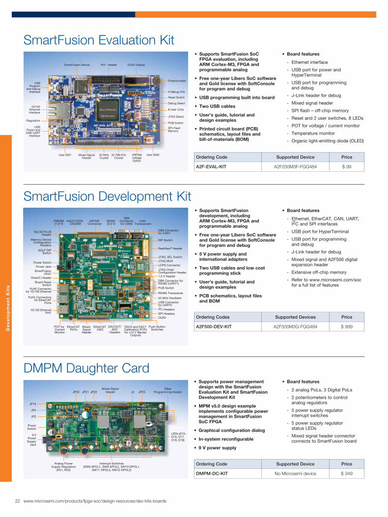
• Supports SmartFusion development, including ARM Cortex-M3, FPGA and programmable analog
• Free one-year Libero SoC software and Gold license with SoftConsole for program and debug
• 5 V power supply and international adapters
• Two USB cables and low cost programming stick
• User’s guide, tutorial and design examples
• PCB schematics, layout files and BOM
• Board features
- Ethernet, EtherCAT, CAN, UART, I2C and SPI interfaces
- USB port for HyperTerminal
- USB port for programming and debug
- J-Link header for debug
- Mixed signal and A2F500 digital expansion header
- Extensive off-chip memory
- Refer to www.microsemi.com/soc for a full list of features
Ordering Codes Supported Devices Price
A2F500-DEV-KIT A2F500M3G-FGG484 $ 999
DirectC Header
Board ResetSwitch
Power Jack
Memory DeviceConfiguration
Headers
AGLP DIPSwitch
AGLP125V5-CSG289
IGLOO PLUSHeader
10/100 EthernetPHY
RJ45 Connectorfor 10/100 Ethernet
Power Switch
DACOUT/ADC
Headers
RJ45 Connectorsfor EtherCAT
Ports
SmartFusioncSoC
DB9Connectorfor CAN0
SRAM (3.3 V)
CAN Transceivers
DB9 Connectorfor CAN1
A2F500 Connector
PSRAM(1.8 V)
LCPS Connector
DIP Switch
JTAG_SEL Switch
JTAG ChainConfiguration Header1.5 V Header
PUB Switch
RS485 Transceiver
DB9 Connector forRS485 (UART1)
50 MHz Oscillator
SPI HeadersI2C Headers
USB Connector for UART0
OLED
Push-Button Switches
RealView® Header
JTAG MUX
EtherCAT PHYs
DAC0 and DAC1Callibration POTsfor ±15 V Bipolar
Outputs
POT for CurrentMonitor
Mixed SignalHeader
EtherCAT ASIC
SmartFusion Development Kit
9 VPowerSupply
Jack
Analog PowerSupply Regulators
(RV1, RV2)
Interrupt Switches(SW8-APOL1, SW9-APOL2, SW10-DPOL1,
SW11-DPOL3, SW12-DPOL2)
PowerSwitch
JP3
JP19
JP2
JP20 J2Mixed Signal
Header JP23Zilker
Programming HeaderJP21 JP22
LEDs (D15, D16, D17, D18, D19)
DMPM Daughter Card• Supports power management
design with the SmartFusion Evaluation Kit and SmartFusion Development Kit
• MPM v5.0 design example implements configurable power management in SmartFusion SoC FPGA
• Graphical configuration dialog
• In-system reconfigurable
• 9 V power supply
• Board features
- 2 analog PoLs, 3 Digital PoLs
- 2 potentiometers to control analog regulators
- 5 power supply regulator interrupt switches
- 5 power supply regulator status LEDs
- Mixed signal header connector connects to SmartFusion board
Ordering Code Supported Device Price
DMPM-DC-KIT No Microsemi device $ 349
• Supports SmartFusion SoC FPGA evaluation, including ARM Cortex-M3, FPGA and programmable analog
• Free one-year Libero SoC software and Gold license with SoftConsole for program and debug
• USB programming built into board
• Two USB cables
• User’s guide, tutorial and design examples
• Printed circuit board (PCB) schematics, layout files and bill-of-materials (BOM)
• Board features
- Ethernet interface
- USB port for power and HyperTerminal
- USB port for programming and debug
- J-Link header for debug
- Mixed signal header
- SPI flash – off-chip memory
- Reset and 2 user switches, 8 LEDs
- POT for voltage / current monitor
- Temperature monitor
- Organic light-emitting diode (OLED)
Ordering Code Supported Device Price
A2F-EVAL-KIT A2F200M3F-FGG484 $ 99
10/100EthernetInterface
Regulators
USBProgram
and DebugInterface
SmartFusion Device
User SW2
USBPower andUSB-UART
Interface
Potentiometer
Reset Switch
5 Debug I/Os
8 User LEDs
Debug Select
JTAG Select
OLED DisplayRVI - Header
SPI-Flash Memory
PUB Switch
VRPSMVoltageOption
20 MHzCrystal
32.768 KHzCrystal
User SW1 Mixed SignalHeader
SmartFusion Evaluation Kit

23www.microsemi.com/products/fpga-soc/design-resources/dev-kits-boards
De
ve
lop
me
nt K
its
Ordering Code Supported Device Price
AGLN-NANO-KIT* AGLN250V2-VQG100 $ 99
• Supports basic IGLOO nano low power FPGA design, including Flash*Freeze mode
• Free one-year Libero SoC software and Gold license
• Low-cost programming stick (LCPS)
• Two USB cables
• Kit user’s guide, Libero SoC tutorial and design examples
• PCB schematics, layout files and BOM
• Board features
- All I/Os available for external connections
- Full current measurement capability of independent I/O banks and VCC
- USB connection for USB-to- serial (RS232) interface for HyperTerminal or power
- 20 MHz clock oscillator
- LEDs and switches for simple inputs and outputs
- Ability to switch VCORE from 1.2 V to 1.5 V
- RoHS compliant
20 MHzClock Oscillator
IGLOO nanoFPGA
I/O Test PinHeaders
USBInterface
5 V WallJack
Jumpersfor Voltage
Options
Jumperfor Battery
Option
4 Push-ButtonSwitches
LCPSConnector
Push-ButtonReset Switch
Flash*FreezeSwitch
Current MeasurementHeaders
8 User LEDs8 DIP Switches
Jumpers to Isolate User LEDs, Push-Button Switches, DIP Switches for I/O Test Pins
IGLOO nano Starter Kit
Note:* Replaces -Z version of the nano Starter Kit.
• Supports basic ProASIC3 FPGA design and LVDS I/O usage
• Free one-year Libero SoC software and Gold license
• FlashPro3 or FlashPro4 Programmer
• 9 V power supply and international adapters
• Kit user’s guide, Libero SoC tutorial and design examples
• PCB schematics, layout files and BOM
• Board features
- Eight I/O banks with variety of voltage options
- Oscillator for system clock or manual clock option
- LEDs and switches for simple inputs and outputs
- LCD display module
- Two CAT5E RJ45 connectors for high-speed LVDS communications
- All I/Os available for external connections
- Not RoHS compliant
Wall MountPower
Interboard ISP Connector
LCD DisplayModule
CAT5E RJ45Connectors
for LVDSCommunications
SMA forOptionalExternal
Oscillator
Removable Shunts to Isolate All I/Os for Prototyping
Removable Shunts to
Isolate All I/Os for Prototyping
Oscillator for System
Clock
Manual Clock Option
FlashPro3 ISP Connector
ProASIC3/E in PQ208 Package
4 Switches
Every PQ208 Pin Accessible for Prototyping
8 LEDs
Removable Shunts to IsolateAll I/Os for Prototyping
ProASIC3 Starter Kit
Ordering Codes Supported Devices Price
A3PE-PROTO-KIT A3PE1500-PQ208 $ 665
• Supports royalty-free, industry-standard ARM Cortex-M1 or 8051s development
• Free one-year Libero SoC software and Gold license with SoftConsole for program and debug
• Low-cost programming stick (LCPS)
• 5 V power supply and international adapters
• Two USB cables
• Kit user’s guide, Libero SoC tutorial and design examples
• PCB schematics, layout files and BOM
• Board features
- 512 KB SRAM, 2 MB SPI flash memory provided on board
- 10/100 Ethernet and I2C interfaces
- USB-to-UART connection for HyperTerminal on a PC
- Built-in voltage, current and temperature monitor and voltage potentiometer
- Mixed signal interface
- Blue OLED 96x16 pixel display
- Dynamic reconfigurable analog and flash memory
- FlashPro3 and RealView debug interface
- RoHS compliant
UserLEDs
LCPSConnector OLED
Mixed SignalTest Pins
Mixed SignalHeader
Push-ButtonSwitch
FusionFPGA
SPIFlash
EthernetInterface
RealViewHeader
Push-ButtonSwitch
InterfaceConnector
USBInterface
Push-Button
PUB
Two I2CInterfaces
Potentiometer
Push-ButtonReset
SRAM
5 V WallJack
EthernetLEDs
Jumpers for Internal or External Regulator
Fusion Embedded Development Kit
Ordering Code Supported Device Price
M1AFS-EMBEDDED-KIT M1AFS1500-FGG484 $ 250

24 www.microsemi.com/products/fpga-soc/design-resources/dev-kits-boards
De
ve
lop
me
nt
Kit
s
• Allows users to evaluate the functionality of Microsemi’s Core1553BRM without having to create a complete MIL-STD-1553B compliant system
• Fusion Advanced Development Kit with two 9 V power supplies
• Core1553 daughter card
• User’s guide, tutorial and design example
• PCB schematics, layout files and BOM
• Purchasing the kit gives the owner the right to the programming file of the demo, but not an evaluation of the IP. The IP evaluation or purchase is quoted separately.
• Board features
- MIL-STD-1553B transceiver, two transformers and two concentric twinax connectors included on the Core1553 daughter board~ MIL-STD-1553B concentric
twinax connectors are center pin signal high and cylindrical contact signal low
~ Connectivity is MIL-C-49142 compliant
~ Evaluate and develop medium speed on-board data communications bus solutions for MIL-STD-1553B / UK DEF-STAN 00-18 (Pt.2) / NATO STANAG 3838 AVS / Avionic Standards Coordinating Committee Air-Std 50/2
- CAN bus interface support
- Connector to ARINC 429 Daughter Board (CORE429-SA)
Fusion Advanced Development Kit
Core1553-SA
Core1553 Development Kit
Ordering Code Description Price
CORE1553-DEV-KIT Core1553 Development Kit $ 3,620
CORE1553-SA Core1553 daughter card $ 2,900
M1AFS-ADV-DEV-KIT-PWR M1AFS-ADV-DEV-KIT with two 9 V power packs $ 750
Additional Summary
Family Ordering Code Name Device Price Power
SmartFusion MPM-DC-KIT MPM Daughter Card none $ 299 9 V
SmartFusion MIXED-SIGNAL-DC Mixed Signal Daughter Card none $ 55 N/A
Fusion AFS-EVAL-KIT Fusion Starter Kit AFS600-FG256 $ 500 9 V
Fusion M1AFS-ADV-DEV-KIT-PWR Fusion Advanced Development Kit M1AFS1500-FGG484 $ 750 9 V
IGLOO AGLN-NANO-KIT* IGLOO nano Starter Kit AGLN250V2-ZVQG100 $ 99 USB
IGLOO AGL-ICICLE-KIT IGLOO Icicle Evaluation Kit AGL125V2-QNG132 $ 150 USB
IGLOO AGLP-EVAL-KIT IGLOO PLUS Starter Kit AGLP125V2-CSG289 $ 299 5 V
IGLOO M1AGL1000-DEV-KIT ARM Cortex-M1 IGLOO Development Kit M1AGL1000V2-FGG484 $ 550 5 V
ProASIC3 A3PE-PROTO-KIT* ProASIC3 Starter Kit A3PE1500-PQ208 $ 665 9 V
ProASIC3 M1A3PL-DEV-KIT ARM Cortex-M1 ProASIC3L Development Kit M1A3P1000L-FGG484 $ 550 5 V
*Most recommended Kit for each product family
Microsemi offers hardware choices for SoC FPGA and FPGA products. The table below lists additional popular kits available. Full details of these kits can also be found online with user’s guides and accompanying tutorials.

25www.microsemi.com/products/fpga-soc/design-resources/programming-debug
Pro
gra
mm
ers
• Supports in-system programming
• Supports IEEE 1149 JTAG programming through STAPL
• Supports IEEE 1532
• Uses Microsemi FlashPro software, available as part of Libero SoC or Libero IDE. Also available standalone.
• Free software updates
• USB Connection to PC
• Operating systems
- Windows XP Professional (SP2 recommended)
- Windows 2000 Professional (SP4 recommended)
FlashPro4 In-System FPGA Programmer
DirectC
DirectC v2.3 is a set of C code designed to support embedded microprocessor–based in-system programming for IGLOO, ProASIC3 and Fusion families. To use DirectC v2.3, you must make some minor modifications to the provided source code, add the necessary API and compile the source code and the API together to create a binary executable. The target system must contain a microprocessor with a minimum 256 bytes of RAM, a JTAG interface to the target device from the microprocessor and access to the programming data to be used for programming the FPGA. Access to programming data could be provided by a telecommunications link for most remote systems.
Download DirectC source files and the complete user’s guide at: www.microsemi.com/soc/products/hardware/program_debug/directc/default.aspx.
STAPL Player
The STAPL Player can be used to program third-generation flash devices such as IGLOO, ProASIC3 and Fusion, and interprets the contents of a STAPL file, which is generated by Libero IDE software tools. The file contains information about the programming of Microsemi flash-based devices, as well as the
JTAG scan chain for a single device. The data format is a JEDEC standard known as the Standard Test and Programming Language (STAPL) format. For third-generation devices, note that the STAPL Player will not support serialization of the FlashROM, nor will it support Smart Erase enabled silicon. The STAPL Player reads the STAPL file and executes the file’s programming instructions. Because all programming details are in the STAPL file, the STAPL Player itself is completely device-independent. In other words, the system does not need to implement any programming algorithm details; the STAPL file provides all of the details.
The key differences between the DirectC and the STAPL player methods are in the memory footprint in the microprocessor and amount of data to transmit. The DirectC option requires more code space on the processor, but as a result less data has to be transmitted to perform programming. On the other hand, the STAPL player communicates both the information to be programmed and the intelligence needed to perform programming. So, the code footprint is smaller but the amount of data to transmit will be larger. One advantage of the STAPL player method is that if updates are required to the programming algorithm, the STAPL method does not require new code in the processor, but the DirectC would require new code for the processor.
Programming Devices In-System Using a MicroprocessorAlthough the FlashPro3 programmer can perform in-system programming, it does require a specific header to be connected externally. For example, if your system already has external communication available through a microprocessor interface, you may prefer to have the processor perform the in-system programming. This can be done in two ways.
Ordering Code Price
SILICON-SCULPTOR 3 $ 4,330
• Programs all Microsemi packages, including PL, PQ, VQ, QN, BG, FG and CS
• Universal Microsemi socket adapters
• Use with Silicon Sculptor software
• Security fuse can be programmed to secure the devices
• Includes self-test to test its own hardware
• Protection features
- Overcurrent shutdown
- Power failure shutdown
- ESD protection
- ESD wrist straps with banana jacks (included as standard)
• Operating systems
- Windows XP Professional (SP2 recommended)
- Windows 2000 Professional (SP4 recommended)
Silicon Sculptor 3 FPGA Programmer
For adapter modules, refer to www.microsemi.com/soc/products/hardware/program_debug/ss/modules.aspx
Ordering Code Price
FLASHPRO4 $ 49

26 www.microsemi.com/products/fpga-soc/design-resources/ip-cores
Inte
lle
ctu
al
Pro
pe
rty
Co
res
Microsemi IP Included in Libero IP BundlesMicrosemi Intellectual Property (IP) products are designed and optimized for use with Microsemi FPGAs. Microsemi IP is sourced, verified, supported and maintained by Microsemi. Microsemi IP comes complete as pre-implemented, synthesizable IP building blocks and has been thoroughly tested and verified in Microsemi FPGAs. Microsemi IP is delivered with full documentation and support to help simplify the designer’s task of achieving fast time-to-market while minimizing design cost and risk.
A complete list of Microsemi IP cores with module details and documentation is available. The Libero Catalog and SmartDesign manage the configuration of Microsemi IP cores for embedded applications, while the Firmware Catalog manages firmware drivers.
Below is a list of free Microsemi IP cores for use in the Libero SmartDesign IP graphical design tool. Libero Gold and Platinum Licensing includes a bundle of Microsemi IP in RTL source format, as shown in the table below. These IP are available within both Libero IDE and Libero SoC where they are supported for the selected family. Go to www.microsemi.com/products/fpga-soc/design-resources/ip-cores/direct-cores for more information.
Product NumberLibero Gold IP Core Bundle:
Included with Libero Gold LicenseLibero Platinum IP Core Bundle:
Included with Libero Platinum License
Core10/100 RTL source RTL source
Core10/100_AHBAPB RTL source RTL source
Core1588 RTL source RTL source
Core16550 RTL source RTL source
Core3DES RTL source RTL source
Core8051s RTL source RTL source
CoreABC1 RTL source RTL source
CoreAES128 RTL source RTL source
CoreAHB RTL source RTL source
CoreAHB2APB RTL source RTL source
CoreAHBLite RTL source RTL source
CoreAHBLSRAM RTL source RTL source
CoreAHBLtoAXI RTL source RTL source
CoreAhbNvm RTL source RTL source
CoreAhbSram RTL source RTL source
CoreAHBtoAPB3 RTL source RTL source
CoreAI RTL source RTL source
CoreAPB RTL source RTL source
CoreApbNvm RTL source RTL source
CoreAPBLSRAM RTL source RTL source
CoreAPBSRAM RTL source RTL source
CoreAPB3 RTL source RTL source
CoreAXI RTL source RTL source
CoreAXItoAHBL RTL source RTL source
CoreCFI RTL source RTL source
CoreConfigMaster RTL source RTL source
CoreConfigP RTL source RTL source
CoreCORDIC RTL source generator RTL source generator
CoreDDR RTL source RTL source
CoreDES RTL source RTL source
CoreEDAC RTL source generator RTL source generator
CoreFFT RTL source generator RTL source generator
CoreFIFO RTL source generator RTL source generator
CoreFIR1 RTL source generator RTL source generator
CoreFMEE RTL source RTL source
CoreFROM RTL source RTL source
CoreGPIO RTL source RTL source
CoreHPDMACtrl RTL source RTL source
Notes:1. Not Supported on Linux Platform.2. Additional cores and configurations can be found on the website and in core handbooks.

27www.microsemi.com/products/fpga-soc/design-resources/ip-cores
Microsemi IP Available for Purchase for Use with Libero
Product NumberLibero Gold IP Core Bundle:
Included with Libero Gold LicenseLibero Platinum IP Core Bundle:
Included with Libero Platinum License
CoreI2C RTL source RTL source
CoreInterrupt RTL source RTL source
CoreJESD204BRX RTL source RTL source
CoreLPC RTL source RTL source
CoreMBX RTL source RTL source
CoreMemCtrl RTL source RTL source
CoreMMC RTL source RTL source
CoreMP7 Pre-placed design block Pre-placed design block
CoreMP7Bridge RTL source RTL source
CorePCS RTL source RTL source
CorePWM RTL source RTL source
CoreQDR RTL source generator RTL source generator
CoreQEI RTL source generator RTL source generator
CoreRemap RTL source RTL source
CoreResetP RTL source RTL source
CoreRMII RTL source RTL source
CoreRSDEC1 RTL source generator RTL source generator
CoreRSENC1 RTL source generator RTL source generator
CoreSDLC RTL source RTL source
CoreSDR, CoreSDR_AHB RTL source RTL source
CoreSDR_AXI RTL source RTL source
CoreSF2Config RTL source RTL source
CoreSF2Reset RTL source RTL source
CoreSPI RTL source RTL source
CoreSysServices RTL source RTL source
CoreTimer RTL source RTL source
CoreTBItoEPCS RTL source RTL source
CoreUART RTL source RTL source
CoreUART_APB RTL source RTL source
CoreWatchdog RTL source RTL source
Cortex-M11 Pre-placed design block Pre-placed design block
CoreJESD204BTX Coming Soon Coming Soon
CoreRGMII Coming Soon Coming Soon
Notes:1. Not Supported on Linux Platform.2. Additional cores and configurations can be found on the website and in core handbooks.
Some Microsemi IP must be purchased separately as shown below. Please contact your local Microsemi Sales representative for information on price and licensing of Microsemi IP that require a separate license.
Product Number Obfuscated RTL Available for Purchase RTL Source Available for Purchase
Core1553BRM Obfuscated RTL RTL source
Core1553BRT, Core1553BRT_APB Obfuscated RTL RTL source
Core429, Core429_APB Obfuscated RTL RTL source
CorePCIF, CorePCIF_AHB Obfuscated RTL RTL source
Notes:1. Additional cores and configurations can be found on the website and in core handbooks.
Inte
llec
tua
l Pro
pe
rty C
ore
s

©2014 Microsemi Corporation. All rights reserved. Microsemi and the Microsemi logo are trademarks of Microsemi Corporation. All other trademarksand service marks are the property of their respective owners.
MS2-002-14 55700049-02/2.14
Microsemi Corporate HeadquartersOne Enterprise, Aliso Viejo, CA 92656 USAWithin the USA: +1 (949) 380-6100Sales: +1 (949) 380-6136Fax: +1 (949) 215-4996email: [email protected]
Microsemi Corporation (Nasdaq: MSCC) offers a comprehensive portfolio of semiconductor and system solutions for communications, defense and security, aerospace and industrial markets. Products include high-performance and radiation-hardened analog mixed-signal integrated circuits, FPGAs, SoCs and ASICs; power management products; timing and synchronization devices and precise time solutions, setting the world’s standard for time; voice processing devices; RF solutions; discrete components; security technologies and scalable anti-tamper products; Power-over-Ethernet ICs and midspans; as well as custom design capabilities and services. Microsemi is headquartered in Aliso Viejo, Calif., and has approximately 3,400 employees globally. Learn more at www.microsemi.com.
Learn more about Microsemi’s FPGAs and SoC FPGAs at www.microsemi.com/fpga-soc
Microsemi SoC Products Group 3870 North First Street, San Jose, CA 95134 Phone: (408) 643-6000