seek and destroy evan wall eel5666 - imdl instructors: dr ...ewall/imdl/eel5666_report.pdf ·...
TRANSCRIPT

Seek and Destroy
Evan Wall
EEL5666 - IMDLInstructors: Dr. Arroyo, Dr. Schwartz
TAs: Mike Pridgen, Tim Martin, Ryan Stevens, Devin Hughes, Thomas Vermeer
1

Table of Contents
I. Abstract
II. Executive Summary
II. Introduction
III. Integrated System
IV. Mobile Platform
V. Actuation
VII. Sensors
VIII. Behaviors
VIII. Experimental Layout and Results
IX. Conclusion
X. Documentation
XI. Appendices
2

Abstract
This robot is a mobile platform that tries to acquire and hit a target with plastic balls while avoiding obstacles such as walls. It has to identify its target from other objects and determine where to aim in order to hit the target. The body of the robot is based on a plastic RC tank that has a built in airsoft gun. The RC tank provides a chassis to hold the contents of the robot, motors to move the robot and aim the turret, and an airsoft gun to fire plastic balls that can hit a target without causing damage to anything. The RC tank is modified with an array of sensors to gather different kinds of information such as the location of obstacles, the location of the target, and the distance to the target and a microcontroller to process the information and determine how the robot should act.
Executive Summary
Seek and Destroy is a robot created to search for and shoot a target. The body of the robot is based on an RC tank from Amazon.com. The robot's microcontroller is a Pridgen Vermeer Robotics board that has a Atmel ATxmega128A1 microprocessor and various ports to interface with the other parts of the robot. Five motors control the movement of the robot: one motor moves the left tread, one moves the right, one motor moves the turret up and down, one motor moves the turret left and right, and one motor fires the airsoft gun. The treads provide traction to move the robot forward and backward and steer it left and right. The motors that move the treads are controlled by a 2A Dual L298 H-Bridge motor driver and the motor that fires the airsoft gun is controlled by a NPN transistor and a relay. There are three types of sensors on the robot: two whisker bump sensors for collision detection, a sonar sensor for range finding, and a Boebot CMUcam to locate a target. The robot also has a LCD screen for displaying sensor and debug information.
The robot's goal is to located a red colored target. It will do this by moving around while avoiding obstacles until the target is located. When the target is located, it will move closer to the target until it is in range and align the center of the target with the airsoft gun. Finally the robot will fire the airsoft gun and hit the target then stop operating.
When I started working on the robot I did not know what was a realistic goal for the robot's objective so I had initially wanted it to be able to track a moving object. However, I did not have enough time to accomplish this objective because of a series of setbacks. The first problem that I had was that I burned out the motor driver that I was using right before the object avoidance demonstration. I had to wait about a week before the one I ordered from SparkFun arrived. The next problem that I had was communicating with the Boebot CMUcam. I think one of the cables that I was using had a poor connection because it seemed random whether or not I was able to communicate with the camera. For a couple weeks I had mixed results sending and receiving information to and from the camera and checked and double checked the wire connections and software. The problem seems to be resolved, but I did not change anything in the robot so I do not know what the problem really was. The final problem that I had was using a transistor and a relay to control the motor for the airsoft gun. The relay requires 5v to switch on and off so I was using the transistor as a level shifter to connect the 3.3v I/O pin with the 5v servo power pin. Originally I tried using a IRF510 N-channel MOSFET Transistor from RadioShack, but this also required more current than the I/O pin provided to switch. I ended up using a NPN transistor with a 330 Ohm resistor wired to the base pin. Without this resistor, too much current was pulled through the transistor and it blew.
3

Introduction
The purpose of this robot is to correctly identify a target and to aim and and hit the target. This can be difficult because the robot must avoid obstacles as it attempts to locate the target, identify the target from other objects in the environment, and determine where to aim in order to hit the target. The robot is based on a RC tank that provides movement and aiming, an airsoft gun which is the firing mechanism, sensors to observe the environment around the robot, and a microcontroller to control the robot. The microcontroller board, designed by Pridgen Vermeer Robotics, commands the robot by reading sensor data and controlling motors. This paper discusses each of the components of the robot more in depth below.
Integrated System
The robot is controlled by a Pridgen Vermeer Robotics board based on the Atmel ATxmega128A1. This board connects to a motor driver to control the motors of the RC tank which will have its own power source. The microcontroller sends signals to the motor driver through digital I/O pins to turn the microcontroller on and off and determine the direction of the motors. Also, the microcontroller sends PWM signals to the motor driver to control the speed of the motors. The motor driver is connected directly to the battery and drives the motors because the microcontroller board does not supply enough current to drive the motors. The airsoft gun is connected to the microcontroller and battery through a relay. This allows the microcontroller to turn the gun on and off. There are three types of sensors that the microcontroller controls: whisker bump sensors through digital I/O pins, a sonar sensor through digital I/O pins and an A/D input, and a Boebot CMUcam through two I/O pins using TTL serial communication. Because the robot is not connected to any external devices, a LCD screen is used for displaying debug and sensor output.
I chose to use the PVR board because I have little experience with microcontrollers and this board is supported by the TAs and designed by them for use in a project like this. This ended up being a good choice because I had a lot of questions about how to use different parts of the board even after reading the manual. The features that I found useful in this board are the PWM signal pins for controlling the motors; the A/D input pins for receiving information from the sonar sensor; the I/O pins for communicating with the Boebot CMUcam, the whisker bump sensors, and controlling the airsoft gun; and the LCD header for connecting to the 4-bit LCD screen.
4
PVR board

Mobile Platform
The body of the robot is based on an RC tank with a built in airsoft gun. There are separate treads on each side of the tank that are in contact with the ground. Each tread is connected to its own motor and can be controlled separately. This allows the treads to move the tank forward/backward when the treads are moving in the same direction and left/right when the treads are moving in opposite directions. The treads provide good traction on many surfaces both indoors and outdoors and even in short grass. The turret allows the airsoft gun to be aimed separately from the chassis of the tank. It can rotate 320 degrees horizontally and 40 degrees vertically. The airsoft gun is a good choice for shooting projectiles because it is lightweight, has good range and accuracy, and the balls do not arc much over short distances. Most importantly, the plastic balls will not cause damage if they do not hit their intended target or if they ricochet off of it.
With some modifications, all of the components ended up fitting inside or on top of the mobile platform. The PVR board and motor driver fit inside of the tank's chassis. The whisker bump sensors fit on the front between the top and bottom pieces of the platform. The sonar and CMUcam are attached to a piece of wood that is fitted to the barrel of the airsoft gun so that they are always pointed in the same direction as the gun.
Actuation
Because an RC tank is being used with motors that draw too much current for the PVR board, a motor driver is used to control the tank's motors and gun. The tank is capable of moving forwards and backwards and turning in each direction. Originally the tank used the 1A dual TB6612FNG motor
5

driver from the lab, but that burned out during the obstacle avoidance demonstration. It supported up to 1.2 amps per motor, but when the motors first start they use over 3 amps for a short period of time. Now the tank uses 2A Dual L298 H-Bridge motor driver from SparkFun. Although this motor driver's circuits should not burn out because it supports more current and has a heatsink, it is also much larger and required the body of the tank to be modified to allow it to fit. The motors are capable of operating at around 9.6v, but they do not run at full speed while the robot is moving because it is harder to locate an object and the treads can come off if the robot turns too quickly.
Separate from the movement of the tank, the robot's turret is able to rotate left and right and aim up and down. This is useful for acquiring and hitting a target that is not directly in front of the tank. However, for safety reasons, the robot will not try to aim up so that it does not fire into someone's eye.
Another motor also pulls back a spring in the airsoft gun that allows the gun to fire plastic balls. This motor is controlled with a 5 pin relay and a NPN transistor. The relay requires 5v to switch, but the I/O pin only provides 3.3v. Therefore, a transistor controls the 5v required to switch the relay via an I/O pin connected to a 330 Ohm resistor. The resistor prevents the transistor from drawing more current than it can handle. The motor and the transistor both get 5v from a servo port on the PVR board, but the motor cannot be connected directly to the transistor because it draws too much current for the transistor.
Sensors
There are two whisker bump sensors on the body of the robot: one in each front corner. These provide collision detection with the environment for when the tank is searching for its target. The bump sensors are made out of the spring from a mechanical pencil with a paperclip held inside the spring with hot glue. One wire is connected to the paper clip and an I/O pin configured to use an internal pull-
6
2A Dual L298 H-Bridge1A dual TB6612FNG
Gun motor wiring diagram
up resistor and another wire is connected to the spring and a ground. When the spring bends enough, the paperclip comes into contact with the spring and the circuit is completed which is read by the I/O pin. The mechanical pencil spring was chosen as a whisker because it conducts electricity, it bends easily, and it returns to its original shape after being bent.
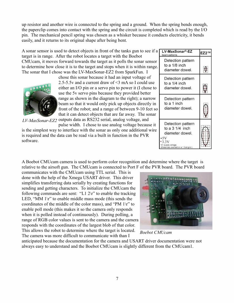
A sonar sensor is used to detect objects in front of the tanks gun to see if a target is in range. After the robot locates a target with the Boebot CMUcam, it moves forward towards the target as it polls the sonar sensor to determine how close it is to the target and stops when it is within range. The sonar that I chose was the LV-MaxSonar-EZ2 from SparkFun. I
chose this sonar because it had an input voltage of 2.5-5.5v and a current draw of <3 mA so I could use either an I/O pin or a servo pin to power it (I chose to use the 5v servo pins because they provided better range as shown in the diagram to the right); a narrow beam so that it would only pick up objects directly in front of the robot; and a range of between 9-10 feet so that it can detect objects that are far away. The sonar outputs data as RS232 serial, analog voltage, and pulse width. I chose to use analog voltage because it
is the simplest way to interface with the sonar as only one additional wire is required and the data can be read via a built in function in the PVR software.
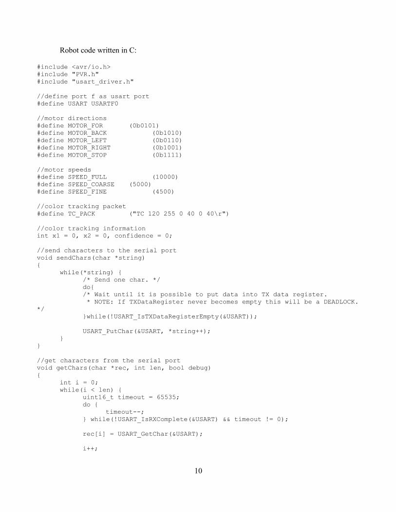
A Boebot CMUcam camera is used to perform color recognition and determine where the target is relative to the airsoft gun. The CMUcam is connected to Port F of the PVR board. The PVR board communicates with the CMUcam using TTL serial. This is done with the help of the Xmega USART driver. This driver simplifies transferring data serially by creating functions for sending and getting characters. To initialize the CMUcam the following commands are sent: “L1 2\r” to enable the tracking LED, “MM 1\r” to enable middle mass mode (this sends the coordinates of the middle of the color mass), and “PM 1\r” to enable poll mode (this makes it so the camera only responds when it is polled instead of continuously). During polling, a range of RGB color values is sent to the camera and the camera responds with the coordinates of the largest blob of that color. This allows the robot to determine where the target is located. The camera was more difficult to communicate with than I anticipated because the documentation for the camera and USART driver documentation were not always easy to understand and the Boebot CMUcam is slightly different from the CMUcam1.
7
LV-MaxSonar-EZ2
Boebot CMUcam

Behaviors
The tank initially starts out searching for the target. It moves forward while checking for the target for a certain amount of time then rotates around while looking for the target until it either finds the target or hits an obstacle. If the robot hits an obstacle, it backs up and turns then continues to search as described above. If the robot finds the target, it rotates left or right slightly as necessary until the target is centered with the gun. After the target is centered, the robot moves forward until the target is within range. The robot then checks to make sure that the target is still centered. After it centers the target again, it fires at the target and is finished. The status of the robot's behavior is displayed on the LCD screen for visual and debugging purposes.
Experimental Layouts and Results
The placement of the bump sensors required some adjusting. I tried different angles from 0 to 90 degrees to the direction the robot faces to determine what angles worked best when the robot is moving forward into something and when the robot is rotating into something. Originally I thought that I might need 4 bump sensors to detect both kinds of collisions, but when the bump sensors are angled at about 45 degrees to the direction the robot is facing, they work for both.
Conclusion
Seek and Destroy accomplishes its goal which is to find a colored target and shoot it. However it does not do it as well as I thought it would. This is mostly due to the CMUcam not performing as well as I expected. Much of the camera's performance is based on the lighting of the room that the robot is in. It does not always identify a target as I would expect it to and therefore can miss a target if the range of colors is set too low in poor lighting or have false positives if the range of colors is too high in a well lit area. Another problem that I had was with the delay between when the camera is polled for information and when the robot is able to react to the camera's response. I expected the delay to be shorter and in order to compensate, the speed of the robot had to be reduced.
If I were able to start this project over again, I would want to do it with a larger budget. I think that the robot would be able to better identify and possibly track a moving object if it had a webcam that was wirelessly interfaced to a laptop to offload the image processing. I think that this would allow a better camera to be used with a higher resolution without slowing the robot down as much. Knowing what I do now about motors I would have probably bought my own and designed my own robot chassis to better accommodate the components that I put inside. It is difficult to determine how quickly the motors will move the robot based on the power provided to them because of the weight of the robot and the friction that the treads can have on different surfaces. For example, the robot is able to move around on a carpet if more power is provided, but the same amount of power makes the robot move too quickly on a tile floor.
A lot of the time I spent on this project was on interfacing the different pieces of hardware together so I did not have as much time to work on the software. I had trouble making stable wire connections and had a few pieces of hardware fail. Despite the problems that I encountered, the robot successfully accomplishes its task.
8

Appendices
Wiring diagram:
9
Robot code written in C:
#include <avr/io.h>#include "PVR.h"#include "usart_driver.h"
//define port f as usart port#define USART USARTF0
//motor directions#define MOTOR_FOR (0b0101)#define MOTOR_BACK (0b1010)#define MOTOR_LEFT (0b0110)#define MOTOR_RIGHT (0b1001)#define MOTOR_STOP (0b1111)
//motor speeds#define SPEED_FULL (10000)#define SPEED_COARSE (5000)#define SPEED_FINE (4500)
//color tracking packet#define TC_PACK ("TC 120 255 0 40 0 40\r")
//color tracking informationint x1 = 0, x2 = 0, confidence = 0;
//send characters to the serial portvoid sendChars(char *string){
while(*string) {/* Send one char. */do{/* Wait until it is possible to put data into TX data register. * NOTE: If TXDataRegister never becomes empty this will be a DEADLOCK.
*/}while(!USART_IsTXDataRegisterEmpty(&USART));
USART_PutChar(&USART, *string++);}
}
//get characters from the serial portvoid getChars(char *rec, int len, bool debug){
int i = 0;while(i < len) {
uint16_t timeout = 65535;do {
timeout--;} while(!USART_IsRXComplete(&USART) && timeout != 0);
rec[i] = USART_GetChar(&USART);
i++;
10

}
if(debug) {lcdGoto(1, 0);for(int j = 0; j < 16; j++) {
lcdChar(rec[j]);}
}}
//initialize port f for TTL serial communications with the CMUcamvoid serialInit(void){
/* This PORT setting is only valid to USARTC0 if other USARTs is used a * different PORT and/or pins is used. *//* PIN3 (TXD0) as output. */PORTF.DIRSET = PIN3_bm;
/* PC2 (RXD0) as input. */PORTF.DIRCLR = PIN2_bm;
/* USARTC0, 8 Data bits, No Parity, 1 Stop bit. */USART_Format_Set(&USART, USART_CHSIZE_8BIT_gc, USART_PMODE_DISABLED_gc,
false);
/* Set Baudrate to 9600 bps: * Use the default I/O clock fequency that is 32 MHz. * Do not use the baudrate scale factor * * Baudrate select = ( (I/O clock frequency)/(baudrate * 16) ) - 1 */USART_Baudrate_Set(&USART, 207, 0);
/* Enable both RX and TX. */USART_Rx_Enable(&USART);USART_Tx_Enable(&USART);
}
void cameraInit(void){
sendChars("L1 2\r"); //turn on tracking lightsendChars("PM 1\r"); //turn on poll modesendChars("MM 1\r"); //turn on middle mass
}
void motorInit(void){
PORTH_DIR = 0b00000011; //set on/off port directionPORTH_OUT = 0b00000011;
}
//initialize I/O pins for the gunvoid gunInit(){
PORTQ_DIR = 0b0001;}
11

//initialize I/O pins for bump sensorsvoid bumpInit(){
PORTB_PIN0CTRL = 0b10011000;PORTB_DIR = 0;PORTJ_PIN7CTRL = 0b10011000;PORTJ_DIR = 0;
}
//read the left bump sensorbool readLeft() {
return !(PORTB_IN & 0b00000001);}
//read the right bump sensorbool readRight() {
return !(PORTJ_IN & 0b10000000);}
//read the sonar sensorint readSonar() {
return ADCA7() / 52; //sonar distance in inches}
void setMotor(int dir, long speed){
TCD0_CCA = (dir & 0b000001) ? speed : 0;TCD0_CCB = (dir & 0b000010) ? speed : 0;TCD0_CCC = (dir & 0b000100) ? speed : 0;TCD0_CCD = (dir & 0b001000) ? speed : 0;
}
//return an integer from a string starting at the index specified by 'start'int getInt(char *string, int start, int *end) {
int retVal = 0;while(true) {
if(48 <= string[start] && string[start] <= 57) {retVal = retVal * 10 + string[start] - 48;
}else {
break;}
start++;}
*end = start;
return retVal;}
//parse the response from the GM commandvoid parseGM(char *rec, int len, int *r, int *g, int *b){
for(int i = 0; i < len; i++) {if(rec[i] == 'S') {
12

int end;*r = getInt(rec, i + 2, &end);end++;*g = getInt(rec, end, &end);end++;*b = getInt(rec, end, &end);break;
}}
}
//parse the response from the TC commandvoid parseTC(char *rec, int len, int *mx, int *my, int *x1, int *y1, int *x2, int *y2, int *pixels, int *confidence){
for(int i = 0; i < len; i++) {if(rec[i] == 'M') {
int end;*mx = getInt(rec, i + 2, &end);end++;*my = getInt(rec, end, &end);end++;
*x1 = getInt(rec, end, &end);end++;*y1 = getInt(rec, end, &end);end++;*x2 = getInt(rec, end, &end);end++;*y2 = getInt(rec, end, &end);end++;
*pixels = getInt(rec, end, &end);end++;*confidence = getInt(rec, end, &end);break;
}}
}
//check the camera for coordinates of targetvoid checkCamera(){
int len = 80;char rec[len];x1 = 0;x2 = 0;confidence = 0;int mx = 0, my = 0, y1 = 0, y2 = 0, pixels = 0;sendChars(TC_PACK);getChars(rec, len, false);parseTC(rec, len, &mx, &my, &x1, &y1, &x2, &y2, &pixels, &confidence);
if(x1 == 0 && x2 == 0) {sendChars(TC_PACK);getChars(rec, len, false);parseTC(rec, len, &mx, &my, &x1, &y1, &x2, &y2, &pixels, &confidence);
13

}
/*lcdGoto(0, 0);lcdString("x1: ");lcdInt(x1);lcdString(" x2: ");lcdInt(x2);lcdGoto(1, 0);lcdString("px: ");lcdInt(pixels);lcdString(" cf: ");lcdInt(confidence);*/
}
//display output from TC commandvoid testTC(){
//while(true) {int len = 50;char rec[len];sendChars(TC_PACK);getChars(rec, len, false);
int mx = 0, my = 0, x1, y1, x2, y2, pixels, confidence;parseTC(rec, len, &mx, &my, &x1, &y1, &x2, &y2, &pixels, &confidence);lcdGoto(1, 0);lcdString(" ");lcdGoto(1, 0);lcdInt(mx);lcdChar(' ');lcdInt(my);delay_ms(500);
//}}
//display output from GM commandvoid testGM(){
int len = 50;char rec[len];sendChars("GM\r");getChars(rec, len, false);int r = -1, g = -1, b = -1;parseGM(rec, len, &r, &g, &b);lcdGoto(1, 0);lcdString(" ");lcdGoto(1, 0);lcdInt(r);lcdChar(' ');lcdInt(g);lcdChar(' ');lcdInt(b);delay_ms(500);
}
//turn on motor to fire gun then wait until it fires then turn it offvoid fire()
14

{PORTQ_OUT = 0b0001;delay_ms(2400);PORTQ_OUT = 0b0000;
}
//center robot on targetvoid center() {
lcdInit();lcdString("Centering");while(true) {
setMotor(MOTOR_STOP, 0);checkCamera();if(x2 <= 40) {
lcdGoto(1, 0);lcdString("Target to right");setMotor(MOTOR_RIGHT, SPEED_FINE);delay_ms(100);
}else if(x1 > 40) {
lcdGoto(1, 0);lcdString("Target to left");setMotor(MOTOR_LEFT, SPEED_FINE);delay_ms(100);
}else {
setMotor(MOTOR_STOP, 0);break;
}}
}
int main(void){
xmegaInit(); //setup XMegadelayInit(); //setup delay functionsServoCInit(); //setup PORTC ServosServoDInit(); //setup PORTD ServosADCAInit(); //setup PORTA analong
readingslcdInit(); //setup LCD on PORTKserialInit(); //setup serial
connection with cmucamcameraInit(); //setup camera as polledmotorInit(); //setup motor driver I/O
pinsgunInit(); //setup gun I/O pinbumpInit(); //setup bump sensor I/O
pins
//touch right bump sensorlcdInit();lcdString("touch right");while(!readRight()) {
testGM();}
15

//touch left bump sensorlcdInit();lcdString("touch left ");while(!readLeft()) {
testTC();}
//locate targetlcdInit();lcdString("Seeking");bool found = false;while(!found) {
//rotatefor(int i = 0; i < 4; i++) {
setMotor(MOTOR_STOP, 0);checkCamera();if(x1 == 0 && x2 == 0) {
setMotor(MOTOR_RIGHT, SPEED_COARSE);for(int j = 0; j < 5; j++) {
if(readRight()) {setMotor(MOTOR_LEFT, SPEED_COARSE);delay_ms(100);setMotor(MOTOR_BACK, SPEED_COARSE);delay_ms(500);
}delay_ms(100);
}}else if(confidence > 40) {
found = true;break;
}}
//move forwardfor(int i = 0; i < 3 && !found; i++) {
for(int j = 0; j < 20; j++) {if(readLeft()) {
setMotor(MOTOR_BACK, SPEED_COARSE);delay_ms(500);setMotor(MOTOR_RIGHT, SPEED_COARSE);delay_ms(750);setMotor(MOTOR_STOP, 0);
}else if(readRight()) {
setMotor(MOTOR_BACK, SPEED_COARSE);delay_ms(500);setMotor(MOTOR_LEFT, SPEED_COARSE);delay_ms(750);setMotor(MOTOR_STOP, 0);
}
setMotor(MOTOR_FOR, SPEED_COARSE);delay_ms(100);
}setMotor(MOTOR_STOP, 0);checkCamera();
16

if(confidence > 40) {found = true;break;
}}
}
//center robotcenter();
//move in rangelcdInit();lcdString("Out of range");int limit = 30;int sonar = limit + 1;while((sonar = readSonar()) > limit) {
setMotor(MOTOR_FOR, SPEED_COARSE);lcdGoto(1, 0);lcdString(" ");lcdGoto(1, 0);lcdString("Sonar: [");lcdInt(sonar);lcdChar('/');lcdInt(limit);lcdChar(']');
}
//center againcenter();
//firesetMotor(MOTOR_STOP, 0);lcdInit();lcdString("Firing Once");fire();lcdInit();lcdString("Firing Twice");fire();lcdInit();lcdString("Finished");
}
17