segway rmp experiments at georgia tech · segway rmp experiments at georgia tech darpa mars segway...
TRANSCRIPT

Segway RMP Experiments at Georgia Tech
DARPA MARS Segway WorkshopSeptember 23, 2003
Tom Collins

Major activities
n Interface to MissionLabn Teleoperation
experimentsn Use of laser range
finder for terrain characterization

Physical modificationsn Basic operation requires
mounting of only two components– Ruggedized case containing
laptop, power converters, 802.11, camera, and video encoder (on top plate, 4 bolts)
– Battery (on base, in custom bracket)
n SICK mount for laser experiments
n Optional protective kill switches (slight modification of UMassdesign)

Software and Interface
n Uses Kvaser LapCAN card for RMP interfacen RMP drivers run as part of HServer
application– HServer provides a uniform interface across
various robot platforms and sensors– RMP updates acquired at about 50 Hz
n MissionLab generates executable code for RMP like any other supported robot
n Interface to SICK and encoded video stream unchanged from our other platforms

Initial experiments
n Work stalled by bailment agreement
n Interface completed in lab during late July, with little actual robot usage
n Video shows first significant run –teleoperation at Ft. Benning

Lessons learned
n Only one unexplained instance of “dying” (in lab, very early in testing)
n Virtually no tipping until we started tryingn Vulnerable to tipping during sudden
acceleration in loose soil or graveln Hill climbing capabilities limitedn Battery power is impressive for vehicle sizen Speed, turning radius better than other
outdoor robots

Ft. Benning runs- MOUT

Ft. Benning run -- Sewer

Ft. Benning runs – Leader/Follower

Ft. Benning runs – Stress testing

Terrain characterization
n Laser rangefinders have been used extensively on robots– “On or near the ground”:
§ Road following§ Footfall selection § Vegetation characterization
– Localization and/or visualizationn RMP is at least as vulnerable to
discontinuities as a legged robotn RMP has a “free” tilt mechanismn Seems worthwhile to revisit the terrain issue
with the RMP in mind
Geometry of a SICK on the RMP
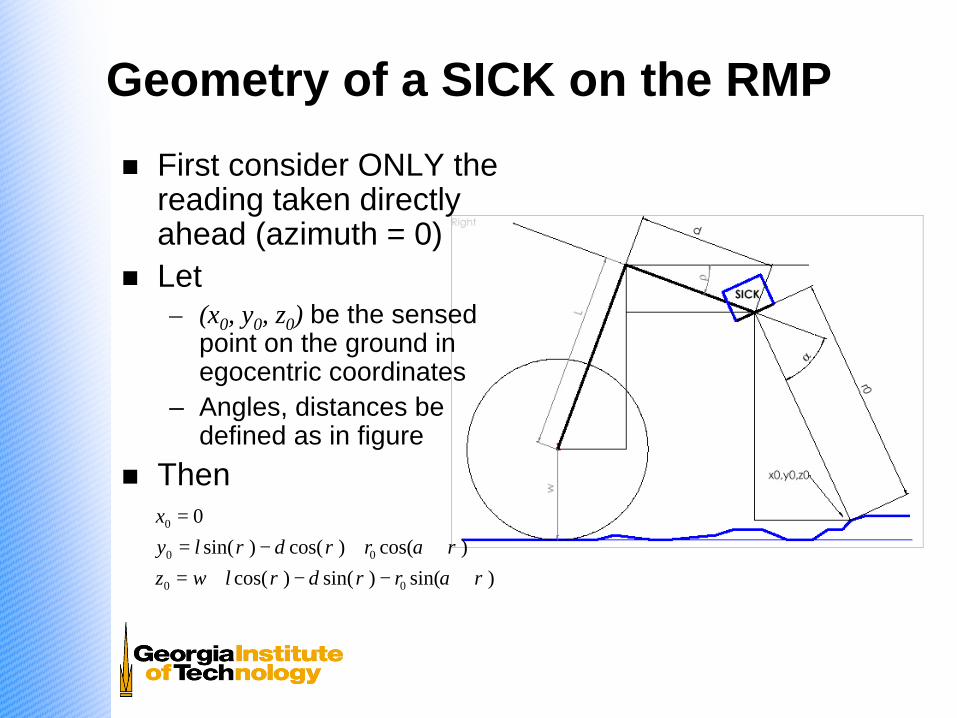
n First consider ONLY the reading taken directly ahead (azimuth = 0)
n Let – (x0, y0, z0) be the sensed
point on the ground in egocentric coordinates
– Angles, distances be defined as in figure
n Then
)sin()sin()cos()cos()cos()sin(
0
00
00
0
ραρρραρρ
+−−+=++−=
=
rdlwzrdly
x

RMP pitch behaviorn Data taken
directly from RMP pitch sensor
n Shows the “tip” needed to move across fairly level ground
Initiates motion Stops
Average Tilt

Closer look at pitchn “Gross” control
operates at ~0.15 Hz– varying with
payload, etc.– Maintains
speed?n Fine control
operates at about 1 Hz
n Hopefully, all of these effects can be made to disappear in range readings

Raw laser range readingsn Still considering
only the single reading straight ahead (and tilted down)
n Data taken during same maneuver as previous pitch data – During the active
movement phasen Note the
appearance of same frequencies
n More apparent when scaled sin(pitch) is superimposed (inset)
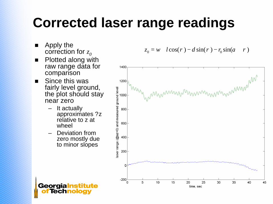
Corrected laser range readingsn Apply the
correction for z0n Plotted along with
raw range data for comparison
n Since this was fairly level ground, the plot should stay near zero– It actually
approximates ?z relative to z at wheel
– Deviation from zero mostly due to minor slopes
)sin()sin()cos( 00 ραρρ +−−+= rdlwz

Check for latency issuesn Pitch and range are
acquired from different devices
n Timestamps are applied at the computer running hServer
n Latency characteristics of RMP are unknown
n So, some high-frequency errors may be due to picking the “wrong” pitch data
n Graph shows that the best choice of pitch data is the most recent at the time of laser scan completion

3D terrain
n Use data for all azimuths, not just straight ahead
n Calculate x and y for every point

Terrain and obstacles
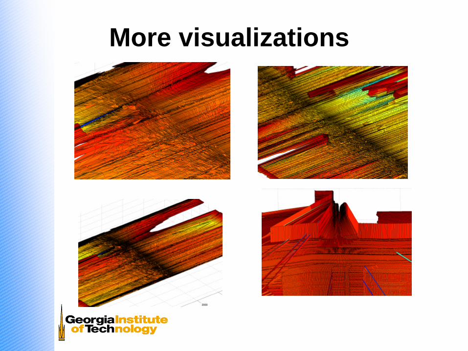
More visualizations

How this data can be usedn Autonomous operation
– Reactive sensing of terrain considerations (perceptual schemas)– Without even attempting to register data in a larger world map, it
provides§ Local positive and negative obstacles smaller than wheel width§ Sideslope of path ahead (RMP is vulnerable to side tipping)§ Fore/aft slope
– All of these features can be expressed as simple avoidance vectorsn Teleoperation
– Visualization of terrain (can be displayed alongside visual image)– Could be processed to produce simple operator cues (possibly
generated by same perceptual schemas above)– Low-light operation

Future work
n Full autonomous operationn Multiagent experiments
– Heterogeneous with existing GT robots– Homogeneous with MARS 2020 team
n Use SICK intensity information to display surface brightness (in IR)
n Estimation of surface material (sand, gravel, other “difficult” surfaces)