seirios - digitalcommons.usu.edu
TRANSCRIPT
SEIRIOS: A Demonstration of Space Infrared Interferometer
by Formation Flying of Micro-SatellitesSatoshi Ikari1,
Taro Matsuo2, Hirotaka Kondo1, Shinichi Nakasuka11. The University of Tokyo, 2. Nagoya University
1
Small Satellite Conference 2021SSC21-WKIV-04

Background
2

Infrared Astronomy
3
} The high angular resolution infrared astronomy is essential to reveal big questions on the universe.} History of the universe, galaxy formation, planetary formation, biomarker detection on exoplanet
} To achieve high angular resolution in the infrared region, long baseline space interferometer is required
100m Baseline
interferometer
J Dalcanton, S Seager, S Aigrain, C Hirata, S Battel, J Mather, N Brandt, M Postman, C Conroy, D Redding,and L Feinberg. From Cosmic Birth to Living Earths. Association of Universities for For Research inAstronomy, 2015.
Sandrine Thomas, Ruslan Belikov, and et al., “High-Contrast Imaging and the Direct Detection of Exoplanets”
Space Infrared Interferometers
4
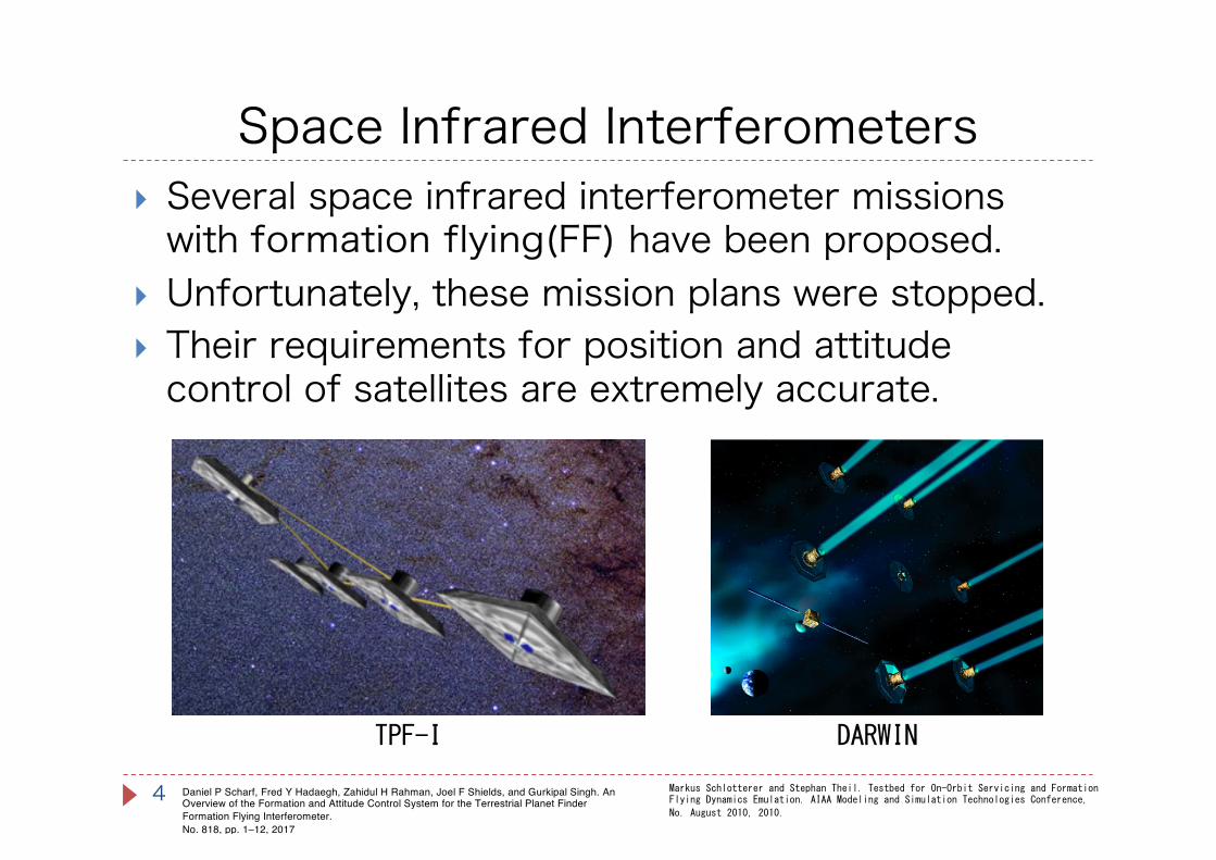
} Several space infrared interferometer missions with formation flying(FF) have been proposed.
} Unfortunately, these mission plans were stopped.} Their requirements for position and attitude control of satellites are extremely accurate.
Daniel P Scharf, Fred Y Hadaegh, Zahidul H Rahman, Joel F Shields, and Gurkipal Singh. An Overview of the Formation and Attitude Control System for the Terrestrial Planet Finder Formation Flying Interferometer.No. 818, pp. 1–12, 2017
Markus Schlotterer and Stephan Theil. Testbed for On-Orbit Servicing and Formation Flying Dynamics Emulation. AIAA Modeling and Simulation Technologies Conference,
No. August 2010, 2010.
TPF-I DARWIN

Space Infrared Interferometers
5
} Recently, the space infrared interferometer with FF is refocused.
} IRASSI: Far-infrared interferometer with multiple satellite swarms
} LIFE: Biomarker detection mission with nulling interferometer with spacecraft formation flying
LIFEIRASSI
https://www.life-space-mission.com/the-project/technology/
Hendrik Linz, Divya Bhatia, Luisa Buinhas, Matthias Lezius, Eloi Ferrer, Roger FÅNorstner, Kathrin Frankl,Mathias Philips-Blum, Meiko Steen, Ulf Bestmann, Wolfgang HÅNansel, Ronald Holzwarth, Oliver Krause, andThomas Pany. InfraRed astronomy satellite swarm interferometry (IRASSI): Overview and study results.Adv. Space Res., Vol. 65, No. 2, pp. 831–849, January 2020.
Technological issue of formation flying infrared interferometer
6
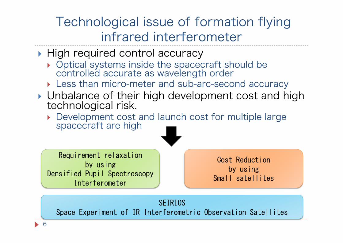
} High required control accuracy} Optical systems inside the spacecraft should be controlled accurate as wavelength order
} Less than micro-meter and sub-arc-second accuracy} Unbalance of their high development cost and high technological risk. } Development cost and launch cost for multiple large spacecraft are high
Requirement relaxationby using
Densified Pupil Spectroscopy Interferometer
Cost Reductionby using
Small satellites
SEIRIOSSpace Experiment of IR Interferometric Observation Satellites
Overview of SEIRIOS
7
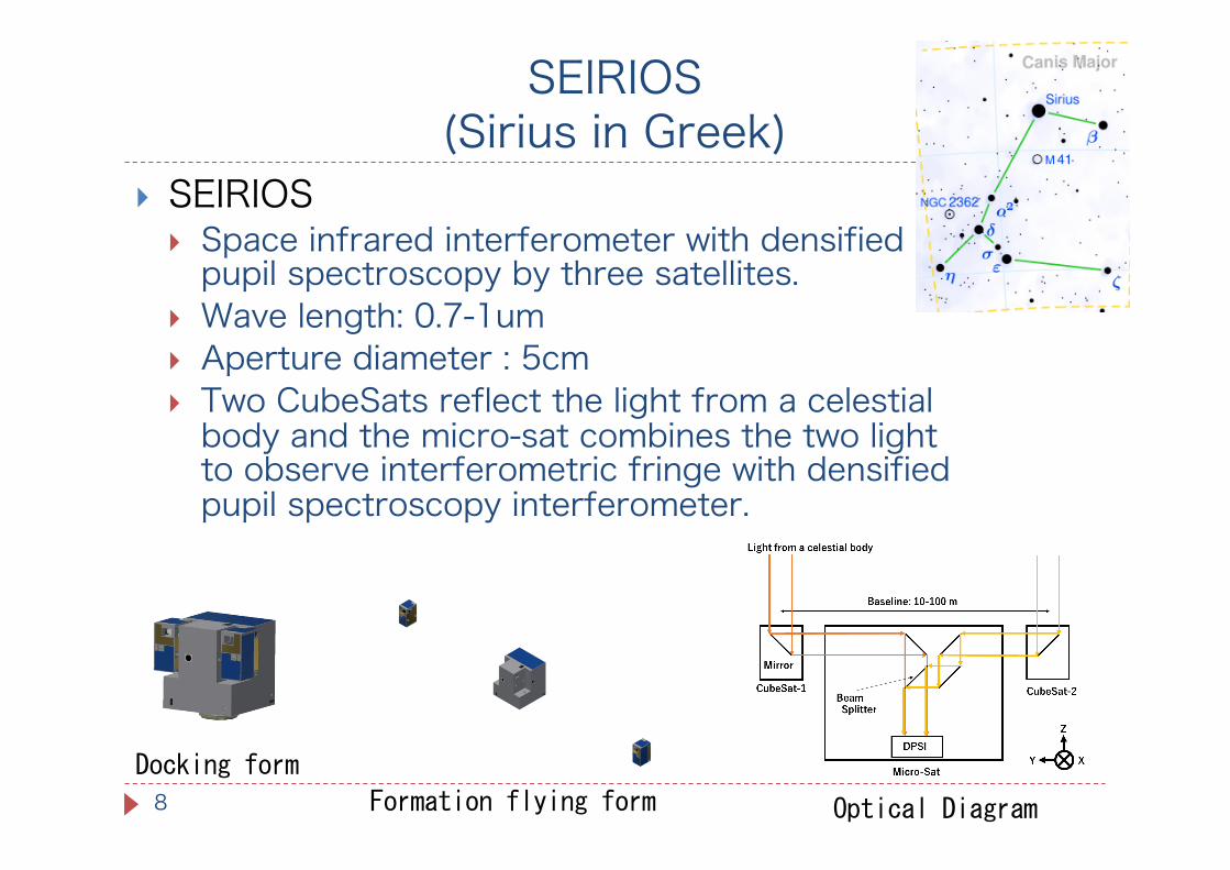
SEIRIOS(Sirius in Greek)
8
} SEIRIOS} Space infrared interferometer with densified pupil spectroscopy by three satellites.
} Wave length: 0.7-1um} Aperture diameter : 5cm} Two CubeSats reflect the light from a celestial body and the micro-sat combines the two light to observe interferometric fringe with densified pupil spectroscopy interferometer.
Docking form
Formation flying form Optical Diagram

Densified Pupil Spectroscopy Interferometer (DPSI)
9
} Two reflected beams are combined at the pupil plane not at the focal plane
} The combined beams at pupil plane are sliced} The sliced sub-pupils are densified by concave mirrors
} Input the densified sub-pupils to spectrographto get spectra of the bodies
Taro Matsuo, et al (2016) “A new concept for spectrophotometry of exoplanets with space-borne telescopes”

Requirement relaxation by DPSI
10
} We divide the control accuracy requirement:} Requirement to construct interferometric fringe
} Long term requirement
} Requirement to get clear interferometric fringe image} Short term requirement (during exposure time)
This requirement is dramatically relaxed
Requirement to construct interferometric fringe
11
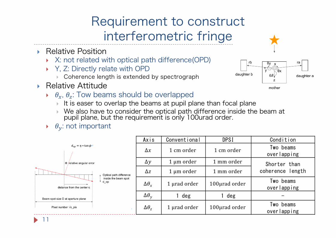
} Relative Position} X: not related with optical path difference(OPD)} Y, Z: Directly relate with OPD
} Coherence length is extended by spectrograph} Relative Attitude
} 𝜃!, 𝜃": Tow beams should be overlapped} It is easer to overlap the beams at pupil plane than focal plane} We also have to consider the optical path difference inside the beam at pupil plane, but the requirement is only 100urad order.
} 𝜃#: not important
Axis Conventional DPSI Condition
Δ𝑥 1 cm order 1 cm order Two beams overlapping
Δ𝑦 1 µm order 1 mm order Shorter than coherence lengthΔ𝑧 1 µm order 1 mm order
Δ𝜃𝑥 1 µrad order 100µrad order Two beams overlapping
Δ𝜃𝑦 1 deg 1 deg -
Δ𝜃𝑧 1 µrad order 100µrad order Two beams overlapping
Requirement to get clear interferometric fringe
12
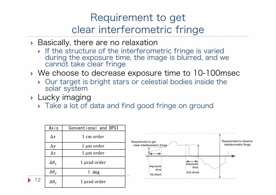
} Basically, there are no relaxation} If the structure of the interferometric fringe is varied during the exposure time, the image is blurred, and wecannot take clear fringe
} We choose to decrease exposure time to 10-100msec} Our target is bright stars or celestial bodies inside thesolar system
} Lucky imaging } Take a lot of data and find good fringe on ground
Axis Conventional and DPSI
Δ𝑥 1 cm order
Δ𝑦 1 µm orderΔ𝑧 1 µm order
Δ𝜃𝑥 1 µrad order
Δ𝜃𝑦 1 deg
Δ𝜃𝑧 1 µrad order
Conceptual Design of SEIRIOS
13
SEIRIOSMission sequence and success criteria
14
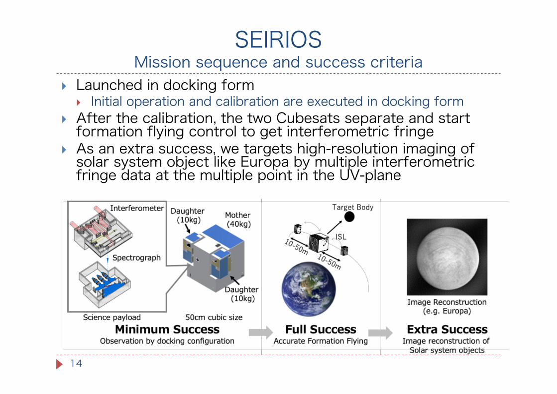
} Launched in docking form} Initial operation and calibration are executed in docking form
} After the calibration, the two Cubesats separate and startformation flying control to get interferometric fringe
} As an extra success, we targets high-resolution imaging of solar system object like Europa by multiple interferometric fringe data at the multiple point in the UV-plane

Orbit design
15
} We choose LEO since there are a lot of ride share chance
} The three satellites fly along-track formation in sun-synchronous circular orbit} The orbital plane is nearly perpendicular with target bodies
} The periodic relative orbit to keep the baseline vector perpendicular with target direction} The relative orbital element (ROE) is decided by
} Satellite distance (baseline distance) and direction of target body
OE MicroSat
𝑎 6928km
𝑒 0
𝑖 97.59deg
Ω 176.6deg
𝜔 0deg
𝑓 0deg
ROE CubeSat1 CubeSat2
𝑎𝛿𝑎 0
𝑎𝛿𝜆 10 m -10 m
𝑎𝛿𝑒! 0
𝑎𝛿𝑒" 0
𝑎𝛿𝑖! 0.54 m -0.54 m
𝑎𝛿𝑖" 0.84 m -0.84 m
Micro-sat
CubeSats
Target body direction𝛼:Ascending node𝛿:Declination
Kondo, Ishiwata, Ikari, et al., “Fuel Optimal Path Planning For an Earth Orbiting Linear Space
Interferometer”, Astrodynamics Specialist Conference, 2020
Conceptual Design of SEIRIOS
16
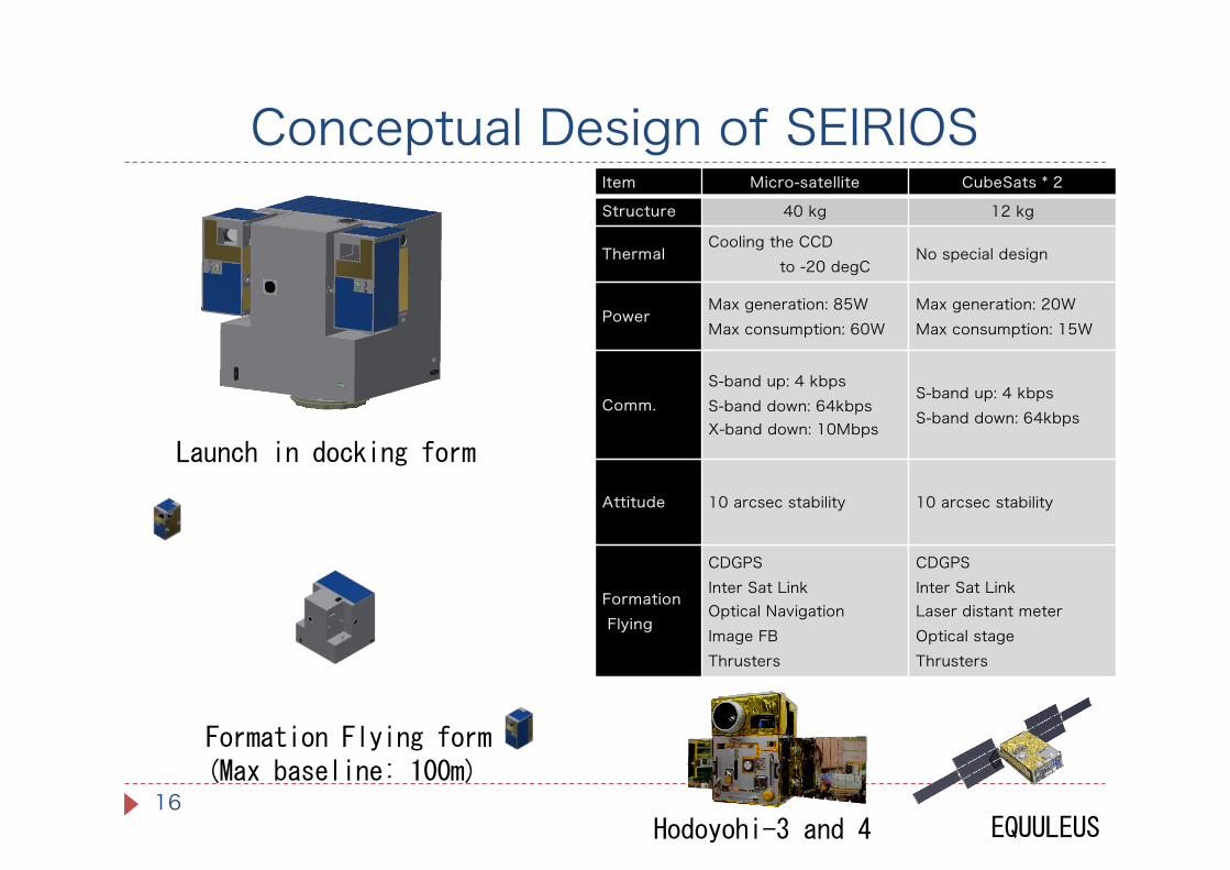
Item Micro-satellite CubeSats * 2
Structure 40 kg 12 kg
ThermalCooling the CCD
to -20 degCNo special design
PowerMax generation: 85WMax consumption: 60W
Max generation: 20WMax consumption: 15W
Comm.S-band up: 4 kbpsS-band down: 64kbpsX-band down: 10Mbps
S-band up: 4 kbpsS-band down: 64kbps
Attitude 10 arcsec stability 10 arcsec stability
FormationFlying
CDGPSInter Sat LinkOptical NavigationImage FBThrusters
CDGPSInter Sat LinkLaser distant meterOptical stageThrusters
Launch in docking form
Formation Flying form(Max baseline: 100m)
EQUULEUSHodoyohi-3 and 4

Accurate Control
17
} To achieve 1mm order position control accuracy} Image feedback from the DPSI
} Two optical cameras to measure relative attitude of two reflected beam and optical path difference
} Delay line control by CubeSats
Delay line controller

Control Simulation and Experiment
18
} We developed numerical simulator to confirm the control accuracy of spacecraft
} We also developed ground testbed for delay line control and get interferometric fringe
Result of Numerical simulation
Optical path difference without delay line controlTestbed for delay line control

Simulation for image reconfiguration
19 UV-plane Reconfigured Image
Observation duration [day]
Case 1

Summary
20
} We proposed a novel formation flying infraredinterferometer with DPSI.
} The DPSI can relax control requirements} Optical path difference from 1um order to 1mm order} Relative attitude control from 1urad to 100urad.
} We proposed SEIRIOS to demonstrate the formation flying interferometer with DPSI
} The conceptual design shows that SEIRIOS could be realized by one 40-kg micro-satellite and two 10-kg CubeSats.
} We are trying to get grant to develop SEIRIOS in near future