seismic behavior of a low-rise horizontal cylindrical tank · seismic behavior of a low‑rise...
TRANSCRIPT
Vol.:(0123456789)1 3
International Journal of Advanced Structural Engineering (2018) 10:143–152 https://doi.org/10.1007/s40091-018-0188-y
ORIGINAL RESEARCH
Seismic behavior of a low‑rise horizontal cylindrical tank
Alessandra Fiore1,2 · Carlo Rago3 · Ivo Vanzi1,3,4 · Rita Greco5 · Bruno Briseghella4
Received: 10 January 2018 / Accepted: 2 May 2018 / Published online: 12 May 2018 © The Author(s) 2018
AbstractCylindrical storage tanks are widely used for various types of liquids, including hazardous contents, thus requiring suit-able and careful design for seismic actions. The study herein presented deals with the dynamic analysis of a ground-based horizontal cylindrical tank containing butane and with its safety verification. The analyses are based on a detailed finite ele-ment (FE) model; a simplified one-degree-of-freedom idealization is also set up and used for verification of the FE results. Particular attention is paid to sloshing and asynchronous seismic input effects. Sloshing effects are investigated according to the current literature state of the art. An efficient methodology based on an “impulsive-convective” decomposition of the container-fluid motion is adopted for the calculation of the seismic force. The effects of asynchronous ground motion are studied by suitable pseudo-static analyses. Comparison between seismic action effects, obtained with and without considera-tion of sloshing and asynchronous seismic input, shows a rather important influence of these conditions on the final results.
Keywords Cylindrical tank · Sloshing · Asynchronous seismic action · FE modeling · Seismic behavior
Introduction
Seismic loading can induce large damages in industrial facilities and their complex components (Babič and Dolšek 2016; Demartino et al. 2017a, b; Nuti et al. 2009). The loss of the structural integrity of these structures can have severe consequences on the population, the environment and the economy (Krausmann et al. 2010; Fiorentino et al. 2015; Rodrigues et al. 2017). Looking at power/chemical/petrochemical plants, storage tanks containers are widely employed. These hold liquids, compressed gases or medi-ums used for the short- or long-term storage of heat or cold.
Liquid storage tanks and piping systems are considered as critical components of those industrial facilities (Vathi et al. 2017; Bakalis et al. 2017).
The seismic response of tanks has been widely studied in the past starting from the pioneering studies of Housner (1957, 1963). In particular, Housner (1957) first presented the simplified formulae to compute the dynamic pressures developed on accelerated liquid containers and successively (Housner 1963) studied the dynamic behavior of ground-supported elevated water tanks considering equivalent spring–mass systems. Current practice for the seismic design of storage tanks is mainly based on Appendix E of API 650 (2007) standard and on Eurocode 8 (1998). Generally speak-ing, there are many different types of equipment used for the storage of liquids and gases. The characteristics of the differ-ent tanks adopted mainly depend on: (a) the quantity of fluid being stored, (b) the nature of the fluid, (c) the physical state of the fluid and (d) the temperature and pressure. In industrial plants, gases are usually stored under high-pressure, often in liquid form since the volume is largely reduced. Within this framework, ground-based horizontal cylindrical tanks resting upon two supports are used mainly for storage of various liq-uids. The capacity of such tanks considerably exceeds those of horizontal tanks designed for land transportation. Under the conditions of normal exploitation, such tanks are loaded mainly with internal pressure being the sum of hydrostatic
* Alessandra Fiore [email protected]
1 InGeo, University of Chieti-Pescara “G. d’Annunzio”, Viale Pindaro 42, 65127 Pescara, Italy
2 DICAR , Politecnico di Bari, Via Orabona 4, 70125 Bari, Italy
3 Next Innovation in Engineering, Spin-Off University of Chieti-Pescara “G. d’Annunzio”, Seconda traversa Strettola Sant’Anna alle Paludi n. 11, 80142 Naples, Italy
4 College of Civil Engineering, Fuzhou University, Fuzhou 350108, Fujian, China
5 DICATECh, Technical University of Bari, Via Orabona 4, 70125 Bari, Italy
144 International Journal of Advanced Structural Engineering (2018) 10:143–152
1 3
pressure and the uniform pressure caused by vapor of the medium contained therein (Magnucki et al. 2004).
For a cylindrical pressure vessel, there are two possible failure modes. One is the maximum stresses reaching the yield condition and then yielding zone spread leading to final plastic collapse and the other is elastic or elastic–plas-tic buckling leading to collapse. For the first problem it is mainly a stress analysis while for the second problem it is a stability analysis. In particular this instability appears usu-ally in two forms: the elephant foot buckling and the dia-mond buckling (Niwa and Clough 1982; Haroun and Bhatia 1994; Hamdan 2000). The first form, which is an outward bulge located just above the tank base, results from the com-bined action of vertical compressive stresses, exceeding the critical stress, and hoop tension close to the yield limit. The second form is an elastic instability phenomenon due to the presence of high axial compressive stresses.
For sake of brevity, this study exclusively deals with stress analysis, while stability analysis is not documented.
More in detail, the present paper analyses the seismic performances of a ground-based horizontal cylindrical tank containing “butane”, focusing on the two topics of sloshing (1) and asynchronous seismic input (2).
As to the first aspect (1), it is worth noting that the seis-mic analysis of cylindrical storage tanks requires account-ing for the fluid–structure interaction. This phenomenon, referred to as “liquid sloshing,” is generated by the presence of a free surface allowing for fluid motions and is generally caused by external tank excitation, significantly affecting in many cases the dynamic response (Hamdan 2000; Patkas and Karamanos 2007).
As to the second aspect (2), asynchronous motion denotes the differences in amplitude, phase and frequency content among ground motions recorded over extended areas (Nuti and Vanzi 2005; Lavorato et al. 2017). This spatio-temporal variation of ground motion is mainly attributed to (Zerva 2009; Koufoudi et al. 2018): (a) difference in arrival times of seismic waves at different locations; (b) loss of coherence of seismic waves (i.e. gradual reduction of its statistical depend-ence on distance and frequency), due to multiple reflection and refraction as they propagate through the highly inho-mogeneous soil medium; (c) ground motion attenuation; (d) impact of local site effects. According to the current Italian and European technical codes (M.I.T 2008, Eurocode 8), if foundations are not properly interconnected with sufficiently rigid elements, asynchronous motion has to be accounted for.
The analysis herein presented comprises a sophisticated numerical FE modeling as well as a simplified model for the estimation of the dynamic properties of the tank structure. The paper is organized as follows: First, the steel cylindri-cal pressure vessel containing butane adopted for the case study is presented (“Case-study” section). “Sloshing” and “Asynchronous seismic input and resulting structural
demand” sections describe the mathematical model adopted for accounting for the sloshing and the asynchronous seis-mic input, while “Verification of finite element modeling” section focuses on the fundamental period of the structure. Results of the analyses are given in “Stress analysis” section; finally, conclusions are given in “Conclusions” section.
Case‑study
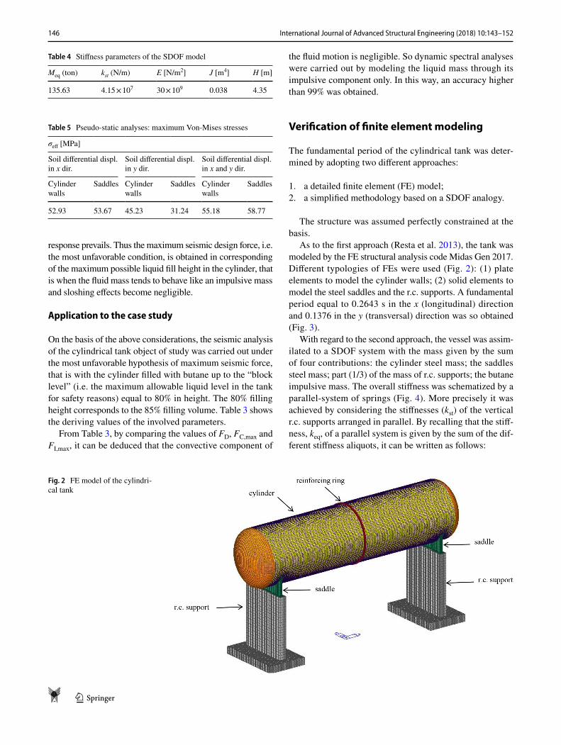
The research focuses on an existing ground-based horizon-tal cylindrical steel vessel resting upon two r.c. supports through steel saddles and containing pressurized butane (density ρL = 603 kg/m3). The cylinder is 14.66 m long, with external diameter and thickness equal to 4 m and 12 mm, respectively. The lateral sides of the cylinder are consti-tuted by curvilinear surfaces; a reinforcing steel ring can be observed at the middle of the cylinder (Fig. 2).
The geometrical and mechanical characteristics of the cylindrical vessel are summarized in Tables 1 and 2.
By observing Table 2, it can be noted that a rather low design strength (15 MPa) is attributed to r.c. supports. This choice was made for sake of safety since, in the absence of suitable test survey on the tank under examination, test results on adjacent vessels had highlighted low quality concrete.
Seismic input is given using the acceleration response spectrum defined according to the Italian code (M.I.T 2008). The following design conditions are adopted:
• nominal expected life of the structure: Vn = 50 years;• utilization coefficient of the structure: 4th Class (Cu= 2);• reference period for the seismic action: VR = 100 years;• behavior factor: q = 1.
Seismic zone is identified by the following characteris-tics: ground type: C; soil type T1 (S = 1.5).
Seismic hazard parameters of the site are given by:
Table 1 Geometrical properties of the cylindrical vessel
External diameter of the cylinder, m 4Thickness of the cylinder walls, m 0.012Height of the r.c. supports, m 3.35Width of the steel saddles, m 3.45Thickness of the steel saddles, m 0.02
Table 2 Mechanical properties of the cylindrical vessel
Design strength of cylinder steel (fd) (MPa) 360Design strength of supporting saddles steel (fd) (MPa) 230Design strength of r.c. supports (fd) (MPa) 15
145International Journal of Advanced Structural Engineering (2018) 10:143–152
1 3
• design ground acceleration for the no-collapse require-ment (ultimate limit state): ag = 0.053 g;
• maximum amplification factor of the acceleration response spectrum: F0 = 2.571;
• upper period of the constant acceleration branch of the response spectrum: TC
* = 0.512 s.
The above values are representative of low seismicity areas in Italy (Vanzi et al. 2015; Fiorentino et al. 2018).
Sloshing
Seismic design provisions of liquid-storage tanks such as API 650 (2007) and Eurocode 8 (1998) are based on a mechanical spring-mass analogy initially developed by Gra-ham and Rodriguez (1952), Jacobsen (1949) and Housner (1963) for rigid tanks and by Haroun and Housner (1982) for flexible tanks.
According to this analogy, a tank subjected to a seismic motion may be reduced to a simpler model with lumped masses and springs. More precisely a portion of the mass of the liquid content (MI) is considered as rigidly connected to the tank walls while the remaining portion (MC) is flex-ibly attached to the tank walls. The liquid (with mass MI) that synchronizes with the vibration of the tank is called impulsive while the sloshing component of the fluid (with mass MC), generating free surface waves and characterized by its own frequency of vibration, is referred to as convec-tive component.
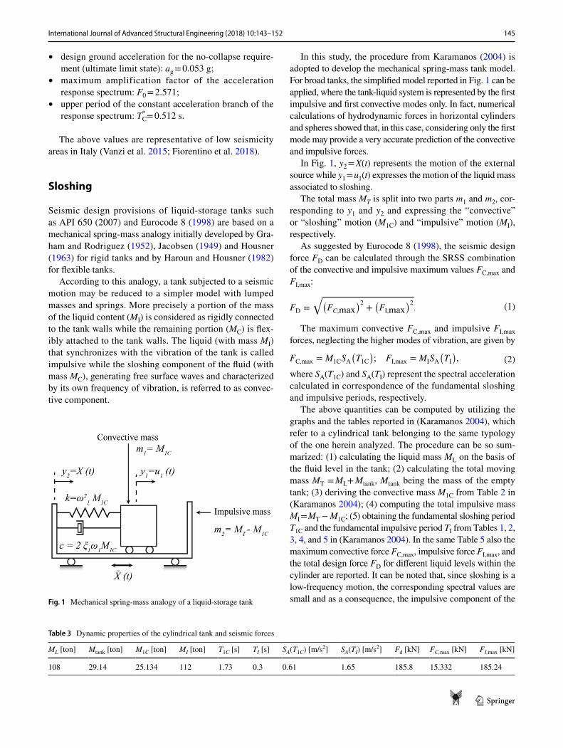
In this study, the procedure from Karamanos (2004) is adopted to develop the mechanical spring-mass tank model. For broad tanks, the simplified model reported in Fig. 1 can be applied, where the tank-liquid system is represented by the first impulsive and first convective modes only. In fact, numerical calculations of hydrodynamic forces in horizontal cylinders and spheres showed that, in this case, considering only the first mode may provide a very accurate prediction of the convective and impulsive forces.
In Fig. 1, y2 = X(t) represents the motion of the external source while y1 = u1(t) expresses the motion of the liquid mass associated to sloshing.
The total mass MT is split into two parts m1 and m2, cor-responding to y1 and y2 and expressing the “convective” or “sloshing” motion (M1C) and “impulsive” motion (MI), respectively.
As suggested by Eurocode 8 (1998), the seismic design force FD can be calculated through the SRSS combination of the convective and impulsive maximum values FC,max and FI,max:
The maximum convective FC,max and impulsive FI,max forces, neglecting the higher modes of vibration, are given by
where SA(T1C) and SA(TI) represent the spectral acceleration calculated in correspondence of the fundamental sloshing and impulsive periods, respectively.
The above quantities can be computed by utilizing the graphs and the tables reported in (Karamanos 2004), which refer to a cylindrical tank belonging to the same typology of the one herein analyzed. The procedure can be so sum-marized: (1) calculating the liquid mass ML on the basis of the fluid level in the tank; (2) calculating the total moving mass MT = ML+ Mtank, Mtank being the mass of the empty tank; (3) deriving the convective mass M1C from Table 2 in (Karamanos 2004); (4) computing the total impulsive mass MI = MT − M1C; (5) obtaining the fundamental sloshing period T1C and the fundamental impulsive period TI from Tables 1, 2, 3, 4, and 5 in (Karamanos 2004). In the same Table 5 also the maximum convective force FC,max, impulsive force FI,max, and the total design force FD for different liquid levels within the cylinder are reported. It can be noted that, since sloshing is a low-frequency motion, the corresponding spectral values are small and as a consequence, the impulsive component of the
(1)FD =
√
(
FC,max)2
+
(
FI,max)2.
(2)FC,max = M1CSA(
T1C)
; FI,max = MISA(
TI)
,
Fig. 1 Mechanical spring-mass analogy of a liquid-storage tank
Table 3 Dynamic properties of the cylindrical tank and seismic forces
ML [ton] Mtank [ton] M1C [ton] MI [ton] T1C [s] TI [s] SA(T1C) [m/s2] SA(TI) [m/s2] Fd [kN] FC,max [kN] FI,max [kN]
108 29.14 25.134 112 1.73 0.3 0.61 1.65 185.8 15.332 185.24
146 International Journal of Advanced Structural Engineering (2018) 10:143–152
1 3
response prevails. Thus the maximum seismic design force, i.e. the most unfavorable condition, is obtained in corresponding of the maximum possible liquid fill height in the cylinder, that is when the fluid mass tends to behave like an impulsive mass and sloshing effects become negligible.
Application to the case study
On the basis of the above considerations, the seismic analysis of the cylindrical tank object of study was carried out under the most unfavorable hypothesis of maximum seismic force, that is with the cylinder filled with butane up to the “block level” (i.e. the maximum allowable liquid level in the tank for safety reasons) equal to 80% in height. The 80% filling height corresponds to the 85% filling volume. Table 3 shows the deriving values of the involved parameters.
From Table 3, by comparing the values of FD, FC,max and FI,max, it can be deduced that the convective component of
the fluid motion is negligible. So dynamic spectral analyses were carried out by modeling the liquid mass through its impulsive component only. In this way, an accuracy higher than 99% was obtained.
Verification of finite element modeling
The fundamental period of the cylindrical tank was deter-mined by adopting two different approaches:
1. a detailed finite element (FE) model;2. a simplified methodology based on a SDOF analogy.
The structure was assumed perfectly constrained at the basis.
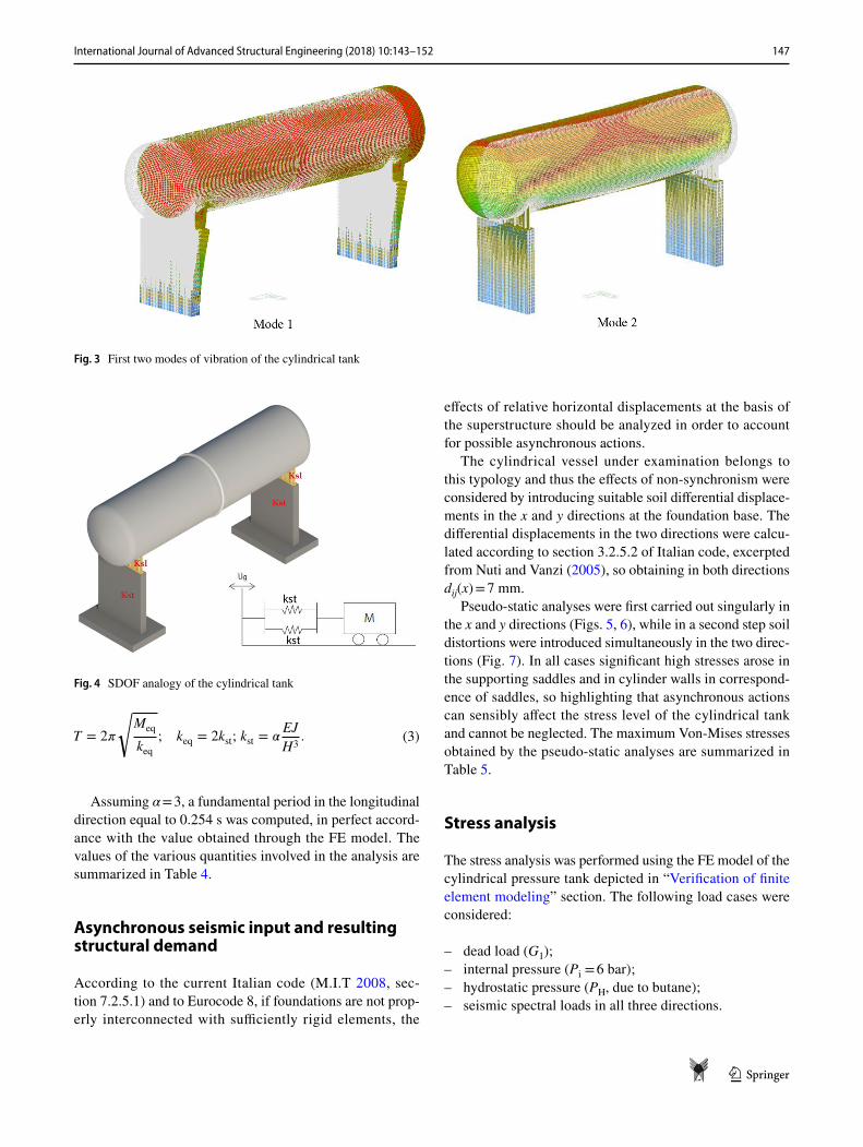
As to the first approach (Resta et al. 2013), the tank was modeled by the FE structural analysis code Midas Gen 2017. Different typologies of FEs were used (Fig. 2): (1) plate elements to model the cylinder walls; (2) solid elements to model the steel saddles and the r.c. supports. A fundamental period equal to 0.2643 s in the x (longitudinal) direction and 0.1376 in the y (transversal) direction was so obtained (Fig. 3).
With regard to the second approach, the vessel was assim-ilated to a SDOF system with the mass given by the sum of four contributions: the cylinder steel mass; the saddles steel mass; part (1/3) of the mass of r.c. supports; the butane impulsive mass. The overall stiffness was schematized by a parallel-system of springs (Fig. 4). More precisely it was achieved by considering the stiffnesses (kst) of the vertical r.c. supports arranged in parallel. By recalling that the stiff-ness, keq, of a parallel system is given by the sum of the dif-ferent stiffness aliquots, it can be written as follows:
Table 4 Stiffness parameters of the SDOF model
Meq (ton) kst (N/m) E [N/m2] J [m4] H [m]
135.63 4.15 × 10⁷ 30 × 109 0.038 4.35
Table 5 Pseudo-static analyses: maximum Von-Mises stresses
σeff [MPa]
Soil differential displ. in x dir.
Soil differential displ. in y dir.
Soil differential displ. in x and y dir.
Cylinder walls
Saddles Cylinder walls
Saddles Cylinder walls
Saddles
52.93 53.67 45.23 31.24 55.18 58.77
Fig. 2 FE model of the cylindri-cal tank
147International Journal of Advanced Structural Engineering (2018) 10:143–152
1 3
Assuming α = 3, a fundamental period in the longitudinal direction equal to 0.254 s was computed, in perfect accord-ance with the value obtained through the FE model. The values of the various quantities involved in the analysis are summarized in Table 4.
Asynchronous seismic input and resulting structural demand
According to the current Italian code (M.I.T 2008, sec-tion 7.2.5.1) and to Eurocode 8, if foundations are not prop-erly interconnected with sufficiently rigid elements, the
(3)T = 2�
√
Meq
keq; keq = 2kst; kst = �
EJ
H3.
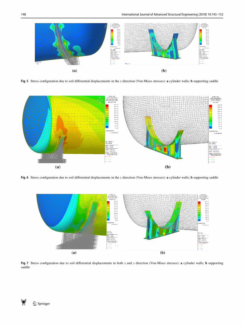
effects of relative horizontal displacements at the basis of the superstructure should be analyzed in order to account for possible asynchronous actions.
The cylindrical vessel under examination belongs to this typology and thus the effects of non-synchronism were considered by introducing suitable soil differential displace-ments in the x and y directions at the foundation base. The differential displacements in the two directions were calcu-lated according to section 3.2.5.2 of Italian code, excerpted from Nuti and Vanzi (2005), so obtaining in both directions dij(x) = 7 mm.
Pseudo-static analyses were first carried out singularly in the x and y directions (Figs. 5, 6), while in a second step soil distortions were introduced simultaneously in the two direc-tions (Fig. 7). In all cases significant high stresses arose in the supporting saddles and in cylinder walls in correspond-ence of saddles, so highlighting that asynchronous actions can sensibly affect the stress level of the cylindrical tank and cannot be neglected. The maximum Von-Mises stresses obtained by the pseudo-static analyses are summarized in Table 5.
Stress analysis
The stress analysis was performed using the FE model of the cylindrical pressure tank depicted in “Verification of finite element modeling” section. The following load cases were considered:
– dead load (G1);– internal pressure (Pi = 6 bar);– hydrostatic pressure (PH, due to butane);– seismic spectral loads in all three directions.
Fig. 3 First two modes of vibration of the cylindrical tank
Fig. 4 SDOF analogy of the cylindrical tank
148 International Journal of Advanced Structural Engineering (2018) 10:143–152
1 3
Fig. 5 Stress configuration due to soil differential displacements in the x direction (Von-Mises stresses): a cylinder walls; b supporting saddle
Fig. 6 Stress configuration due to soil differential displacements in the y direction (Von-Mises stresses): a cylinder walls; b supporting saddle
Fig. 7 Stress configuration due to soil differential displacements in both x and y direction (Von-Mises stresses): a cylinder walls; b supporting saddle
149International Journal of Advanced Structural Engineering (2018) 10:143–152
1 3
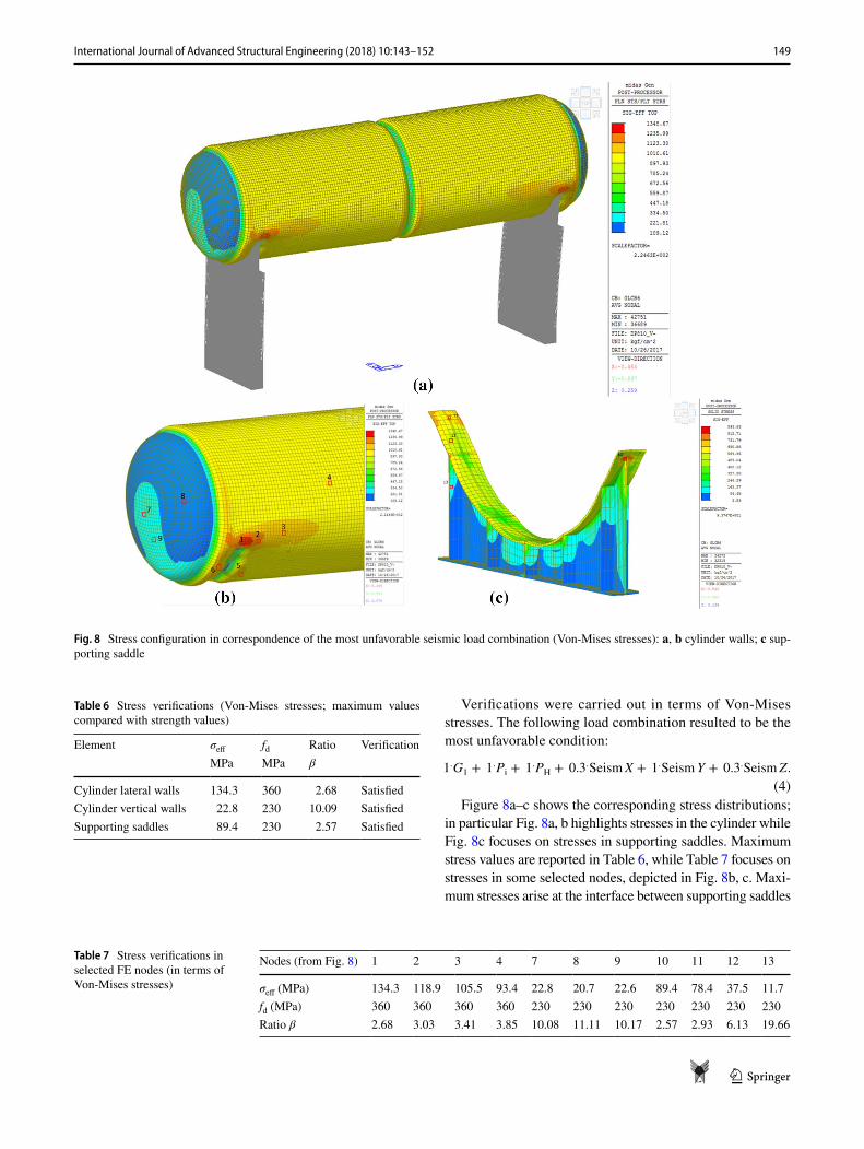
Verifications were carried out in terms of Von-Mises stresses. The following load combination resulted to be the most unfavorable condition:
Figure 8a–c shows the corresponding stress distributions; in particular Fig. 8a, b highlights stresses in the cylinder while Fig. 8c focuses on stresses in supporting saddles. Maximum stress values are reported in Table 6, while Table 7 focuses on stresses in some selected nodes, depicted in Fig. 8b, c. Maxi-mum stresses arise at the interface between supporting saddles
(4)1.G1 + 1.Pi + 1.PH + 0.3.SeismX + 1.SeismY + 0.3.Seism Z.
Fig. 8 Stress configuration in correspondence of the most unfavorable seismic load combination (Von-Mises stresses): a, b cylinder walls; c sup-porting saddle
Table 6 Stress verifications (Von-Mises stresses; maximum values compared with strength values)
Element σeff fd Ratio VerificationMPa MPa β
Cylinder lateral walls 134.3 360 2.68 SatisfiedCylinder vertical walls 22.8 230 10.09 SatisfiedSupporting saddles 89.4 230 2.57 Satisfied
Table 7 Stress verifications in selected FE nodes (in terms of Von-Mises stresses)
Nodes (from Fig. 8) 1 2 3 4 7 8 9 10 11 12 13
σeff (MPa) 134.3 118.9 105.5 93.4 22.8 20.7 22.6 89.4 78.4 37.5 11.7fd (MPa) 360 360 360 360 230 230 230 230 230 230 230Ratio β 2.68 3.03 3.41 3.85 10.08 11.11 10.17 2.57 2.93 6.13 19.66
150 International Journal of Advanced Structural Engineering (2018) 10:143–152
1 3
and cylinder walls, that is in corresponding of the constraint sections, where, in absence of section increments, a stress increase is reasonable.
As it emerges from Tables 6 to 7, in all elements maxi-mum stresses are lower than the corresponding design limit strengths, that is the analyzed cylindrical tank has a good level of safety against seismic action. Verifications on RC supports are not documented due to the absence of experimental tests on steel reinforcement details. However, it can be argued that they behave like perfectly constrained shelves, mainly stressed in the x direction, and at most the low seismic forces acting on them can lead to the early formation of plastic hinges at the basis, with low ductility involvement (Fiore et al. 2016; Imperatore et al. 2012; Lavorato and Nuti 2010; Lavorato et al. 2015; Zhou et al. 2015).
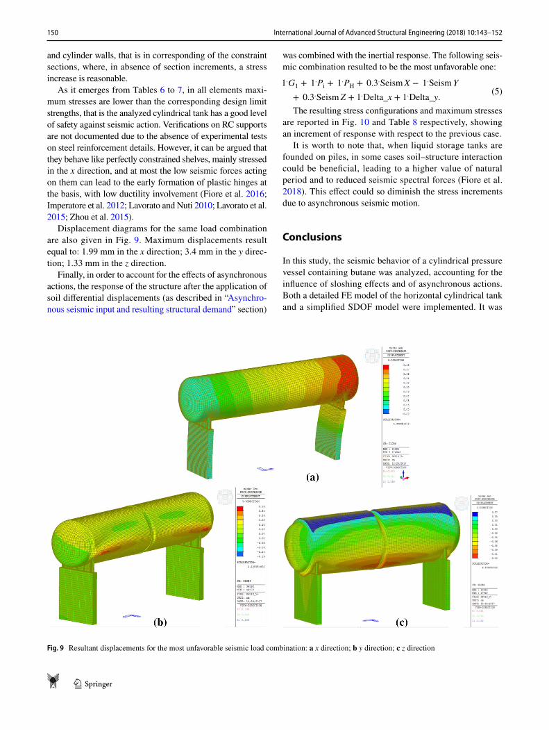
Displacement diagrams for the same load combination are also given in Fig. 9. Maximum displacements result equal to: 1.99 mm in the x direction; 3.4 mm in the y direc-tion; 1.33 mm in the z direction.
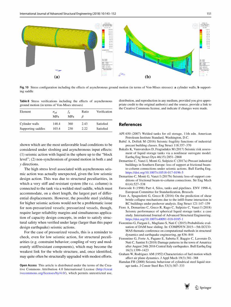
Finally, in order to account for the effects of asynchronous actions, the response of the structure after the application of soil differential displacements (as described in “Asynchro-nous seismic input and resulting structural demand” section)
was combined with the inertial response. The following seis-mic combination resulted to be the most unfavorable one:
The resulting stress configurations and maximum stresses are reported in Fig. 10 and Table 8 respectively, showing an increment of response with respect to the previous case.
It is worth to note that, when liquid storage tanks are founded on piles, in some cases soil–structure interaction could be beneficial, leading to a higher value of natural period and to reduced seismic spectral forces (Fiore et al. 2018). This effect could so diminish the stress increments due to asynchronous seismic motion.
Conclusions
In this study, the seismic behavior of a cylindrical pressure vessel containing butane was analyzed, accounting for the influence of sloshing effects and of asynchronous actions. Both a detailed FE model of the horizontal cylindrical tank and a simplified SDOF model were implemented. It was
(5)1.G1 + 1.Pi + 1.PH + 0.3.SeismX − 1.Seism Y
+ 0.3.SeismZ + 1.Delta_x + 1.Delta_y.
Fig. 9 Resultant displacements for the most unfavorable seismic load combination: a x direction; b y direction; c z direction
151International Journal of Advanced Structural Engineering (2018) 10:143–152
1 3
shown which are the most unfavorable load conditions to be considered under sloshing and asynchronous input effects: (1) seismic action with liquid in the sphere up to the “block level”; (2) non-synchronism of ground motion in both x and y directions.
The high stress level associated with asynchronous seis-mic action was actually unexpected, given the low seismic design action. This was due to structural peculiarities, in which a very stiff and resistant system (the r.c. column) is connected to the tank via a welded steel saddle, which must accommodate, on a short length, the largest part of differ-ential displacements. However, the possible steel yielding for higher seismic actions would not be a problematic issue for non-pressurized vessels; pressurized vessels, though, require larger reliability margins and simultaneous applica-tion of capacity design concepts, in order to satisfy struc-tural safety when verified under large (larger than this paper design earthquake) seismic actions.
For the case of pressurized vessels, this is a reminder to check, even for low seismic action, for structural peculi-arities (e.g. constraint behavior; coupling of very and mod-erately stiff/resistant components), which may become the weakest link for the whole structure, and, once identified, may quite often be structurally upgraded with modest efforts.
Open Access This article is distributed under the terms of the Crea-tive Commons Attribution 4.0 International License (http://creat iveco mmons .org/licen ses/by/4.0/), which permits unrestricted use,
distribution, and reproduction in any medium, provided you give appro-priate credit to the original author(s) and the source, provide a link to the Creative Commons license, and indicate if changes were made.
References
API 650 (2007) Welded tanks for oil storage, 11th edn. American Petroleum Institute Standard, Washington, D.C.
Babič A, Dolšek M (2016) Seismic fragility functions of industrial precast building classes. Eng Struct 118:357–370
Bakalis K, Vamvatsikos D, Fragiadakis M (2017) Seismic risk assess-ment of liquid storage tanks via a nonlinear surrogate model. Earthq Eng Struct Dyn 46(15):2851–2868
Demartino C, Vanzi I, Monti G, Sulpizio C (2017a) Precast industrial buildings in Southern Europe: loss of support at frictional beam-to-column connections under seismic actions. Bull Earthq Eng. https ://doi.org/10.1007/s1051 8-017-0196-5
Demartino C, Monti G, Vanzi I (2017b) Seismic loss-of-support con-ditions of frictional beam-to-column connections. Str Eng Mech 61(4):527–538
Eurocode 8 (1998) Part 4, Silos, tanks and pipelines. ENV 1998-4, European Committee for Standardization, Brussels
Fiore A, Spagnoletti G, Greco R (2016) On the prediction of shear brittle collapse mechanisms due to the infill-frame interaction in RC buildings under pushover analysis. Eng Struct 121:147–159
Fiore A, Demartino C, Greco R, Rago C, Sulpizio C, Vanzi I (2018) Seismic performance of spherical liquid storage tanks: a case study. International Journal of Advanced Structural Engineering. https ://doi.org/10.1007/s4009 1-018-0185-1
Fiorentino G, Furgani L, Magliano S, Nuti C (2015) Probabilistic eval-uation of DAM base sliding. In: COMPDYN 2015—5th ECCO-MAS thematic conference on computational methods in structural dynamics and earthquake engineering, pp 836–844
Fiorentino G, Forte A, Pagano E, Sabetta F, Baggio C, Lavorato D, Nuti C, Santini S (2018) Damage patterns in the town of Amatrice after August 24th 2016 Central Italy earthquakes. Bull Earthq Eng 16(3):1399–1423
Graham W, Rodriguez AM (1952) Characteristics of fuel motion which affect air plane dynamics. J Appl Mech 19(3):381–388
Hamdan FH (2000) Seismic behaviour of cylindrical steel liquid stor-age tanks. J Constr Steel Res 53(3):307–333
Fig. 10 Stress configuration including the effects of asynchronous ground motion (in terms of Von-Mises stresses): a cylinder walls; b support-ing saddle
Table 8 Stress verifications including the effects of asynchronous ground motion (in terms of Von-Mises stresses)
Element σeff fd Ratio VerificationMPa MPa β
Cylinder walls 148.4 360 2.43 SatisfiedSupporting saddles 103.4 230 2.22 Satisfied
152 International Journal of Advanced Structural Engineering (2018) 10:143–152
1 3
Haroun MA, Bhatia H (1994) Analysis of tank damage during the 1994 Northridge Earthquake. In: Proceedings of the 14th US conference on lifetime earthquake engineering ASCE, New York, pp 763–770
Haroun MA, Housner GW (1982) Dynamic characteristics of liquid storage tanks. J Eng Mech Div ASCE 108-EM5:783–818
Housner GW (1957) Dynamic pressure on accelerated fluid containers. Bull Seismol Soc Am 47(1):15–35
Housner GW (1963) The dynamic behaviour of water tanks. Bull Seis-mol Soc Am 53:381–387
Imperatore S, Lavorato D, Nuti C, Santini S, Sguerri L (2012) Shear performance of existing reinforced concrete T-beams strengthened with FRP. In: Proceedings of the 6th international conference on FRP composites in civil engineering, CICE
Jacobsen LS (1949) Impulsive hydrodynamics of fluid inside a cylindri-cal tank and of a fluid surrounding a cylindrical pier. Bull Seism Soc Am 39:189–204
Karamanos SA (2004) Sloshing effects on the seismic design of hor-izontal-cylindrical and spherical vessels. In: Conference paper in American Society of mechanical engineers, pressure vessels and piping division (Publication) PVP, January 2004, https ://doi.org/10.1115/pvp20 04-2912
Koufoudi E, Cornou C, Grange S, Dufour F, Imtiaz A (2018) Quan-tification of the amplitude variability of the ground motion in Argostoli, Greece. Variability of linear and non-linear structural response of a single degree of freedom system. Bull Earthq Eng. https ://doi.org/10.1007/s1051 8-018-0313-0
Krausmann E, Cruz AM, Affeltranger B (2010) The impact of the 12 May 2008 Wenchuan earthquake on industrial facilities. J Loss Prev Process Ind 23(2):242–248
Lavorato D, Nuti C (2010) Seismic response of repaired bridges by pseudodynamic tests. Bridge maintenance, safety, management and life-cycle optimization—proceedings of the 5th international conference on bridge maintenance, safety and management, pp 2375–382
Lavorato D, Nuti C, Santini S, Briseghella B, Xue J (2015) A repair and retrofitting intervention to improve plastic dissipation and shear strength of Chinese RC bridges. In: IABSE conference, Geneva 2015. Structural engineering, providing solutions to global chal-lenges report, pp 1762–1767
Lavorato D, Vanzi I, Nuti C, Monti G (2017) Generation of non-syn-chronous earthquake signals. In: Gardoni P (ed) Risk and reliabil-ity analysis: theory and applications. Springer series in reliability engineering, Springer, Cham, pp 169–198
Magnucki K, Lewinski J, Stasiewicz P (2004) Optimal sizes of a ground-based horizontal cylindrical tank under strength and sta-bility constraints. Int J Press Vessels Pip 81:913–917
MIT (2008) D.M. 14/01/2008. Norme Tecniche per le Costruzioni. Ministero Infrastrutture e Trasporti, Roma, Italy
Niwa A, Clough RW (1982) Buckling of cylindrical liquid-storage tanks under earthquake loading. Earthq Struct Dyn 10:107–122
Nuti C, Vanzi I (2005) Influence of earthquake spatial variability on differential soil displacements and SDF system response. Earthq Eng Struct Dyn 34:1353–1374
Nuti C, Rasulo A, Vanzi I (2009) Seismic assessment of utility systems: application to water, electric power and transportation networks. Saf Reliab Risk Anal Theory Methods Appl Proc Joint ESREL SRA-Europe Conf 3:2519–2529
Patkas LA, Karamanos SA (2007) Variational solutions for externally induced sloshing in horizontal-cylindrical and spherical vessels. J Eng Mech 133(6):641–655
Resta M, Fiore A, Monaco P (2013) Non-linear finite element analysis of masonry towers by adopting the damage plasticity constitutive model. Adv Struct Eng 16(5):791–803
Rodrigues D, Crowley H, Silva V (2017) Earthquake loss assessment of precast RC industrial structures in Tuscany (Italy). Bull Earthq Eng. https ://doi.org/10.1007/s1051 8-017-0195-6
Vanzi I, Marano GC, Monti G, Nuti C (2015) A synthetic formulation for the Italian seismic hazard and code implications for the seis-mic risk. Soil Dyn Earthq Eng 77:111–122
Vathi M, Karamanos A, Kapogiannis IA, Spiliopoulos KV (2017) Performance criteria for liquid storage tanks and piping systems subjected to seismic loading. J Pressure Vessel Technol. https ://doi.org/10.1115/PVP20 15-45700
Zerva A (2009) Spatial variation of seismic ground motions. Modeling and engineering applications. Advances in engineering series, CRC Press, Taylor & Francis Group
Zhou Z, Lavorato D, Nuti C, Marano GC (2015) A model for carbon and stainless steel reinforcing bars including inelastic buckling for evaluation of capacity of existing structures. COMPDYN 2015—5th ECCOMAS thematic conference on computational methods in structural dynamics and earthquake engineering, pp 876–886
Publisher’s Note Springer Nature remains neutral with regard to jurisdictional claims in published maps and institutional affiliations.