seismic behaviour of building frames considering … · seismic behaviour of building frames...
TRANSCRIPT
SEISMIC BEHAVIOUR OF BUILDING FRAMES CONSIDERING DYNAMIC SOIL-STRUCTURE INTERACTION
Hamid Reza Tabatabaiefar 1, Behzad Fatahi 2, and Bijan Samali 3
ABSTRACT The seismic excitation experienced by structures is a function of the earthquake source, travel path effects, local site
effects, and soil-structure interaction (SSI) influences. The result of the first three of these factors is referred to as
‘‘free-field’’ ground motion. Structural response to free-field motion is influenced by SSI. In particular, accelerations
within structures are affected by the flexibility of foundation support and variations between foundation and free-field
motions. Consequently, an accurate assessment of inertial forces and displacements in structures can require a rational
treatment of soil-structure interaction effects. In the present study, in order to depict these effects on seismic response
of moment resisting building frames, a ten storey moment resisting building frame resting on a shallow foundation is
selected in conjunction with three soil types with shear wave velocities less that 600m/s, representing soil classes
Ce, De and Ee according to Australian Standard AS 1170.4. The structural sections are designed after applying
dynamic nonlinear time history analysis, based on both elastic method, and inelastic procedure using elastic-perfectly
plastic behaviour of structural elements. The frame sections are modelled and analysed, employing Finite Difference
Method using FLAC 2D software under two different boundary conditions: (i) fixed-base (no Soil-Structure
Interaction), and (ii) considering Soil-Structure Interaction (SSI). Fully nonlinear dynamic analysis under influence of
different earthquake records is conducted and the results of the two different cases for elastic and inelastic behaviour
of the structural model are extracted, compared, and discussed. The results indicate that performance level of the
model resting on soil class Ce does not change substantially and remains in life safe level while performance level of the
model resting on soil classes De and Ee substantially increase from life safe to near collapse for both elastic and inelastic
cases. Thus, considering SSI effects in elastic and inelastic seismic design of concrete moment resisting building frames
resting on soil classes De and Ee is essential. Generally, by decreasing the dynamic properties of the subsoil such as
shear wave velocity and shear modulus, base shear ratios decrease while inter-storey drifts of the moment resisting
1PhD Candidate, Centre for Built Infrastructure Research, University of Technology Sydney (UTS), NSW, 2007, Australia: Phone: +612 466650055; Email: [email protected]
2Lecturer of Geotechnical Engineering (PhD, CPEng), Centre for Built Infrastructure Research, University of Technology Sydney (UTS), NSW, 2007, Australia: Phone: +612 9514 7883; Email: [email protected]
3Professor of Structural Engineering (PhD, MIEAust), Centre for Built Infrastructure Research, University of Technology Sydney (UTS), NSW, 2007, Australia: Phone: +612 9514 9942; Email: [email protected]

building frames increase relatively. In brief, the conventional elastic and inelastic design procedure excluding SSI is not
adequate to guarantee the structural safety for moment resisting building frames resting on soil classes De and Ee.
INTRODUCTION Recent improvements in seismological source modelling, analysis of travel path effects, and characterization
of local site effects on strong shaking have led to significant advances in both code-based and more advanced
procedures for evaluating seismic demand for structural design. However, a missing link has been an
improved and empirically verified treatment of soil-structure interaction (SSI). Soil-structure interaction
(SSI) refers to the process, in which, the response of the soil influences the motion of the structure and
response of the structure influences the motion of the soil. Implementing soil-structure interaction effects
enables the designer to assess the inertial forces and real displacements of the soil-foundation-structure
system precisely under the influence of free field motion. For flexible or small structures resting on a stiff
soil, the effects of the interactions are usually insignificant while the interactions of stiff and heavy structures
located on soft ground are very critical.
The 1985 Mexico City and many other recent earthquakes such as Christchurch 2011 (New Zealand) and
Japan 2011 (Fukushima) earthquakes clearly illustrate the importance of local soil properties on the
earthquake response of structures. These earthquakes demonstrated that the rock motions could be amplified
at the base of the structure. Therefore, there is a strong engineering motivation for a site-dependent dynamic
response analysis for many foundations to determine the free-field earthquake motions. The determination of
a realistic site-dependent free-field surface motion at the base of the structure can be the most important step
in the earthquake resistant design of structures.
BACKGROUND The importance of SSI both for static and dynamic loads has been well established and the related literature
covers at least 30 years of computational and analytical approaches to solving soil–structure interaction
problems. Since 1990s, great effort has been made for substituting the classical methods of design by the new
ones based on the concept of performance-based seismic design. Also, the necessity of estimating the

vulnerability of existing structures and assessing reliable methods for their retrofit have greatly attracted the
attention of engineering community in most seismic zones throughout the world. To have a better judgment on
the structural performance, a comprehensive study with the ability of predicting the level of damage to the
structure due to the design earthquake should be conducted.
Several researchers (e.g. Veletsos and Meek, 1974; Kobayashi et al., 1986; Gazetas and Mylonakis, 1998;
Wolf and Deeks, 2004; Galal and Naimi, 2008; Tabatabaiefar and Massumi, 2010) studied structural
behaviour of un-braced structures subjected to earthquake under the influence of soil-structure interaction.
Examples are given by Gazetas and Mylonakis (1998) including evidence that some structures founded on
soft soils are vulnerable to SSI. According to available literature, generally when the shear wave velocity of
the supporting soil is less than 600 m/s, the effects of soil-structure interaction on the seismic response of
structural systems, particularly for moment resisting building frames, are significant. Thus, for ordinary
building structures, the necessity of a better insight into the physical phenomena involved in SSI problems
has been heightened. In this study, SSI effects on the performance level of a ten storey moment resisting
building frame constructed on various soil types including soil types Ce, De, and Ee according to the
Australian standards are investigated.
FULLY NONLINEAR DYNAMIC ANALYSIS OF SOIL-STRUCTURE SYSTEM The governing equations of the motion for a structure including foundation interaction and the method of
solving these equations are relatively complex. Therefore, Direct Method using Finite Difference software,
FLAC2D, is used in this study to model the soil-structure system and solve these equations for complex
geometries. FLAC (Fast Lagrangian Analysis of Continua) is a two-dimensional explicit finite difference
program for engineering mechanics computation. This program simulates the behaviour of structures built of
soil, rock, steel, concrete or other materials. Materials are represented by elements, or zones, which form a grid
that is adjusted by the user to fit the shape of the object to be modelled. Each element behaves according to a
prescribed linear or nonlinear stress/strain law in response to the applied forces or boundary restraints. The
program offers a wide range of capabilities to solve complex problems in mechanics.

Several efforts have been made in recent years in the development of analytical methods for assessing the
response of structures and supporting soil media under seismic loading conditions. Successful application of
these methods for determining ground seismic response is vitally dependent on the incorporation of the soil
properties in the analyses. As a result, substantial effort has also been made toward the determination of soil
attributes for using in these analytical procedures. There are two main analytical procedures for dynamic
analysis of soil-structure systems under seismic loads, equivalent-linear and fully nonlinear method. Byrne et
al. (2006) and Beaty and Byrne (2001) provided some overviews of the above mentioned methods and
discussed the benefit of the nonlinear numerical method over the equivalent-linear method for different
practical applications. According to their research, the equivalent-linear method is not appropriate to be used
in dynamic soil-structure interaction analysis as it does not capture directly any nonlinearity effects because it
assumes linear behaviour during the solution process. In addition, strain-dependent modulus and damping
functions are only taken into account in an average sense, in order to approximate some effects of
nonlinearity. They concluded that the most appropriate method for a dynamic analysis of soil-structure
system is a fully nonlinear method. This method correctly represents the physics and follows any stress-strain
relations in a realistic way. In addition, the following characteristics for a fully nonlinear method are
desirable:
The method follows any prescribed nonlinear constitutive relation;
Using a nonlinear material law, interference and mixing of different frequency components occur
naturally;
Irreversible displacements and other permanent changes are modelled automatically;
A proper plasticity formulation is used in all of the built-in models whereby plastic strain increments
are related to stresses; and
Both shear and compression waves are propagated together in a single simulation, and the material
responds to the combined effect of both components.
The governing equations of motion for a structure including foundation interaction and the method of solving
these equations are relatively complex. Therefore, in this study, a Finite Difference approach is used to solve
these equations for complex geometries. Considering the above mentioned priorities and capabilities of the
fully nonlinear method for dynamic analysis of soil-structure systems, this method is used in this study in
order to attain rigorous and reliable results.
PERFORMANCE-BASED ENGINEERING ASSESSMENT Practising civil engineers usually use inelastic analysis methods for the seismic evaluation and design of
existing and new buildings. The main objective of inelastic seismic analysis is to achieve more precise
prediction of the expected behaviour of the structure against future probable earthquakes. This has become
significantly important with the emergence of performance-based engineering (PBE) as a technique for
seismic evaluation and design using performance level prediction for safety and risk assessment (ATC-40,
1996). Since structural damage implies inelastic behaviour, traditional design and analysis procedures based
on linear elastic techniques can only predict the performance level implicitly. By contrast, the objective of
inelastic seismic analysis method is to estimate the magnitude of inelastic deformations and distortions
directly and accurately (performance level). Performance levels describe the state of structures after being
subjected to a certain hazard level and are classified as: fully operational, operational, life safe, near collapse,
or collapse (Vision 2000, 1995; FEMA 273/274, 1997). Overall lateral deflection, ductility demand, and
inter-storey drifts are the most commonly used damage parameters. The above mentioned five qualitative
performance levels are related to the corresponding quantitative maximum inter-storey drifts of: <0·2%,
<0·5%, <1·5%, <2·5%, and >2·5%, respectively.
The generic process of inelastic analysis is similar to conventional elastic linear procedures in which
engineers develop a model of the building or structure, which is then subjected to a representative, anticipated
seismic ground motion. The primary difference with the linear elastic design procedure is that the structural
elements are allowed to deform plastically when the plastic moment is reached in the element. In many

instances, it is important to include the structural and geotechnical components of the foundation in the
simulation.
CHARASTRISTIC OF UTILISED SOILS Three soil types with the shear wave velocity less that 600m/s comprising one cohesionless and two cohesive
samples, representing classes Ce, De and Ee, according to AS 1170.4 have been utilised in this research.
Characteristics of the utilised soils are shown in Table 1. The subsoil properties have been extracted from
actual in-situ and laboratory tests (Rahvar 2005, 2006a, 2006b). Therefore, these parameters have merit over
the assumed parameters which may not be completely conforming to reality. It is assumed that watertable is
well below the ground surface. The shear wave velocity, shown in Table 2, has been obtained from down-
hole test, which is a low strain in-situ test. This test generates a cyclic shear strain of about 10-4 percent where
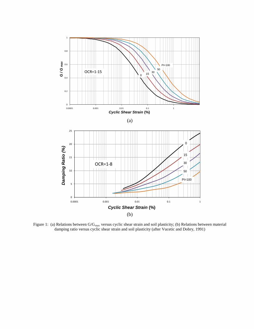
the resulting shear modulus is called Gmax. In the event of an earthquake, the cyclic shear strain amplitude
increases, and the shear strain modulus (Gsec) and damping ratio (λ), which both vary with the cyclic shear
strain amplitude, change relatively. These nonlinearities in soil stiffness and damping ratio (Hysteretic
damping) for cohesive soils were elucidated by Vucetic and Dobry (1991) as two ready to use curves. Their
represented relation between G/Gmax and damping ratio versus cyclic shear strain ( cγ ) and soil plasticity (PI)
for normally and over consolidated cohesionless soils are illustrated in Figure 1.
Based on the review of a number of available cyclic loading results, they concluded that the soil plasticity
index (PI) is the main factor controlling the modulus reduction G/Gmax and cyclic shear strain relationship as
well as, material damping ratio (λ) versus cyclic shear strain curve, for a wide variety of cohesive soils. As
the soil plasticity index increases, G/Gmax increases and damping ratio decreases. This is true for both
normally and over consolidated soils.
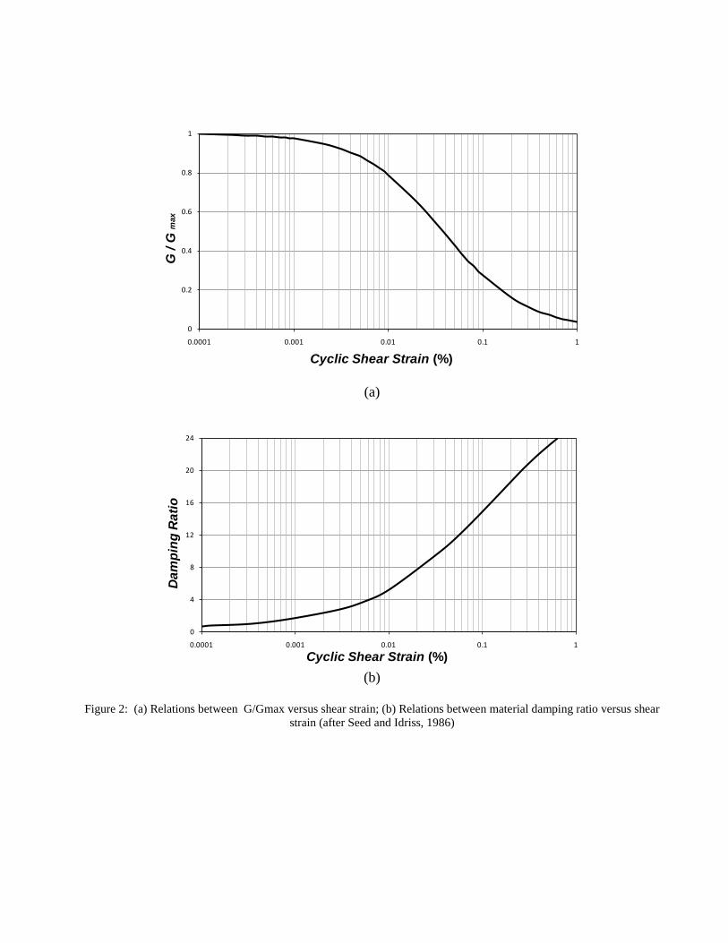
For cohesionless soils, Seed and Idriss (1986) represented the modulus reduction G/Gmax and cyclic shear
strain curve as well as material damping ratio versus cyclic shear strain curve, for a wide variety of
cohesionless soils (Fig. 2). Based on the results, they concluded that damping ratio for gravel is very similar

to damping ratio for sand but the slope of sand curve is a little steeper than the curve for gravel. In
cohesionless soils, as the cyclic shear strain increases, G/Gmax decreases and damping ratio increases.
Using fully nonlinear method for dynamic analysis, enable us to employ these charts directly in the model
and take soil nonlinearity into account in an accurate and realistic way.
CHARASTRISTIC OF THE EMPLOYED STRUCTURAL MODEL In this study, a ten storey concrete moment resisting building frame resting on a shallow foundation (4
meters in width and 12 meters in length) is selected in conjunction with the three mentioned soil types.
Structural sections are designed according to AS3600:2001 (Australian Standard for Concrete Structures)
after undertaking dynamic time history analysis, once based on elastic behaviour of the structural system, and
the next time considering inelastic behaviour under influence of four different earthquake ground motions, as
a fixed base model. The specified compressive strength of concrete is assumed to be, cf ′ = 32 MPa, the
specified yield strength of steel rebar, yf = 400MPa, and the concrete density, cγ = 25kN/m3.
The modulus of elasticity of concrete was calculated according to clause 6.1.2 of AS3600:2001 (Australian
Standard for Concrete Structures). Performance level of the structural model is considered as ‘life safe’ level in
this for elastic and inelastic design indicating the maximum inter-storey drifts of the model being less than 1.5%.
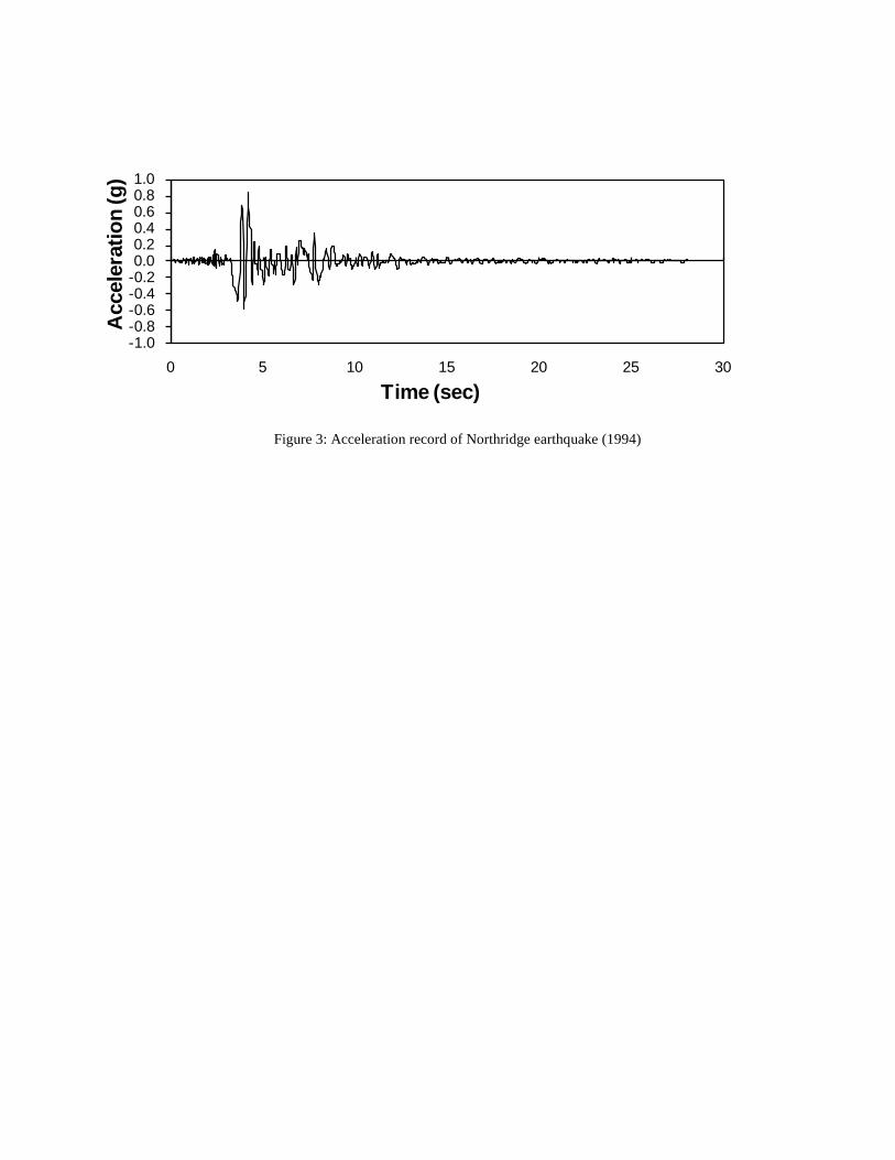
The characteristics of the earthquake ground motions are tabulated in Table 2 and Figures 3-6. It is assumed that
the earthquake ground motions are bedrock records.
NUMERICAL SIMULATION OF SOIL - STRUCTURE SYSTEM In this study, fully nonlinear time history dynamic analysis has been employed using FLAC 2D to define
elastic and inelastic seismic response of the concrete moment resisting frame under the influence of SSI.
Dynamic analyses are carried out for two different systems: (i) fixed-base structure on the rigid ground
(Figure 7), and (ii) frames considering subsoil (Figure 8) using direct method of soil-structure interaction
analysis as the flexible base model. The analyses are undertaken for two different cases by including elastic
and inelastic behaviour of the structural system.

The following aspects have been incorporated in the dynamic time history analysis of the study:
Nonlinear behaviour of the subsoil including material nonlinearity (relationship between soil stiffness
and material damping ratio versus cyclic shear strain proposed by Vucetic and Dobry (1991) and
Seed and Idriss (1986) and geometric nonlinearity (large strains);
Elastic and inelastic behaviour of the structural system (Elastic-perfectly plastic behaviour of
concrete elements according to ATC-40, 1996) and geometric nonlinearity of the structure (large
displacements); and
Cracked sections for the reinforced concrete sections by multiplying moment of inertial of the
uncracked sections by cracked section coefficients (0.35Ig for beams and 0.70Ig for columns)
according to Section 10.11.1 of ACI318.2002.
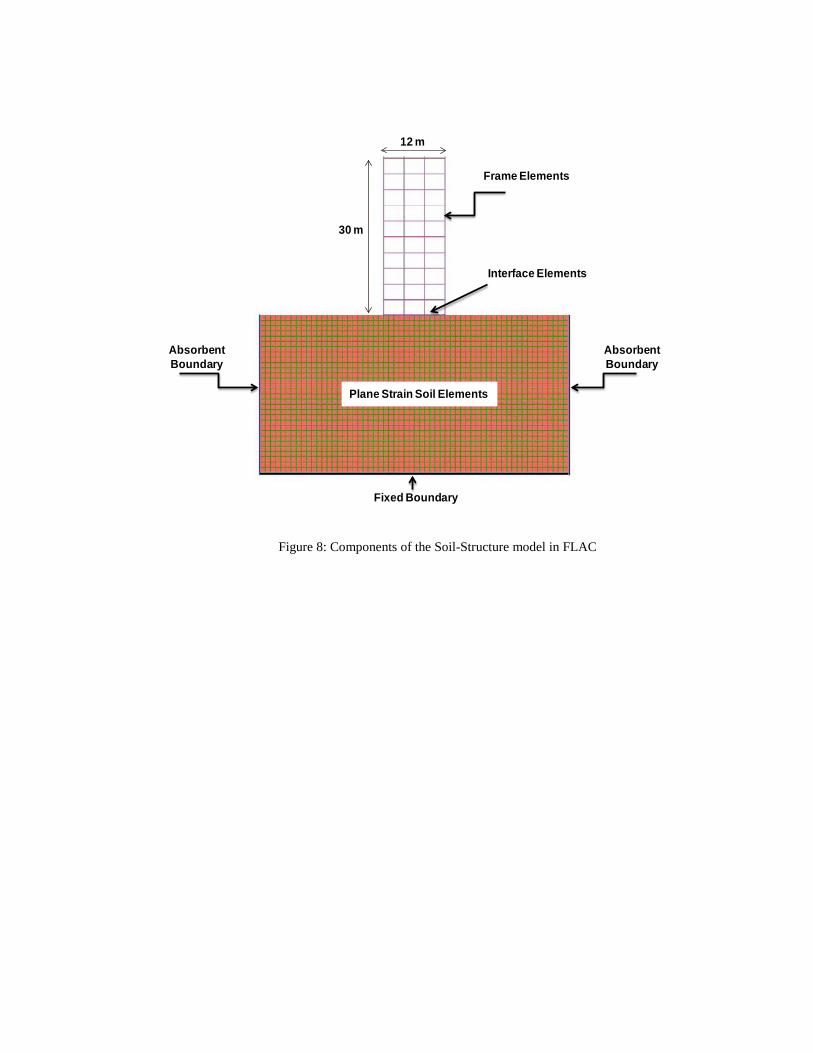
The soil-structure model (Figure 8) comprises beam elements to model beams, columns, and strip foundation,
two dimensional plane-strain grid elements to model soil medium, fixed boundaries to model the bed rock,
absorbent boundaries (viscous boundaries) to avoid reflective waves produced by soil lateral boundaries, and
interface elements to simulate frictional contact and probable slip due to seismic excitation. According to
Rayhani and Naggar (2008), horizontal distance between soil boundaries is assumed to be five times the
structure width, and the bedrock depth is assumed to be 30 m. The strip reinforced concrete foundation is 4
meters in width and 12 meters in length and 1 meter deep. As it is a plane strain problem, strip foundation
width has been taken into account to calculate moment of inertia of the concrete element only. The foundation
facing zone in numerical simulations is separated from the adjacent soil zone by interface elements. The
interfaces between the foundation and soil is represented as a normal and shear stiffness between two planes
contacting each other and is modelled as linear spring–slider systems, with interface shear strength defined by
the Mohr–Coulomb failure criterion. The relative interface movement is controlled by interface stiffness
values in the normal and tangential directions. Based on recommended formula estimates for maximum

interface stiffness values given by Itasca Consulting Group (2008), normal and tangential spring stiffness
values are set to ten times the equivalent stiffness of the neighbouring zone.
Four different earthquake ground motions (Table 2 and Figures 3-6) are applied to both systems in two
different ways. In the case of modelling soil and structure simultaneously using direct method (flexible base),
the earthquake records are applied to the combination of soil and structure directly at the bed rock level, while
for modelling the structure as the fixed base (without soil), the earthquake records are applied to the base of
the structural models.
RESULTS AND DISCUSSION The results of the elastic and inelastic analyses including the base shear and the inter-storey drifts are determined
and compared for the fixed-base and flexible-base models resting on the three different types of soil, so as to
identify the effects of subsoil rigidity on elastic and inelastic seismic response of moment resisting frames and
their performance levels.
According to the results summarised in Table 3 and 4, the ratios of base shear of the flexible-base models (V~ )
to that of fixed-base (V) in all models are less than one for both elastic and inelastic cases. However, these ratios
are larger and closer to unity for inelastic analysis in comparison with elastic analysis. Therefore, base shear of
the structures modelled with soil as flexible-base are always less than the base shear of structures modelled as
fixed base. These results have good conformity to Section 5.6.2 of NEHRP-2003 regulations as in this section
reduction of base shear due to SSI is predicted.
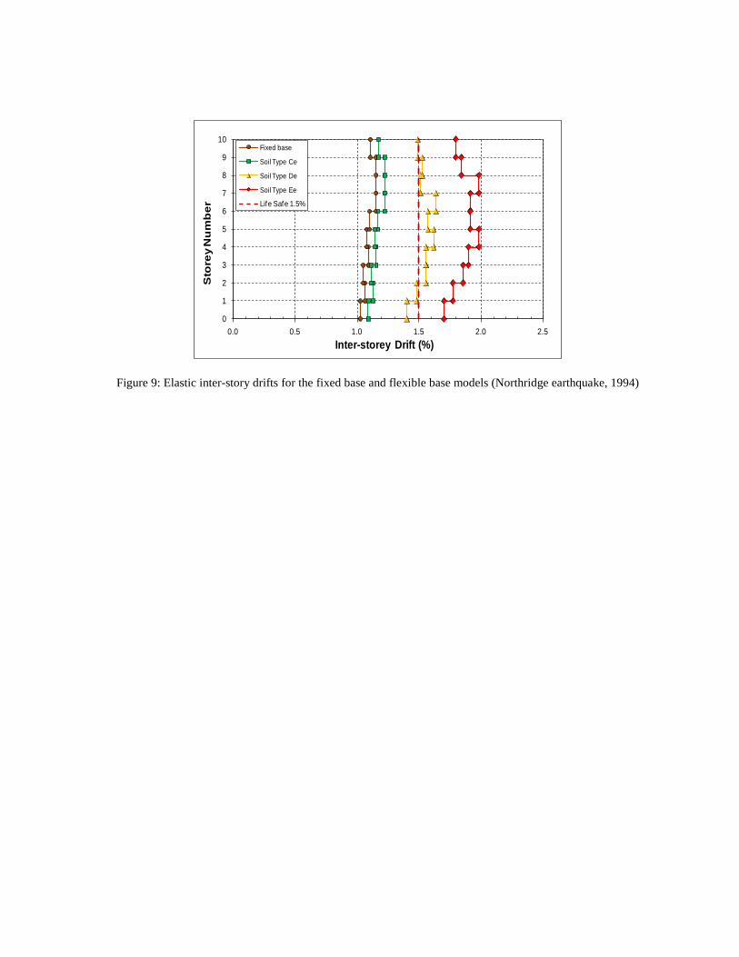
Comparing the inter-storey drifts of fixed-base and flexible-base models resting on soil classes Ce, De, and
Ee for elastic case (Figures 9-12) and inelastic case (Figures 13-16) respectively, it is observed that the
inter-storey drifts of the flexible base model resting on soil class Ce do not differ much from that of the
fixed-base model for both cases. As a result, the performance level of the model resting on soil class Ce
remains in life safe level.

However, for both elastic and inelastic cases, inter-storey drifts of the flexible base model resting on soil
class De increases to more than 1.5% by incorporating dynamic SSI. Thus, performance level of the
model resting on soil De changes from life safe level to near collapse level. The situation is more critical
for the model on soil class Ee as the performance level of the model substantially increases from life safe
to near collapse. Such a significance change in the inter-storey drifts and subsequently performance level
of the model resting on soils De and Ee (especially for soil class Ee) is absolutely dangerous and safety
threatening. Based on the mentioned results, it is found that by decreasing the dynamic properties of the
subsoil such as shear wave velocity (Vs) and shear modulus (Gmax), maximum lateral deflections of the
moment resisting building frames increase significantly.
The spectral displacement changes considerably with changes in natural period due to SSI effects for both
elastic and inelastic cases. Therefore, such increases in the natural period may considerably alter the response
of the building frames under seismic excitation. This is due to the fact that the natural period lies in the long
period region of the response spectrum curve because of the natural period lengthening for such systems.
Hence, the displacement response tends to increase. Therefore, performance level of the structure, especially
for the structures analysed and designed based on the elastic method, changes from life safe to near collapse
or total collapse. The risk for the structures analysed and designed based on the inelastic analysis is a bit
smaller but the structures are still vulnerable to the change of the performance level. Thus, design engineers
need to precisely take the effects of dynamic SSI into account in their design especially for construction
projects on soft soils.
CONCLUSIONS AND RECOMMENDATIONS In this study, regarding the importance of subsoil dynamic properties on elastic and inelastic behaviour of
mid-rise concrete moment resisting building frames under influence of soil-structure interaction, numerical
investigations have been conducted for the 10 storey concrete moment resisting building frame resting on soil
classes Ce, De and Ee. According to the results, it is observed that base shear of the structures modelled with
soil as flexible-base are generally less than the base shear of the structures modelled as fixed-base for both

elastic and inelastic cases. However, in inelastic case the base shear ratios of fixed-base to flexible-base are
closer to unity in comparison with the elastic case.
It is also found that performance level of the model resting on soil class Ce does not change substantially and
remains in life safe level. Therefore, the effects of soil-structure interaction for elastic and inelastic seismic
design of moment resisting buildings founded on soil type Ce is negligible, while performance level of the
model resting on soil classes De and Ee substantially increase (especially for soil class Ee) from life safe to
near collapse. As a result, considering SSI effects in elastic and inelastic seismic design of concrete moment
resisting building frame resting on soil classes De and Ee is essential. Generally, by decreasing the dynamic
properties of the subsoil such as shear wave velocity and shear modulus, base shear ratios decrease while
inter-storey drifts of the moment resisting building frames increase relatively. In brief, the conventional
elastic and inelastic design procedure excluding SSI is not adequate to guarantee the structural safety for
moment resisting building frames resting on soil classes De and Ee.
As most of the seismic design codes around the globe do not address the soil-structure interaction (SSI)
explicitly, considering SSI effects in seismic design as a distinguished part of these standards is highly
recommended. It is also suggested to engineering companies working in regions located in high earthquake
risk zones, to consider SSI influences in dynamic analysis and design of moment resisting building frames on
soft soils to ensure the designs are safe and reliable.
REFERENCES AS1170.4 .2007. Earthquake action in Australia. Standards Australia, NSW, Australia.
AS3600. 2001. Concrete Structures. Standards Australia, NSW, Australia.
ATC-40. 1996. Seismic Evaluation and Retrofit of Concrete Buildings. Applied Technology Council, Seismic Safety
Commission, State of California.
Byrne, P. M., and Wijewickreme, D. 2006. Liquefaction Resistance and Post-Liquefaction Response of Soils for Seismic
Design of Buildings in Greater Vancouver, 59th Canadian Geotechnical Conference, 1267-1278.
Dutta, C.H., Bhattacharya, K., and Roy, R. 2004. Response of low-rise buildings under seismic ground excitation
incorporating soil-structure interaction, Soil Dynamic and Earthquake Engineering, 24(9), 893-914.
Itasca Consulting Group, Inc. Itasca. 2008. FLAC2D: Fast Lagrangian Analysis of Continua, version 6.0. User’s manual,
Minneapolis.
Faleiro, J., Oller S., and Barbat, A.H. (2008). Plastic–damage seismic model for reinforced concrete frames, Journal of
Computers and Structures 86 581–597.
FEMA 273/274. 1997. NEHRP Guidelines for the Seismic Rehabilitation for Buildings. Emergency Management
Agency, Washington, D.C.
Galal, K. and Naimi, M. 2008.Effect of conditions on the Response of Reinforced Concrete Tall Structures to Near Fault
Earthquakes, Struct.Design tall Spec.build, 17(3), 541-562.
Gazetas, G. and Mylonakis, G. 1998. Seismic soil-structure interaction: new evidence and emerging issues, Geotechnical
Earthquake Engineering and Soil Dynamics, 10(2), 1119-1174.
Horvath, J.S. and Colasanti, R.J. 2011. Practical Subgrade Model for Improved Soil-Structure Interaction Analysis:
Model Development, International Journal of Geomechanics 11(1), 59–64.
NEHRP. 2003. Recommended Provisions for Seismic Regulation for New Buildings and Other Structures (2003), Part 2:
Commentary FEMA 303, Federal Emergency Management Agency, Washington, DC, USA.
Mejia, L. H., and E. M. Dawson. (2006). “Earthquake Deconvolution for FLAC”, Proceedings of the 4th International
FLAC Symposium, Madrid, Spain, pp. 211-219.
Rahvar. (2005). “Geotechnical and Geophysical Investigations and Foundation Design Report of Musalla Construction Site
in Tehran”, P. O. Rahvar Pty Ltd., Vol. 1, Tehran, 1-64.

Rahvar. (2006a). “Geotechnical Investigations and Foundation Design Report of Kooh-e-Noor Commercial Building”, P.
O. Rahvar Pty Ltd., Final Report, Tehran, Iran, 1-69.
Rahvar. (2006b). “Geotechnical Investigations and Foundation Design Report of Mahshahr Train Station”, P. O. Rahvar
Pty Ltd., Iran Railways Authority, Mahshahr, Iran, 1-42.
Rayhani, M.H. and El Naggar, M.H. 2008. Numerical Modelling of Seismic Response of Rigid Foundation on Soft Soil,
International Journal of Geomechanics 8(6), 336-346.
Seed, H. B., and Idriss, I.M., 1969. Influence of Soil Conditions on Ground Motion During Earthquakes, J. Soil Mech.
Found. Div. ASCE, 95(2), 99-137.
Tabatabaiefar, H.R., Massumi, A. 2010. A simplified Method to Determine Seismic Responses of Reinforced Concrete
Moment Resisting Building Frames under Influence of Soil–Structure Interaction, Soil Dynamics and Earthquake
Engineering, 30(11), 1259-1267, Elsevier Ltd., (ISI).
Veletsos, A.S. and Meek, J. W. 1974. Dynamic Behaviour of Building-Foundation system, Journal of Earthquake
Engineering and Structural Dynamics, 3(2), 121-38.
Vucetic, M. and Dobry, R. 1991. Effects of Soil Plasticity on Cyclic Response, Journal of Geotechnical
Engineering, 117(1), 89-10.
Vision 2000 Committee. 1995. Performance Based Seismic Engineering of Buildings. Structural Engineers
Association of California (SEAOC), Sacramento, CA.

LIST OF FIGURES
Figure 1: (a) Relations between G/Gmax versus cyclic shear strain and soil plasticity; (b) Relations between
material damping ratio versus cyclic shear strain and soil plasticity (after Vucetic and Dobry, 1991)
Figure 2: (a) Relations between G/Gmax versus shear strain; (b) Relations between material damping ratio
versus shear strain (after Seed and Idriss, 1986)
Figure 3: Acceleration record of Northridge earthquake (1994)
Figure 4: Acceleration record of Kobe earthquake (1995)
Figure 5: Acceleration record of El-Centro earthquake (1940)
Figure 6: Acceleration record of Hachinohe earthquake (1968)
Figure 7: Fixed-base model
Figure 8: Components of the Soil-Structure model in FLAC
Figure 9: Elastic inter-story drifts for the fixed base and flexible base models (Northridge earthquake, 1994)
Figure 10: Elastic inter-story drifts for the fixed base and flexible base models (Kobe earthquake, 1995)
Figure 11: Elastic inter-story drifts for the fixed base and flexible base models (El Centro earthquake, 1940)
Figure 12: Elastic inter-story drifts for the fixed base and flexible base models (Hachinohe earthquake, 1968)
Figure 13: Inelastic inter-story drifts for the fixed base and flexible base models (Northridge earthquake,
1994)
Figure 14: Inelastic inter-story drifts for the fixed base and flexible base models (Kobe earthquake, 1995)
Figure 15: Inelastic inter-story drifts for the fixed base and flexible base models (El Centro earthquake, 1940)
Figure 16: Inelastic inter-story drifts for the fixed base and flexible base models (Hachinohe earthquake,
1968)
Cyclic Shear Strain (%)
0
0.2
0.4
0.6
0.8
1
0.0001 0.001 0.01 0.1 1
G /
G m
ax
OCR=1-150 15 30
50PI=100
(a)
Cyclic Shear Strain (%)
Dam
ping
Rat
io (%
)
0
5
10
15
20
25
0.0001 0.001 0.01 0.1 1
0
15
30
50
PI=100
OCR=1-8
(b)
Figure 1: (a) Relations between G/Gmax versus cyclic shear strain and soil plasticity; (b) Relations between material
damping ratio versus cyclic shear strain and soil plasticity (after Vucetic and Dobry, 1991)
Cyclic Shear Strain (%)
G /
G m
ax
0
0.2
0.4
0.6
0.8
1
0.0001 0.001 0.01 0.1 1
(a)
Cyclic Shear Strain (%)
Dam
ping
Rat
io
0
4
8
12
16
20
24
0.0001 0.001 0.01 0.1 1
(b)
Figure 2: (a) Relations between G/Gmax versus shear strain; (b) Relations between material damping ratio versus shear
strain (after Seed and Idriss, 1986)
-1.0-0.8-0.6-0.4-0.20.00.20.40.60.81.0
0 5 10 15 20 25 30
Acc
eler
atio
n (g
)
Time (sec)
Figure 3: Acceleration record of Northridge earthquake (1994)

-1.0-0.8-0.6-0.4-0.20.00.20.40.60.81.0
0 10 20 30 40 50 60
Acc
eler
atio
n (g
)
Time (sec)
Figure 4: Acceleration record of Kobe earthquake (1995)

-0.4-0.3-0.2-0.10.00.10.20.30.4
0 10 20 30 40 50 60
Acc
eler
atio
n (g
)
Time (sec)
Figure 5: Acceleration record of El-Centro earthquake (1940)

-0.4-0.3-0.2-0.10.00.10.20.30.4
0 5 10 15 20 25 30 35 40
Acc
eler
atio
n (g
)
Time (sec)
Figure 6: Acceleration record of Hachinohe earthquake (1968)

30 m
12 m
Figure 7: Fixed-base model
Frame ElementsFrame Elements
Interface Elements
Absorbent Boundary
Plane Strain Soil Elements
Fixed Boundary
Absorbent Boundary
12 m
30 m
Figure 8: Components of the Soil-Structure model in FLAC
0
1
2
3
4
5
6
7
8
9
10
0.0 0.5 1.0 1.5 2.0 2.5
Sto
rey
Nu
mb
er
Inter-storey Drift (%)
Fixed base
Soil Type Ce
Soil Type De
Soil Type Ee
Life Safe 1.5%
Figure 9: Elastic inter-story drifts for the fixed base and flexible base models (Northridge earthquake, 1994)

0
1
2
3
4
5
6
7
8
9
10
0.0 0.5 1.0 1.5 2.0 2.5
Sto
rey
Nu
mb
er
Inter-storey Drift (%)
Fixed base
Soil Type Ce
Soil Type De
Soil Type Ee
Life Safe 1.5%
Figure 10: Elastic inter-story drifts for the fixed base and flexible base models (Kobe earthquake, 1995)

0
1
2
3
4
5
6
7
8
9
10
0.0 0.5 1.0 1.5 2.0 2.5
Sto
rey
Nu
mb
er
Inter-storey Drift (%)
Fixed base
Soil Type Ce
Soil Type De
Soil Type Ee
Life Safe 1.5%
Figure 11: Elastic inter-story drifts for the fixed base and flexible base models (El Centro earthquake, 1940)

0
1
2
3
4
5
6
7
8
9
10
0.0 0.5 1.0 1.5 2.0 2.5
Sto
rey
Nu
mb
er
Inter-storey Drift (%)
Fixed base
Soil Type Ce
Soil Type De
Soil Type Ee
Life Safe 1.5%
Figure 12: Elastic inter-story drifts for the fixed base and flexible base models (Hachinohe earthquake, 1968)

0
1
2
3
4
5
6
7
8
9
10
0.0 0.5 1.0 1.5 2.0 2.5
Sto
rey
Nu
mb
er
Inter-storey Drift (%)
Fixed base
Soil Type Ce
Soil Type De
Soil Type Ee
Life Safe (1.5%)
Figure 13: Inelastic inter-story drifts for the fixed base and flexible base models (Northridge earthquake, 1994)

0
1
2
3
4
5
6
7
8
9
10
0.0 0.5 1.0 1.5 2.0 2.5
Sto
rey
Nu
mb
er
Inter-storey Drift (%)
Fixed base
Soil Type Ce
Soil Type De
Soil Type Ee
Life Safe (1.5%)
Figure 14: Inelastic inter-story drifts for the fixed base and flexible base models (Kobe earthquake, 1995)

0
1
2
3
4
5
6
7
8
9
10
0.0 0.5 1.0 1.5 2.0 2.5
Sto
rey
Nu
mb
er
Inter-storey Drift (%)
Fixed base
Soil Type Ce
Soil Type De
Soil Type Ee
Life Safe (1.5%)
Figure 15: Inelastic inter-story drifts for the fixed base and flexible base models (El Centro earthquake, 1940)

0
1
2
3
4
5
6
7
8
9
10
0.0 0.5 1.0 1.5 2.0 2.5
Sto
rey
Nu
mb
er
Inter-storey Drift (%)
Fixed base
Soil Type Ce
Soil Type De
Soil Type Ee
Life Safe (1.5%)
Figure 16: Inelastic inter-story drifts for the fixed base and flexible base models (Hachinohe earthquake, 1968)

LIST OF TABLES Table 1: Geotechnical characteristics of the utilised soils in this study
Table 2: Earthquake ground motions used in this study
Table 3: Base shear ratio of flexible-base to fixed-base models from elastic analyses
Table 4: Base shear ratio of flexible-base to fixed-base from inelastic analyses

Table 1: Geotechnical characteristics of the utilised soils in this study
Soil Type (AS1170)
Shear wave
velocity Vs
(m/s)
Unified classification
Shear Modulus
Gmax (kPa)
Poisson Ratio SPT
Plastic Index (PI)
c′ (kPa)
φ′ (Degree) Reference
Ce 600 GM 623,409 0.28 N>50 - 5 40 Rahvar (2005)
De 320 CL 177,304 0.39 30 20 20 19 Rahvar (2006a)
Ee 150 CL 33,100 0.40 6 15 20 12 Rahvar (2006b)

Table 2: Earthquake ground motions used in this study
Earthquake Country Year PGA (g) Mw (R)
Northridge USA 1994 0.843 6.7 Kobe Japan 1995 0.833 6.8 El Centro USA 1940 0.349 6.9 Hachinohe Japan 1968 0.229 7.5
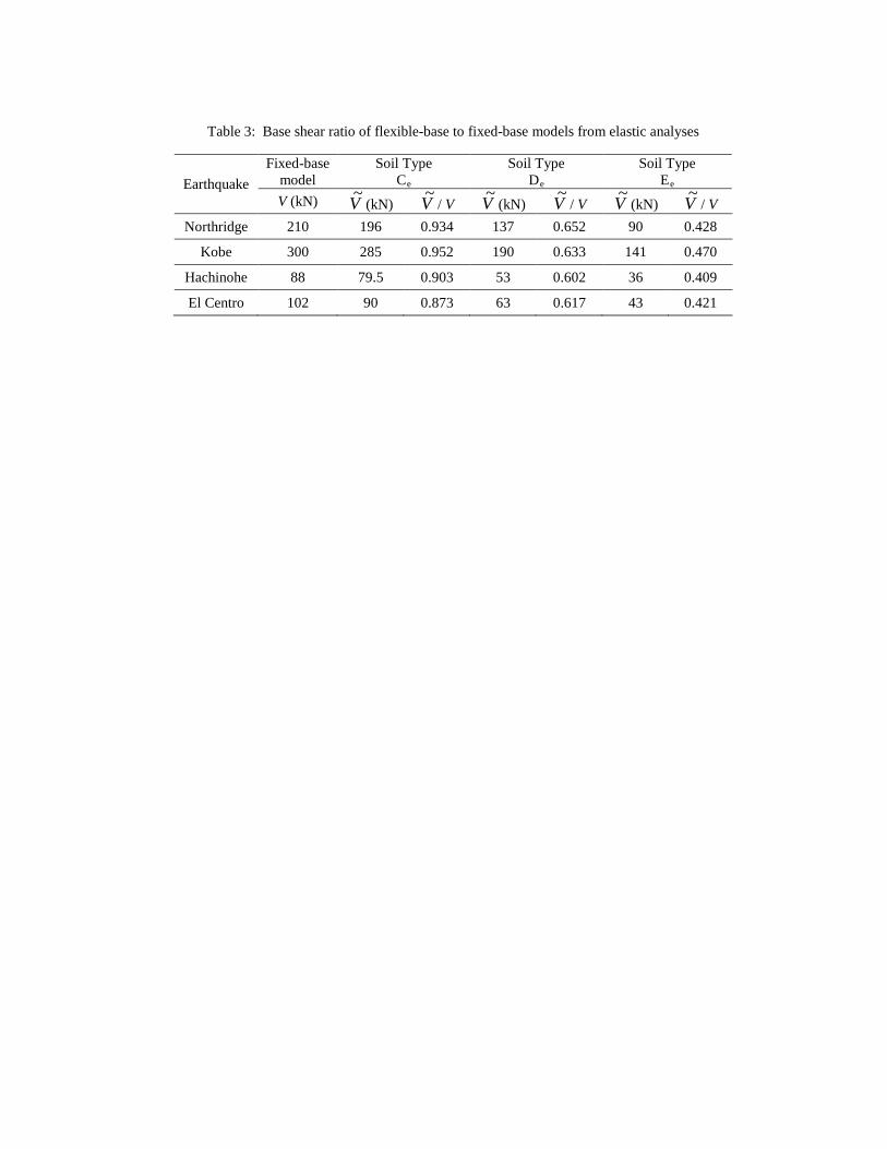
Table 3: Base shear ratio of flexible-base to fixed-base models from elastic analyses
Earthquake Fixed-base
model Soil Type
Ce Soil Type
De Soil Type
Ee V (kN) V~ (kN) V~ / V V~ (kN) V~ / V V~ (kN) V~ / V
Northridge 210 196 0.934 137 0.652 90 0.428
Kobe 300 285 0.952 190 0.633 141 0.470
Hachinohe 88 79.5 0.903 53 0.602 36 0.409
El Centro 102 90 0.873 63 0.617 43 0.421

Table 4: Base shear ratio of flexible-base to fixed-base from inelastic analyses
Earthquake Fixed-base
model Soil Type
Ce Soil Type
De Soil Type
Ee V (kN) V~ (kN) V~ / V V~ (kN) V~ / V V~ (kN) V~ / V
Northridge 140 132 0.942 109 0.778 77 0.550
Kobe 186 180 0.967 144 0.774 110 0.591
Hachinohe 60 57 0.950 47 0.783 28 0.466
El Centro 68 63 0.926 49 0.721 31 0.455