seismic bracing for hvac equipment - …docshare01.docshare.tips/files/27175/271755948.pdf ·...
TRANSCRIPT
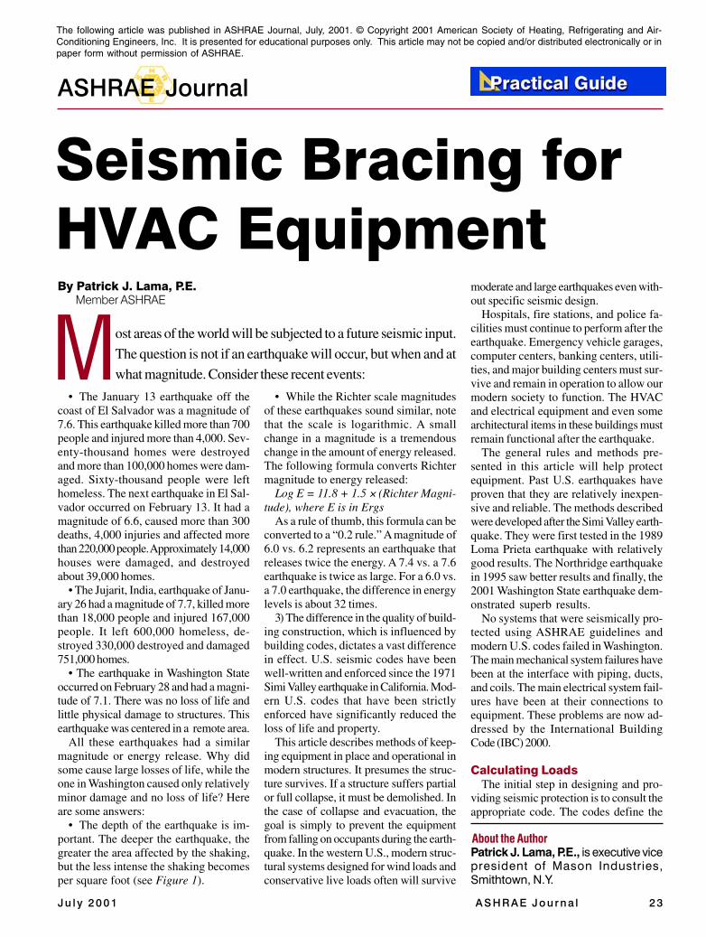
J u l y 2 0 0 1 A S H R A E J o u r n a l 2 3
ASHRAE Journal
M
Seismic Bracing forHVAC Equipment
About the Author
By Patrick J. Lama, P.E.Member ASHRAE
ost areas of the world will be subjected to a future seismic input.
The question is not if an earthquake will occur, but when and at
what magnitude. Consider these recent events:
• The January 13 earthquake off thecoast of El Salvador was a magnitude of7.6. This earthquake killed more than 700people and injured more than 4,000. Sev-enty-thousand homes were destroyedand more than 100,000 homes were dam-aged. Sixty-thousand people were lefthomeless. The next earthquake in El Sal-vador occurred on February 13. It had amagnitude of 6.6, caused more than 300deaths, 4,000 injuries and affected morethan 220,000 people. Approximately 14,000houses were damaged, and destroyedabout 39,000 homes.
• The Jujarit, India, earthquake of Janu-ary 26 had a magnitude of 7.7, killed morethan 18,000 people and injured 167,000people. It left 600,000 homeless, de-stroyed 330,000 destroyed and damaged751,000 homes.
• The earthquake in Washington Stateoccurred on February 28 and had a magni-tude of 7.1. There was no loss of life andlittle physical damage to structures. Thisearthquake was centered in a remote area.
All these earthquakes had a similarmagnitude or energy release. Why didsome cause large losses of life, while theone in Washington caused only relativelyminor damage and no loss of life? Hereare some answers:
• The depth of the earthquake is im-portant. The deeper the earthquake, thegreater the area affected by the shaking,but the less intense the shaking becomesper square foot (see Figure 1).
• While the Richter scale magnitudesof these earthquakes sound similar, notethat the scale is logarithmic. A smallchange in a magnitude is a tremendouschange in the amount of energy released.The following formula converts Richtermagnitude to energy released:
Log E = 11.8 + 1.5 × (Richter Magni-tude), where E is in Ergs
As a rule of thumb, this formula can beconverted to a “0.2 rule.” A magnitude of6.0 vs. 6.2 represents an earthquake thatreleases twice the energy. A 7.4 vs. a 7.6earthquake is twice as large. For a 6.0 vs.a 7.0 earthquake, the difference in energylevels is about 32 times.
3) The difference in the quality of build-ing construction, which is influenced bybuilding codes, dictates a vast differencein effect. U.S. seismic codes have beenwell-written and enforced since the 1971Simi Valley earthquake in California. Mod-ern U.S. codes that have been strictlyenforced have significantly reduced theloss of life and property.
This article describes methods of keep-ing equipment in place and operational inmodern structures. It presumes the struc-ture survives. If a structure suffers partialor full collapse, it must be demolished. Inthe case of collapse and evacuation, thegoal is simply to prevent the equipmentfrom falling on occupants during the earth-quake. In the western U.S., modern struc-tural systems designed for wind loads andconservative live loads often will survive
moderate and large earthquakes even with-out specific seismic design.
Hospitals, fire stations, and police fa-cilities must continue to perform after theearthquake. Emergency vehicle garages,computer centers, banking centers, utili-ties, and major building centers must sur-vive and remain in operation to allow ourmodern society to function. The HVACand electrical equipment and even somearchitectural items in these buildings mustremain functional after the earthquake.
The general rules and methods pre-sented in this article will help protectequipment. Past U.S. earthquakes haveproven that they are relatively inexpen-sive and reliable. The methods describedwere developed after the Simi Valley earth-quake. They were first tested in the 1989Loma Prieta earthquake with relativelygood results. The Northridge earthquakein 1995 saw better results and finally, the2001 Washington State earthquake dem-onstrated superb results.
No systems that were seismically pro-tected using ASHRAE guidelines andmodern U.S. codes failed in Washington.The main mechanical system failures havebeen at the interface with piping, ducts,and coils. The main electrical system fail-ures have been at their connections toequipment. These problems are now ad-dressed by the International BuildingCode (IBC) 2000.
Calculating LoadsThe initial step in designing and pro-
viding seismic protection is to consult theappropriate code. The codes define the
Patrick J. Lama, P.E., is executive vicepresident of Mason Industries,Smithtown, N.Y.
The following article was published in ASHRAE Journal, July, 2001. © Copyright 2001 American Society of Heating, Refrigerating and Air-Conditioning Engineers, Inc. It is presented for educational purposes only. This article may not be copied and/or distributed electronically or inpaper form without permission of ASHRAE.
2 4 ASHRAE Journa l www.ash rae jou rna l .o rg J u l y 2 0 0 1
ASHRAE Journal
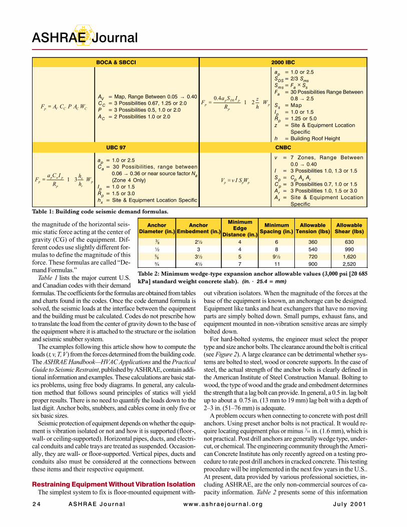
the magnitude of the horizontal seis-mic static force acting at the center ofgravity (CG) of the equipment. Dif-ferent codes use slightly different for-mulas to define the magnitude of thisforce. These formulas are called “De-mand Formulas.”
Table 1 lists the major current U.S.and Canadian codes with their demandformulas. The coefficients for the formulas are obtained from tablesand charts found in the codes. Once the code demand formula issolved, the seismic loads at the interface between the equipmentand the building must be calculated. Codes do not prescribe howto translate the load from the center of gravity down to the base ofthe equipment where it is attached to the structure or the isolationand seismic snubber system.
The examples following this article show how to compute theloads (t, v, T, V) from the forces determined from the building code.The ASHRAE Handbook—HVAC Applications and the PracticalGuide to Seismic Restraint, published by ASHRAE, contain addi-tional information and examples. These calculations are basic stat-ics problems, using free body diagrams. In general, any calcula-tion method that follows sound principles of statics will yieldproper results. There is no need to quantify the loads down to thelast digit. Anchor bolts, snubbers, and cables come in only five orsix basic sizes.
Seismic protection of equipment depends on whether the equip-ment is vibration isolated or not and how it is supported (floor-,wall- or ceiling-supported). Horizontal pipes, ducts, and electri-cal conduits and cable trays are treated as suspended. Occasion-ally, they are wall- or floor-supported. Vertical pipes, ducts andconduits also must be considered at the connections betweenthese items and their respective equipment.
Restraining Equipment Without Vibration IsolationThe simplest system to fix is floor-mounted equipment with-
out vibration isolators. When the magnitude of the forces at thebase of the equipment is known, an anchorage can be designed.Equipment like tanks and heat exchangers that have no movingparts are simply bolted down. Small pumps, exhaust fans, andequipment mounted in non-vibration sensitive areas are simplybolted down.
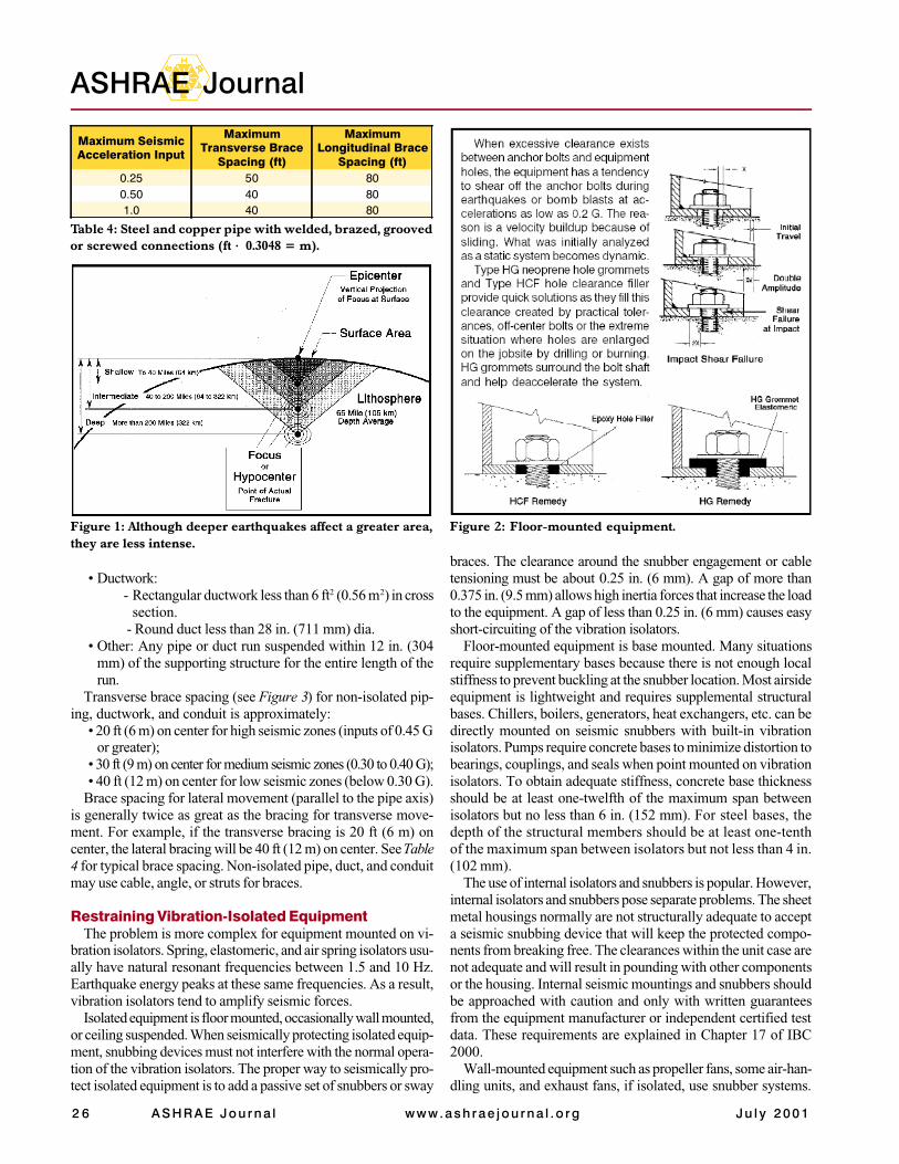
For hard-bolted systems, the engineer must select the propertype and size anchor bolts. The clearance around the bolt is critical(see Figure 2). A large clearance can be detrimental whether sys-tems are bolted to steel, wood or concrete supports. In the case ofsteel, the actual strength of the anchor bolts is clearly defined inthe American Institute of Steel Construction Manual. Bolting towood, the type of wood and the grade and embedment determinesthe strength that a lag bolt can provide. In general, a 0.5 in. lag boltup to about a 0.75 in. (13 mm to 19 mm) lag bolt with a depth of2–3 in. (51–76 mm) is adequate.
A problem occurs when connecting to concrete with post drillanchors. Using preset anchor bolts is not practical. It would re-quire locating equipment plus or minus 16
1 in. (1.6 mm), which isnot practical. Post drill anchors are generally wedge type, under-cut, or chemical. The engineering community through the Ameri-can Concrete Institute has only recently agreed on a testing pro-cedure to rate post drill anchors in cracked concrete. This testingprocedure will be implemented in the next few years in the U.S..At present, data provided by various professional societies, in-cluding ASHRAE, are the only non-commercial sources of ca-pacity information. Table 2 presents some of this information
AnchorDiameter (in.)
AnchorEmbedment (in.)
MinimumEdge
Distance (in.)
MinimumSpacing (in.)
AllowableTension (lbs)
AllowableShear (lbs)
2½ 4 6 360 630½ 3 4 8 540 990
3½ 5 9½ 720 1,620¾ 4½ 7 11 900 2,520
83
85
Table 2: Minimum wedge-type expansion anchor allowable values (3,000 psi [20 685kPa] standard weight concrete slab). (in. × 25.4 = mm)
BOCA & SBCCI 2000 IBC
UBC 97 CNBC
ap = 1.0 or 2.5Ca = 30 Possibilities, range between
0.06 → 0.36 or near source factor Na(Zone 4 Only)
Ip = 1.0 or 1.5Rp = 1.5 or 3.0hx = Site & Equipment Location Specific
AV = Map, Range Between 0.05 → 0.40CC = 3 Possibilities 0.67, 1.25 or 2.0P = 3 Possibilities 0.5, 1.0 or 2.0AC = 2 Possibilities 1.0 or 2.0
pr
x
p
papp W
hh
R
ICaF
+= 31
CCCVp WAPCAF = pp
pDSpp W
hz
R
ISaF 21
4.0
+=
ppp WSIvV =
ap = 1.0 or 2.5SDS = 2/3 SmsSms = Fa × SsFa = 30 Possibilities Range Between
0.8 → 2.5Ss = MapIp = 1.0 or 1.5Rp = 1.25 or 5.0z = Site & Equipment Location
Specifich = Building Roof Height
v = 7 Zones, Range Between0.0 → 0.40
I = 3 Possibilities 1.0, 1.3 or 1.5Sp = Cp Ax ArCp = 3 Possibilities 0.7, 1.0 or 1.5A r = 3 Possibilities 1.0, 1.5 or 3.0Ax = Site & Equipment Location
SpecificTable 1: Building code seismic demand formulas.
J u l y 2 0 0 1 ASHRAE Journa l 2 5
Seismic
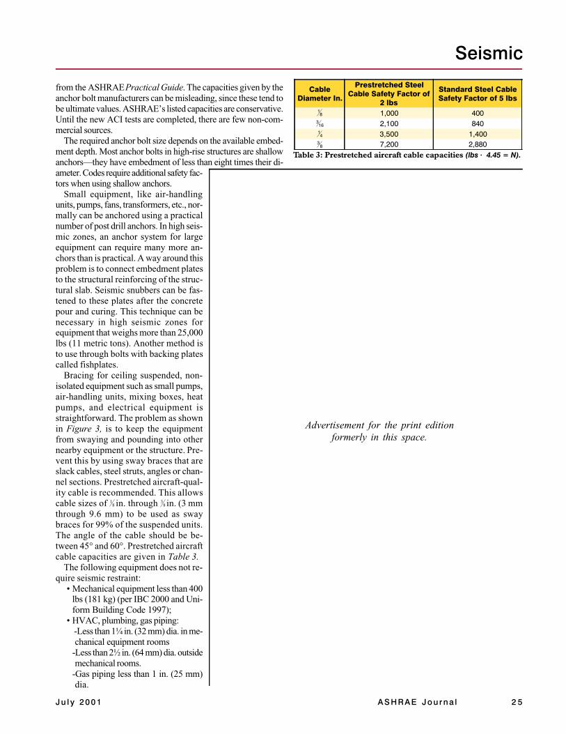
from the ASHRAE Practical Guide. The capacities given by theanchor bolt manufacturers can be misleading, since these tend tobe ultimate values. ASHRAE’s listed capacities are conservative.Until the new ACI tests are completed, there are few non-com-mercial sources.
The required anchor bolt size depends on the available embed-ment depth. Most anchor bolts in high-rise structures are shallowanchors—they have embedment of less than eight times their di-ameter. Codes require additional safety fac-tors when using shallow anchors.
Small equipment, like air-handlingunits, pumps, fans, transformers, etc., nor-mally can be anchored using a practicalnumber of post drill anchors. In high seis-mic zones, an anchor system for largeequipment can require many more an-chors than is practical. A way around thisproblem is to connect embedment platesto the structural reinforcing of the struc-tural slab. Seismic snubbers can be fas-tened to these plates after the concretepour and curing. This technique can benecessary in high seismic zones forequipment that weighs more than 25,000lbs (11 metric tons). Another method isto use through bolts with backing platescalled fishplates.
Bracing for ceiling suspended, non-isolated equipment such as small pumps,air-handling units, mixing boxes, heatpumps, and electrical equipment isstraightforward. The problem as shownin Figure 3, is to keep the equipmentfrom swaying and pounding into othernearby equipment or the structure. Pre-vent this by using sway braces that areslack cables, steel struts, angles or chan-nel sections. Prestretched aircraft-qual-ity cable is recommended. This allowscable sizes of 8
1 in. through 83 in. (3 mm
through 9.6 mm) to be used as swaybraces for 99% of the suspended units.The angle of the cable should be be-tween 45° and 60°. Prestretched aircraftcable capacities are given in Table 3.
The following equipment does not re-quire seismic restraint:
• Mechanical equipment less than 400lbs (181 kg) (per IBC 2000 and Uni-form Building Code 1997);
• HVAC, plumbing, gas piping: -Less than 1¼ in. (32 mm) dia. in me-chanical equipment rooms
-Less than 2½ in. (64 mm) dia. outsidemechanical rooms.
-Gas piping less than 1 in. (25 mm)dia.
Advertisement for the print editionformerly in this space.
CableDiameter In.
Prestretched SteelCable Safety Factor of
2 lbs
Standard Steel CableSafety Factor of 5 lbs
1,000 4002,100 8403,500 1,4007,200 2,880
Table 3: Prestretched aircraft cable capacities (lbs × 4.45 = N).
81
163
41
83
2 6 ASHRAE Journa l www.ash rae jou rna l .o rg J u l y 2 0 0 1
ASHRAE Journal
• Ductwork:- Rectangular ductwork less than 6 ft2 (0.56 m2) in cross
section. - Round duct less than 28 in. (711 mm) dia.
• Other: Any pipe or duct run suspended within 12 in. (304mm) of the supporting structure for the entire length of therun.
Transverse brace spacing (see Figure 3) for non-isolated pip-ing, ductwork, and conduit is approximately:
• 20 ft (6 m) on center for high seismic zones (inputs of 0.45 Gor greater);
• 30 ft (9 m) on center for medium seismic zones (0.30 to 0.40 G);• 40 ft (12 m) on center for low seismic zones (below 0.30 G).
Brace spacing for lateral movement (parallel to the pipe axis)is generally twice as great as the bracing for transverse move-ment. For example, if the transverse bracing is 20 ft (6 m) oncenter, the lateral bracing will be 40 ft (12 m) on center. See Table4 for typical brace spacing. Non-isolated pipe, duct, and conduitmay use cable, angle, or struts for braces.
Restraining Vibration-Isolated EquipmentThe problem is more complex for equipment mounted on vi-
bration isolators. Spring, elastomeric, and air spring isolators usu-ally have natural resonant frequencies between 1.5 and 10 Hz.Earthquake energy peaks at these same frequencies. As a result,vibration isolators tend to amplify seismic forces.
Isolated equipment is floor mounted, occasionally wall mounted,or ceiling suspended. When seismically protecting isolated equip-ment, snubbing devices must not interfere with the normal opera-tion of the vibration isolators. The proper way to seismically pro-tect isolated equipment is to add a passive set of snubbers or sway
braces. The clearance around the snubber engagement or cabletensioning must be about 0.25 in. (6 mm). A gap of more than0.375 in. (9.5 mm) allows high inertia forces that increase the loadto the equipment. A gap of less than 0.25 in. (6 mm) causes easyshort-circuiting of the vibration isolators.
Floor-mounted equipment is base mounted. Many situationsrequire supplementary bases because there is not enough localstiffness to prevent buckling at the snubber location. Most airsideequipment is lightweight and requires supplemental structuralbases. Chillers, boilers, generators, heat exchangers, etc. can bedirectly mounted on seismic snubbers with built-in vibrationisolators. Pumps require concrete bases to minimize distortion tobearings, couplings, and seals when point mounted on vibrationisolators. To obtain adequate stiffness, concrete base thicknessshould be at least one-twelfth of the maximum span betweenisolators but no less than 6 in. (152 mm). For steel bases, thedepth of the structural members should be at least one-tenthof the maximum span between isolators but not less than 4 in.(102 mm).
The use of internal isolators and snubbers is popular. However,internal isolators and snubbers pose separate problems. The sheetmetal housings normally are not structurally adequate to accepta seismic snubbing device that will keep the protected compo-nents from breaking free. The clearances within the unit case arenot adequate and will result in pounding with other componentsor the housing. Internal seismic mountings and snubbers shouldbe approached with caution and only with written guaranteesfrom the equipment manufacturer or independent certified testdata. These requirements are explained in Chapter 17 of IBC2000.
Wall-mounted equipment such as propeller fans, some air-han-dling units, and exhaust fans, if isolated, use snubber systems.
Table 4: Steel and copper pipe with welded, brazed, groovedor screwed connections (ft × 0.3048 = m).
Figure 1: Although deeper earthquakes affect a greater area,they are less intense.
Figure 2: Floor-mounted equipment.
Maximum SeismicAcceleration Input
MaximumTransverse Brace
Spacing (ft)
MaximumLongitudinal Brace
Spacing (ft)0.25 50 800.50 40 801.0 40 80

J u l y 2 0 0 1 ASHRAE Journa l 2 7
Seismic
There may be a combination of snubbers and/or sway brace cablesthat are used for these wall-mounted systems.
Ceiling-suspended HVAC equipment is common. The pendu-lum effect of suspension systems tends to mitigate the seismicforces where the rods connect to the structure. However, thesesuspension systems increase the displacement, allowing the equip-ment to swing through large arcs. This is prevented with swaybracing. The sway bracing must be a slack cable type. A hardsway brace such as angle iron or strut will cause a shorting of theisolation system, which would then cause noise and vibrationproblems in the structure. Sway bracing cables can be attachedeither to the top or the side of the unit, whichever is more conve-nient. Sway brace cable systems require at least four cables forproper seismic protection.
Vibration-isolated pipes and ducts should be braced with cablerestraints. Cables do not short-circuit the isolation hangers. Also,they save installation time and are easy to install. Hard steelsway bracing would short circuit the isolation system. Hard brac-ing also requires exact measurement and two trips up the ladder,one to measure and one to install.
The weak link in the sway brace cable system is the post drillanchor attachment of the cable to the structure. This connectionmust be carefully designed, and the anchor embedment shown inTable 2 must be followed strictly. A wedge or undercut expansionanchor can also be used. Overhead installations should not use
chemical anchors. They are not designed for that purpose.For piping, duct, and conduit, whether isolated or not, trapeze
supports are common. The sway bracing, both transverse and lon-gitudinal, follows the principle of twice the spacing for longitudi-nal as in transverse. The pipe or duct must be attached to thetrapeze. Where thermal expansion is a problem, a roller with aloose yoke over it will allow the pipe to expand and contract.
Vertical pipes and ducts are a major item that must be ad-dressed. Pipe or duct in an open chase is more difficult toseismically brace than pipe or duct that goes through cored holes
Figure 3: Systems impact due to sway.
Advertisement for the print editionformerly in this space.
2 8 ASHRAE Journa l www.ash rae jou rna l .o rg J u l y 2 0 0 1
ASHRAE Journal
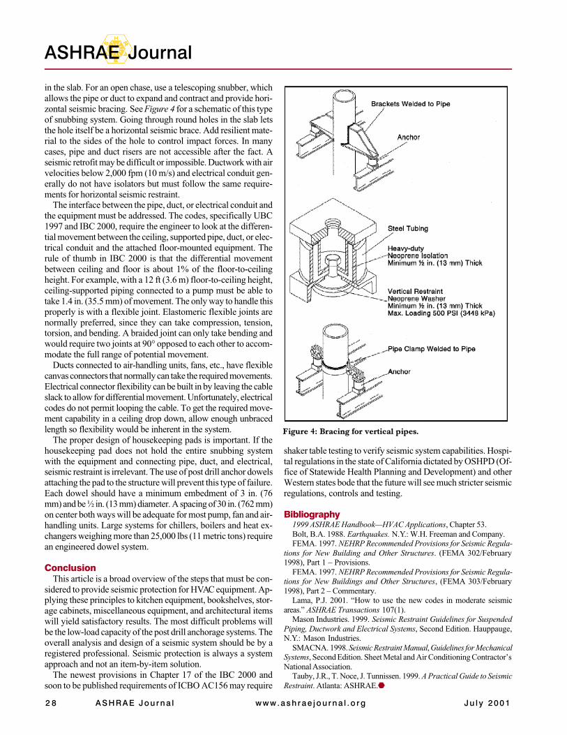
Figure 4: Bracing for vertical pipes.
in the slab. For an open chase, use a telescoping snubber, whichallows the pipe or duct to expand and contract and provide hori-zontal seismic bracing. See Figure 4 for a schematic of this typeof snubbing system. Going through round holes in the slab letsthe hole itself be a horizontal seismic brace. Add resilient mate-rial to the sides of the hole to control impact forces. In manycases, pipe and duct risers are not accessible after the fact. Aseismic retrofit may be difficult or impossible. Ductwork with airvelocities below 2,000 fpm (10 m/s) and electrical conduit gen-erally do not have isolators but must follow the same require-ments for horizontal seismic restraint.
The interface between the pipe, duct, or electrical conduit andthe equipment must be addressed. The codes, specifically UBC1997 and IBC 2000, require the engineer to look at the differen-tial movement between the ceiling, supported pipe, duct, or elec-trical conduit and the attached floor-mounted equipment. Therule of thumb in IBC 2000 is that the differential movementbetween ceiling and floor is about 1% of the floor-to-ceilingheight. For example, with a 12 ft (3.6 m) floor-to-ceiling height,ceiling-supported piping connected to a pump must be able totake 1.4 in. (35.5 mm) of movement. The only way to handle thisproperly is with a flexible joint. Elastomeric flexible joints arenormally preferred, since they can take compression, tension,torsion, and bending. A braided joint can only take bending andwould require two joints at 90° opposed to each other to accom-modate the full range of potential movement.
Ducts connected to air-handling units, fans, etc., have flexiblecanvas connectors that normally can take the required movements.Electrical connector flexibility can be built in by leaving the cableslack to allow for differential movement. Unfortunately, electricalcodes do not permit looping the cable. To get the required move-ment capability in a ceiling drop down, allow enough unbracedlength so flexibility would be inherent in the system.
The proper design of housekeeping pads is important. If thehousekeeping pad does not hold the entire snubbing systemwith the equipment and connecting pipe, duct, and electrical,seismic restraint is irrelevant. The use of post drill anchor dowelsattaching the pad to the structure will prevent this type of failure.Each dowel should have a minimum embedment of 3 in. (76mm) and be ½ in. (13 mm) diameter. A spacing of 30 in. (762 mm)on center both ways will be adequate for most pump, fan and air-handling units. Large systems for chillers, boilers and heat ex-changers weighing more than 25,000 lbs (11 metric tons) requirean engineered dowel system.
ConclusionThis article is a broad overview of the steps that must be con-
sidered to provide seismic protection for HVAC equipment. Ap-plying these principles to kitchen equipment, bookshelves, stor-age cabinets, miscellaneous equipment, and architectural itemswill yield satisfactory results. The most difficult problems willbe the low-load capacity of the post drill anchorage systems. Theoverall analysis and design of a seismic system should be by aregistered professional. Seismic protection is always a systemapproach and not an item-by-item solution.
The newest provisions in Chapter 17 of the IBC 2000 andsoon to be published requirements of ICBO AC156 may require
shaker table testing to verify seismic system capabilities. Hospi-tal regulations in the state of California dictated by OSHPD (Of-fice of Statewide Health Planning and Development) and otherWestern states bode that the future will see much stricter seismicregulations, controls and testing.
Bibliography1999 ASHRAE Handbook—HVAC Applications, Chapter 53.Bolt, B.A. 1988. Earthquakes. N.Y.: W.H. Freeman and Company.FEMA. 1997. NEHRP Recommended Provisions for Seismic Regula-
tions for New Building and Other Structures. (FEMA 302/February1998), Part 1 – Provisions.
FEMA. 1997. NEHRP Recommended Provisions for Seismic Regula-tions for New Buildings and Other Structures, (FEMA 303/February1998), Part 2 – Commentary.
Lama, P.J. 2001. “How to use the new codes in moderate seismicareas.” ASHRAE Transactions 107(1).
Mason Industries. 1999. Seismic Restraint Guidelines for SuspendedPiping, Ductwork and Electrical Systems, Second Edition. Hauppauge,N.Y.: Mason Industries.
SMACNA. 1998. Seismic Restraint Manual, Guidelines for MechanicalSystems, Second Edition. Sheet Metal and Air Conditioning Contractor’sNational Association.
Tauby, J.R., T. Noce, J. Tunnissen. 1999. A Practical Guide to SeismicRestraint. Atlanta: ASHRAE.
J u l y 2 0 0 1 ASHRAE Journa l 2 9
Seismic
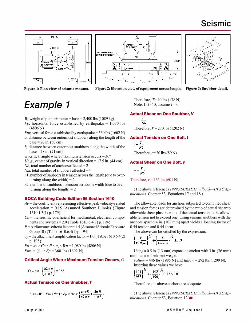
Figure 1: Plan view of seismic mounts. Figure 2: Elevation view of equipment across length. Figure 3: Snubber detail.
Therefore, T= 40 lbs (178 N)Note: If T < 0, assume T = 0
Actual Shear on One Snubber, V
Therefore, V = 270 lbs (1202 N)
Actual Tension on One Bolt, t
Therefore, t = 20 lbs (89 N)
Actual Shear on One Bolt, v
Therefore, v = 135 lbs (601 N)
(The above references 1999 ASHRAE Handbook—HVAC Ap-plications, Chapter 53, Equations 17 and 18.)
The allowable loads for anchors subjected to combined shearand tension forces are determined by the ratio of actual shear toallowable shear plus the ratio of the actual tension to the allow-able tension not to exceed one. Using seismic snubbers with theanchors spaced 4 in. (102 mm) apart yields a loading factor of0.54 tension and 0.44 shear.
The above can be satisfied by the expression:
Using a 0.5 in. (13 mm) expansion anchor with 3 in. (76 mm)minimum embedment we get:
Vallow = 446 lbs (1985 N) and Tallow = 292 lbs (1299 N).Inserting these values we have:
Therefore, the above anchors are adequate.
(The above references 1999 ASHRAE Handbook—HVAC Ap-plications, Chapter 53, Equation 12.)
Example 1
N)1602(lbs360 Fp Fpv =×=
W, weight of pump + motor + base = 2,400 lbs (1089 kg)Fp, horizontal force established by earthquake = 1,080 lbs
(4806 N)Fpv, vertical force established by earthquake = 360 lbs (1602 N)a, distance between outermost snubbers along the length of the
base = 20 in. (50 cm)b, distance between outermost snubbers along the width of the
base = 28 in. (71 cm)Θ, critical angle where maximum tension occurs = 36°Hc.g., center of gravity in vertical direction = 17.5 in. (44 cm)Nb, total number of anchors affected = 2Nm, total number of snubbers affected = 4n1, number of snubbers in tension across the length (due to over-
turning along the width) = 2n2, number of snubbers in tension across the width (due to over-
turning along the length) = 2
BOCA Building Code Edition 96 Section 1610Av = the coefficient representing effective peak velocity-related
acceleration = 0.15 (Assumed Southern Illinois) {Figure1610.1.3(1) p. 179}
Cc = the seismic coefficient for mechanical, electrical compo-nents and systems = 2.0 {Table 1610.6.4(1) p. 194}
P = performance criteria factor = 1.5 (Assumed Seismic ExposureGroup III) {Table 1610.6.4(1) p. 194}
ac = the attachment amplification factor = 1.0 {Table 1610.6.4(2)p. 195}
Fp = Av × Cc × P × ac × Wp = 1,080 lbs (4806 N)
Critical Angle Where Maximum Tension Occurs, Θ
Actual Tension on One Snubber, T
31
3 0 ASHRAE Journa l www.ash rae jou rna l .o rg J u l y 2 0 0 1
ASHRAE Journal
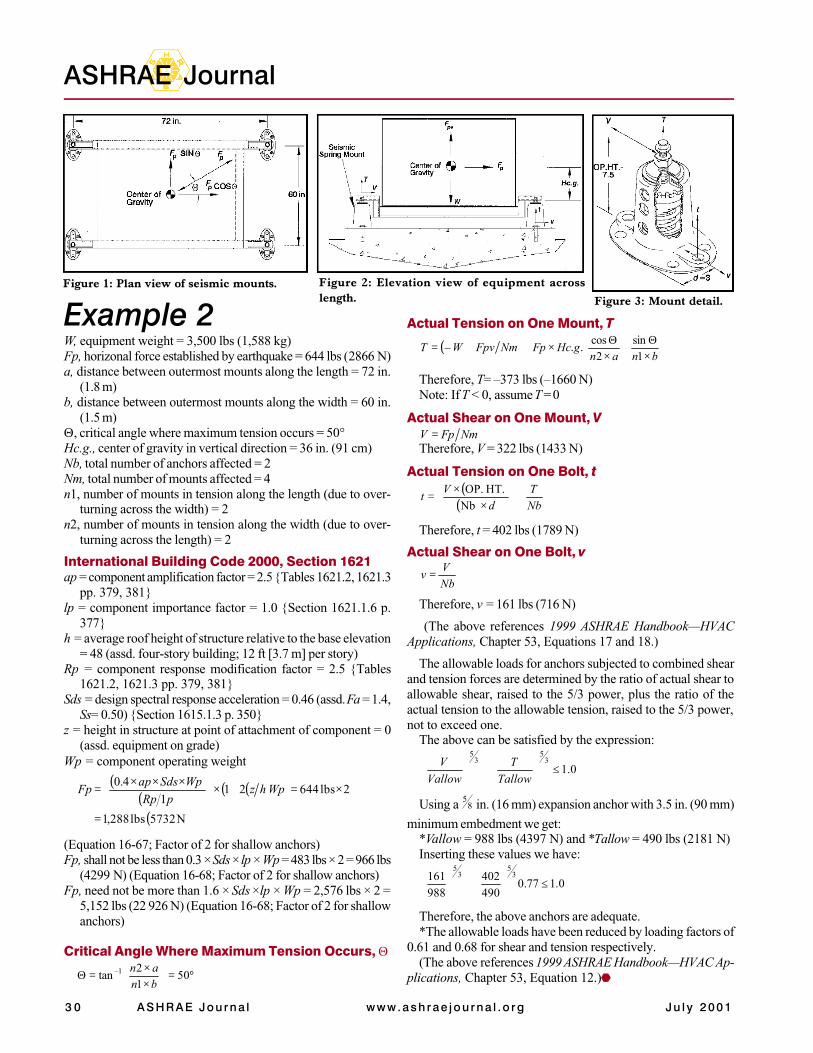
Example 2Figure 1: Plan view of seismic mounts. Figure 2: Elevation view of equipment across
length. Figure 3: Mount detail.
W, equipment weight = 3,500 lbs (1,588 kg)Fp, horizonal force established by earthquake = 644 lbs (2866 N)a, distance between outermost mounts along the length = 72 in.
(1.8 m)b, distance between outermost mounts along the width = 60 in.
(1.5 m)Θ, critical angle where maximum tension occurs = 50°Hc.g., center of gravity in vertical direction = 36 in. (91 cm)Nb, total number of anchors affected = 2Nm, total number of mounts affected = 4n1, number of mounts in tension along the length (due to over-
turning across the width) = 2n2, number of mounts in tension along the width (due to over-
turning across the length) = 2
International Building Code 2000, Section 1621ap = component amplification factor = 2.5 {Tables 1621.2, 1621.3
pp. 379, 381}lp = component importance factor = 1.0 {Section 1621.1.6 p.
377}h = average roof height of structure relative to the base elevation
= 48 (assd. four-story building; 12 ft [3.7 m] per story)Rp = component response modification factor = 2.5 {Tables
1621.2, 1621.3 pp. 379, 381}Sds = design spectral response acceleration = 0.46 (assd. Fa = 1.4,
Ss= 0.50) {Section 1615.1.3 p. 350}z = height in structure at point of attachment of component = 0
(assd. equipment on grade)Wp = component operating weight
( )( )
( )( )
( )N 5732 lbs 288,1
2lbs 644211
4.0
=
×=+×
×××
= WphzpRp
WpSdsapFp
(Equation 16-67; Factor of 2 for shallow anchors)Fp, shall not be less than 0.3 × Sds × lp × Wp = 483 lbs × 2 = 966 lbs
(4299 N) (Equation 16-68; Factor of 2 for shallow anchors)Fp, need not be more than 1.6 × Sds ×lp × Wp = 2,576 lbs × 2 =
5,152 lbs (22 926 N) (Equation 16-68; Factor of 2 for shallowanchors)
Critical Angle Where Maximum Tension Occurs, Θ
°=
××
=Θ 5012
tan 1–
bnan
Actual Tension on One Mount, T
( )
×Θ
+×Θ
×++=bnan
gHcFpNmFpvWT1
sin2
cos..–
Therefore, T= –373 lbs (–1660 N)Note: If T < 0, assume T = 0
Actual Shear on One Mount, VNmFpV =
Therefore, V = 322 lbs (1433 N)
Actual Tension on One Bolt, t( )
( ) NbT
dV
t +
××
=Nb
HT. OP.
Therefore, t = 402 lbs (1789 N)
Actual Shear on One Bolt, v
NbV
v =
Therefore, v = 161 lbs (716 N)
(The above references 1999 ASHRAE Handbook—HVACApplications, Chapter 53, Equations 17 and 18.)
The allowable loads for anchors subjected to combined shearand tension forces are determined by the ratio of actual shear toallowable shear, raised to the 5/3 power, plus the ratio of theactual tension to the allowable tension, raised to the 5/3 power,not to exceed one.
The above can be satisfied by the expression:
0.13
53
5
≤
+
TallowT
VallowV
Using a 85 in. (16 mm) expansion anchor with 3.5 in. (90 mm)
minimum embedment we get:*Vallow = 988 lbs (4397 N) and *Tallow = 490 lbs (2181 N)Inserting these values we have:
0.177.0490402
988161 3
53
5
≤
+
Therefore, the above anchors are adequate.*The allowable loads have been reduced by loading factors of
0.61 and 0.68 for shear and tension respectively.(The above references 1999 ASHRAE Handbook—HVAC Ap-
plications, Chapter 53, Equation 12.)