seismic damage analysis of box metro tunnels accounting
TRANSCRIPT

applied sciences
Article
Seismic Damage Analysis of Box Metro TunnelsAccounting for Aspect Ratio and Shear Failure
Duy-Duan Nguyen 1,2 , Tae-Hyung Lee 1 , Van-Quang Nguyen 2,3 and Duhee Park 3,*1 Department of Civil and Environmental Engineering, Konkuk University, Seoul 05029, Korea2 Department of Civil Engineering, Vinh University, Vinh 461010, Vietnam3 Department of Civil and Environmental Engineering, Hanyang University, Seoul 04763, Korea* Correspondence: [email protected]
Received: 6 July 2019; Accepted: 2 August 2019; Published: 7 August 2019�����������������
Abstract: We performed a series of inelastic frame analyses for single, double, and triple reinforcedconcrete box tunnels to investigate their unique damage mechanisms. We focused our interest on theinfluence of the aspect ratio of box tunnels and the occurrence of a shear structural failure. This is afollow-up study of Lee et al. (2016), where damage analyses of box tunnels with an aspect ratio ofunity were performed by considering only the flexural failure. We show that only flexural failuresoccurred in single box tunnels, whereas shear structural failures were produced at the inner columnfor double and triple box tunnels. The inner column failed in shear after flexural plastic hinges wereformed at all four outer corners, and might cause a brittle collapse. A structural collapse was notobserved in single box tunnels. An increase in the aspect ratio was demonstrated to cause associatedincrement in the seismic resistance. The moment and shear strains at which plastic hinges formed anincrease by up to 5% and 20%, respectively. We proposed revised damage indices (DIs) correspondingto three damage states for single box tunnels, where DI is defined as the ratio of the elastic moment tothe yield moment. The collapse damage state and corresponding DI for double and triple tunnels arenewly presented.
Keywords: box tunnel; seismic damage; shear failure; aspect ratio; inelastic frame analysis
1. Introduction
Recent large earthquakes have revealed that underground structures can experience a severedamage when subjected to a strong ground motion [1,2]. A number of studies investigated the damagepattern of tunnel structures in past earthquake events [1,3–11]. Such observations highlight the need tobetter understand the seismic performance and structural damage pattern of underground structures.
Seismic damage analyses of box tunnels can be performed by using experimental or/and numericalmethods. Zou et al. [12] conducted a series of numerical simulations and a verified shaking table test toinvestigate the seismic response and damage of a multi-story subway station. Then, they defined fourdamage states based on the damage parameter, which depends on the ductility of structural members.Chen et al. [13] studied the effect of pulse-like ground motions on seismic responses of a multi-storysubway station using shaking table test. Based on experimental results, they pointed out that the centercolumns were sensitive structural members, which can be suffered a significant vulnerability underearthquake excitations. Chen et al. [14] investigated the effects of axial compression ratio of interiorcolumns on failure modes and damage patterns of a multi-story underground structure using a seriesof numerical pushover analyses. Recently, some studies employed numerical approach to analyze theseismic failure and collapse mechanism of Daikai subway station [15–20]. They both gave a mutualconclusion that the structure was completely collapsed due to an extreme failure and loosing loadcapacity of the center column. Furthermore, an extensive summary of previous studies on the seismic
Appl. Sci. 2019, 9, 3207; doi:10.3390/app9163207 www.mdpi.com/journal/applsci

Appl. Sci. 2019, 9, 3207 2 of 14
analysis of tunnels are presented by Hashash et al. [1] and Lee et al. [21]. The previous studies dealtwith a specific tunnel and soil stiffness. A wide range of tunnel shapes and soil conditions is thereforeneeded to consider in seismic damage analyses. A set of damage states and corresponding damageindices of the box tunnels should also be defined and updated accordingly.
The dynamic analysis is recognized to provide the most realistic estimate of the seismic responseof tunnels. However, it was reported that the difference between the dynamic and pseudo-staticanalyses is insignificant [22,23]. Therefore, the numerical pseudo-static method is widely used inpractice and also in research [1,12,22–37].
Lee et al. [21] performed a pushover analyses for three representative cut-and-cover metro tunnelsin South Korea with an aspect ratio of unity, where the aspect ratio is defined as the width to heightratio (B/H) of a single unit. Damage state was defined as the number of plastic hinge formation anddamage index (DI) was defined as the ratio of the elastic moment (M) to the yield moment (My).The damage states and corresponding DIs of single, double, and triple box tunnels were presented.Three damage states were defined, which are minor, moderate, and extensive. The collapse state wasnot defined because only flexural failure mode was simulated and a structural failure was not observed.It was reported that the effect of the geometry and dimension of the box tunnels, and the possibility ofa shear failure should be investigated in a follow-up study.
We expand the study of Lee et al. [21] to investigate the effect of aspect ratio. A more advancednumerical model that can simulate the shear failure in the structural member that is used. We extensivelycollect design sections of metro tunnels built in Korea to investigate the variation of the aspect ratios andto develop representative sections. We perform a series of inelastic push-over analyses to identify thefailure mechanisms of representative single, double, and triple box tunnels subjected to seismic loading.Finally, recommendations for an update of the damage states and DIs of box tunnels are presented.
2. Description of Tunnels and Site Conditions
We used three types of rectangular cut-and-cover reinforced concrete box tunnels with variousaspect ratios, as shown in Figure 1. They were single, double, and triple box tunnels designed andconstructed for subway systems in South Korea. The baseline tunnel sections were developed based on91 structural sections of subway tunnels in Korea. The height (H) was 6.0 m for all box tunnels, whereasthe center-to-center width (B) varied from 6.0 m to 12.0 m. The aspect ratio (B/H) ranged from 1.0 to 2.0for single and double box tunnels. For triple box tunnels, B/H = 2.0 was not modeled because such asection was not shown to be used. Instead, two baseline configurations were modeled where B/H ofthe left unit and the center unit was 1.5, termed B/H = 1.5 L and B/H = 1.5 C, respectively. The thicknessof sidewalls, top slab and bottom slab was set to 1.0 m. The cross-sectional dimensions of the innercolumn of double and triple tunnels were 0.4 × 1.0 m, with a spacing of 1.0 m. The reinforcementratio of structural members, determined based on the actual structural design, increased compatiblywith an increment of the aspect ratios. The soil profile was assumed to be uniform and the depth ofoverburden was set to 7.0 m. The at-rest earth pressure coefficient (K0) was set to 0.5.

Appl. Sci. 2019, 9, 3207 3 of 14Appl. Sci. 2019, 9, x FOR PEER REVIEW 3 of 14
Figure 1. Sections of cut-and-cover box tunnels modeled: (a) Single, (b) double, and (c) triple boxes.
3. Numerical Modeling
The pseudo-static procedure presented in Lee et al. [21] was adopted to perform nonlinear analyses of the tunnel structures using two-dimensional (2D) frame elements. The tunnel structures were modeled using SAP2000 (ver. 15), a finite element analysis program [38]. We also modeled the joint-offset of the wall-slab and column-slab connections to simulate their relatively rigid behaviors. Details on the nonlinear concrete and steel models for the tunnels are presented in the study by Lee et al. [21]. Plastic flexural and hinge models were used for all frame elements. The performance of the plastic hinge was dictated by the moment-curvature and shear force–shear deformation relationships that were determined from a nonlinear section analysis. For the shear strength–shear deformation relation of a section, we adopted the definitions and guidelines of ACI-318 [39], FEMA-356 [40] and Park and Paulay [41] to determine the yield strength (Vy), ultimate strength (Vu), and the corresponding yield deformation (Δy) and ultimate deformation (Δu). The idealized shear model is illustrated in Figure 2. A series of normal and shear springs were attached to the nodes of the nonlinear frame elements to simulate soil-structure interaction, as defined according to the Seismic design code for metropolitan subway of Korea [42]. The horizontal and vertical normal spring constants, KH and KV, were defined as:
KH = kh0
h30
−3/4
, (1)
KV = kh0
b30
−3/4
, (2)
where 𝑘 = ( )𝐸 , h and b are the height and width of the tunnel, and ED is the elastic modulus of surrounding soil. The shear springs for vertical and horizontal, KSS and KSB, frames were defined as:
KSS = 1
4KH
, (3)
KSB = 1
4KV
. (4)
B
B
B
B/H = 2.0
B
(a)
B B
B
B
B/H = 1.5
B
H
B/H = 1.0 B/H = 2.0
B/H = 1.5 (C)
B/H = 1.0
B/H = 1.5 (L)(c)
B
B/H = 1.5
B/H = 1.0
(b)H
B
H
B
H
Figure 1. Sections of cut-and-cover box tunnels modeled: (a) Single, (b) double, and (c) triple boxes.
3. Numerical Modeling
The pseudo-static procedure presented in Lee et al. [21] was adopted to perform nonlinearanalyses of the tunnel structures using two-dimensional (2D) frame elements. The tunnel structureswere modeled using SAP2000 (ver. 15), a finite element analysis program [38]. We also modeled thejoint-offset of the wall-slab and column-slab connections to simulate their relatively rigid behaviors.Details on the nonlinear concrete and steel models for the tunnels are presented in the study by Lee etal. [21]. Plastic flexural and hinge models were used for all frame elements. The performance of theplastic hinge was dictated by the moment-curvature and shear force–shear deformation relationshipsthat were determined from a nonlinear section analysis. For the shear strength–shear deformationrelation of a section, we adopted the definitions and guidelines of ACI-318 [39], FEMA-356 [40] andPark and Paulay [41] to determine the yield strength (Vy), ultimate strength (Vu), and the correspondingyield deformation (∆y) and ultimate deformation (∆u). The idealized shear model is illustrated inFigure 2. A series of normal and shear springs were attached to the nodes of the nonlinear frameelements to simulate soil-structure interaction, as defined according to the Seismic design code formetropolitan subway of Korea [42]. The horizontal and vertical normal spring constants, KH and KV,were defined as:
KH = kh0
(h
30
)−3/4
, (1)
KV = kh0
(b
30
)−3/4
, (2)
where kh0 =(
130
)ED, h and b are the height and width of the tunnel, and ED is the elastic modulus of
surrounding soil. The shear springs for vertical and horizontal, KSS and KSB, frames were defined as:
KSS =14
KH, (3)
KSB =14
KV. (4)

Appl. Sci. 2019, 9, 3207 4 of 14Appl. Sci. 2019, 9, x FOR PEER REVIEW 4 of 14
Figure 2. Shear force–deformation relationship of the cross section.
Figure 3 shows the boundary conditions and imposed loads on a tunnel. Five uniform site profiles with shear wave velocities (Vs) of 50, 100, 200, 300 and 400 m/s were used. The Poisson’s ratio (ν) and unit weight were set to 0.3 and 20 kN/m3 for all profiles.
Figure 3. Boundary conditions and applied loads to the box tunnel.
Since the frame-spring model is an approximation of the continuum domain, there is a need to verify whether the simplified model realistically simulates the tunnel-soil interaction. The calculated values of the racking ratio (R) of box tunnels were compared with the finite difference analysis computations [43], a closed form solution [44], and finite element simulations [26] in Figure 4. R is defined as follows: 𝑅 = , (5)
where ΔBox is the relative displacement of top and bottom of the tunnel frame, and ΔFree-field is the relative displacement of soil profile at the top and bottom level of the tunnel. The calculated R is plotted against the flexibility ratio (F) of a rectangular tunnel, which is defined as [26]: 𝐹 = , (6)
where B and H are the width and height of the tunnel, Gm is the shear modulus of the surrounding soil, KS is the racking stiffness of tunnel, and KS = P/Δ, in which Δ is the lateral displacement due to the applied lateral force P at the roof of the tunnel.
Shear deformation (Δ)Δy
Vy
Vu
Shea
r stre
ngth
(V)
0.2Vy
Vu =1.1Vy
Δu=1.5Δy Δm=2.5Δy
Ground surface
Soil weight
Shear force
Geostatic Shear force
KH
KV KSBKSS
Bedrock
Soil deformation pressure
Figure 2. Shear force–deformation relationship of the cross section.
Figure 3 shows the boundary conditions and imposed loads on a tunnel. Five uniform site profileswith shear wave velocities (Vs) of 50, 100, 200, 300 and 400 m/s were used. The Poisson’s ratio (ν) andunit weight were set to 0.3 and 20 kN/m3 for all profiles.
Appl. Sci. 2019, 9, x FOR PEER REVIEW 4 of 14
Figure 2. Shear force–deformation relationship of the cross section.
Figure 3 shows the boundary conditions and imposed loads on a tunnel. Five uniform site profiles with shear wave velocities (Vs) of 50, 100, 200, 300 and 400 m/s were used. The Poisson’s ratio (ν) and unit weight were set to 0.3 and 20 kN/m3 for all profiles.
Figure 3. Boundary conditions and applied loads to the box tunnel.
Since the frame-spring model is an approximation of the continuum domain, there is a need to verify whether the simplified model realistically simulates the tunnel-soil interaction. The calculated values of the racking ratio (R) of box tunnels were compared with the finite difference analysis computations [43], a closed form solution [44], and finite element simulations [26] in Figure 4. R is defined as follows: 𝑅 = , (5)
where ΔBox is the relative displacement of top and bottom of the tunnel frame, and ΔFree-field is the relative displacement of soil profile at the top and bottom level of the tunnel. The calculated R is plotted against the flexibility ratio (F) of a rectangular tunnel, which is defined as [26]: 𝐹 = , (6)
where B and H are the width and height of the tunnel, Gm is the shear modulus of the surrounding soil, KS is the racking stiffness of tunnel, and KS = P/Δ, in which Δ is the lateral displacement due to the applied lateral force P at the roof of the tunnel.
Shear deformation (Δ)Δy
Vy
Vu
Shea
r stre
ngth
(V)
0.2Vy
Vu =1.1Vy
Δu=1.5Δy Δm=2.5Δy
Ground surface
Soil weight
Shear force
Geostatic Shear force
KH
KV KSBKSS
Bedrock
Soil deformation pressure
Figure 3. Boundary conditions and applied loads to the box tunnel.
Since the frame-spring model is an approximation of the continuum domain, there is a need toverify whether the simplified model realistically simulates the tunnel-soil interaction. The calculatedvalues of the racking ratio (R) of box tunnels were compared with the finite difference analysiscomputations [43], a closed form solution [44], and finite element simulations [26] in Figure 4. R isdefined as follows:
R =∆Box
∆Free− f ield, (5)
where ∆Box is the relative displacement of top and bottom of the tunnel frame, and ∆Free-field is therelative displacement of soil profile at the top and bottom level of the tunnel. The calculated R isplotted against the flexibility ratio (F) of a rectangular tunnel, which is defined as [26]:
F =(Gm
Ks
)( BH
), (6)
where B and H are the width and height of the tunnel, Gm is the shear modulus of the surrounding soil,KS is the racking stiffness of tunnel, and KS = P/∆, in which ∆ is the lateral displacement due to theapplied lateral force P at the roof of the tunnel.

Appl. Sci. 2019, 9, 3207 5 of 14
Appl. Sci. 2019, 9, x FOR PEER REVIEW 5 of 14
Figure 4. Comparison of racking ratio and flexibility ratio relationships.
The curve of Anderson [43], defined as 𝑅 = 2𝐹(1 𝐹), is based on pseudo-static analyses using four types of single box tunnels and five different burial depths. The Penzien [44] curve, 𝑅 =4(1 𝜈)𝐹 / 3 4𝜈 𝐹 , is derived from an analytical procedure. The curve of Wang [26] is derived from 25 dynamic finite element simulations using various rectangular tunnel sections, soil profiles, and input ground motions. The results of the frame analyses were consistent with the published curves, thus demonstrating that the frame analysis results were reliable.
4. Results and Discussion
4.1. Failure Mechanism of Tunnels with B/H = 1.0
In this section, we investigated the failure mechanisms of box tunnels due to flexure and shear yielding. For single box tunnels, a shear plastic hinge was shown not to develop, even after flexural plastic hinges were formed at all four corners. It was primarily due to the support from the surrounding soil medium. For double and triple box tunnels, both flexural and shear plastic hinges were observed. Figure 5 depicts the plastic hinge formation sequences of double box tunnels with Vs = 50 m/s and Vs = 400 m/s for soil. The dots in pink indicate locations of flexural plastic hinges and orange dots represent shear failure (loss of the shear capacity). It can be observed that shear plastic hinges started occurring in the double box tunnels at approximately 3% free-field shear strain with respect to Vs = 50 m/s (i.e., soft soil) and at about 0.7% shear strain with Vs = 400 m/s (i.e., stiff soil). It should be noted that the shear plastic hinges only form in the interior column after flexural plastic hinges form at all four corners of the outer frame. Moreover, the shear plastic hinges form throughout the interior column element almost simultaneously. Since the concrete member loses its axial load bearing capacity when it is severely damaged in shear, a structural collapse of the box tunnel was shown to occur. This collapse mechanism of reinforced concrete box structure is in line with those observed in previous studies [45–48].
Figure 4. Comparison of racking ratio and flexibility ratio relationships.
The curve of Anderson [43], defined as R = 2F(1 + F), is based on pseudo-static analysesusing four types of single box tunnels and five different burial depths. The Penzien [44] curve,R = [4(1− v)F]/[3− 4v + F], is derived from an analytical procedure. The curve of Wang [26]is derived from 25 dynamic finite element simulations using various rectangular tunnel sections,soil profiles, and input ground motions. The results of the frame analyses were consistent with thepublished curves, thus demonstrating that the frame analysis results were reliable.
4. Results and Discussion
4.1. Failure Mechanism of Tunnels with B/H = 1.0
In this section, we investigated the failure mechanisms of box tunnels due to flexure and shearyielding. For single box tunnels, a shear plastic hinge was shown not to develop, even after flexuralplastic hinges were formed at all four corners. It was primarily due to the support from the surroundingsoil medium. For double and triple box tunnels, both flexural and shear plastic hinges were observed.Figure 5 depicts the plastic hinge formation sequences of double box tunnels with Vs = 50 m/s andVs = 400 m/s for soil. The dots in pink indicate locations of flexural plastic hinges and orange dotsrepresent shear failure (loss of the shear capacity). It can be observed that shear plastic hingesstarted occurring in the double box tunnels at approximately 3% free-field shear strain with respect toVs = 50 m/s (i.e., soft soil) and at about 0.7% shear strain with Vs = 400 m/s (i.e., stiff soil). It shouldbe noted that the shear plastic hinges only form in the interior column after flexural plastic hingesform at all four corners of the outer frame. Moreover, the shear plastic hinges form throughout theinterior column element almost simultaneously. Since the concrete member loses its axial load bearingcapacity when it is severely damaged in shear, a structural collapse of the box tunnel was shown tooccur. This collapse mechanism of reinforced concrete box structure is in line with those observed inprevious studies [45–48].
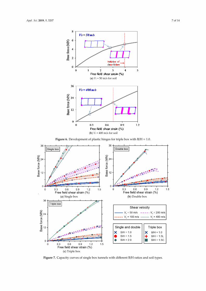
Figure 6 shows the formation and development of plastic hinges for triple box tunnels withVs = 50 m/s and Vs = 400 m/s for soil. Again, it was observed that the shear plastic hinges in theinterior columns form after flexural plastic hinges form at all four corners of the outer frame. The shearfailure occurred in the inner column of the triple box tunnel at about 4% free-field shear strain forVs = 50 m/s and 0.75% for Vs = 400 m/s. Even after the shear plastic hinges formed in the interiorcolumns, however, a complete collapse state was not observed for the triple box tunnel. This might bedue to the presence of two interior columns, which enhance the load bearing capacity and structuralredundancy. The internal forces were redistributed right after the occurrence of interior columnsyield in shear. As the lateral load increased, flexural plastic hinges at the corners continued to spread,while shear hinges at the interior columns maintained their shear strengths. It is disparate to whatis observed in the double box tunnel. It was also reported in [49] that an increase in the number of

Appl. Sci. 2019, 9, 3207 6 of 14
interior columns (number of bays) can produce additional structural redundancy of the reinforcedconcrete frame structures.Appl. Sci. 2019, 9, x FOR PEER REVIEW 6 of 14
(a) Vs = 50 m/s for soil
(b) Vs = 400 m/s for soil
Figure 5. Development of plastic hinges for double box with the width to height ratio (B/H) = 1.0
Figure 6 shows the formation and development of plastic hinges for triple box tunnels with Vs = 50 m/s and Vs = 400 m/s for soil. Again, it was observed that the shear plastic hinges in the interior columns form after flexural plastic hinges form at all four corners of the outer frame. The shear failure occurred in the inner column of the triple box tunnel at about 4% free-field shear strain for Vs = 50 m/s and 0.75% for Vs = 400 m/s. Even after the shear plastic hinges formed in the interior columns, however, a complete collapse state was not observed for the triple box tunnel. This might be due to the presence of two interior columns, which enhance the load bearing capacity and structural redundancy. The internal forces were redistributed right after the occurrence of interior columns yield in shear. As the lateral load increased, flexural plastic hinges at the corners continued to spread, while shear hinges at the interior columns maintained their shear strengths. It is disparate to what is observed in the double box tunnel. It was also reported in [49] that an increase in the number of interior columns (number of bays) can produce additional structural redundancy of the reinforced concrete frame structures.
Figure 5. Development of plastic hinges for double box with the width to height ratio (B/H) = 1.0
4.2. Effect of B/H on Damage of Box Tunnels
The capacity curves of all box tunnels are displayed in Figure 7. The base force was shown toincrease with an increase in the soil stiffness. Stiffer soil induced a smaller free field shear strain andyielded a larger base force. Figure 7 also reveals that the capacity of the tunnel was proportional to B/H.It was due to a higher lateral capacity produced by the shear springs at the slabs of the tunnel frame.Additionally, the capacity of the structural members was larger because the longitudinal reinforcementratio of the tunnel lining compatibly increases with B/H.
4.3. Updated Damage States and DIs of Box Tunnels
In this section, the effects of shear failure of the interior column and aspect ratio B/H on thedamage index (DI) and free-field shear strain are presented. We used the definitions of Lee et al. [21]for both the damage states and DIs but additionally account for the effect of B/H and shear failure.It is noted that DI is expressed as the ratio of the bending moment demand to the yield moment atthe critical sections of tunnel frames (i.e., M/My). Damage states are defined based on the number ofplastic hinges occurred in the tunnel frame and the corresponding DI.
Appl. Sci. 2019, 9, 3207 7 of 14Appl. Sci. 2019, 9, x FOR PEER REVIEW 7 of 14
(a) Vs = 50 m/s for soil
(b) Vs = 400 m/s for soil
Figure 6. Development of plastic hinges for triple box with B/H = 1.0.
4.2. Effect of B/H on Damage of Box Tunnels
The capacity curves of all box tunnels are displayed in Figure 7. The base force was shown to increase with an increase in the soil stiffness. Stiffer soil induced a smaller free field shear strain and yielded a larger base force. Figure 7 also reveals that the capacity of the tunnel was proportional to B/H. It was due to a higher lateral capacity produced by the shear springs at the slabs of the tunnel frame. Additionally, the capacity of the structural members was larger because the longitudinal reinforcement ratio of the tunnel lining compatibly increases with B/H.
(a) Single box (b) Double box
Figure 6. Development of plastic hinges for triple box with B/H = 1.0.
Appl. Sci. 2019, 9, x FOR PEER REVIEW 7 of 14
(a) Vs = 50 m/s for soil
(b) Vs = 400 m/s for soil
Figure 6. Development of plastic hinges for triple box with B/H = 1.0.
4.2. Effect of B/H on Damage of Box Tunnels
The capacity curves of all box tunnels are displayed in Figure 7. The base force was shown to increase with an increase in the soil stiffness. Stiffer soil induced a smaller free field shear strain and yielded a larger base force. Figure 7 also reveals that the capacity of the tunnel was proportional to B/H. It was due to a higher lateral capacity produced by the shear springs at the slabs of the tunnel frame. Additionally, the capacity of the structural members was larger because the longitudinal reinforcement ratio of the tunnel lining compatibly increases with B/H.
(a) Single box (b) Double box
Appl. Sci. 2019, 9, x FOR PEER REVIEW 8 of 14
(c) Triple box
Figure 7. Capacity curves of single box tunnels with different B/H ratios and soil types.
4.3. Updated Damage States and DIs of Box Tunnels
In this section, the effects of shear failure of the interior column and aspect ratio B/H on the damage index (DI) and free-field shear strain are presented. We used the definitions of Lee et al. [21] for both the damage states and DIs but additionally account for the effect of B/H and shear failure. It is noted that DI is expressed as the ratio of the bending moment demand to the yield moment at the critical sections of tunnel frames (i.e., M/My). Damage states are defined based on the number of plastic hinges occurred in the tunnel frame and the corresponding DI.
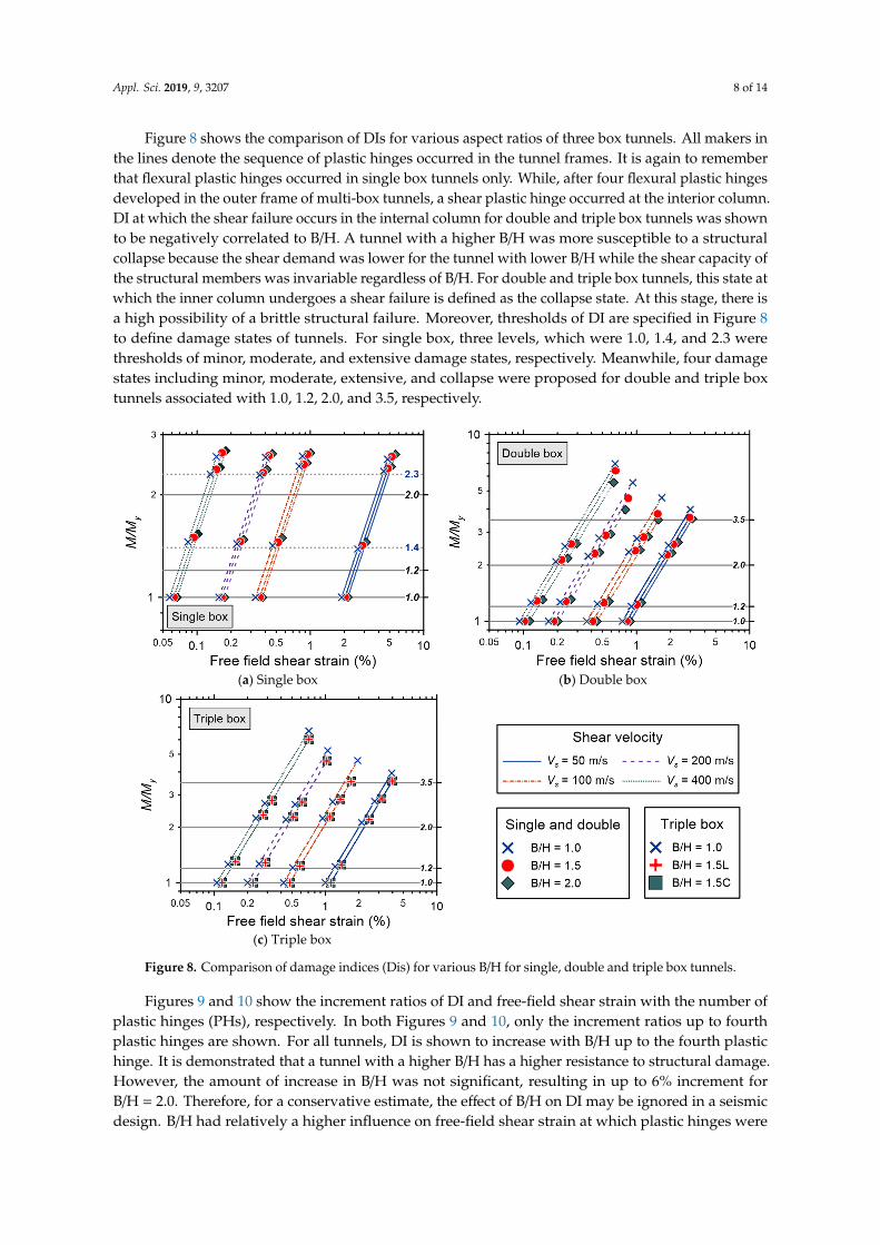
Figure 8 shows the comparison of DIs for various aspect ratios of three box tunnels. All makers in the lines denote the sequence of plastic hinges occurred in the tunnel frames. It is again to remember that flexural plastic hinges occurred in single box tunnels only. While, after four flexural plastic hinges developed in the outer frame of multi-box tunnels, a shear plastic hinge occurred at the interior column. DI at which the shear failure occurs in the internal column for double and triple box tunnels was shown to be negatively correlated to B/H. A tunnel with a higher B/H was more susceptible to a structural collapse because the shear demand was lower for the tunnel with lower B/H while the shear capacity of the structural members was invariable regardless of B/H. For double and triple box tunnels, this state at which the inner column undergoes a shear failure is defined as the collapse state. At this stage, there is a high possibility of a brittle structural failure. Moreover, thresholds of DI are specified in Figure 8 to define damage states of tunnels. For single box, three levels, which were 1.0, 1.4, and 2.3 were thresholds of minor, moderate, and extensive damage states, respectively. Meanwhile, four damage states including minor, moderate, extensive, and collapse were proposed for double and triple box tunnels associated with 1.0, 1.2, 2.0, and 3.5, respectively.
(a) Single box (b) Double box
Figure 7. Capacity curves of single box tunnels with different B/H ratios and soil types.
Appl. Sci. 2019, 9, 3207 8 of 14
Figure 8 shows the comparison of DIs for various aspect ratios of three box tunnels. All makers inthe lines denote the sequence of plastic hinges occurred in the tunnel frames. It is again to rememberthat flexural plastic hinges occurred in single box tunnels only. While, after four flexural plastic hingesdeveloped in the outer frame of multi-box tunnels, a shear plastic hinge occurred at the interior column.DI at which the shear failure occurs in the internal column for double and triple box tunnels was shownto be negatively correlated to B/H. A tunnel with a higher B/H was more susceptible to a structuralcollapse because the shear demand was lower for the tunnel with lower B/H while the shear capacity ofthe structural members was invariable regardless of B/H. For double and triple box tunnels, this state atwhich the inner column undergoes a shear failure is defined as the collapse state. At this stage, there isa high possibility of a brittle structural failure. Moreover, thresholds of DI are specified in Figure 8to define damage states of tunnels. For single box, three levels, which were 1.0, 1.4, and 2.3 werethresholds of minor, moderate, and extensive damage states, respectively. Meanwhile, four damagestates including minor, moderate, extensive, and collapse were proposed for double and triple boxtunnels associated with 1.0, 1.2, 2.0, and 3.5, respectively.
Appl. Sci. 2019, 9, x FOR PEER REVIEW 8 of 14
(c) Triple box
Figure 7. Capacity curves of single box tunnels with different B/H ratios and soil types.
4.3. Updated Damage States and DIs of Box Tunnels
In this section, the effects of shear failure of the interior column and aspect ratio B/H on the damage index (DI) and free-field shear strain are presented. We used the definitions of Lee et al. [21] for both the damage states and DIs but additionally account for the effect of B/H and shear failure. It is noted that DI is expressed as the ratio of the bending moment demand to the yield moment at the critical sections of tunnel frames (i.e., M/My). Damage states are defined based on the number of plastic hinges occurred in the tunnel frame and the corresponding DI.
Figure 8 shows the comparison of DIs for various aspect ratios of three box tunnels. All makers in the lines denote the sequence of plastic hinges occurred in the tunnel frames. It is again to remember that flexural plastic hinges occurred in single box tunnels only. While, after four flexural plastic hinges developed in the outer frame of multi-box tunnels, a shear plastic hinge occurred at the interior column. DI at which the shear failure occurs in the internal column for double and triple box tunnels was shown to be negatively correlated to B/H. A tunnel with a higher B/H was more susceptible to a structural collapse because the shear demand was lower for the tunnel with lower B/H while the shear capacity of the structural members was invariable regardless of B/H. For double and triple box tunnels, this state at which the inner column undergoes a shear failure is defined as the collapse state. At this stage, there is a high possibility of a brittle structural failure. Moreover, thresholds of DI are specified in Figure 8 to define damage states of tunnels. For single box, three levels, which were 1.0, 1.4, and 2.3 were thresholds of minor, moderate, and extensive damage states, respectively. Meanwhile, four damage states including minor, moderate, extensive, and collapse were proposed for double and triple box tunnels associated with 1.0, 1.2, 2.0, and 3.5, respectively.
(a) Single box (b) Double box
Appl. Sci. 2019, 9, x FOR PEER REVIEW 9 of 14
(c) Triple box
Figure 8. Comparison of damage indices (Dis) for various B/H for single, double and triple box tunnels.
Figures 9 and 10 show the increment ratios of DI and free-field shear strain with the number of plastic hinges (PHs), respectively. In both Figures 9 and 10, only the increment ratios up to fourth plastic hinges are shown. For all tunnels, DI is shown to increase with B/H up to the fourth plastic hinge. It is demonstrated that a tunnel with a higher B/H has a higher resistance to structural damage. However, the amount of increase in B/H was not significant, resulting in up to 6% increment for B/H = 2.0. Therefore, for a conservative estimate, the effect of B/H on DI may be ignored in a seismic design. B/H had relatively a higher influence on free-field shear strain at which plastic hinges were formed, as shown in Figure 10. The increment was up to 16% for single tunnels. However, it ranged from 23% to 27% for double and triple tunnels, respectively. This illustrates that a higher level of free field ground motion is needed to damage tunnels with a high B/H.
Table 1 shows the updated damage states, number of plastic hinges (NPH), and DIs corresponding to the respective damage states. For single box tunnels, the upper limits of DIs for minor and moderate damage states increased from 1.2 and 2.0 to 1.4 and 2.3, respectively. The cause for this increment was not because of the shear failure mode, which did not occur in single box tunnels, or the influence of B/H. It is because from Lee et al. [21], conservative DIs were assigned such that they are identical for single, double, and triple boxes. However, increased values were recommended in this study because DIs by Lee et al. [21] for single box tunnels are too conservative. For double and triple box tunnels, DIs did not change from minor up to the excessive damage states. We newly presented DI for the collapse damage state, which was conservatively proposed as 3.5 for all types of double and triple tunnels, even though DI was revealed to depend on the type and B/H of the tunnel, as well as Vs for soil. Such conservatism was necessary because a brittle structural failure may cause substantial damage, and therefore should be avoided.
(a) Single box with [B/H = 1.5]/[B/H = 1.0] (b) Single box with [B/H = 2.0]/[B/H = 1.0]
Figure 8. Comparison of damage indices (Dis) for various B/H for single, double and triple box tunnels.
Figures 9 and 10 show the increment ratios of DI and free-field shear strain with the number ofplastic hinges (PHs), respectively. In both Figures 9 and 10, only the increment ratios up to fourthplastic hinges are shown. For all tunnels, DI is shown to increase with B/H up to the fourth plastichinge. It is demonstrated that a tunnel with a higher B/H has a higher resistance to structural damage.However, the amount of increase in B/H was not significant, resulting in up to 6% increment forB/H = 2.0. Therefore, for a conservative estimate, the effect of B/H on DI may be ignored in a seismicdesign. B/H had relatively a higher influence on free-field shear strain at which plastic hinges were

Appl. Sci. 2019, 9, 3207 9 of 14
formed, as shown in Figure 10. The increment was up to 16% for single tunnels. However, it rangedfrom 23% to 27% for double and triple tunnels, respectively. This illustrates that a higher level of freefield ground motion is needed to damage tunnels with a high B/H.
Appl. Sci. 2019, 9, x FOR PEER REVIEW 9 of 14
(c) Triple box
Figure 8. Comparison of damage indices (Dis) for various B/H for single, double and triple box tunnels.
Figures 9 and 10 show the increment ratios of DI and free-field shear strain with the number of plastic hinges (PHs), respectively. In both Figures 9 and 10, only the increment ratios up to fourth plastic hinges are shown. For all tunnels, DI is shown to increase with B/H up to the fourth plastic hinge. It is demonstrated that a tunnel with a higher B/H has a higher resistance to structural damage. However, the amount of increase in B/H was not significant, resulting in up to 6% increment for B/H = 2.0. Therefore, for a conservative estimate, the effect of B/H on DI may be ignored in a seismic design. B/H had relatively a higher influence on free-field shear strain at which plastic hinges were formed, as shown in Figure 10. The increment was up to 16% for single tunnels. However, it ranged from 23% to 27% for double and triple tunnels, respectively. This illustrates that a higher level of free field ground motion is needed to damage tunnels with a high B/H.
Table 1 shows the updated damage states, number of plastic hinges (NPH), and DIs corresponding to the respective damage states. For single box tunnels, the upper limits of DIs for minor and moderate damage states increased from 1.2 and 2.0 to 1.4 and 2.3, respectively. The cause for this increment was not because of the shear failure mode, which did not occur in single box tunnels, or the influence of B/H. It is because from Lee et al. [21], conservative DIs were assigned such that they are identical for single, double, and triple boxes. However, increased values were recommended in this study because DIs by Lee et al. [21] for single box tunnels are too conservative. For double and triple box tunnels, DIs did not change from minor up to the excessive damage states. We newly presented DI for the collapse damage state, which was conservatively proposed as 3.5 for all types of double and triple tunnels, even though DI was revealed to depend on the type and B/H of the tunnel, as well as Vs for soil. Such conservatism was necessary because a brittle structural failure may cause substantial damage, and therefore should be avoided.
(a) Single box with [B/H = 1.5]/[B/H = 1.0] (b) Single box with [B/H = 2.0]/[B/H = 1.0]
Appl. Sci. 2019, 9, x FOR PEER REVIEW 10 of 14
(c) Double box with [B/H = 1.5]/[B/H = 1.0] (d) Double box with [B/H = 2.0]/[B/H = 1.0]
(e) Triple box with [B/H = 1.5L]/[B/H = 1.0] (f) Triple box with [B/H = 1.5C]/[B/H = 1.0]
Figure 9. Increment ratio of DI with B/H vs. number of plastic hinges (PHs) of box tunnels for various shear wave velocities (Vs) values.
(a) Single box with [B/H = 1.5]/[B/H = 1.0] (b) Single box with [B/H = 2.0]/[B/H = 1.0]
Figure 9. Increment ratio of DI with B/H vs. number of plastic hinges (PHs) of box tunnels for variousshear wave velocities (Vs) values.

Appl. Sci. 2019, 9, 3207 10 of 14
Appl. Sci. 2019, 9, x FOR PEER REVIEW 10 of 14
(c) Double box with [B/H = 1.5]/[B/H = 1.0] (d) Double box with [B/H = 2.0]/[B/H = 1.0]
(e) Triple box with [B/H = 1.5L]/[B/H = 1.0] (f) Triple box with [B/H = 1.5C]/[B/H = 1.0]
Figure 9. Increment ratio of DI with B/H vs. number of plastic hinges (PHs) of box tunnels for various shear wave velocities (Vs) values.
(a) Single box with [B/H = 1.5]/[B/H = 1.0] (b) Single box with [B/H = 2.0]/[B/H = 1.0]
Appl. Sci. 2019, 9, x FOR PEER REVIEW 11 of 14
(c) Double box with [B/H = 1.5]/[B/H = 1.0] (d) Double box with [B/H = 2.0]/[B/H = 1.0]
(e) Triple box with [B/H = 1.5L]/[B/H = 1.0] (f) Triple box with [B/H = 1.5C]/[B/H = 1.0] Figure 10. Increment ratio of free-field shear strain with B/H vs. the number of PHs of box tunnels for various Vs values.
Table 1. Updated definitions of damage states and corresponding DIs. Damage state definitions and DIs of Lee et al. [21] are listed for comparison purposes.
Tunnel Type Damage State Number of Plastic Hinges (NPH) DI of Lee et al. [21] Updated DI
Single box
None 0 DI < 1.0 DI < 1.0 Minor 1 ≤ NPH < 2 1.0 ≤ DI < 1.2 1.0 ≤ DI < 1.4
Moderate 2 ≤ NPH < 3 1.2 ≤ DI < 2.0 1.4 ≤ DI < 2.3 Extensive 3 ≤ NPH 2.0 ≤ DI 2.3 ≤ DI
Double box Triple box
None 0 DI < 1.0 DI < 1.0 Minor 1 ≤ NPH < 2 1.0 ≤ DI < 1.2 1.0 ≤ DI < 1.2
Moderate 2 ≤ NPH < 3 1.2 ≤ DI < 2.0 1.2 ≤ DI < 2.0 Extensive 3 ≤ NPH < 5 2.0 ≤ DI 2.0 ≤ DI < 3.5 Collapse 5 ≤ NPH N.A. 3.5 ≤ DI
The purpose of this study was focused on the investigation of damage mechanisms of one-story box tunnels in South Korea. The selected tunnel shapes are typical for cut-and-cover subway tunnels in the country. A wide range of surrounding soil conditions/stiffness was also considered in this research. A comparison of the present R–F relationships and the published curves, which were developed for worldwide box tunnels, is conducted, highlighting that the model used in this study was in line with the previous works (see Figure 4). Additionally, a comparison of updated damage indices and previous indices is presented in Table 1. Therefore, the findings of this study could be readily applied for similar box tunnel configurations located in different soil stiffness regardless using South Korean design standards.
5. Conclusions
Figure 10. Increment ratio of free-field shear strain with B/H vs. the number of PHs of box tunnels forvarious Vs values.
Table 1 shows the updated damage states, number of plastic hinges (NPH), and DIs correspondingto the respective damage states. For single box tunnels, the upper limits of DIs for minor and moderatedamage states increased from 1.2 and 2.0 to 1.4 and 2.3, respectively. The cause for this increment wasnot because of the shear failure mode, which did not occur in single box tunnels, or the influence ofB/H. It is because from Lee et al. [21], conservative DIs were assigned such that they are identical forsingle, double, and triple boxes. However, increased values were recommended in this study becauseDIs by Lee et al. [21] for single box tunnels are too conservative. For double and triple box tunnels,DIs did not change from minor up to the excessive damage states. We newly presented DI for thecollapse damage state, which was conservatively proposed as 3.5 for all types of double and triple

Appl. Sci. 2019, 9, 3207 11 of 14
tunnels, even though DI was revealed to depend on the type and B/H of the tunnel, as well as Vs
for soil. Such conservatism was necessary because a brittle structural failure may cause substantialdamage, and therefore should be avoided.
Table 1. Updated definitions of damage states and corresponding DIs. Damage state definitions andDIs of Lee et al. [21] are listed for comparison purposes.
Tunnel Type Damage State Number of Plastic Hinges (NPH) DI of Lee et al. [21] Updated DI
Single box
None 0 DI < 1.0 DI < 1.0Minor 1 ≤ NPH < 2 1.0 ≤ DI < 1.2 1.0 ≤ DI < 1.4
Moderate 2 ≤ NPH < 3 1.2 ≤ DI < 2.0 1.4 ≤ DI < 2.3Extensive 3 ≤ NPH 2.0 ≤ DI 2.3 ≤ DI
Double boxTriple box
None 0 DI < 1.0 DI < 1.0Minor 1 ≤ NPH < 2 1.0 ≤ DI < 1.2 1.0 ≤ DI < 1.2
Moderate 2 ≤ NPH < 3 1.2 ≤ DI < 2.0 1.2 ≤ DI < 2.0Extensive 3 ≤ NPH < 5 2.0 ≤ DI 2.0 ≤ DI < 3.5Collapse 5 ≤ NPH N.A. 3.5 ≤ DI
The purpose of this study was focused on the investigation of damage mechanisms of one-storybox tunnels in South Korea. The selected tunnel shapes are typical for cut-and-cover subway tunnels inthe country. A wide range of surrounding soil conditions/stiffness was also considered in this research.A comparison of the present R–F relationships and the published curves, which were developedfor worldwide box tunnels, is conducted, highlighting that the model used in this study was in linewith the previous works (see Figure 4). Additionally, a comparison of updated damage indices andprevious indices is presented in Table 1. Therefore, the findings of this study could be readily appliedfor similar box tunnel configurations located in different soil stiffness regardless using South Koreandesign standards.
5. Conclusions
The seismic failure mechanisms of single-story rectangular cut-and-cover tunnels with variousaspect ratios were identified and their damage states were updated using the nonlinear frame modeland a series of pushover analyses. The shear wave velocity of the soil was varied from 50 to 400 m/s.The numerical model was verified against published relationships between the racking ratio and theflexibility ratio. Based on the numerical analysis results, the following conclusions are drawn.
• A collapse damage state was not observed for the single box tunnels even after plastic hingesformed at all corners, primarily due to the support from the surrounding soil medium. The shearplastic hinge did not form in the single tunnel.
• For double and triple tunnels, the shear plastic hinges formed at the interior columns after flexureplastic hinges developed at all outer frame corners. The shear failure at the interior columnmay lead to a brittle structural collapse for multi-box tunnels. This failure should be avoided indesign practices.
• The aspect ratio did not significantly influence the damage index (DI) of the single box tunnels.For double and triple tunnels, DIs at which the inner column failed was dependent on the aspectratio. The shear strains corresponding to the damage states were more sensitive to the aspect ratiocompared with DI.
• Damage states of box tunnels and corresponding DIs were updated from the study of Lee etal. [21]. DIs range from 1.0 to 2.3 for three damage states of single box tunnels, which wereminor, moderate, and extensive states. The collapse damage state was newly proposed and thecorresponding DI was presented for double and triple box tunnels. DIs ranged from 1.0 to 3.5.

Appl. Sci. 2019, 9, 3207 12 of 14
Author Contributions: D.P. and T.-H.L. conceived the idea, outlined the work, and reviewed the manuscript;D.-D.N. performed the numerical analyses and wrote the manuscript; V.-Q.N. supported in performing numericalsimulations and summarizing the results.
Funding: This research was supported by the National Research Council of Science & Technology (NST) grantnumber CRC-16-02-KICT funded by the Korean government (MSIP).
Conflicts of Interest: The authors declare no conflict of interest.
References
1. Hashash, Y.M.; Hook, J.J.; Schmidt, B.; John, I.; Yao, C. Seismic design and analysis of underground structures.Tunn. Undergr. Space Tech. 2001, 16, 247–293. [CrossRef]
2. Roy, N.; Sarkar, R. A Review of Seismic Damage of Mountain Tunnels and Probable Failure Mechanisms.Geotech. Geol. Eng. 2017, 35, 1–28. [CrossRef]
3. Dowding, C.H.; Rozan, A. Damage to rock tunnels from earthquake shaking. J. Soil Mech. Found. Div. 1978,104, 175–191.
4. Owen, G.N.; Scholl, R.E. Earthquake Engineering of Large Underground Structures; The Division, NationalTechnical Information Service: Alexandria, VA, USA, 1981.
5. Sharma, S.; Judd, W.R. Underground opening damage from earthquakes. Eng. Geol. 1991, 30, 263–276.[CrossRef]
6. Wang, J. The distribution of earthquake damage to underground facilities during the 1976 Tang-Shanearthquake. Earthq. Spectra 1985, 1, 741–757.
7. Wang, Z.; Zhang, Z. Seismic damage classification and risk assessment of mountain tunnels with a validationfor the 2008 Wenchuan earthquake. Soil Dyn. Earthq. Eng. 2013, 45, 45–55. [CrossRef]
8. Nakamura, S.; Yoshida, N.; Iwatate, T. Damage to Daikai subway station during the 1995 Hyogoken-Nambuearthquake and its investigation. Jpn. Soc. Civ. Eng. Comm. Earthq. Eng. 1996, 287–295.
9. Shen, Y.; Gao, B.; Yang, X.; Tao, S. Seismic damage mechanism and dynamic deformation characteristicanalysis of mountain tunnel after Wenchuan earthquake. Eng. Geol. 2014, 180, 85–98. [CrossRef]
10. Wang, W.; Wang, T.; Su, J.; Lin, C.; Seng, C.; Huang, T. Assessment of damage in mountain tunnels due to theTaiwan Chi-Chi Earthquake. Tunn. Undergr. Space Tech. 2001, 16, 133–150. [CrossRef]
11. Yu, H.; Chen, J.; Bobet, A.; Yuan, Y. Damage observation and assessment of the Longxi tunnel during theWenchuan earthquake. Tunn. Undergr. Space Tech. 2016, 54, 102–116. [CrossRef]
12. Zou, Y.; Liu, H.; Jing, L.; Cui, J. A pseudo-static method for seismic responses of underground framestructures subjected to increasing excitations. Tunn. Undergr. Space Tech. 2017, 65, 106–120. [CrossRef]
13. Chen, Z.; Chen, W.; Li, Y.; Yuan, Y. Shaking table test of a multi-story subway station under pulse-like groundmotions. Soil Dyn. Earthq. Eng. 2016, 82, 111–122. [CrossRef]
14. Chen, Z.; Chen, W.; Zhang, W.; Lou, M. Effects of Axial Compression Ratio of Central Columns on SeismicPerformance of a Multi-Story Underground Structure. Int. J. Comput. Methods 2016, 13, 1641014. [CrossRef]
15. Li, W.; Chen, Q. Seismic performance and failure mechanism of a subway station based on nonlinear finiteelement analysis. KSCE J. Civ. Eng. 2018, 22, 765–776. [CrossRef]
16. Ma, C.; Lu, D.-C.; Du, X.-L.; Qi, C.-Z.; Zhang, X.-Y. Structural components functionalities and failuremechanism of rectangular underground structures during earthquakes. Soil Dyn. Earthq. Eng. 2019,119, 265–280. [CrossRef]
17. Lu, C.C.; Hwang, J.H. Nonlinear collapse simulation of Daikai Subway in the 1995 Kobe earthquake:Necessity of dynamic analysis for a shallow tunnel. Tunn. Undergr. Space Tech. 2019, 87, 78–90. [CrossRef]
18. Sayed, M.A.; Kwon, O.S.; Park, D.; Van Nguyen, Q. Multi-platform soil-structure interaction simulation ofDaikai subway tunnel during the 1995 Kobe earthquake. Soil Dyn. Earthq. Eng. 2019, 125, 105643. [CrossRef]
19. Liu, J.; Liu, X. Pushover analysis of Daikai subway station during the Osaka-Kobe earthquake in 1995. InProceedings of the 14th World Conference on Earthquake Engineering, Beijing, China, 12–17 October 2008;pp. 12–17.
20. Liu, T.; Chen, Z.; Yuan, Y.; Shao, X. Fragility analysis of a subway station structure by incremental dynamicanalysis. Adv. Struct. Eng. 2017, 20, 111–1124. [CrossRef]
21. Lee, T.H.; Park, D.; Nguyen, D.D.; Park, J.S. Damage analysis of cut-and-cover tunnel structures underseismic loading. Bull. Earthq. Eng. 2016, 14, 413–431. [CrossRef]

Appl. Sci. 2019, 9, 3207 13 of 14
22. Hashash, Y.; Karina, K.; Koutsoftas, D.; O’Riordan, N. Seismic design considerations for undergroundbox structures. In Proceedings of the Earth Retention Conference, Bellevue, WA, USA, 1–4 August 2010;pp. 620–637.
23. Argyroudis, S.; Pitilakis, K. Seismic fragility curves of shallow tunnels in alluvial deposits. Soil Dyn.Earthq. Eng. 2012, 35, 1–12. [CrossRef]
24. Debiasi, E.; Gajo, A.; Zonta, D. On the seismic response of shallow-buried rectangular structures. Tunn. Undergr.Space Tech. 2013, 38, 99–113. [CrossRef]
25. Park, D.; Sagong, M.; Kwak, D.Y.; Jeong, C.G. Simulation of tunnel response under spatially varying groundmotion. Soil Dyn. Earthq. Eng. 2009, 29, 1417–1424. [CrossRef]
26. Wang, J.N. Seismic Design of Tunnels: A Simple State-of-the-Art Design Approach; Parsons Brinckerhoff: New York,NY, USA, 1993.
27. Wood, J.H. Earthquake Design Procedures for Rectangular Underground Structures; Earthquake CommissionResearch Foundation: Wellington, New Zealand, 2004.
28. Yoo, J.K.; Park, J.S.; Park, D.; Lee, S.W. Seismic response of circular tunnels in jointed rock. KSCE J. Civ. Eng.2018, 22, 1121–1129. [CrossRef]
29. Tsinidis, G.; Rovithis, E.; Pitilakis, K.; Chazelas, J.L. Seismic response of box-type tunnels in soft soil:Experimental and numerical investigation. Tunn. Undergr. Space Tech. 2016, 59, 199–214. [CrossRef]
30. Katona, M.G. Seismic design and analysis of buried culverts and structures. J. Pipeline Syst. Eng. Pract. 2010,1, 111–119. [CrossRef]
31. Liu, R.; Shi, H. An improved pseudo-static method for seismic resistant design of underground structures.Earthq. Eng. Eng. Vib. 2006, 5, 189–193. [CrossRef]
32. Lu, C.C.; Hwang, J.H. Implementation of the modified cross-section racking deformation method usingexplicit FDM program: A critical assessment. Tunn. Undergr. Space Tech. 2017, 68, 58–73. [CrossRef]
33. Zhang, B.; Wang, X.; Zhang, J.; Meng, F. Three-dimensional limit analysis of seismic stability of tunnel faceswith quasi-static method. Geomech. Eng. 2017, 13, 301–318.
34. Do, N.A.; Dias, D.; Oreste, P.; Djeran-Maigre, I. 2D numerical investigations of twin tunnel interaction.Geomech. Eng. 2014, 6, 263–275. [CrossRef]
35. Nguyen, D.D.; Park, D.; Shamsher, S.; Nguyen, V.Q.; Lee, T.H. Seismic vulnerability assessment of rectangularcut-and-cover subway tunnels. Tunn. Undergr. Space Tech. 2019, 86, 247–261. [CrossRef]
36. Xu, Z.; Du, X.; Xu, C.; Jiang, J.; Han, R. Simplified equivalent static methods for seismic analysis of shallowburied rectangular underground structures. Soil Dyn. Earthq. Eng. 2019, 121, 1–11. [CrossRef]
37. Huh, J.; Tran, Q.H.; Haldar, A.; Park, I.; Ahn, J.H. Seismic Vulnerability Assessment of a Shallow Two-StoryUnderground RC Box Structure. Appl. Sci. 2017, 7, 735. [CrossRef]
38. CSI SAP2000 Software, ver15; Computer and Structures Inc.: Berkeley, CA, USA, 2011.39. ACI-318. Building Code Requirements for Structural Concrete and Commentary; American Concrete Institute:
Farmington Hills, MI, USA, 2008.40. FEMA-356. Prestandard and Commentary for the Seismic Rehabilitation of Buildings; Federal Emergency
Management Agency: Washington, DC, USA, 2000.41. Park, R.; Paulay, T. Reinforced Concrete Structures; John Wiley & Sons: Hoboken, NJ, USA, 1975.42. MLTM. Earthquake Resistance Design Regulations for Subway Structures; Ministry of Land, Transport and
Maritime Affairs of Korea: Sejong, Korea, 2009.43. Anderson, D.G. Seismic Analysis and Design of Retaining Walls, Buried Structures, Slopes, and Embankments;
0309117658; Transportation Research Board: Washington, DC, USA, 2008.44. Penzien, J. Seismically induced racking of tunnel linings. Earthq. Eng. Struct. Dyn. 2000, 29, 683–691.
[CrossRef]45. An, X.; Maekawa, K. Failure analysis of underground RC frame subjected to seismic actions. J. Mater. Conc.
Struct. Pav. JSCE 1997, 36, 251–267.46. Moehle, J.; Elwood, K.; Sezen, H. Gravity load collapse of building frames during earthquakes. ACI Spec. Pub.
2001, 197, 215–238.47. Yoshimura, M.; Takaine, Y.; Nakamura, T. Axial collapse of reinforced concrete columns. In Proceedings of
the 13th World Conference on Earthquake Engineering, Vancouver, BC, Canada, 1–6 August 2004; pp. 1–6.

Appl. Sci. 2019, 9, 3207 14 of 14
48. Yoshida, N.; Nakamura, S. Damage to Daikai Subway Station. During The 1995 Hyogoken-NunbuEarthquake and Its Investigation. In Proceedings of the 11th World Conference on Earthquake Engineering,Acapulco, Mexico, 23–28 June 1996; pp. 287–295.
49. Husain, M.; Tsopelas, P. Measures of structural redundancy in reinforced concrete buildings. I: Redundancyindices. J. Struct. Eng. 2004, 130, 1651–1658. [CrossRef]
© 2019 by the authors. Licensee MDPI, Basel, Switzerland. This article is an open accessarticle distributed under the terms and conditions of the Creative Commons Attribution(CC BY) license (http://creativecommons.org/licenses/by/4.0/).