seismic design for gas pipelines (2000) (by japan gas...
TRANSCRIPT

Seismic Design for Gas Pipelines (2000) (By Japan Gas Association)1. Recommended Practice for Earthquake-Resistant Design of Gas Pipelines (2000)
1.1 IntroductionThe fi rst edition of "Recommended Practice
for Earthquake-Resistant Design of Gas Pipelines" was established as the recommended practice for earthquake-resistant design of gas pipelines in March 1982, after the Miyagiken-Oki Earthquake (June 1978).
The Hyogoken-Nanbu Earthquake occurred in January 1995. Since the earthquake far exceeded conventional theory, the Central Disaster Prevention Council reviewed its Basic Plan for Disaster Prevention and the Japan Society of Civil Engineers presented a proposal.
The Japan Gas Association revised the Recommended practice for earthquake-resistant design of High-Pressures Gas Pipeline in 2000, mainly for the purpose of introducing the design method of high pressure pipelines to the seismic motion of Level 2, which corresponds to the shocks generated by the Hyogoken-Nanbu Earthquake in the Kobe District.
The presently used Recommended Practice for Earthquake-Resistant Design of Gas Pipelines has not been revised in the medium- and low-pressure gas pipelines section, since it has been confi rmed that the recommendations therein are reasonable for earthquake-resistant design, judging from the results of investigation of the Hyogoken-Nanbu Earthquake.
1.2 High-Pressure Gas Pipelines1.2.1 Foundamental Principles of Earthquake-
Resistant Design(1) Basic Concept of Earthquake-Resistant
Design
For the earthquake-resistant design, two levels of seismic motions are assumed to secure the earthquake-resistant performance specifi ed for the respective levels of seismic motions in principle.
(Description)(a) The Basic Plan for Disaster Prevention of
the Central Disaster Prevention Council was reviewed based on the Hyogoken-Nanbu Earthquake which occurred on January 17, 1995, and it now stipulates that the earthquake-resistant design of structures, facilities, etc. to be constructed in the future shall not suffer any serious loss of function even should general seismic motions with a probability of occurring once or twice within the service life of the pipeline occur, and shall not have any serious infl uence on human life even should a higher level of seismic motions of low probability occur, due to an inland type earthquake or trench type huge earthquake.
(b) For the earthquake-resistant design of gas equipment, two levels of seismic motions are assumed, and considering the infl uence of structures, facilities, etc. on human life, the infl uence on relief activities and on the prevention of secondary disasters, and the infl uence on economic activities, gas equipment must have earthquake-resistant performance suitable for its respective kinds and degree of importance.
(c) Based on the above basic concept, earthquake-resistant design is performed to secure the earthquake-resistant perfor-mance required for the two levels of seismic
29-91

motions, as described in the following chapter.
(2) Seismic Motions to be Assumed forDesign, and Earthquake-Resistant PerformanceThe seismic motions to be assumed for
design, and the earthquake-resistant perfor-mance required of them are shown in Table 1.2.1.
Table 1.2.1 Seismic Motions and Earthquake-Resistant Performance
Seismic Motions to be Assumed for Design
Earthquake-Resistant Performance
Seismic motions
of level 1
General seismic motions with a probability of occurring once or twice during the service life of gas pipeline are assumed.
Operat ion can be resumed immediately without any repair.
Seismic motions
of level 2
Very strong seismic motions due to an inland type earthquake or trench type earthquake likely to occur at a low probability rate during the service life of gas pipeline are assumed.
The pipeline does not leak, though deformed.
(Description)(a) Seismic Motions of Level 1, and Earth-
quake-Resistant. Performance against Them
[Seismic Motions]Seismic motions specifi ed in the previous
Recommended Practices for Earthquake-resistant design of High Pressure Gas Pipelines(March 1982).[Earthquake-Resistant Performance]
The earthquake-resistant performance required for the seismic motions of level 1 is such that "Operation can be resumed immediately without any repair." based on the Report of the Committee for Preventing Seismically Caused Gas Disasters.(b) Seismic Motions of Level 2, and Earth-
quake-Resistant Performance against Them
[Seismic Motions]A proposal concerning the seismic standard,
etc. of the Japan Society of Civil Engineers
presents concrete images as "seismic motion near the hypocenter fault of an earthquake caused by any internal strain of a plate of magnitude 7 class (hereinafter called an inland type earthquake)" and "seismic motion in the hypocenter region by a large-scale inter-plate earthquake occurring near land (hereinafter called a trench type earthquake)", and the present "Recommended Practices" assumes the seismic motions of these two earthquake types, inland type earthquake and trench type earthquake.
Further, even if there is no active fault found in the existing documents, there is a possibility that an inland type earthquake may occur. Thus, it was decided to adopt a concept that a lower limit level is set when seismic motions are assumed.[Earthquake-Resistant Performance]
The earthquake-resistant performance required for the seismic motions of level 2 is such that "the pipeline does not leak, though deformed." based on the Report of the Committee for Preventing Seismically Caused Gas Disasters(3) Evaluation of Earthquake-Resistance
Since seismic motions repetitively forcibly displace the pipeline, the fatigue damage at a very low frequency caused by them is evaluated for earthquake-resistant design.
When the ground of the planned pipeline is likely to be greatly deformed by liquefac-tion, etc., it must be examined adequately.
(Description)The method for evaluating earthquake-
resistance was decided, considering that seis-mic motions have the following characteristics:a) the loads are short-term ones, andb) since the strains (or relative displacements)
caused in the ground by seismic motions are repetitively applied to the pipeline, the loads are periodically displacement-controlled, and also in reference to the concepts of existing
29-92

standards (ASME Sec. III, etc.) which specify these loads.
1.2.2 Earthquake-Resistant Design against Seismic Motions of Level 1
The earthquake-resistant design against seismic motions of level 1 is performed ac-cording to the Recommended Practices for Earthquake-resistant design of High Pres-sure Gas Pipelines (Japan Gas Association,March 1982)*. However, for the "apparent propagation velocity of seismic motion*, the value stated in "Apparent wavelength of seismic motion" is used, and for the "ground spring constants in the axial direction of the pipe and in the transverse direction of the pipe", the values stated in "Confi ning force of ground" are used.
(Description)For earthquake-resistant design against
seismic motions of level 1, Recommended Practices for Earthquake-Resistant Design of High Pressure Gas Pipelines* (Japan Gas Association, March 1982) is applied.
However, the following portions among the latest results of research concerning the earthquake-resistant design, especially among the fi ndings obtained after the 1995 Hyogoken-Nanbu Earthquake inclusive should also be applied, in view of their nature, to the earthquake-resistant design against seismic motions of level 1. So, for the following values stated in the 1982 Recom-mended Practices, those stated in the present Recommended Practices are used.
(1) "Apparent propagation velocity of seismic motion" in "Design seismic motion"
(2) "Ground spring constants in the axial direction of the pipe and in the transverse direction of the pipe" in "Earthquake-resistant design of straight pipe in uniform ground", "Earthquake-resistant design of
straight pipe in roughly varying Ground" and "Earthquake-resistant design for bend and tee".
1.2.3 Earthquake-Resistant Design against Seismic Motions of Level 2
(1) Entire Flow of Earthquake-Resistant Design
(a) The procedure for setting the design seismic motion is shown in Fig. 1.2.1.
(b) The earthquake-resistant design fl ow based on the set design seismic motion is shown in Fig. 1.2.2.
(2) Setting of Design Seismic Motion[A] Procedure and Method for Setting Design
Seismic Motion I, II and III
The design seismic motion is set as follows based on "[B] Investigation of active fault" and "[C] Judgment as to existence of active fault".
1) When it has been concluded that the existence of any active fault is positive:
・The seismic motion obtained by multiplying the design seismic motion I stated in "[D] Design seismic motion I" by the seismic zone coeffi cient stated in "[G] Seismic zone coeffi cient" is used as the design seismic motion.
・Alternatively if fault analysis can be performed, the seismic motion calculated according to the fault analysis stated in "[F] Design seismic motion III" is used as the design seismic motion. However, if the calculated design seismic motion is smaller than the seismic motion obtained according to the procedure of 2), the seismic motion of 2) is used as the design seismic motion.
2) When it has been concluded that the existence of any active fault is negative:
・The seismic motion obtained by multiplying the design seismic motion II stated in "[E] Design seismic motion II" by the seismic
29-93

zone coeffi cient stated in "[G] Seismic zone coeffi cient" is used as the design seismic motion.
3) When it has been concluded that the existence of any active fault is unknown:
・The seismic motion obtained by multiplying the design seismic motion I stated in "[D] Design seismic motion I" by the seismic zone coeffi cient stated in "[G] Seismic zone coeffi cient" is used as the design seismic motion.
(Description)(1) The seismic motion of level 2 to be applied
for design is set using any of the three kinds of seismic motion described below based on the conclusion as to whether the existence of any active fault is positive or negative.Design seismic motion I: Seismic motion
decided for the inland type earthquake based on the observation records of Hyogoken-Nanbu Earthquake
Design seismic motion II: Seismic motion decided for the trench type earthquake based on past earthquake observation records
Design seismic motion III: Seismic motion analytically decided for the inland type earthquake by modeling the hypocenter fault and using the hypocenter parameter and the information on the ground and physical properties of
propagation routes(2) If it is concluded that the existence of
any active fault likely to greatly affect the planned pipeline is positive, it can be considered to analytically calculate the seismic motion by modeling the hypocenter fault and using the fault parameter and the information on the ground and physical properties of propagation routes (this method is called fault analysis). However, presently the data necessary for analysis and the analytical method are not suffi ciently established. Therefore, the design seismic motion is set by using the design seismic motion I decided based on the observation records of Hyogoken- Nanbu Earthquake, one of the recent largest inland type earthquakes, or by fault analysis.
(3) When it has been concluded that the existence of any active fault is negative, it is required to take only the trench type earthquake into consideration, and the design seismic motion is set using the design seismic motion II for the trench type earth quake.
(4) When it has been concluded that the existence of any active fault is unknown, the design seismic motion is set using the above-mentioned design seismic motion I, from the viewpoint of obtaining conservative results for design, since it cannot be concluded that there is no active fault.
29-94

Start
Investigation of active fault near the design site (B)
Conclusion as to whether the existence of any active fault likely
to give large seismic motions is positive to give large seismic motions is positive or negative (C)
Design seismic motion I (D)
Selection of seismic zone coeffi cient (G)
Corrected design seismic motion I
Decision of design seismic motion
End
Design seismic motion II (E)
Selection of seismic zone coeffi cient (G)
Corrected design seismic motion II
Design seismic motion III (F)
Can fault analysis Can fault analysis be performed ?be performed ?
Negative Positive
Unknown No
Yes
*1) If the design seismic motion III is smaller than the corrected design seismic motion II, the corrected design seismic motion II is used as the design seismic motion.
Fig. 1.2.1 Design Seismic Motion Setting Flow
29-95

Fig. 1.2.2 Earthquake-Resistant Design Flow for High Pressure Gas Pipelines againstSeismic Motions of Level 2
Design Seismic Motion I or II (set based on earthquake observation records)
● Natural Period of Ground of Surface Layer
H: Thickness of ground of surface layer (m)Vs : Shear wave velocity in the ground of surface layer (m/s) Elastic wave survey x C Sand 0.7・0.6 Clay 0.7・0.85 Estimate from N value Sand 0.7・62N0.21
Clay 0.7・122N0.078
Elastic wave survey x C Elastic wave survey x C Elastic wave survey x C
Estimate from N value
Elastic wave survey x C
Estimate from N value Estimate from N value
: T = Vs = ΣVsjVsjV ・Hj
H H V V s4・H
● Apparent Wavelength of Seismic Motion : L = V・T V: Apparent propagation velocity of seismic motion
V(m/s)
(0.15, 100)
T(s)
(2.5, 800)
● Ground Displacement of Surface Layer
v : Seismic zone coeffi cient
z : Buried depth of pipeline (m)
Sv : Standard response velocity (cm/s)
T(s)
(0.7,100)
(0.7,50)
(0.1, 4.0)
V(cm/s)
(0.1,8.0)
: Uh = ・ v ・T・ Sv ・cos πz2H 2H π22
● Ground Strain of Uniform Ground: εG1 = 2π×Uh/L
Design Seismic Motion III (set by fault analysis)
●Maximum Velocity in the Ground of Surface Layer at Design Site (at buried depth of gas pipeline): vMaximum ground displacement: Uh
Design Seismic Motion II
v > Maximum Velocity of Design Seismic Motion II
● Apparent Horizontal Propagation Velocity of Wave: V a. Apparent propagation hodograph b. Calculation of simple phase velocity c. Detailed analysis (Haskel matrix method, etc.) To calculate according to any of a, b and c.
● Ground Strain: εG = v/V
(*)
Irregular shallow ground exists.
● Ground Strain of Irregular Shallow Ground : εG2 = εG12+εG32
εG3 : Ground strain caused by irregular shallow ground
= ε
εG =εG1
(**)
εG =εG2
Yes
No
No
Yes
29-96

Design of Straight Pipe Design of Bend and Tee
Ground strain due to (*) or (**) εG
● Strain Transfer Coeffi cient
q; Coeffi cient considering sliding between pipe and ground
K1 ; Ground spring constant in axial direction of pipe
: α = q・ = q・α0
1
1 +
2πλ1・L
2
λ1 = K 1E・A
● Strain of Pipe caused by earthquake : εp = α・εG (α・εG < εy ) : εp = t C (α・εG≧ εy ) t y y y ; Yield strain of pipe material
Ground displacement due to (*) or (**) UhUhU
● Displacement Transfer Coeffi cient : α* = q*・ α0 q* ; Coeffi cient considering sliding between pipe and ground Relative displacement between pipe and ground : Δ = (1-α*)・UhUhUIn the case of irregular shallow ground,the value at or near the place where thebend or tee is installed is used.
● Strain of Bend or Tee during Earthquake εB = βB ・ Δ(βB≦ t pt ) εB = CB ・ Δ(βB≦ t pt ) β ; Coefficient of conversion t pt ; Total plastic strain C ; Plastic state correction factorC ; Plastic state correction factorC
● Allowable Strain : Allowable strain
of strnight pipe, bend and tee 3%
Check Concerning SeismicPerformance – Conforming
Examination of Design Modifi cation
End
No
Yes
29-97
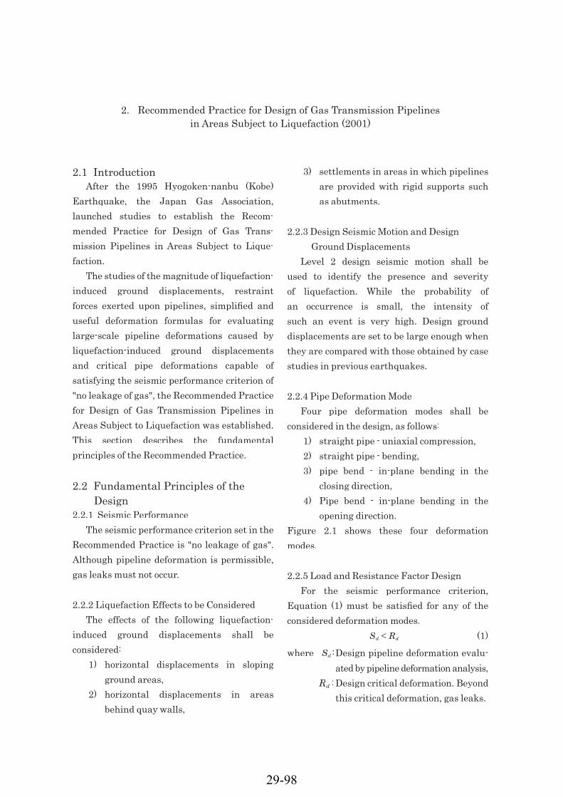
2.1 IntroductionAfter the 1995 Hyogoken-nanbu (Kobe)
Earthquake, the Japan Gas Association, launched studies to establish the Recom-mended Practice for Design of Gas Trans-mission Pipelines in Areas Subject to Lique-faction.
The studies of the magnitude of liquefaction-induced ground displacements, restraint forces exerted upon pipelines, simplifi ed and useful deformation formulas for evaluating large-scale pipeline deformations caused by liquefaction-induced ground displacements and critical pipe deformations capable of satisfying the seismic performance criterion of "no leakage of gas", the Recommended Practice for Design of Gas Transmission Pipelines in Areas Subject to Liquefaction was established. This section describes the fundamental principles of the Recommended Practice.
2.2 Fundamental Principles of the Design
2.2.1 Seismic PerformanceThe seismic performance criterion set in the
Recommended Practice is "no leakage of gas". Although pipeline deformation is permissible, gas leaks must not occur.
2.2.2 Liquefaction Effects to be ConsideredThe effects of the following liquefaction-
induced ground displacements shall be considered:
1) horizontal displacements in sloping ground areas,
2) horizontal displacements in areas behind quay walls,
3) settlements in areas in which pipelines are provided with rigid supports such as abutments.
2.2.3 Design Seismic Motion and Design Ground Displacements
Level 2 design seismic motion shall be used to identify the presence and severity of liquefaction. While the probability of an occurrence is small, the intensity of such an event is very high. Design ground displacements are set to be large enough when they are compared with those obtained by case studies in previous earthquakes.
2.2.4 Pipe Deformation ModeFour pipe deformation modes shall be
considered in the design, as follows:1) straight pipe - uniaxial compression,2) straight pipe - bending,3) pipe bend - in-plane bending in the
closing direction,4) Pipe bend - in-plane bending in the
opening direction.Figure 2.1 shows these four deformation modes.
2.2.5 Load and Resistance Factor DesignFor the seismic performance criterion,
Equation (1) must be satisfi ed for any of the considered deformation modes. Sd ≤ Rd (1)
where Sd :Design pipeline deformation evalu-ated by pipeline deformation analysis,
Rd :Design critical deformation. Beyond this critical deformation, gas leaks.
2. Recommended Practice for Design of Gas Transmission Pipelines in Areas Subject to Liquefaction (2001)
29-98

The Load and Resistance Factor Design was adopted to ensure appropriate safety margins and to facilitate the incorporation of future study and understanding into the Recommended Practice. In this design
methodology, a safety margin is assigned to each individual design component in the form of a partial safety factor, as is shown in Equation (2) and Equation (3). Figure 2.2 shows the design fl ow diagram.
where S(*): Function used to evaluate design pipeline deformation.δ: Liquefaction-induced ground displacement.L: Length of the area in which liquefaction-induced ground displacements occur.K: Restraint force exerted upon pipelines due to liquefaction-induced ground
displacements.R(*) : Function used to evaluate design critical pipe deformation.εu: Critical pipe strain. Beyond this critical strain, gas leaks occur.γ∗ : Partial safety factor.
Sd=γα・S(γδ・δ, L,γK・K)K)K (2) Rd = R (εR (εR ( u /γm)/γb (3)
Figure 2.1 The deformation modes for straight pipes and pipe bends
29-99
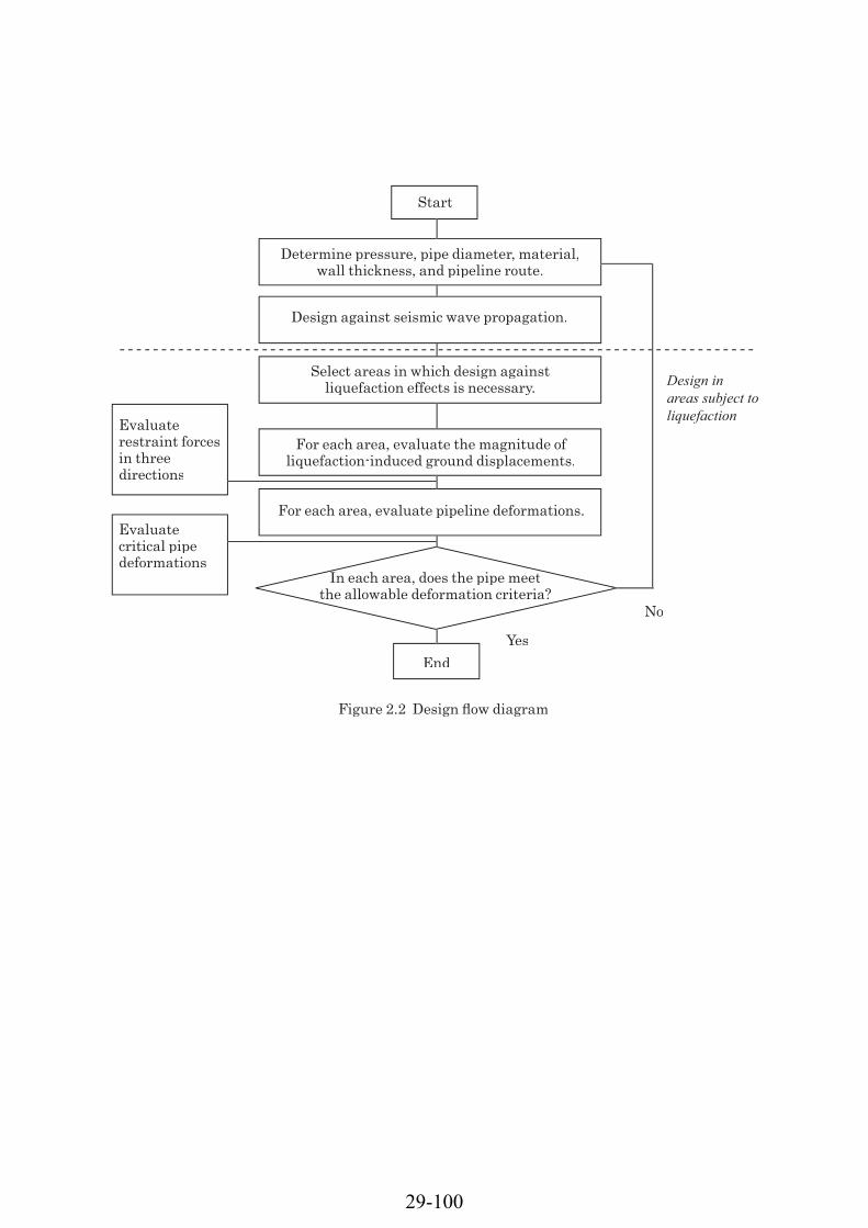
Start
Determine pressure, pipe diameter, material,wall thickness, and pipeline route.
Design against seismic wave propagation.
Select areas in which design against liquefaction effects is necessary.
For each area, evaluate the magnitude ofliquefaction-induced ground displacements.
For each area, evaluate pipeline deformations.
In each area, does the pipe meetthe allowable deformation criteria?
End
Figure 2.2 Design fl ow diagram
Evaluaterestraint forces in three directions
Evaluate critical pipedeformations
Design in areas subject to liquefaction
No
Yes
29-100