seismic performance of high-rise buildings featuring a
TRANSCRIPT
Australian Earthquake Engineering Society 2016 Conference, Nov 25-27, Melbourne, Vic
1
Seismic performance of high-rise buildings featuring a transfer plate taking into account displacement-
controlled behaviour
Mehair Yacoubian1, Nelson Lam2, Elisa Lumantarna3 John L. Wilson4
1. Corresponding Author, PhD candidate, Department of Infrastructure Engineering, The University of Melbourne, Parkville, VIC 3010, Australia.
Email: [email protected]
2. Associate Professor and Reader, Department of Infrastructure Engineering, The University of Melbourne, Parkville, VIC 3010, Australia.
Email: [email protected]
3. Lecturer, Department of Infrastructure Engineering, University of Melbourne, Parkville, VIC 3010, Australia. Email: [email protected]
4. Professor, Centre for Sustainable Infrastructure, Swinburne University of Technology, Hawthorn, VIC 3122. Email: [email protected]
Abstract Displacement-controlled behaviour has significant implications on high rise buildings because the displacement demand on the structural members (walls, columns and slabs) can be bounded by the peak displacement demand of the earthquake. This paper expands on current understanding of the seismic performance behaviour of transfer structures in buildings. Notably, drift demands on structural walls above the level of the transfer plate are examined in the light of displacement-controlled principles. Strutting compatibility forces in the floor slabs above the transfer level are the direct consequence of incompatible imposed deformations. These forces are displacement-controlled and have significant influences on the amount of differential deformation of the connecting floor slabs (and the coupling beams). Elaborate models are examined to showcase the consequences of diaphragm flexibility on the seismic performance of the building and specifically the shear demands on the tower walls.
Keywords: displacement-controlled behaviour, transfer structures, diaphragm flexibility, brittle shear failure.
Australian Earthquake Engineering Society 2016 Conference, Nov 25-27, Melbourne, Vic
2
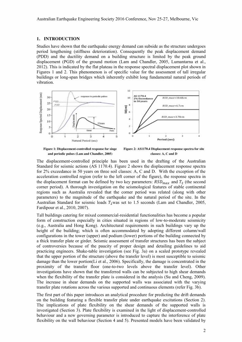
1. INTRODUCTION Studies have shown that the earthquake energy demand can subside as the structure undergoes period lengthening (stiffness deterioration). Consequently the peak displacement demand (PDD) and the ductility demand on a building structure is limited by the peak ground displacement (PGD) of the ground motion (Lam and Chandler, 2005, Lumantarna et al., 2012). This is indicated by the flat plateau in the response spectral displacement plot shown in Figures 1 and 2. This phenomenon is of specific value for the assessment of tall irregular buildings or long-span bridges which inherently exhibit long fundamental natural periods of vibration.
Figure 1: Displacement-controlled response for singe
and periodic pulses (Lam and Chandler, 2005) Figure 2: AS1170.4 Displacement response spectra for site
classes: A, C and D
The displacement-controlled principle has been used in the drafting of the Australian Standard for seismic actions (AS 1170.4). Figure 2 shows the displacement response spectra for 2% exceedance in 50 years on three soil classes: A, C and D. With the exception of the acceleration controlled region (refer to the left corner of the figure), the response spectra in the displacement format can be defined by two key parameters: 𝑅𝑆𝐷𝑚𝑎𝑥 and 𝑇2 (the second corner period). A thorough investigation on the seismological features of stable continental regions such as Australia revealed that the corner period was related (along with other parameters) to the magnitude of the earthquake and the natural period of the site. In the Australian Standard for seismic loads 𝑇2was set to 1.5 seconds (Lam and Chandler, 2005, Fardipour et al., 2010, 2007).
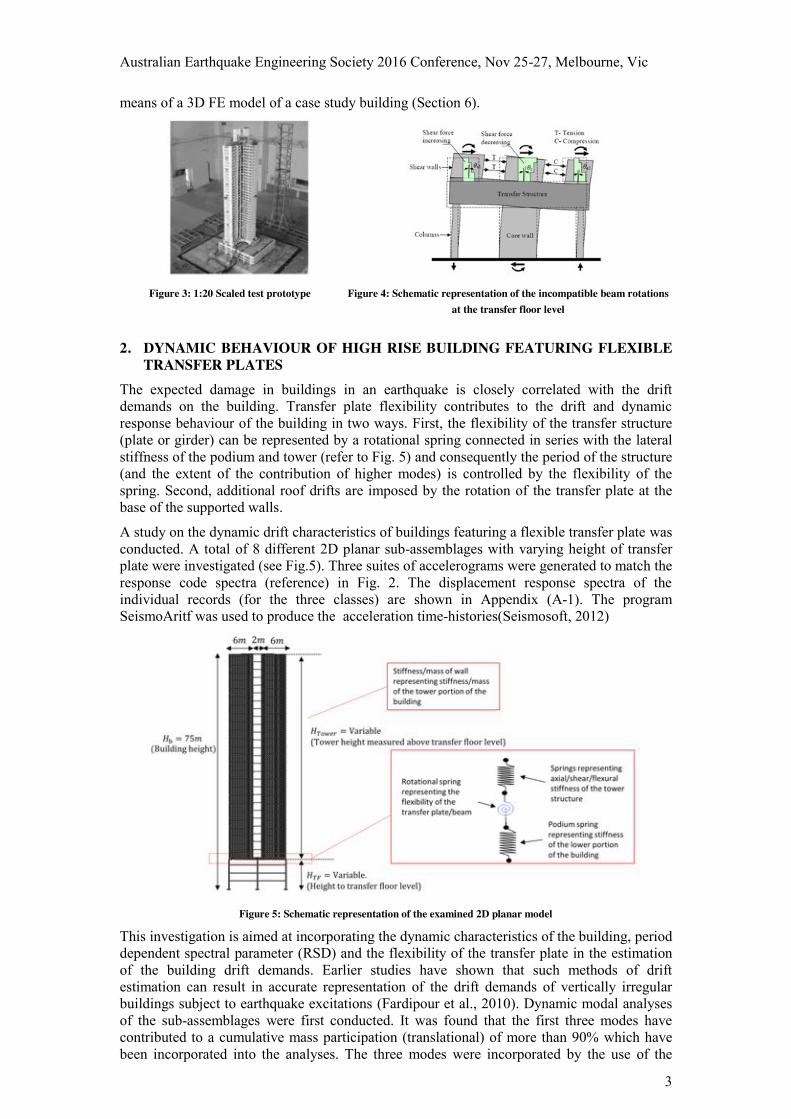
Tall buildings catering for mixed commercial-residential functionalities has become a popular form of construction especially in cities situated in regions of low-to-moderate seismicity (e.g., Australia and Hong Kong). Architectural requirements in such buildings vary up the height of the building; which is often accommodated by adopting different column/wall configurations in the tower (upper) and podium (lower) portions of the building connected by a thick transfer plate or girder. Seismic assessment of transfer structures has been the subject of controversies because of the paucity of proper design and detailing guidelines to aid practicing engineers. Shake-table investigation (see Fig. 3a) on a scaled prototype revealed that the upper portion of the structure (above the transfer level) is most susceptible to seismic damage than the lower portion(Li et al., 2006). Specifically, the damage is concentrated in the proximity of the transfer floor (one-to-two levels above the transfer level). Other investigations have shown that the transferred walls can be subjected to high shear demands when the flexibility of the transfer plate is considered in the analysis (Su and Cheng, 2009). The increase in shear demands on the supported walls was associated with the varying transfer plate rotations across the various supported and continuous elements (refer Fig. 3b).
The first part of this paper introduces an analytical procedure for predicting the drift demands on the building featuring a flexible transfer plate under earthquake excitations (Section 2). The implications of plate flexibility on the shear demands of the supported walls is investigated (Section 3). Plate flexibility is examined in the light of displacement-controlled behaviour and a new governing parameter is introduced to capture the interference of plate flexibility on the wall behaviour (Section 4 and 5). Presented models have been validated by
Australian Earthquake Engineering Society 2016 Conference, Nov 25-27, Melbourne, Vic
3
means of a 3D FE model of a case study building (Section 6).
Figure 3: 1:20 Scaled test prototype Figure 4: Schematic representation of the incompatible beam rotations
at the transfer floor level
2. DYNAMIC BEHAVIOUR OF HIGH RISE BUILDING FEATURING FLEXIBLE TRANSFER PLATES
The expected damage in buildings in an earthquake is closely correlated with the drift demands on the building. Transfer plate flexibility contributes to the drift and dynamic response behaviour of the building in two ways. First, the flexibility of the transfer structure (plate or girder) can be represented by a rotational spring connected in series with the lateral stiffness of the podium and tower (refer to Fig. 5) and consequently the period of the structure (and the extent of the contribution of higher modes) is controlled by the flexibility of the spring. Second, additional roof drifts are imposed by the rotation of the transfer plate at the base of the supported walls.
A study on the dynamic drift characteristics of buildings featuring a flexible transfer plate was conducted. A total of 8 different 2D planar sub-assemblages with varying height of transfer plate were investigated (see Fig.5). Three suites of accelerograms were generated to match the response code spectra (reference) in Fig. 2. The displacement response spectra of the individual records (for the three classes) are shown in Appendix (A-1). The program SeismoAritf was used to produce the acceleration time-histories(Seismosoft, 2012)
Figure 5: Schematic representation of the examined 2D planar model
This investigation is aimed at incorporating the dynamic characteristics of the building, period dependent spectral parameter (RSD) and the flexibility of the transfer plate in the estimation of the building drift demands. Earlier studies have shown that such methods of drift estimation can result in accurate representation of the drift demands of vertically irregular buildings subject to earthquake excitations (Fardipour et al., 2010). Dynamic modal analyses of the sub-assemblages were first conducted. It was found that the first three modes have contributed to a cumulative mass participation (translational) of more than 90% which have been incorporated into the analyses. The three modes were incorporated by the use of the
Australian Earthquake Engineering Society 2016 Conference, Nov 25-27, Melbourne, Vic
4
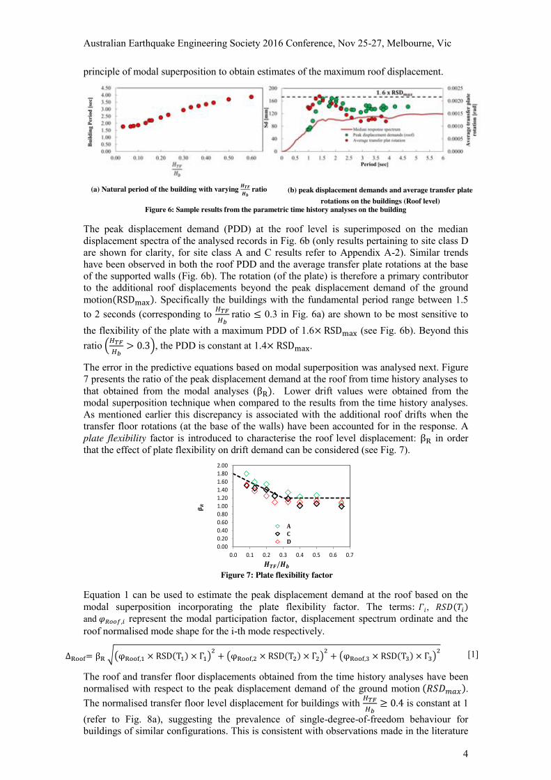
principle of modal superposition to obtain estimates of the maximum roof displacement.
(a) Natural period of the building with varying 𝑯𝑻𝑭
𝑯𝒃 ratio (b) peak displacement demands and average transfer plate
rotations on the buildings (Roof level) Figure 6: Sample results from the parametric time history analyses on the building
The peak displacement demand (PDD) at the roof level is superimposed on the median displacement spectra of the analysed records in Fig. 6b (only results pertaining to site class D are shown for clarity, for site class A and C results refer to Appendix A-2). Similar trends have been observed in both the roof PDD and the average transfer plate rotations at the base of the supported walls (Fig. 6b). The rotation (of the plate) is therefore a primary contributor to the additional roof displacements beyond the peak displacement demand of the ground motion(RSDmax). Specifically the buildings with the fundamental period range between 1.5 to 2 seconds (corresponding to 𝐻𝑇𝐹
𝐻𝑏 ratio ≤ 0.3 in Fig. 6a) are shown to be most sensitive to
the flexibility of the plate with a maximum PDD of 1.6× RSDmax (see Fig. 6b). Beyond this ratio (𝐻𝑇𝐹
𝐻𝑏> 0.3), the PDD is constant at 1.4× RSDmax.
The error in the predictive equations based on modal superposition was analysed next. Figure 7 presents the ratio of the peak displacement demand at the roof from time history analyses to that obtained from the modal analyses (βR). Lower drift values were obtained from the modal superposition technique when compared to the results from the time history analyses. As mentioned earlier this discrepancy is associated with the additional roof drifts when the transfer floor rotations (at the base of the walls) have been accounted for in the response. A plate flexibility factor is introduced to characterise the roof level displacement: βR in order that the effect of plate flexibility on drift demand can be considered (see Fig. 7).
Figure 7: Plate flexibility factor
Equation 1 can be used to estimate the peak displacement demand at the roof based on the modal superposition incorporating the plate flexibility factor. The terms: 𝛤𝑖, 𝑅𝑆𝐷(𝑇𝑖) and 𝜑𝑅𝑜𝑜𝑓,𝑖 represent the modal participation factor, displacement spectrum ordinate and the roof normalised mode shape for the i-th mode respectively.
∆Roof= βR √(φRoof,1 × RSD(T1) × Γ1)2 + (φRoof,2 × RSD(T2) × Γ2)2 + (φRoof,3 × RSD(T3) × Γ3)2 [1]
The roof and transfer floor displacements obtained from the time history analyses have been normalised with respect to the peak displacement demand of the ground motion (𝑅𝑆𝐷𝑚𝑎𝑥). The normalised transfer floor level displacement for buildings with 𝐻𝑇𝐹
𝐻𝑏≥ 0.4 is constant at 1
(refer to Fig. 8a), suggesting the prevalence of single-degree-of-freedom behaviour for buildings of similar configurations. This is consistent with observations made in the literature
0.000.200.400.600.801.001.201.401.601.802.00
0.0 0.1 0.2 0.3 0.4 0.5 0.6 0.7
ACD
0.000.200.400.600.801.001.201.401.601.802.00
0.0 0.1 0.2 0.3 0.4 0.5 0.6 0.7
Australian Earthquake Engineering Society 2016 Conference, Nov 25-27, Melbourne, Vic
5
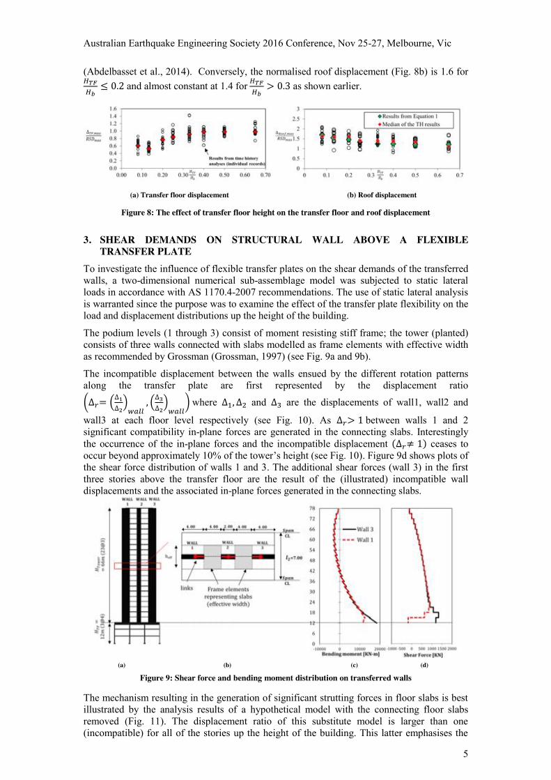
(Abdelbasset et al., 2014). Conversely, the normalised roof displacement (Fig. 8b) is 1.6 for 𝐻𝑇𝐹𝐻𝑏
≤ 0.2 and almost constant at 1.4 for 𝐻𝑇𝐹𝐻𝑏
> 0.3 as shown earlier.
(a) Transfer floor displacement (b) Roof displacement
Figure 8: The effect of transfer floor height on the transfer floor and roof displacement
3. SHEAR DEMANDS ON STRUCTURAL WALL ABOVE A FLEXIBLE TRANSFER PLATE
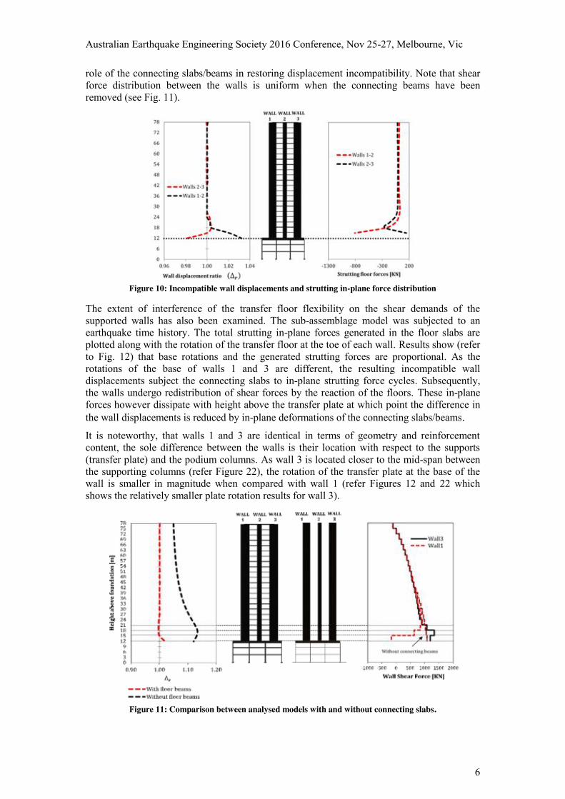
To investigate the influence of flexible transfer plates on the shear demands of the transferred walls, a two-dimensional numerical sub-assemblage model was subjected to static lateral loads in accordance with AS 1170.4-2007 recommendations. The use of static lateral analysis is warranted since the purpose was to examine the effect of the transfer plate flexibility on the load and displacement distributions up the height of the building.
The podium levels (1 through 3) consist of moment resisting stiff frame; the tower (planted) consists of three walls connected with slabs modelled as frame elements with effective width as recommended by Grossman (Grossman, 1997) (see Fig. 9a and 9b).
The incompatible displacement between the walls ensued by the different rotation patterns along the transfer plate are first represented by the displacement ratio
(∆𝑟= (∆1∆2
)𝑤𝑎𝑙𝑙
, (∆3∆2
)𝑤𝑎𝑙𝑙
) where ∆1, ∆2 and ∆3 are the displacements of wall1, wall2 and
wall3 at each floor level respectively (see Fig. 10). As ∆𝑟> 1 between walls 1 and 2 significant compatibility in-plane forces are generated in the connecting slabs. Interestingly the occurrence of the in-plane forces and the incompatible displacement (∆𝑟≠ 1) ceases to occur beyond approximately 10% of the tower’s height (see Fig. 10). Figure 9d shows plots of the shear force distribution of walls 1 and 3. The additional shear forces (wall 3) in the first three stories above the transfer floor are the result of the (illustrated) incompatible wall displacements and the associated in-plane forces generated in the connecting slabs.
(a) (b) (c) (d)
Figure 9: Shear force and bending moment distribution on transferred walls
The mechanism resulting in the generation of significant strutting forces in floor slabs is best illustrated by the analysis results of a hypothetical model with the connecting floor slabs removed (Fig. 11). The displacement ratio of this substitute model is larger than one (incompatible) for all of the stories up the height of the building. This latter emphasises the
Australian Earthquake Engineering Society 2016 Conference, Nov 25-27, Melbourne, Vic
6
role of the connecting slabs/beams in restoring displacement incompatibility. Note that shear force distribution between the walls is uniform when the connecting beams have been removed (see Fig. 11).
Figure 10: Incompatible wall displacements and strutting in-plane force distribution
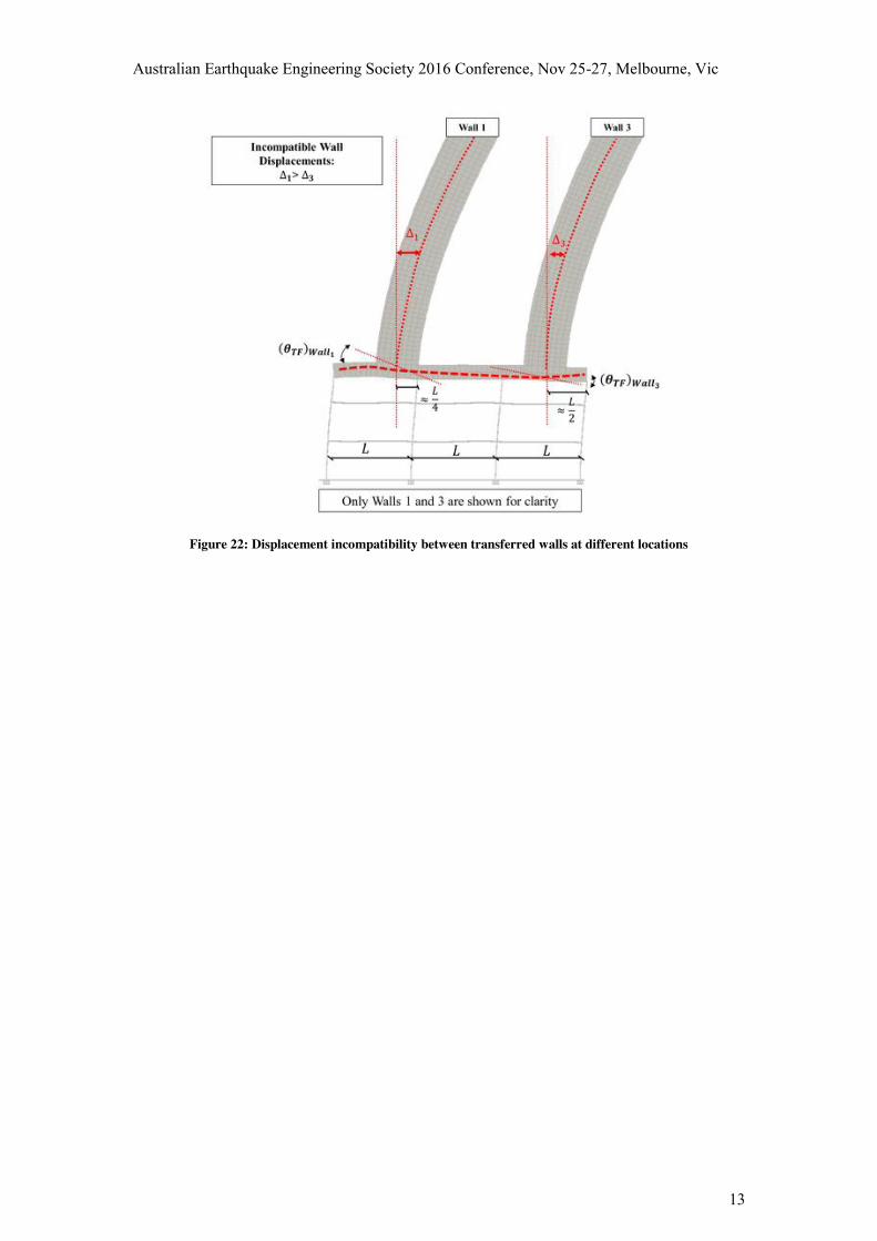
The extent of interference of the transfer floor flexibility on the shear demands of the supported walls has also been examined. The sub-assemblage model was subjected to an earthquake time history. The total strutting in-plane forces generated in the floor slabs are plotted along with the rotation of the transfer floor at the toe of each wall. Results show (refer to Fig. 12) that base rotations and the generated strutting forces are proportional. As the rotations of the base of walls 1 and 3 are different, the resulting incompatible wall displacements subject the connecting slabs to in-plane strutting force cycles. Subsequently, the walls undergo redistribution of shear forces by the reaction of the floors. These in-plane forces however dissipate with height above the transfer plate at which point the difference in the wall displacements is reduced by in-plane deformations of the connecting slabs/beams. It is noteworthy, that walls 1 and 3 are identical in terms of geometry and reinforcement content, the sole difference between the walls is their location with respect to the supports (transfer plate) and the podium columns. As wall 3 is located closer to the mid-span between the supporting columns (refer Figure 22), the rotation of the transfer plate at the base of the wall is smaller in magnitude when compared with wall 1 (refer Figures 12 and 22 which shows the relatively smaller plate rotation results for wall 3).
Figure 11: Comparison between analysed models with and without connecting slabs.
Australian Earthquake Engineering Society 2016 Conference, Nov 25-27, Melbourne, Vic
7
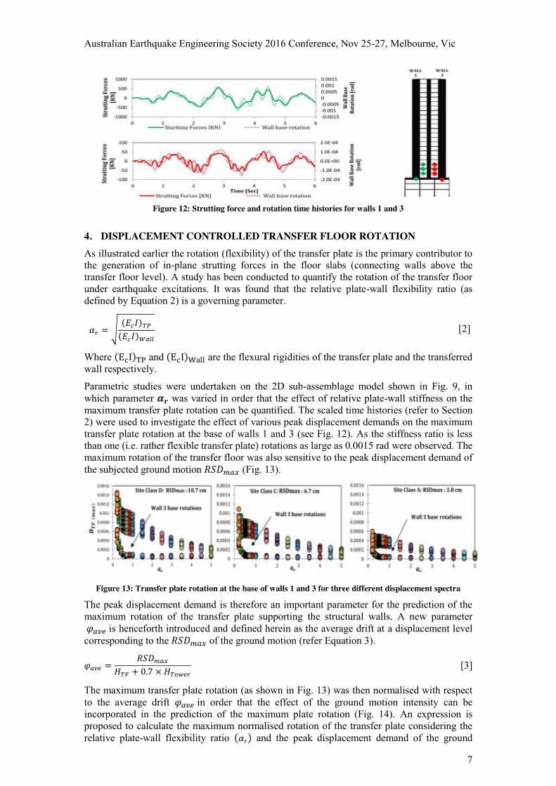
Figure 12: Strutting force and rotation time histories for walls 1 and 3
4. DISPLACEMENT CONTROLLED TRANSFER FLOOR ROTATION As illustrated earlier the rotation (flexibility) of the transfer plate is the primary contributor to the generation of in-plane strutting forces in the floor slabs (connecting walls above the transfer floor level). A study has been conducted to quantify the rotation of the transfer floor under earthquake excitations. It was found that the relative plate-wall flexibility ratio (as defined by Equation 2) is a governing parameter.
𝛼𝑟 = √(𝐸𝑐𝐼)𝑇𝑃
(𝐸𝑐𝐼)𝑊𝑎𝑙𝑙 [2]
Where (EcI)TP and (EcI)Wall are the flexural rigidities of the transfer plate and the transferred wall respectively.
Parametric studies were undertaken on the 2D sub-assemblage model shown in Fig. 9, in which parameter 𝜶𝒓 was varied in order that the effect of relative plate-wall stiffness on the maximum transfer plate rotation can be quantified. The scaled time histories (refer to Section 2) were used to investigate the effect of various peak displacement demands on the maximum transfer plate rotation at the base of walls 1 and 3 (see Fig. 12). As the stiffness ratio is less than one (i.e. rather flexible transfer plate) rotations as large as 0.0015 rad were observed. The maximum rotation of the transfer floor was also sensitive to the peak displacement demand of the subjected ground motion 𝑅𝑆𝐷𝑚𝑎𝑥 (Fig. 13).
Figure 13: Transfer plate rotation at the base of walls 1 and 3 for three different displacement spectra
The peak displacement demand is therefore an important parameter for the prediction of the maximum rotation of the transfer plate supporting the structural walls. A new parameter 𝜑𝑎𝑣𝑒 is henceforth introduced and defined herein as the average drift at a displacement level corresponding to the 𝑅𝑆𝐷𝑚𝑎𝑥 of the ground motion (refer Equation 3).
𝜑𝑎𝑣𝑒 =𝑅𝑆𝐷𝑚𝑎𝑥
𝐻𝑇𝐹 + 0.7 × 𝐻𝑇𝑜𝑤𝑒𝑟 [3]
The maximum transfer plate rotation (as shown in Fig. 13) was then normalised with respect to the average drift 𝜑𝑎𝑣𝑒 in order that the effect of the ground motion intensity can be incorporated in the prediction of the maximum plate rotation (Fig. 14). An expression is proposed to calculate the maximum normalised rotation of the transfer plate considering the relative plate-wall flexibility ratio (𝛼𝑟) and the peak displacement demand of the ground
Australian Earthquake Engineering Society 2016 Conference, Nov 25-27, Melbourne, Vic
8
motion (φave):
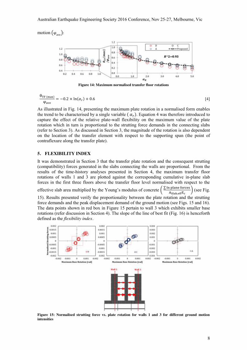
Figure 14: Maximum normalised transfer floor rotations
θTF (max)
φave= −0.2 × ln(𝛼𝑟) + 0.6 [4]
As illustrated in Fig. 14, presenting the maximum plate rotation in a normalised form enables the trend to be characterised by a single variable ( 𝛼𝑟). Equation 4 was therefore introduced to capture the effect of the relative plate-wall flexibility on the maximum value of the plate rotation which in turn is proportional to the strutting force demands in the connecting slabs (refer to Section 3). As discussed in Section 3, the magnitude of the rotation is also dependent on the location of the transfer element with respect to the supporting span (the point of contraflexure along the transfer plate).
5. FLEXIBILITY INDEX It was demonstrated in Section 3 that the transfer plate rotation and the consequent strutting (compatibility) forces generated in the slabs connecting the walls are proportional. From the results of the time-history analyses presented in Section 4, the maximum transfer floor rotations of walls 1 and 3 are plotted against the corresponding cumulative in-plane slab forces in the first three floors above the transfer floor level normalised with respect to the
effective slab area multiplied by the Young’s modulus of concrete ( ∑ In plane forces ASlab,effEc
) (see Fig.
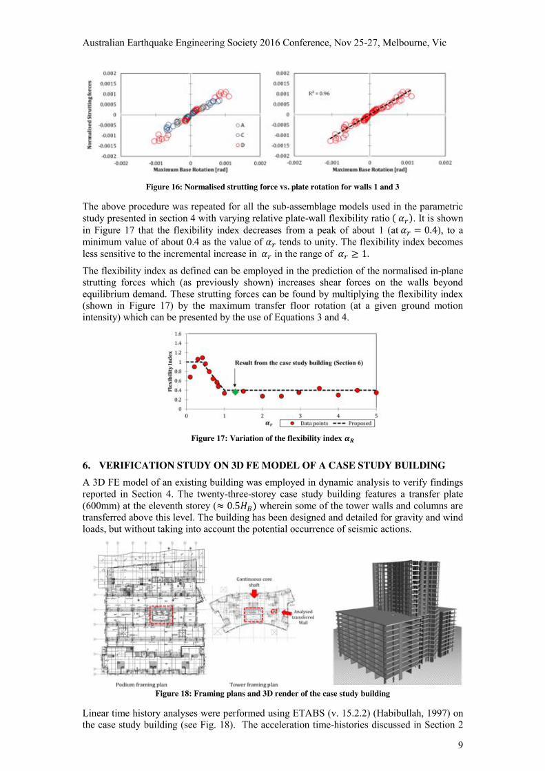
15). Results presented verify the proportionality between the plate rotation and the strutting force demands and the peak displacement demand of the ground motion (see Figs. 15 and 16). The data points shown in red box in Figure 15 pertain to wall 3 which exhibits smaller base rotations (refer discussion in Section 4). The slope of the line of best fit (Fig. 16) is henceforth defined as the flexibility index.
Figure 15: Normalised strutting force vs. plate rotation for walls 1 and 3 for different ground motion intensities
Australian Earthquake Engineering Society 2016 Conference, Nov 25-27, Melbourne, Vic
9
Figure 16: Normalised strutting force vs. plate rotation for walls 1 and 3
The above procedure was repeated for all the sub-assemblage models used in the parametric study presented in section 4 with varying relative plate-wall flexibility ratio ( 𝛼𝑟). It is shown in Figure 17 that the flexibility index decreases from a peak of about 1 (at 𝛼𝑟 = 0.4), to a minimum value of about 0.4 as the value of 𝛼𝑟 tends to unity. The flexibility index becomes less sensitive to the incremental increase in 𝛼𝑟 in the range of 𝛼𝑟 ≥ 1.
The flexibility index as defined can be employed in the prediction of the normalised in-plane strutting forces which (as previously shown) increases shear forces on the walls beyond equilibrium demand. These strutting forces can be found by multiplying the flexibility index (shown in Figure 17) by the maximum transfer floor rotation (at a given ground motion intensity) which can be presented by the use of Equations 3 and 4.
Figure 17: Variation of the flexibility index 𝜶𝑹
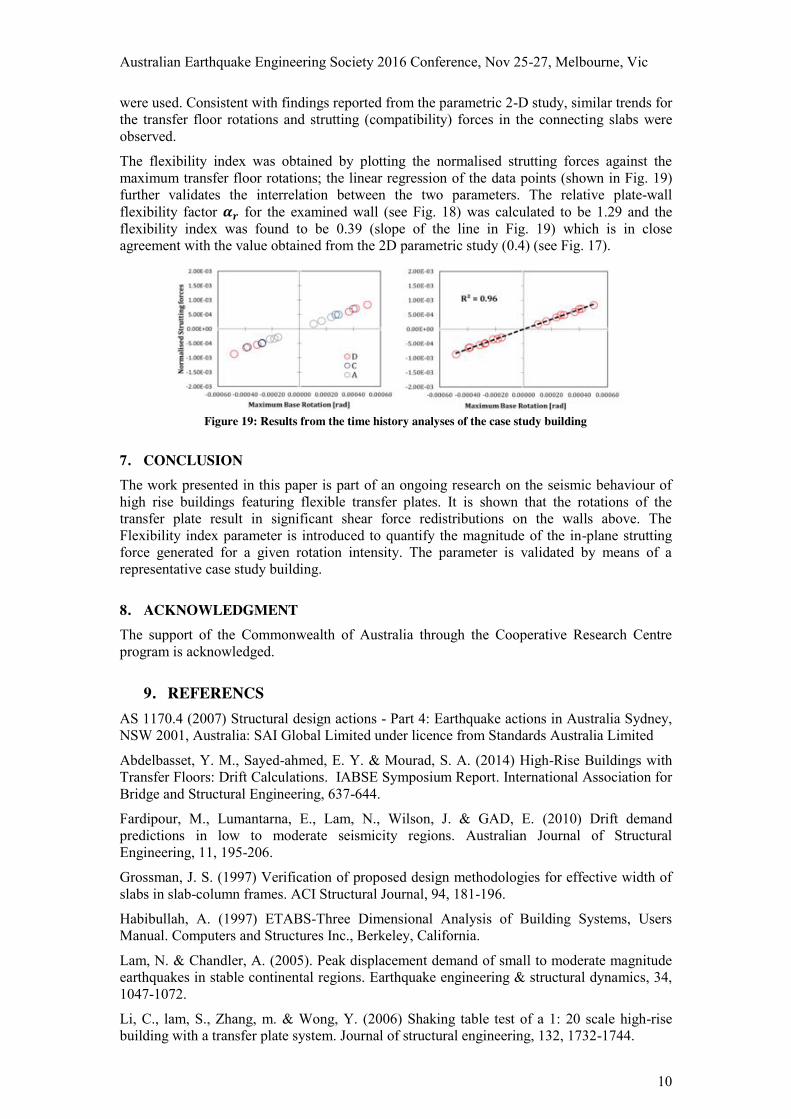
6. VERIFICATION STUDY ON 3D FE MODEL OF A CASE STUDY BUILDING A 3D FE model of an existing building was employed in dynamic analysis to verify findings reported in Section 4. The twenty-three-storey case study building features a transfer plate (600mm) at the eleventh storey (≈ 0.5𝐻𝐵) wherein some of the tower walls and columns are transferred above this level. The building has been designed and detailed for gravity and wind loads, but without taking into account the potential occurrence of seismic actions.
Figure 18: Framing plans and 3D render of the case study building
Linear time history analyses were performed using ETABS (v. 15.2.2) (Habibullah, 1997) on the case study building (see Fig. 18). The acceleration time-histories discussed in Section 2
Australian Earthquake Engineering Society 2016 Conference, Nov 25-27, Melbourne, Vic
10
were used. Consistent with findings reported from the parametric 2-D study, similar trends for the transfer floor rotations and strutting (compatibility) forces in the connecting slabs were observed.
The flexibility index was obtained by plotting the normalised strutting forces against the maximum transfer floor rotations; the linear regression of the data points (shown in Fig. 19) further validates the interrelation between the two parameters. The relative plate-wall flexibility factor 𝜶𝒓 for the examined wall (see Fig. 18) was calculated to be 1.29 and the flexibility index was found to be 0.39 (slope of the line in Fig. 19) which is in close agreement with the value obtained from the 2D parametric study (0.4) (see Fig. 17).
Figure 19: Results from the time history analyses of the case study building
7. CONCLUSION The work presented in this paper is part of an ongoing research on the seismic behaviour of high rise buildings featuring flexible transfer plates. It is shown that the rotations of the transfer plate result in significant shear force redistributions on the walls above. The Flexibility index parameter is introduced to quantify the magnitude of the in-plane strutting force generated for a given rotation intensity. The parameter is validated by means of a representative case study building.
8. ACKNOWLEDGMENT The support of the Commonwealth of Australia through the Cooperative Research Centre program is acknowledged.
9. REFERENCS AS 1170.4 (2007) Structural design actions - Part 4: Earthquake actions in Australia Sydney, NSW 2001, Australia: SAI Global Limited under licence from Standards Australia Limited
Abdelbasset, Y. M., Sayed-ahmed, E. Y. & Mourad, S. A. (2014) High-Rise Buildings with Transfer Floors: Drift Calculations. IABSE Symposium Report. International Association for Bridge and Structural Engineering, 637-644.
Fardipour, M., Lumantarna, E., Lam, N., Wilson, J. & GAD, E. (2010) Drift demand predictions in low to moderate seismicity regions. Australian Journal of Structural Engineering, 11, 195-206.
Grossman, J. S. (1997) Verification of proposed design methodologies for effective width of slabs in slab-column frames. ACI Structural Journal, 94, 181-196.
Habibullah, A. (1997) ETABS-Three Dimensional Analysis of Building Systems, Users Manual. Computers and Structures Inc., Berkeley, California.
Lam, N. & Chandler, A. (2005). Peak displacement demand of small to moderate magnitude earthquakes in stable continental regions. Earthquake engineering & structural dynamics, 34, 1047-1072.
Li, C., lam, S., Zhang, m. & Wong, Y. (2006) Shaking table test of a 1: 20 scale high-rise building with a transfer plate system. Journal of structural engineering, 132, 1732-1744.

Australian Earthquake Engineering Society 2016 Conference, Nov 25-27, Melbourne, Vic
11
Lumantarna, E., Lam, N. & Wilson, J. (2012) Seismic Assessment of Structures in Regions of Low to Moderate Seismicity. Civil Engineering Dimension, 14, 156-165.
Seismosoft, L. 2012. SeismoArtif. Pavia, Italy.
Su, R. & Cheng, M. (2009) Earthquake‐induced shear concentration in shear walls above transfer structures. The Structural Design of Tall and Special Buildings, 18, 657-671.
Australian Earthquake Engineering Society 2016 Conference, Nov 25-27, Melbourne, Vic
12
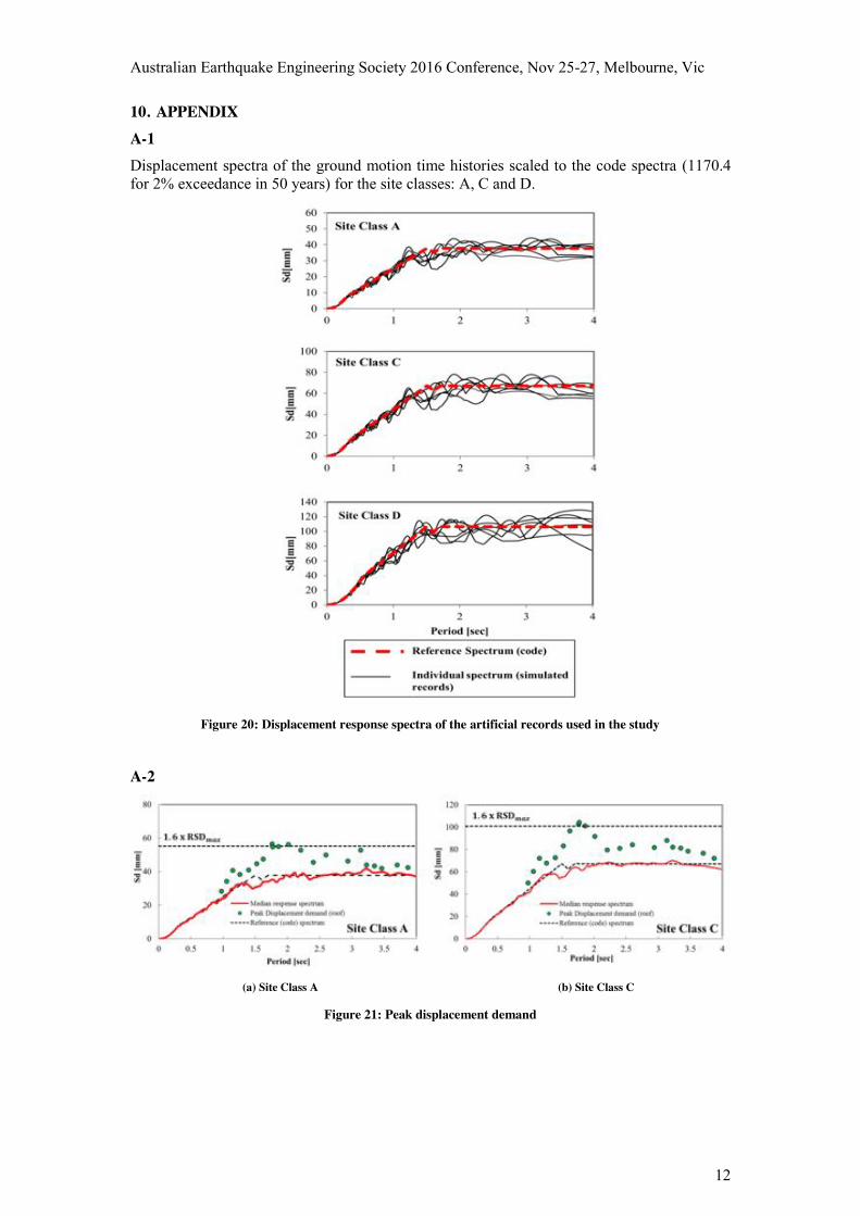
10. APPENDIX A-1 Displacement spectra of the ground motion time histories scaled to the code spectra (1170.4 for 2% exceedance in 50 years) for the site classes: A, C and D.
Figure 20: Displacement response spectra of the artificial records used in the study
A-2
(a) Site Class A (b) Site Class C
Figure 21: Peak displacement demand
Australian Earthquake Engineering Society 2016 Conference, Nov 25-27, Melbourne, Vic
13
Figure 22: Displacement incompatibility between transferred walls at different locations