seismic performance of high rise flat … · to determine the better lateral load resisting system...
TRANSCRIPT

International Research Journal of Engineering and Technology (IRJET) e-ISSN: 2395-0056
Volume: 05 Issue: 01 | Jan-2018 www.irjet.net p-ISSN: 2395-0072
© 2018, IRJET | Impact Factor value: 6.171 | ISO 9001:2008 Certified Journal | Page 849
SEISMIC PERFORMANCE OF HIGH RISE FLAT SLAB BUILDING WITH VARIOUS LATERAL LOAD RESISTING SYSTEMS
Pooja Biradar1, Kishor Kulkarni2, Nikhil Jamble2
1Post graduate student in structural engineering, KLEMSSCET, belagavi, Karnatka, India 2Assistant Professor, Dept. of Civil Engg, KLEMSSCET, Karnataka, India
---------------------------------------------------------------------***---------------------------------------------------------------------Abstract – In modern era, the construction of flat slab building is increasing everywhere, due to its major advantages such as architectural flexibility and lesser cost of construction. The use of flat slab in high seismic area is a risk as it is not efficient in resisting lateral loads. The study is considered about increase in lateral load carrying capacity of building by using shear walls, perimeter beams and bracing system. In this study 15 storied flat slab building is analyzed for different lateral load resisting system using time history method. For the time history method, realistic BHUJ earthquake data is used and analysis is carried out by commercially available software ‘ETABs v9i’. The comparison of different lateral load resisting system (LLRS) is made by using various parameter such as maximum storey displacement, storey drift, time period and base shear.
Key Words: Flat Slab, Shear Wall, Bracings, Mode Shapes.
1. INTRODUCTION
India is a developing country and there is a huge growth in infrastructure development. As the population of India is increasing day by day there is high demand of land for construction. Since, most of the land is preserved for agriculture and farming, there is need for space for human dwelling hence development in vertical construction is necessary. Nowadays there is increase in number of tall buildings which are used for both commercial and residential purposes. When the height of the building increases it is important to counteract the lateral forces such as seismic and wind forces acting on the building. Normally the buildings are designed to counteract the gravity loads acting on it and to attain required strength and stability. Usually buildings are designed to resist gravity loads such as dead loads and live loads but other than these other loads acting laterally on the building such as earthquake and wind loads which may also act on it. To resist these lateral loads extra Lateral Load Resisting System (LLRS) is to be included in tall buildings. Lateral loads can develop high stresses and large lateral displacement. Therefore, it is very important for the structure to have adequate stiffness to resist lateral force along with strength to resist gravity loads. In modern era, along with the construction of high rise building there is also need to emphasis on the aesthetic view of the building and lesser cost of construction along with architectural
flexibility. Hence modern trend is to construct high rise building with flat slab floor system. [1]
1.1 Objectives of Study Based on the literature the following objectives are proposed for the present study
To determine the better lateral load resisting system for high rise buildings with flat slabs under seismic effects.
To determine the variation in lateral displacement, story drift, time period and base shear by using various lateral load resisting systems.
2. STRUCTURAL MODELLING AND ANALYSIS
In the present study multistoried building with flat slab system is modeled and analyzed for seismic forces. The various parameters are considered to make it seismic resistance. The different locations of shear wall at different locations and combination of bracing and shear wall system. Eight models are considered for the study. The analysis is carried out using commercially available software ‘ETABS’ 9 vi. The details of multistoried flat slab building are given in Table 1. Figure 1 shows the plan of Reinforced Concrete (RC) flat slab building modeled in ETABS’ 9 vi.
Table 1: Details of multistoried flat slab building
Type of building Commercial building
Plan area 35mX35m
Storey height 3.75m
Total height of building 54.5m
Bays 5 bays in X and Y-direction
Spacing of bays 7m
Type of soil Type II( Medium soil)
Earthquake zone III
Location of building Pune

International Research Journal of Engineering and Technology (IRJET) e-ISSN: 2395-0056
Volume: 05 Issue: 01 | Jan-2018 www.irjet.net p-ISSN: 2395-0072
© 2018, IRJET | Impact Factor value: 6.171 | ISO 9001:2008 Certified Journal | Page 850
Fig. 1: Plan of the RC flat slab building
The properties of the material taken in the analysis and the details of gravity and seismic loadings are presented in Table 2. The flat slab and drop of the building designed for gravity loads as per code IS 456:2002[2] and the thickness of flat slab and drop are adopted as per the design are presented in Table 3. The size of column for different stories is given in Table 4.
Table 2: Material properties and loadings
Grade of concrete M25
Density of concrete 25 kN/m3
Grade of steel reinforcement Fe415
Grade of steel bracings Fe 250
Live load 3 kN/m2
Floors finish 1.5 kN/m2
Live load reduction factor 25%
Seismic zone factor 0.16
Response reduction factor 5
Importance factor 1
Table 3: Details of structural members
Slab thickness 0.2m
Drop thickness 0.1m
Diaphragm Rigid
Table 4: Column Dimensions
1st storey 1.2 m x1.2 m 2nd to 3rd storey 1 m x1m 4th to 6th storey 0.9 m x0.9 m 7th to 8th storey 0.75 m x 0.75 m 9th to 15th storey 0.68 m x 0.68 m
The description of various models used in the present investigation is presented in Table 5.
Table 5 Description of various models used
Description Notations
Flat slab building BF Flat slab building with centre shear wall CnSW
Flat slab building with corner shear wall CrSW Flat slab building with parallel shear wall PSW Flat slab building with centre and parallel shear wall
CnPSW
Flat slab building with centre and corner shear wall
CnCrSW
Flat slab building with centre shear wall and perimeter beams
CnSWPb
Flat slab building with bracings at exterior and centre shear wall
CnSWEb
For all the models length of shear wall is taken as 6 m in X and Y direction. Model 1 is the flat slab building with bare frame. Model 2 consists of flat slab building with channel shaped centre shear wall only. The plan of building with different locations of shear wall is shown in Fig 2. The thickness of shear wall is assumed to be 0.3 m. Model 6 consists of flat slab building with centre shear wall and perimeter beams. The Eighth model consist of centre shear wall and exterior bracing. Channel section (ISMC300) bracings considered for analysis.
Model 2 (CnSW) Model 3(CrSW)
Model 4 (PSW) Model 5 (CrPSW)

International Research Journal of Engineering and Technology (IRJET) e-ISSN: 2395-0056
Volume: 05 Issue: 01 | Jan-2018 www.irjet.net p-ISSN: 2395-0072
© 2018, IRJET | Impact Factor value: 6.171 | ISO 9001:2008 Certified Journal | Page 851
Model 6 (CrCnSW) Model 7 (CrSWPb)
Fig-2: Plan of various models used
Fig 3: Position of bracings in flat slab building with CnSWEb
2.1 Seismic Analysis The seismic analysis of the RC flat slab Multistoried building is carried out by linear time history method is used to determine the design lateral load. In this study the ‘Bhuj’ earthquake data is used for the time history analysis. Fig 3: shows the variation of acceleration v/s time for Bhuj earthquake data
Fig 3: Time history plot of Bhuj earthquake
3. RESULTS AND DISCUSSION This section presents the results on seismic performance of high rise flat slab RC structure subjected to lateral force
for various lateral load resisting systems. The results are presented in the form of storey displacement, storey drift, time period and base shear with respect to various LLRS.
3.1 Storey Displacement Storey displacement is found to be maximum for top stories where as the displacement goes on reducing for bottom stories. The results of storey displacement for various LLRS in X-direction and Y- direction. The variation in storey displacement with different LLRS is plotted in Chart 1 and Chart 2.
Chart 1: Storey displacement V/s LLRS
Chart 2: Storey displacement V/s LLRS The reduction in the storey displacement in Y direction is about 33%, 39%, 8%, 45%, 62% ,74% and 72% for CnSW, CrSW, PSW, CnPSW, CnCrSW, CnSWPb and CnSWEb respectively, as compared to bare frame. There is marginal change in storey displacement for CnSW and CnPSW lateral load resisting system as compared with X direction displacement. This is due to the presence of channel shaped shear wall placed at centre of the building which do not provide the adequate stiffness for resisting lateral forces in Y-direction Amongst all the LLRS centre shear wall with perimeter beam and centre shear wall with exterior bracing shown better performance under seismic force when compared to bare frame. This is probably due to, increase in stiffness of RC building, which helps in considerably reduction of lateral displacement under seismic force.
050
100150200250300350400450
Dis
pla
cem
en
t(m
m)
Lateral load resisting systems
050
100150200250300350400450
Dis
pla
cem
en
t(m
m)
Lateral load resisting systems
International Research Journal of Engineering and Technology (IRJET) e-ISSN: 2395-0056
Volume: 05 Issue: 01 | Jan-2018 www.irjet.net p-ISSN: 2395-0072
© 2018, IRJET | Impact Factor value: 6.171 | ISO 9001:2008 Certified Journal | Page 852
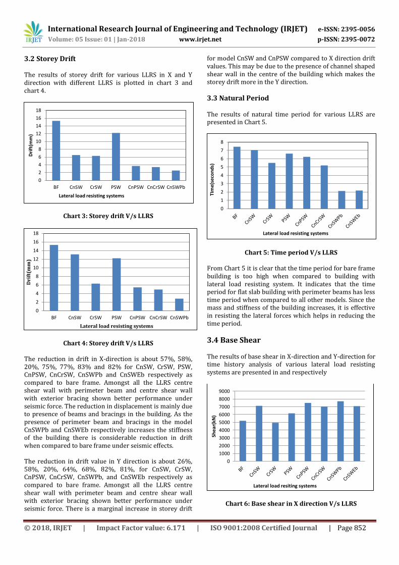
3.2 Storey Drift The results of storey drift for various LLRS in X and Y direction with different LLRS is plotted in chart 3 and chart 4.
Chart 3: Storey drift V/s LLRS
Chart 4: Storey drift V/s LLRS
The reduction in drift in X-direction is about 57%, 58%, 20%, 75%, 77%, 83% and 82% for CnSW, CrSW, PSW, CnPSW, CnCrSW, CnSWPb and CnSWEb respectively as compared to bare frame. Amongst all the LLRS centre shear wall with perimeter beam and centre shear wall with exterior bracing shown better performance under seismic force. The reduction in displacement is mainly due to presence of beams and bracings in the building. As the presence of perimeter beam and bracings in the model CnSWPb and CnSWEb respectively increases the stiffness of the building there is considerable reduction in drift when compared to bare frame under seismic effects. The reduction in drift value in Y direction is about 26%, 58%, 20%, 64%, 68%, 82%, 81%, for CnSW, CrSW, CnPSW, CnCrSW, CnSWPb, and CnSWEb respectively as compared to bare frame. Amongst all the LLRS centre shear wall with perimeter beam and centre shear wall with exterior bracing shown better performance under seismic force. There is a marginal increase in storey drift
for model CnSW and CnPSW compared to X direction drift values. This may be due to the presence of channel shaped shear wall in the centre of the building which makes the storey drift more in the Y direction.
3.3 Natural Period The results of natural time period for various LLRS are presented in Chart 5.
Chart 5: Time period V/s LLRS
From Chart 5 it is clear that the time period for bare frame building is too high when compared to building with lateral load resisting system. It indicates that the time period for flat slab building with perimeter beams has less time period when compared to all other models. Since the mass and stiffness of the building increases, it is effective in resisting the lateral forces which helps in reducing the time period.
3.4 Base Shear The results of base shear in X-direction and Y-direction for time history analysis of various lateral load resisting systems are presented in and respectively
Chart 6: Base shear in X direction V/s LLRS
0
2
4
6
8
10
12
14
16
18
BF CnSW CrSW PSW CnPSW CnCrSW CnSWPb
Dri
ft(m
m)
Lateral load resisting systems
0
2
4
6
8
10
12
14
16
18
BF CnSW CrSW PSW CnPSW CnCrSW CnSWPb
Dri
ft(m
m)
Lateral load resisting systems
0
1
2
3
4
5
6
7
8
TIm
e(se
con
ds)
Lateral load resisting systems
0
1000
2000
3000
4000
5000
6000
7000
8000
9000
Shea
r(kN
)
Lateral load resiting systems

International Research Journal of Engineering and Technology (IRJET) e-ISSN: 2395-0056
Volume: 05 Issue: 01 | Jan-2018 www.irjet.net p-ISSN: 2395-0072
© 2018, IRJET | Impact Factor value: 6.171 | ISO 9001:2008 Certified Journal | Page 853
Chart 7: Base shear in Y direction V/s LLRS
The average increase in base shear is about 48% and 36% for CnSWPb and CnSWEb respectively as compared to bare frame. This is due to the increase mass of the structure the base shear also increases. Similarly the increase in base shear is about 63% and 53% for CnSWPb and CnSWEb respectively as compared to bare frame. The increase in lateral force at the base of structure in Y direction when compared to Y direction base shear values may be due to the presence of channel shaped shear wall at centre of the building.
4. Conclusions The following conclusion are drawn from the present study,
The reduction in top storey displacement for flat slab building with centre shear wall and perimeter beams is about 74% when compared to bare frame. Hence the building with centre shear wall and perimeter beams is effective in reducing the lateral displacement.
The reduction in storey drift for flat slab building with centre shear wall and perimeter beams is about 83% when compared to bare frame. Hence the building with perimeter beams and centre shear wall effectively counteract the seismic forces and reduce the storey drift.
The time period for flat slab building without any LLRS is comparatively more than other buildings. The considerably reduction in time period is found for corner shear wall, perimeter beams and bracing load resisting system.
The natural time period for flat slab building with perimeter beams and centre shear wall is less amongst all lateral load resisting systems.
There is increase in base shear for flat slab building with perimeter beam and centre shear wall.
Among all the flat slab buildings with different LLRS the flat slab building with perimeter beam and centre shear wall shows better performance against seismic forces when compared to bare frame.
Lateral load resisting system with bracing shows better performance over the LLRS with shear wall at various locations.
References [1] Walvekar A., and Jadhav H.S,-“Parametric Study of Flat Slab Building with and without Shear wall to Seismic Performance”-International Journal of Research in Engineering and Technology, 4, (04),2015. [2] IS 456:2000, “Code of practice for plain and reinforced concrete”, Bureau of Indian Standard, New Delhi, India [3] Pacific Earthquake Engineering Research Canter (PEER) ground motion earthquake database, (http://ngawest2.berkeley.edu/) [4] Vinod Kumar M, and Vaishali G,-“Comparative Study of Seismic Analysis between Conventional and Flat Slab with Drop and without Drop Framed Structures with Different Masonry Infill”,-International Journal of Engineering Research and Technology, 3(10), 2014. [5] Lokesh Naik and Kulkarni K.S, “Behaviour of Steel Braced (Mega-X and Normal-X) RCC multi-storeyed building under seismic condition”-M. Tech thesis submitted at KLE Dr M.S Sheshgiri College of Engineering and Technology,(2015). [6] Vinod Hosur, “Earthquake Resistant Design of Building Structures”, Willey India private limited, Daryaganj, New Delhi, India. [7] P., Agarwal, and M., Shirkande, “Earthquake resistance design of structure”, Prentice hall of India private limited, New Delhi, India. [8] IS 1893:2002, “Indian Standard Criteria for Earthquake Resistance design of structures Part-1-General provisions and building”, Bureau of Indian Standard, New Delhi, India.
0
1000
2000
3000
4000
5000
6000
7000
8000
9000
Sh
ea
r(k
N)
Lateral load resisting system