seismic performance of multi-storey special …
TRANSCRIPT

SECED 2015 Conference: Earthquake Risk and Engineering towards a Resilient World 9-10 July 2015, Cambridge UK
SEISMIC PERFORMANCE OF MULTI-STOREY SPECIAL
CONCENTRIC BRACES IN TALL BUILDINGS
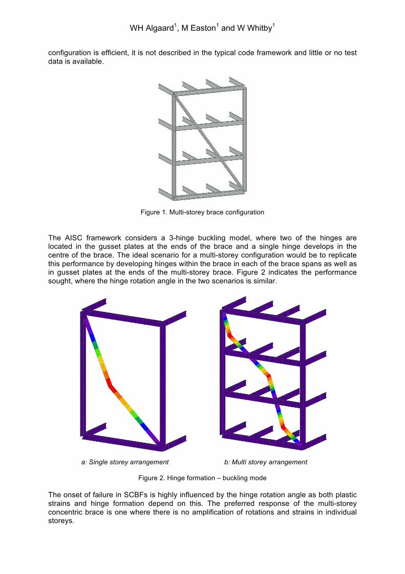
William H. Algaard1, Marc Easton2 and William Whitby3 Abstract Special Concentric Braced Frames (SCBFs) can provide an efficient design solution for tall buildings in zones of moderate to high seismicity. Such a solution provides a direct axial load path and offers the moderate amount of ductility typically sought for tall buildings. The scale of these buildings is such that braces are large enough to provide reasonably symmetrical behaviour in tension and compression. However, on a typical perimeter column grid of 8-12m the brace angle resulting from conventional single storey braces is inefficient. A more efficient solution is achieved with multi-storey braces spanning across 2-3 floors between columns, taking restraint at intermediate floors to preserve global compactness of the braces and reasonably symmetrical behaviour. However, the design code framework (e.g. AISC 341-10) does not extend to such a configuration, and there is little or no test data available. This paper reports on the findings from an analytical case study carried out for the design of Reforma 509, a 238m tall mixed-use tower currently under construction in Mexico City, where 3-storey special concentric braces are employed to optimise the efficiency of the structural performance. The study concludes that a multi-storey brace configuration with intermediate restraints can exhibit distributed yielding and provide a similar amount of ductility to conventional single-storey braces. However, to ensure this behaviour the local compactness criteria should be increased to a higher level than the minimum requirements of AISC 341-10. The study also concludes that such an increase in the criteria is beneficial also for single-storey braces. Introduction It is typically appropriate to use low to moderate levels of ductility in the design of tall buildings in seismic zones to preserve performance under wind loading and service level seismic response. Special Concentric Brace Frames (SCBFs, as specified in AISC 341-10) can be considered a materially efficient and cost effective solution for such buildings as they combine a direct and stiff axial load path with a reasonable capacity for inelastic response. Tall buildings generally employ larger braces than low-rise buildings. Large, stocky braces exhibit a more symmetrical behaviour in tension and compression, giving opportunity for a well-balanced and efficient design. However, for a column grid in a typical range of 8-12m a single-storey brace is angled close to the horizontal, resulting in inefficient design. A chevron configuration can achieve suitable angles, but is less direct and less efficient, requiring provisions to resist vertical out of balance loads between columns. A good combination of direct load path, efficient angles and stocky properties can be achieved by concentric braces acting between columns across multiple storeys, taking lateral restraint at intermediate floors. Figure 1 illustrates such a configuration. While this
1 Associate Director, Arup, London, [email protected] 2 Engineer, Arup, London, [email protected] 3 Associate, Arup, London, [email protected]
WH Algaard1, M Easton1 and W Whitby1
configuration is efficient, it is not described in the typical code framework and little or no test data is available.
Figure 1. Multi-storey brace configuration
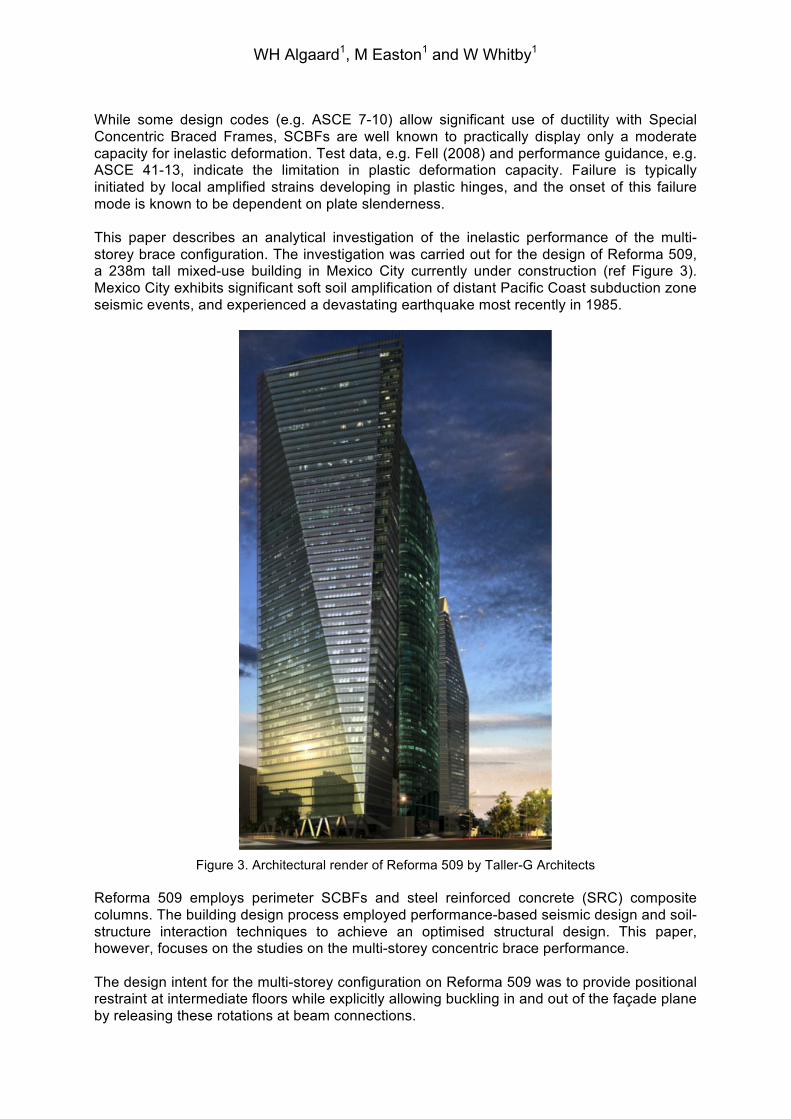
The AISC framework considers a 3-hinge buckling model, where two of the hinges are located in the gusset plates at the ends of the brace and a single hinge develops in the centre of the brace. The ideal scenario for a multi-storey configuration would be to replicate this performance by developing hinges within the brace in each of the brace spans as well as in gusset plates at the ends of the multi-storey brace. Figure 2 indicates the performance sought, where the hinge rotation angle in the two scenarios is similar.
Figure 2. Hinge formation – buckling mode
The onset of failure in SCBFs is highly influenced by the hinge rotation angle as both plastic strains and hinge formation depend on this. The preferred response of the multi-storey concentric brace is one where there is no amplification of rotations and strains in individual storeys.
a: Single storey arrangement b: Multi storey arrangement
WH Algaard1, M Easton1 and W Whitby1
While some design codes (e.g. ASCE 7-10) allow significant use of ductility with Special Concentric Braced Frames, SCBFs are well known to practically display only a moderate capacity for inelastic deformation. Test data, e.g. Fell (2008) and performance guidance, e.g. ASCE 41-13, indicate the limitation in plastic deformation capacity. Failure is typically initiated by local amplified strains developing in plastic hinges, and the onset of this failure mode is known to be dependent on plate slenderness. This paper describes an analytical investigation of the inelastic performance of the multi-storey brace configuration. The investigation was carried out for the design of Reforma 509, a 238m tall mixed-use building in Mexico City currently under construction (ref Figure 3). Mexico City exhibits significant soft soil amplification of distant Pacific Coast subduction zone seismic events, and experienced a devastating earthquake most recently in 1985.
Figure 3. Architectural render of Reforma 509 by Taller-G Architects
Reforma 509 employs perimeter SCBFs and steel reinforced concrete (SRC) composite columns. The building design process employed performance-based seismic design and soil-structure interaction techniques to achieve an optimised structural design. This paper, however, focuses on the studies on the multi-storey concentric brace performance. The design intent for the multi-storey configuration on Reforma 509 was to provide positional restraint at intermediate floors while explicitly allowing buckling in and out of the façade plane by releasing these rotations at beam connections.
Fig. 1: Architectural render of Reforma 509

WH Algaard1, M Easton1 and W Whitby1
Case study The objective of the design study was to develop a multi-storey concentric brace design basis that could be justified through relation to established guidance for single-storey braces. The preferred behaviour is one where each span of the brace participates in accommodating the brace strain, such that there is no amplified strain in any one span. This requires a buckling mode that links the brace spans together, which in turn requires that the brace connections to the restraining floor framing need to allow free rotation around one axis. First principles assessments identify that the brace must maintain flexural continuity across the support, with a minimal rotational restraint provided by the floor beam elements providing positional restraint. With a conventional gusset plate end connection detail the lower buckling mode is in and out of the vertical plane. This requires the floor beam connection spanning towards the façade to be rotationally released. Edge beams may be fixed provided they have low torsional stiffness and are locally disconnected from the floor slab. Elastic eigenvalue buckling analysis of the frame configurations offers limited insight into the expected behaviour. It can easily be shown that the lower elastic buckling mode is one where each span contributes to an overall buckled shape with three alternating half-sine waves. It can also be demonstrated with a virtual work analysis of an idealised system that the formation of one hinge in each brace span exhibits less internal energy than other modes. The inelastic large-strain performance of a multi-storey brace system is however highly nonlinear, and highly dependent on the onset and development of plastic hinges. The diagrams in Figure 4 below indicate deflected shape and bending moment profiles for some scenarios. A key observation is that the initial formation of one hinge alters the bending moment profile from an idealised linear buckling mode, where high moments develop at the restraint point, introducing the risk of concentrated deformation.
Figure 4. Deflected shape and bending moment profiles for idealised condition and following onset of
one hinge. The inelastic performance of multi-storey special concentric brace configurations was investigated using non-linear finite element analysis in LS-Dyna (2014). Single braced bays were modelled, using a highly refined 2D mesh to represent the braces, gusset plates and intermediate connections. A non-linear material model, with yield, strain hardening and failure representation was used for these components. The remaining bays (columns and beams) were represented with 1D elastic elements.
a: Idealised b: Following hinge formation

WH Algaard1, M Easton1 and W Whitby1
The braced bays were subjected to cyclic racking deformation. This was applied in a quasistatic manner, following the standard AISC loading protocols shown in Figure 5 below. This applies increasing amplitudes in tension and compression and reflects the typical cyclic loading applied in experimental studies. The overall behaviour of the bracing configuration was evaluated and comparisons made with published test data for single-storey configurations.
Figure 5. AISC Standard loading protocol The loading protocol in Figure 5 gives the strain history in the brace. This can be correlated with the shear strain across the bracing module by considering the bracing angle and rigid portion between the brace workpoints. A bracing angle of 45° gives an axial brace strain of half the shear strain. The rigid portions can be estimated as the lengths between the gusset plate fold lines and the workpoints, typically resulting in 25%-50% increase in the axial strain over the active brace length compared with the distance between work points. The axial deformation range of consideration for the performance of the braces relates to the drift demands on the project. On Reforma 509 racking drifts of up to 1% were predicted at Maximum Considered Earthquake level response. For the configuration on that project this compares with an axial deformation of around 0.7%, which is similar to the allowable deformation at Life Safety limit for SCBFs to ASCE 41-13. Life safety plastic strain limit = 5Δc, where Δc = pc/E and pc is the axial stress at onset of buckling. Validation of analytical approach The analytical FE approach using LS-Dyna was validated with comparison with experimental tests of single-storey braces. Analytical simulations of specific experimental test arrangements were completed, reflecting the materials, sections, geometry and loading protocol. Direct comparisons were then made of global behaviour, local behaviour and onset of failure. The experimental test set-up and results were taken from Fell (2008). The tests considered were of US HSS 4” by 4” hollow sections with 1/4” and 3/8” wall thickness, around 2.75m long.

WH Algaard1, M Easton1 and W Whitby1
The representation of the global behaviour was evaluated through comparison of the hysteresis loops obtained experimentally and analytically. Figure 6 shows this comparison, demonstrating that buckling, hinge formation, tensile yield and onset of failure correlate well, to provide a good representation of the global behaviour.
Figure 6. Comparison of hysteresis loops from experimental (grey) and analytical simulations (blue) Local behaviour at the hinge region is critical to the performance of the brace as amplified strains in this location ultimately results in overall brace failure. Figure 7 shows hinge formation and Figure 8 shows plastic behaviour and strain amplification in the hinge region. Photos are taken from Fell (2008).
Figure 7. Buckling and amplified strains at local hinge formation in single storey brace
-‐200
-‐100
0
100
200
300
400
-‐3 -‐2 -‐1 0 1 2 3
Chart Title
-‐200
-‐150
-‐100
-‐50
0
50
100
150
200
250
-‐2 -‐1.5 -‐1 -‐0.5 0 0.5 1 1.5 2
WH Algaard1, M Easton1 and W Whitby1
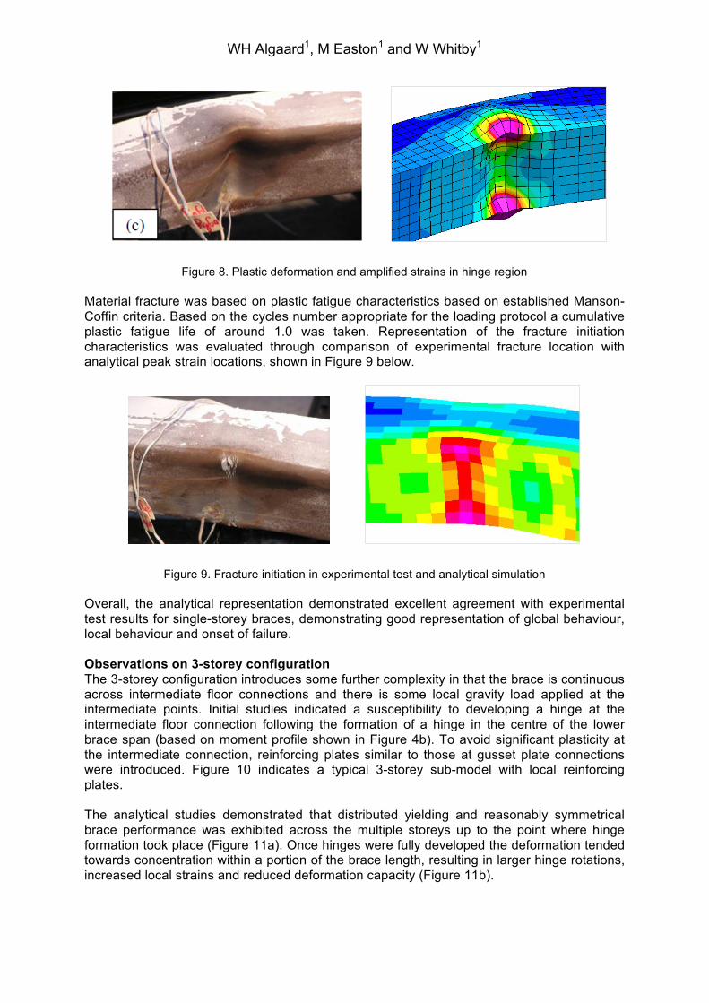
Figure 8. Plastic deformation and amplified strains in hinge region Material fracture was based on plastic fatigue characteristics based on established Manson-Coffin criteria. Based on the cycles number appropriate for the loading protocol a cumulative plastic fatigue life of around 1.0 was taken. Representation of the fracture initiation characteristics was evaluated through comparison of experimental fracture location with analytical peak strain locations, shown in Figure 9 below.
Figure 9. Fracture initiation in experimental test and analytical simulation Overall, the analytical representation demonstrated excellent agreement with experimental test results for single-storey braces, demonstrating good representation of global behaviour, local behaviour and onset of failure. Observations on 3-storey configuration The 3-storey configuration introduces some further complexity in that the brace is continuous across intermediate floor connections and there is some local gravity load applied at the intermediate points. Initial studies indicated a susceptibility to developing a hinge at the intermediate floor connection following the formation of a hinge in the centre of the lower brace span (based on moment profile shown in Figure 4b). To avoid significant plasticity at the intermediate connection, reinforcing plates similar to those at gusset plate connections were introduced. Figure 10 indicates a typical 3-storey sub-model with local reinforcing plates. The analytical studies demonstrated that distributed yielding and reasonably symmetrical brace performance was exhibited across the multiple storeys up to the point where hinge formation took place (Figure 11a). Once hinges were fully developed the deformation tended towards concentration within a portion of the brace length, resulting in larger hinge rotations, increased local strains and reduced deformation capacity (Figure 11b).

WH Algaard1, M Easton1 and W Whitby1
Figure 10. 3-storey configuration
Figure 11a (left) Distributed and reasonably symmetrical plasticity. Figure 8b (right) axial deformation
concentrated in lower 1-2 storeys of 3-storey module. The performance of various brace configurations was assessed quantitatively by evaluating the accumulation of damage during cyclic loading simulations. Six brace configurations were tested analytically; the braces had a range of local and global slenderness values and were configured over 1, 2 or 3 storeys. For each configuration the accumulation of peak strain was monitored during applied displacement cycles according to the AISC loading protocol (ref. Figure 5). The summary of the results is shown in Figure 12 below. Peak strain reports the maximum occurring strain on any surface in any finite element within the brace, while racking drift represents the shear angle the brace is subjected to. The data points are for the last compressive cycle within the loading protocol, i.e. 13.5s and 25.5s in Figure 5. Failure strain is estimated to be around 1, which also correlates with test results for single storey braces. ASCE 41-13 Life Safety deformation capacity equates to around 0.7% axial strain, which in turn equates to approximately 1% racking drift. This is also the peak strain demand at MCE for the braces in Reforma 509, so the data points of principal interest are therefore the ones at 1.0% racking drift in Figure 9.

WH Algaard1, M Easton1 and W Whitby1
Figure 12. Accumulation of peak strain versus cyclic drift
The onset of hinge formation was found to be highly dependent on the local slenderness, i.e. plate width over plate thickness (B/t) ratios. However, it was found to be relatively insensitive to the overall element slenderness (kL/ry), as shown in Figure 13 below.
Figure 13. Maximum peak strain versus local and global slenderness
The results include those for the single-storey 250x20 brace (fabricated box section, 250mm square outside dimensions and 20mm plate thickness) with a B/t ratio of 10.5, which is approaching the maximum permitted in AISC 341-10 of 13.5. The damage accumulation indicates that this brace may not necessarily meet the Life Safety criteria for the 5-6 large cycles included in the loading protocol, representative of long-duration ground shaking in
0
1
2
3
4
5
6
0.0% 0.2% 0.4% 0.6% 0.8% 1.0% 1.2% 1.4% 1.6%
Pea
k S
train
Racking drift
Peak Strain vs. drift
400x40 B/t=8 3-Storey250x20 B/t=10.5 3-Storey300x22.5 B/t=11.3 2-Storey300x30 B/t=8.7 2-Storey200x20 B/t=8.5 2-Storey250x20 B/t=10.5 1-StoreyApprox. failure
0
0.5
1
1.5
2
2.5
3
3.5
0 10 20 30 40 50 60 70 80
Peak strain
Global slenderness
Strain vs Slenderness at 1% racking drift
0
0.5
1
1.5
2
2.5
3
3.5
0 2 4 6 8 10 12
Peak strain
B/t
Strain vs B/t at 1% racking drift
B/t = 11.3
B/t = 10.5
B/t = 10.5
B/t = 8 B/t = 8.7
B/t = 8.5
λ = 70
λ = 56
λ = 56
λ = 36 λ = 72
λ = 72

WH Algaard1, M Easton1 and W Whitby1
Mexico City. Failure of concentric braces with high B/t ratios (but within the AISC limits) to meet deformation requirements have been identified in earlier studies, e.g. Fell (2008). Multi-storey braces with high B/t ratios (3-storey 250x20 and 2-storey 300x22.5) were found to accumulate damage faster than the single-storey brace, due to concentrating damage in selected brace spans and amplifying the hinge rotation angle in these. However, multi-storey braces with low B/t ratios (3-storey 400x40, 2-storey 300x30 and 200x20) accumulate damage significantly slower than the code compliant single-storey brace. This is attributed to the delayed onset of hinge formation, and subsequent reduced strains in kinked regions. The analytical study concurs with observations made in published experimental tests: that reducing the B/t ratios in the braces improves the deformation capability and energy dissipation. The study concludes that multi-storey braces exhibit well distributed plasticity when detailed with B/t ratios of less than 9, connections at intermediate floors released for rotation around the relevant axis and reinforcing plates applied at the intermediate connections. Conclusions and design recommendations By observing uprated compactness criteria compared with limits in AISC 341-10 the onset of hinge formation is delayed to be consistent with Life Safety limits in ASCE 41-13. The study indicated that applying a limit of around 65% of the code limit (or B/t of 9 or less) significantly improved the performance of the square hollow section braces on Reforma 509. The uprating of the compactness criteria maintains distributed yielding and reasonably symmetrical multi-storey behaviour within the computed Maximum Considered Earthquake drifts for the building. The study concludes that appropriate inelastic response of multi-storey Special Concentric Braces can be relied upon for efficient design of tall buildings with low to moderate ductility demands. Recommendations for further research It is recommended that further physical testing is undertaken to confirm the results of the finite element analysis for multi-storey braces shown in this study, though previous testing has validated the computational response of the typical single storey bracing arrangement. It is additionally suggested to investigate further the effects of local slenderness ratios on plastic hinge formation in AISC 341-10 for both single and multi-storey bracing arrangements, with a recommendation that these limits are tightened to ensure adequate ductility before the formation of plastic hinges under cyclic loading.
REFERENCES American Institute of Steel Construction, AISC (2010). American National Standard, ANSI/AISC 341-10 Seismic Provision for Structural Steel Buildings. American Society of Civil Engineers, ASCE (2010). ASCE/SEI 7-10, Minimum Design Load for Buildings and Other Structures. American Society of Civil Engineers, ASCE (2013). ASCE/SEI 41-13, Seismic Rehabilitation of Existing Buildings.
Fell BV (2008) Large-Scale Testing and Simulation of Earthquake-Induced Ultra Low Cycle Fatigue in Bracing Members Subjected to Cyclic Inelastic Buckling Ph.D. Thesis, University of California, USA
LS-DYNA v. mpp971d R7.1.1 (2014), Livermore Software Technology Corporation, USA.