seismic performance of steel friction connections
TRANSCRIPT

1
SEISMIC PERFORMANCE OF STEEL FRICTION CONNECTIONS
CONSIDERING DIRECT-REPAIR COSTS
Yeow TZ, Orumiyehei A, Sullivan TJ, MacRae GA, Clifton GC, and Elwood KJ
ABSTRACT
This study compares seismic losses considering initial construction costs and direct-repair costs for New Zealand
steel moment-resisting frame buildings with friction connections and those with extended bolted-end-plate
connections. A total of 12 buildings have been designed and analysed considering both connection types, two
building heights (4-storey and 12-storey), and three locations around New Zealand (Auckland, Christchurch, and
Wellington). It was found that buildings with friction connections required design to a higher design ductility, yet
are generally stiffer due to larger beams being required to satisfy higher connection overstrength requirements.
This resulted in the frames with friction connections experiencing lower interstorey drifts on most floors but
similar peak total floor accelerations, and subsequently incurring lower drift-related seismic repair losses. Frames
with friction connections tended to have lower expected net-present-costs within 50 years of the building being in
service for shorter buildings and/or if located in regions of high seismicity. None of the frames with friction
connections in Auckland showed any benefits due to the low seismicity of the region.
1.0 INTRODUCTION
The 2010-2011 Canterbury earthquakes caused major damage which led to over 1,240 buildings being demolished
(as of February 2015) in the central business district (Gates 2015). However, a large proportion of steel buildings
had damage that was deemed reparable and were hence reused. This has resulted in a significant uptake of steel
buildings in Christchurch, with over 80% of new total floor area being supported by steel or steel-composite
construction (Bruneau and MacRae 2017; MacRae and Clifton 2015). Furthermore, interviews with engineering
firms by Bruneau and MacRae (2017) indicated that steel is also becoming increasingly more common in other
major urban centres in New Zealand.
In addition to traditional steel frames, other structural systems currently being adopted in Christchurch include (i)
nominally elastic systems, (ii) systems with buckling-restrained-braces, (iii) eccentrically braced frames with
replaceable links, (iv) base isolation, and (v) rocking frame systems (Bruneau and MacRae 2017; MacRae and
Clifton 2015). However, one solution rarely used in the primary lateral load resisting system are friction
connections, which dissipate energy through friction instead of inelastic actions and have superior reparability
compared to more traditional connections. This could be due to (i) ongoing refinement of solutions in research,
(ii) industry’s unfamiliarity in design approaches and application, and (iii) benefits not quantified in a manner
easily understood by stakeholders.
One manner in which the benefits of adopting friction connections, or other low-damage technologies in general,
can be assessed is by performing seismic loss estimation, which quantifies losses in terms of direct damage-repair
costs, operational downtime, and injuries. This approach is currently used by the US Resiliency Council (2015)
to give building ratings based on the likely seismic performance, with better performing buildings receiving higher
ratings. Such an approach may also be useful for implementation in New Zealand practice. However, downtime

2
and injuries are difficult to quantity as they are dependent on location specific variables, such as restricted access
due to cordons.
This paper looks to provide insight into the relative performance and cost-effectiveness (considering difference in
initial construction costs and damage-related losses) of implementing friction beam-column and column-base
joints in steel moment-resisting frames against those with traditional joints. The work considers 4-storey and 12-
storey buildings designed to minimum requirements of New Zealand standards for Auckland, Christchurch, and
Wellington. Through this research, answers to the following questions are sought:
1) How does the design of frames with friction connections differ from more traditional solutions?
2) What is the impact of using friction connections instead of traditional connections on peak inter-storey
drifts and total floor accelerations?
3) What is the impact of using friction connections instead of traditional connections on seismic losses?
4) Are friction connections likely to have lower expected overall costs (including initial construction and
seismic losses) within 50 years of being in service?
2.0 BACKGROUND
2.1 Friction connection mechanics and experimental tests
Friction connections are steel connections which dissipate energy through friction. These may be located at the
beam-column joint (Clifton 2005; Khoo et al. 2012), column bases (Borzouie et al. 2015), eccentrically braced
frame links (Leung et al. 2015), and braces (Golondrino et al. 2015). An example of friction beam-column joints
and column-base joints are shown in Figures 1a and 1b, respectively, where sliding is permitted at the web and
the bottom beam flange for the former and at both column flanges for the latter. Each sliding region has a flange
plate with elongated holes to enable movement, a cap plate, and shims with high hardness in between each surface.
Advancements in the friction connections, such as the use of Beville washers (Ramhormozian et al. 2014), have
been proposed, though research is currently on-going in this regard and hence only the configuration shown in
Figure 1 is considered further.
The idealized joint behaviour without axial loading is shown in Figure 1c (MacRae et al. 2010). Here, the joint
moment resistance increases from zero at rest (point a) until sliding initiates between the flange and flange plate
(point b). Further moments can be resisted until sliding initiates between the cap plate and flange plate (point c),
after which sliding fully occurs on both surfaces. The same occurs if the joint is loaded in the opposite direction
(points d and e). In reality, the transition is smoother as shown by experimental results of the friction beam-column
joint (Khoo et al. 2012) and the friction column base connection (Borzouie et al. 2015) in Figures 1d and 1e,
respectively. Of particular interest is the column-base connection behaviour which exhibits self-centring
characteristics. This is because when one of the surfaces slides when the moment demand is significant enough,
the column base pivots about the opposite surface. As the axial reaction force is concentrated at this pivot point,
the eccentricity between the pivot point and the centroid of the section where the axial demand force acts causes
a restorative moment akin to rocking columns, resulting in the self-centring properties observed in Figure 1e.
Note, however, that the shape of the column base hysteretic behaviour may not always match that shown in Figure
1e as it would depend on the ratio of the restoring moment to the moment corresponding to the friction capacity.

3
Unidirectional quasi-static cycling testing of a beam-column friction connection undertaken by Clifton (2005)
showed that the joint may accommodate a further 10-15 mrad of rotation after the bolts reach the end of the
elongated holes before the bolts are permanently weakened, and can accommodate up to 120 mrad of plastic
rotation in total before the bottom flange plate fractures. It was noted that the top and web plates were still intact
at this point which prevented complete fallout of the beam. The authors are not aware of other tests performed on
the friction connections at beam-column joints or column bases to reach failure.
(a) (b)
(c) (d) (e)
Figure 1. Friction connections examples and details; (a) example of a sliding hinge joint (MacRae et al. 2010), (b) example of a friction base connection (Borzouie et al. 2015), (c) idealized joint behaviour (MacRae et al. 2010), (d) hysteretic behaviour of sliding hinge joint (Khoo et al. 2012), and (e) hysteretic behaviour of
friction base connection (Borzouie et al. 2015)
2.2 Friction connection design
In early designs, the sliding shear capacity between each interface of the friction connection was estimated
following a model developed by Clifton (2005) based on plastic bolt theory which considers bolt axial-moment-
shear interaction, which was further refined by MacRae et al. (2010). However, simpler models based on an
assumed friction coefficient of 0.25 have since been proposed by Khoo et al. (2015) for use in engineering practice
as shown in Eq 1.
bstfnewss nnNV ×××= 25.0,(1)
where Vss,new is the sliding shear capacity, Ntf is the proof load of a single bolt, ns is the number of sliding surfaces
(usually taken as two), and nb is the number of bolts. The flexural capacity of the joint is therefore the shear
capacity of the interface multiplied by the lever arm to the point of rotation considering all sliding surfaces. A
design force reduction factor and an overstrength factor of 0.7 and 1.4, respectively, are recommended (MacRae
and Clifton 2015). Approaches for designing these joints are available in literature (Clifton 2002; MacRae et al.
2010), and generally consists of (i) selecting the number and size of bolts such that the flexural capacity of the
joint is greater than the design demand, then (ii) designing other plates and welds in the joint, as well as beams

4
and columns, to withstand the overstrength action of the friction connection. The joint is also designed to enable
a “plastic” rotation of 37.5 mrad before the bolts reach the end of the elongated holes.
2.3 Friction connection modelling
Hysteretic models of the sliding hinge joint have been proposed by Clifton (2005) and Khoo (2013), and the
general behaviour is depicted in Figure 2.
Figure 2. Proposed hysteretic model for the sliding hinge joint connection (Khoo 2013)
The elastic, post-first yield, and fully inelastic stiffnesses (kSHJ,o, kSHJ,py, and kSHJ,in, respectively) can be calculated
from Eqs. 2 to 6.
Etb
lVn
bfpbfp
bfpoldssbfb
l
,=∆ (2)
b
lySHJ
d2,
∆=θ (3)
ySHJ
ySHJ
oSHJ
Mk
,
,
,
67.0
θ= (4)
03.0
45.15.3
,
,,
ySHJ
oSHJplllupySHJ
Mkrrk ×== (5)
oSHJoSHJspinSHJ kkrk ,,, 007.0== (6)
where ∆l is the estimated elongation of the bottom flange plate once the sliding force has been reached, nbfb is the
number of bottom flange bolts, Vss,old is the sliding shear capacity obtained from plastic bolt theory (Clifton 2005;
MacRae et al. 2010), lbfp is the longitudinal distance from the point of rotation to the centroid of sliding bolts, bbfp
is the width of the bottom flange plate, tbfp is the thickness of the bottom flange plate, E is the Young’s modulus
of steel, and db is the depth of the beam. A complication here is that Vss,old and MSHJ,y are based on the plastic bolt
theory model, and that the moment capacity based on the simplified model following Eq 1 is more akin to MSHJ,0.
Minor modifications to the hysteretic equations are thus required if the simplified model is followed. Also note
that, as there have not been many experiments where the friction connection has been tested to complete failure,
the strength and stiffness degradation characteristics are not well known, and hence models to capture this effect
have not been proposed for friction connections.
Quadrant 1
Quadrant 2
Quadrant 4
Quadrant 3

5
2.4 Seismic loss estimation
One of the most widely used seismic loss estimation approaches is the Pacific Earthquake Engineering Research
(PEER) centre’s framework (Deierlein et al. 2003) shown in Eq. 7.
( ) ( )∫ ∫ ∫= IMdIMEDPdGEDPDMGdDMDVGDV λλ .|.|.| (7)
where IM is the intensity measure (i.e. measure of ground shaking); EDP is the engineering demand parameter
(i.e. building response); DM is the damage measure (i.e. measure of the component damage); DV is the decision
variable (i.e. losses); λ(DV) and λ(IM) are the annual rates of exceeding a given value of DV and IM, respectively;
and DMDVG | , EDPDMG | and IMEDPG | are probabilities of DV, DM, and EDP conditioned to
DM, EDP, and IM, respectively. Loss estimation is performed in four key stages; (i) probabilistic seismic hazard
analyses to derive λ(IM), (ii) structural analyses using ground motions consistent with the seismic hazard to
estimate IMEDPG | , (iii) use of fragility functions to obtain EDPDMG | , and (iv) use of loss
distributions, DMDVG | , to predict losses.
In the first iteration of the PEER framework, two main overall building damage states were considered; collapse
and non-collapse. In recent years, the non-collapse damage state has been separated into (i) repairable, and (ii)
demolition required. Ramirez and Miranda (2012) proposed that the need for demolition can be assessed by
evaluating the residual drift response of the building. There is, however, a challenge in modelling the residual
response of the steel building with friction connections, particularly at the highly non-linear range, as the strength
and stiffness degradation behaviour of these connections are not currently known. An alternate approach as
described in ATC-58 (Applied Technology Council 2012a; Applied Technology Council 2012b) is to apply a
threshold repair cost value, where if the calculated repair cost is greater than this value then repairs are deemed
uneconomical. It was also observed during the 2010-11 Canterbury earthquakes that a significant number of
buildings were demolished due to financial reasons despite there being small residual drifts (Cooper et al. 2012b;
Elwood et al. 2015), and hence the latter approach is likely to govern particularly in regions where a high
proportion of buildings have insurance.
Several computer programs are available to perform steps (iii) and (iv), such as the Seismic Loss Assessment
Tool, SLAT (Bradley 2011b), the Performance Assessment Calculation Tool, PACT (Applied Technology
Council 2012a; Applied Technology Council 2012b), and the Seismic Performance Prediction Program, SP3
(Haselton and Baker 2017); the former two of which are freeware programs. Of these two, PACT has a larger
fragility database and is able to consider the need for demolition either by (i) considering residual drifts (Ramirez
and Miranda 2012), or (ii) setting a replacement cost threshold. However, an advantage of SLAT is that it
computes losses following the Magnitude-orientated Adaptive Quadrature (MAQ) approach (Bradley et al. 2009b)
which is less computationally demanding compared to the Monte Carlo simulation approach used by PACT.
Equations to compute probabilistic seismic losses which SLAT is based on are available in Bradley et al. (2009a).
3.0 METHODOLOGY
3.1 Case study building design

6
The layout of the case study buildings adopted in this study was defined following discussions with industry, and
is shown in Figure 3. The plan dimensions are 40 m by 24 m for the four storey building (see Figure 3a), and 48
m by 32 m for the 12-storey building. All buildings are designed with a perimeter lateral load resisting frame
along each side of the building, and interior gravity beams and columns (see Figure 3b). All buildings have floor
heights of 4.5 m on the ground floor and 3.6 m on all other floors. The bay width for Auckland buildings is taken
as 12.0 m due to the lower seismicity of the region, while Christchurch and Wellington buildings have 8.0 m bay
widths (see Figure 3c).
(a)
(b) (c)Figure 3. Case study buildings; (a) example of 4-storey isometric view, (b) example of plan view, and (c)
frame elevations
The demands on the frames were obtained from New Zealand design actions standard series NZS1170 (Standards
Australia and Standards New Zealand 2002; Standards Australia and Standards New Zealand 2011; Standards
New Zealand 2002; Standards New Zealand 2004), while design of the structural elements followed the New
Zealand steel structures standard NZS3404 (Standards New Zealand 1997). An iteration process was adopted to
obtain the lightest steel frame possible while satisfying minimum standards. This involved guessing the initial
size of the frame, then checking (i) serviceability drift requirements under wind actions, (ii) serviceability drift
requirements under earthquake actions, (iii) ensuring that the 2.5% interstorey drift limit under ultimate limit state
seismic actions is not exceeded, and (iv) satisfying strength requirements under ultimate limit state gravity, wind
and earthquake actions. One further consideration adopted was to only vary the beam section sizes every three
floors as commonly done in practice to make construction easier. The exception to this was for the top three floors
of all buildings where the beam was varied every floor to ensure that the top floor beams did not have a moment
capacity to demand ratio significantly larger than those on lower floors. The frame sizes were modified until all
requirements were met, and the frame size could not be decreased further.
xy
z
z direction seismic frame
x direction seismic frame
4.5 m
3 @3.6 m
3 @ 8.0 m2 @ 12.0 m
4.5 m
11 @ 3.6 m
4 @ 8.0 m2 @ 12.0 m
Auckland4-storey
Christchurch/Wellington4-storey
Auckland12-storey
Christchurch/Wellington12-storey
x direction seismic frame
z direction seismic frame

7
Two connection types are considered in the design; (i) a “traditional connection” which was taken as an extended
bolted-end-plate connection as it is the most common type used in New Zealand, and (ii) friction connections at
the beam-column joint and the column-base. The selected section sizes for all Auckland buildings are governed
by wind serviceability requirements, and were designed with an inelastic spectrum scaling factor, kµ, of 1.5 or less
for ultimate limit state seismic loading.
For the traditional solution in Christchurch and Wellington, the governing factor was the 2.5% drift requirement
under ultimate limit state seismic actions, and the beam is designed to be the weakest link in the strength hierarchy.
The design drifts for these buildings are reasonably uniform along their height due to the design approach adopted.
Reduced beam sections (RBS) are used to limit the demands on the bolted end-plate connections. Based on the
minimum allowed RBS width suggested by Cowie (2010), the largest possible kµ which could be adopted for
design is 3.0 using Grade 300 steel. It should be noted that design drift calculations using the design loading were
increased by 10% to account for possible increase in flexibility following recommendations from Cowie (2010).
The design of frames with friction connections in Christchurch and Wellington was also mostly drift-governed.
However, in this case the connections are the weak link in the strength hierarchy. Furthermore, due to the ratio of
overstrength factor to design force reduction factor being 2.0 (MacRae and Clifton 2015), kµ = 4.0 and Grade 350
steel had to be adopted for the design to be feasible while satisfying capacity design principles. This still resulted
in larger beam sizes, though the use of higher steel grade did lead to less doubler plates being required at the panel
zones which helped offset some cost. One interesting observation made was that both connection solutions had
similar design drifts under ultimate limit state loading despite the difference in kµ, and is due to the 10% increase
in drifts assumed in the traditional frame due to the use of the RBS. Also, while the building with friction
connections was designed to a larger kµ, both frames have similar nominal strengths due to the smaller design
factor of 0.7 being used for friction connections compared to the traditional frame which uses 0.9.
3.2 Structural modelling
Two-dimensional inelastic structural analyses of all frames were performed in Ruaumoko2D (Carr 2004) using
large displacement analysis to account for P-delta effects and assuming Caughey (1960) damping of 3% on all
modes. An example model layout for the building with friction joints is shown in Figure 4. Note that the effect
of accidental torsion was not considered in this model, though it had to be included in design following NZS1170.5
(Standards New Zealand 2004).

8
Figure 4. Modelling approach for frames with friction connections case
Rotational springs representing the friction beam-column joints, friction column-base connections, and panel
zones were added at the locations shown in Figure 4. The friction beam-column behaviour shown in Figure 5a
follows that outlined previously in Eqs. 2 to 6 with modifications to account for the updated bolt model (Khoo et
al. 2015). The elastic rotational stiffness of the column-base connection in Figure 5b was assumed to be
1.67(EI/L)column based on interpretation of Clause 4.8.3.4.1 from NZS3404 (Standards New Zealand 1997) to
account for base flexibility effects, and the overall behaviour was obtained by combining an inelastic bilinear
hysteresis loop with an elastic bilinear curve. Note that as the ratio of the restoring force to that resulting from
friction is less than 1.0, the column-base behaviour does not exhibit perfect self-centering behaviour observed in
Figure 1e. The panel zone behaviour in Figure 5c follows that proposed by Kim and Engelhardt (2002) excluding
kinematic hardening effects. All strengths considered in the analyses are nominal strengths. Note that while the
nominal strengths prior to full in-elastic response for both the traditional frame and those with the friction
connections are similar, the frame with friction connections does have a pre-yield reduction in stiffness as shown
in Figure 2 and Figure 5a.
(a) (b) (c)Figure 5. Example of adopted hysteresis models; (a) beam-column connection (level 1), (b) column-base
connection, and (c) panel zone
The model used for the traditional frames is similar to that shown in Figure 4, with the difference being that the
beam rotational springs are placed at the centroid of the RBS rather than at the end of the beam elements. Inelastic
bilinear hysteresis behaviour is assumed for the beam and column base, with the elastic rotational stiffness of the
latter also being taken as 1.67(EI/L)column. The elastic rotational stiffness of the beam hinge was taken as infinity,
while the moment of inertia of the beam elements was reduced to approximate the reduced stiffness of the RBS.
-0.03 -0.02 -0.01 0 0.01 0.02 0.03
Rotation (rad)
-2000
-1000
0
1000
2000
-0.03 -0.02 -0.01 0 0.01 0.02 0.03
Rotation (rad)
-1500
-1000
-500
0
500
1000
1500
-0.03 -0.02 -0.01 0 0.01 0.02 0.03
Rotation (rad)
-3000
-2000
-1000
0
1000
2000
3000

9
Flexibility of the extended bolted-end-plate connection was included in the panel zone model from Kim and
Engelhardt (2002) by modifying the stiffnesses following the approach from Eurocode 3 (2009).
The fundamental mode periods of the frame models based on the adopted design and modelling approach are
shown in Table 1. It can be seen that buildings with the friction connections have smaller or similar periods
compared to the traditional frame due to the larger beam sizes selected to satisfy connection overstrength
requirements. Note that even though the buildings in Auckland also satisfied all design criteria including allowable
drifts under serviceability wind loading, the fundamental mode period for the buildings in Auckland are
particularly long. Dynamic structural analysis under wind loading was not performed in this study, and hence real
buildings in Auckland may be required to have greater stiffness than those examined here. Nonetheless, the
relative seismic performance of the frame solutions can still be compared here.
Table 1. Building fundamental mode periods
4-storey building 12-storey buildingLocation Traditional
frameFriction
connectionsTraditional
frameFriction
connectionsAuckland 2.7 s 2.6 s 4.6 s 4.6 s
Christchurch 1.4 s 1.3 s 2.9 s 2.6 sWellington 1.6 s 1.5 s 2.9 s 2.6 s
It is important to note that strength and stiffness degradation effects were not included as this behaviour is not
known for friction connections once the bolt reaches the end of the elongated holes. Building collapse and residual
displacements might therefore not be well captured, as while instability due to P-delta effects may still occur,
actual building collapse may occur earlier had degradation been considered. An alternate approach adopted here
is to impose a drift limit which, if exceeded on any floor of the building, is assumed to trigger building collapse.
In FEMA356 (ASCE 2000) Table C1-3, a peak interstorey drift limit of 5% was suggested for the collapse
prevention limit state of traditional steel frame buildings, and is adopted for the drift limit approach. While this
may not be directly applicable for frames with friction connections, it is likely to be conservative as the friction
connections can undergo a plastic rotation of 37.5 mrad before the bolts reach the end of the elongated hole, and
another 10-15 mrad before the bolts are permanently weakened as discussed previously (Clifton 2002). It should
be noted that FEMA356 (ASCE 2000) has since been replaced with ASCE41 (ASCE 2013). However, the latter
only provided a descriptive drift limit rather than a drift value and as such was not considered. While this approach
is less accurate compared to explicitly considering degradation, this is unlikely to affect seismic losses
significantly as past studies (Aslani and Miranda 2005; Bradley et al. 2009a) have shown that the greatest
contribution to expected annual losses arises from low to moderate intensity shaking seismic events where
collapse is rare.
3.3 Seismic Hazard Analysis and Ground Motion Selection
Probabilistic seismic hazard analysis was performed for Auckland (36.85o S, 174.76o E) at a shear-wave velocity
to 30 m depth (Vs30) of 450 m/s, Christchurch (43.53o S, 172.64o E) for Vs30 = 250 m/s, and Wellington (41.29o S,
174.78o E) for Vs30 = 450 m/s on OpenSHA (Field et al. 2003) using New Zealand-specific rupture forecast models
(Stirling et al. 2012) and attenuation relationships (Bradley 2013) for spectral acceleration at 2.0 s. Spectral
acceleration corresponding to this period was chosen as the conditioning intensity measure as 2.0 s is in-between
the fundamental periods of the 4-storey and 12-storey for the Christchurch and Wellington buildings, though it is

10
on the low side for Auckland buildings. The resulting seismic hazard curves are shown in Figure 6, where the
Auckland and Christchurch’s seismic hazards are notably lower than the design hazard in NZS1170.5 (Standards
New Zealand 2004). The low seismicity for the Auckland region is acknowledged in NZS1170.5 (Standards New
Zealand 2004), which imposed a minimum hazard factor Z of 0.13 to reduce the risk of collapse in moderate
earthquake shaking (Mw6.5 rupture located 20 km from the site). For Christchurch, reasons for differences include
(i) the ground motion prediction equation which NZS1170.5 (Standards New Zealand 2004) is based off
overestimating the effect of small-to-moderate earthquakes (Cooper et al. 2012a), and (ii) simplification of the
spectral curve shape in NZS1170.5 (Standards New Zealand 2004) which resulted in an overestimate of up to
50% for subsoil class C conditions (subsoil class D effects not known) (McVerry 2003).
(a) (b) (c)Figure 6. Comparison of probabilistic seismic hazard with NZS1170.5:2004 for (a) Auckland Sa(2.0s)subsoil class C, (b) Christchurch Sa(2.0s) subsoil class D, and (c) Wellington Sa(2.0s) subsoil class C
The generalized conditioning intensity measure approach (Bradley 2010; Bradley 2012a) is adopted for ground
motion selection to ensure that the selected records are probabilistically consistent with the seismic hazard. This
approach ensures that building response-hazard or loss-hazard results are consistent regardless of the selected
conditioning intensity measure (Bradley 2012b). Other intensity measures, ground motion prediction equations,
correlation relationships, and weighting factors adopted in the procedure are shown in Table 2. This process was
performed at nine separate hazard levels ranging from 80% to 0.2% probability of exceedance in 50 years which
are indicated by markers in Figure 6.
Table 2. Adopted intensity measures, ground motion prediction equations and correlation relationships
Intensity measuresGround motion prediction
equationCorrelation Relationship
Weighting factor
Spectral acceleration
0.05 s
Bradley (2013)for active shallow faults and
volcanic regions
Zhao et al. (2006)for subduction zone regions
Baker and Jayaram (2008)for active shallow faults
and volcanic regions
Goda and Atkinson (2009)for subduction zone
regions
0.047 each,0.70
combined
0.1 s0.2 s0.3 s0.5 s
0.75 s1.0 s1.5 s3.0 s4.0 s5.0 s7.5 s
Peak ground acceleration
Bradley (2011a)Peak ground velocitya
Significant duration 5-75%a
Kempton and Stewart (2006)0.1
Significant duration 5-95%a 0.1Cumulative absolute velocitya Campbell and Bozorgnia (2010) 0.1
a intensity measures considered only for Christchurch
10-2
10-1
100
101
Spectral acceleration at 2.0s (g)
10-4
10-3
10-2
10% in 50y
2% in 50y
PSHA
Selected intensities
NZS1170.5:2004
10-2
10-1
100
101
Spectral acceleration at 2.0s (g)
10-4
10-3
10-2
10% in 50y
2% in 50y
10-2
10-1
100
101
Spectral acceleration at 2.0s (g)
10-4
10-3
10-2
10% in 50y
2% in 50y
11
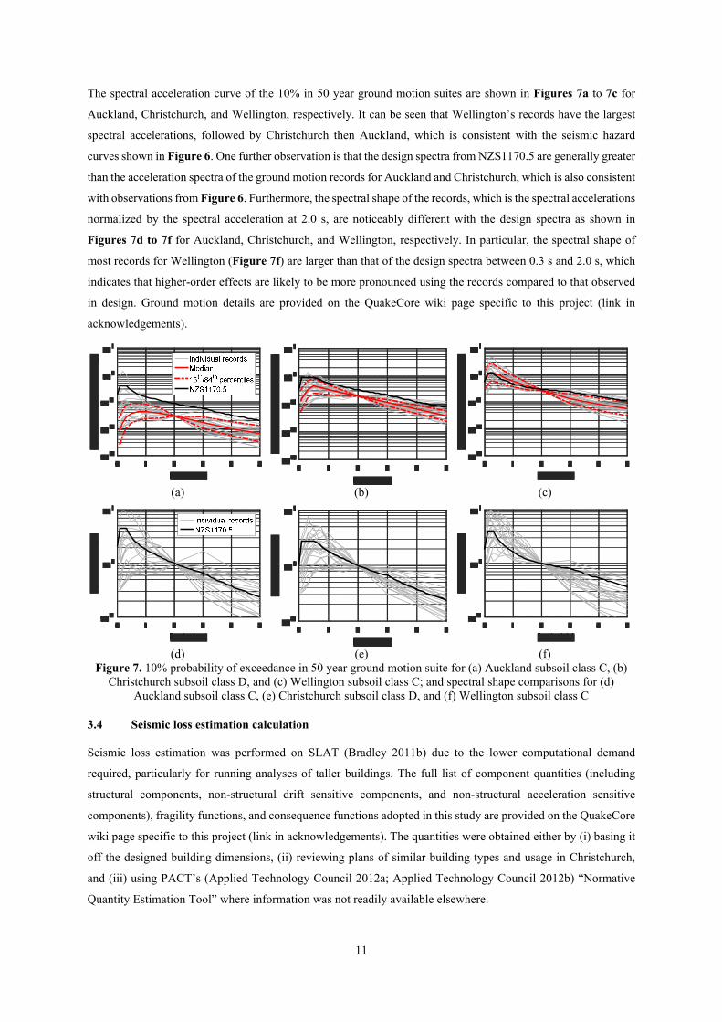
The spectral acceleration curve of the 10% in 50 year ground motion suites are shown in Figures 7a to 7c for
Auckland, Christchurch, and Wellington, respectively. It can be seen that Wellington’s records have the largest
spectral accelerations, followed by Christchurch then Auckland, which is consistent with the seismic hazard
curves shown in Figure 6. One further observation is that the design spectra from NZS1170.5 are generally greater
than the acceleration spectra of the ground motion records for Auckland and Christchurch, which is also consistent
with observations from Figure 6. Furthermore, the spectral shape of the records, which is the spectral accelerations
normalized by the spectral acceleration at 2.0 s, are noticeably different with the design spectra as shown in
Figures 7d to 7f for Auckland, Christchurch, and Wellington, respectively. In particular, the spectral shape of
most records for Wellington (Figure 7f) are larger than that of the design spectra between 0.3 s and 2.0 s, which
indicates that higher-order effects are likely to be more pronounced using the records compared to that observed
in design. Ground motion details are provided on the QuakeCore wiki page specific to this project (link in
acknowledgements).
(a) (b) (c)
(d) (e) (f)Figure 7. 10% probability of exceedance in 50 year ground motion suite for (a) Auckland subsoil class C, (b)
Christchurch subsoil class D, and (c) Wellington subsoil class C; and spectral shape comparisons for (d) Auckland subsoil class C, (e) Christchurch subsoil class D, and (f) Wellington subsoil class C
3.4 Seismic loss estimation calculation
Seismic loss estimation was performed on SLAT (Bradley 2011b) due to the lower computational demand
required, particularly for running analyses of taller buildings. The full list of component quantities (including
structural components, non-structural drift sensitive components, and non-structural acceleration sensitive
components), fragility functions, and consequence functions adopted in this study are provided on the QuakeCore
wiki page specific to this project (link in acknowledgements). The quantities were obtained either by (i) basing it
off the designed building dimensions, (ii) reviewing plans of similar building types and usage in Christchurch,
and (iii) using PACT’s (Applied Technology Council 2012a; Applied Technology Council 2012b) “Normative
Quantity Estimation Tool” where information was not readily available elsewhere.

12
Fragility functions were obtained from literature or from PACT’s (Applied Technology Council 2012a; Applied
Technology Council 2012b) fragility library. The only component for which no fragility functions currently exist
are friction connections. Based on the opinion of the co-authors of this paper who are extensively researching the
behaviour of the friction connections, four main damage states were identified and are described in Table 3.
Description of damage and repair strategies for damage states 1 to 3 are loosely based on observations from
experimental tests by Clifton (2005). An additional “damage” state is introduced to account for post-earthquake
inspections, where non-structural elements may have to be removed to allow for inspection of the connections.
This is assumed to coincide with moderate damage to partitions, for which the fragility function was obtained
from Retamales et al. (2013). This additional damage state was also added to moment-end plate connections for
fair comparisons. As damage state 3 likely occurs only after 5% interstorey drift, where the building would be
deemed to have collapsed before this point, this damage state was not considered further. A dispersion of 0.4 was
assumed for the fragilities for damage states 1 and 2 based on recommendations by Porter et al. (2006), and was
also applied to the loss values due to a lack of information for cost estimates.
Table 3. Friction connection fragility and consequence function
Damage state
Damage Repair Median EDP
Median loss per connection in NZD(1-sided/2-sided)
0 Possible bolt movement
Inspect connections (assume 25% chance of connection being checked)
0.67 5600/7980
1 Loosening of bolts during shaking
Inspect connections, remove, lubricate, and reinsert bolts (assume 50% chance of connection being checked)
1.5 7000/9380
2 Bolts and shims damaged beyond repair
Inspect all connections, remove and replace shims and bolts if required
3.0 7280/9800
3 Bottom flange plate fracture
Remove bolts and shims, flame cut and remove bottom flange plate from column, smoothen surface of column, weld on new flange plate, reassemble shims and bolts.
>5.0 -
The need for demolition was estimated by applying a repair cost to initial construction cost ratio of 0.4. This was
performed during post-processing of the SLAT outputs, as the program was not capable of including this effect
in the assessment at the time of writing. It is assumed that the cost resulting from demolitions is equal to the
building’s full replacement cost.
The building’s value is required to perform net-present-cost (NPC) analyses and to estimate full-replacement costs
(assumed to be 20% greater than the building value). The total value of each building considered in this study is
shown in Table 4. These were estimated using Rawlinson’s (2015) construction handbook, which provided
different cost estimates for different regions within New Zealand. This involved estimating the cost of structural
components, partitions, cladding, and ceilings using quantities outlined in the QuakeCoRE wiki page (link in
acknowledgements), and then adding on per square meter costs for other components as their quantities or
detailing are not as well understood. It is assumed here that the cost of a friction connection itself is similar to that
of a moment-end-plate connection based on discussions with industry which indicated that they are slightly
cheaper to fabricate and cost a similar amount to erect. All non-structural component quantities are assumed to be
consistent regardless of the structural system type, and as such the only difference in costs between the two
building solutions of a given height and for a given location arises from the structural system itself. Interestingly,

13
the cost difference between the two systems for the 12-storey building is over ten times greater compared to the
4-storey building. This is because larger sections are used to support the additional weight of the floors above,
resulting in the total weight of the steel frames increasing disproportionately to the increase in total floor area.
Table 4. Building value ($million NZD)
Frame4-storey 12-storey
Auckland Christchurch Wellington Auckland Christchurch Wellington
Traditional 8.315 8.917 8.222 39.57 42.56 39.43
Friction connections 8.323 8.931 8.231 39.62 42.69 39.53
Methods to calculate NPC are widely available in literature. The expression used by Bradley et al. (2009a) which
is adopted in this paper is shown in Eq 8.
( )EAL
r
eCtrNPC
rt
i
−−+=
1),( (8)
Where Ci can either be taken as the total value or the difference in building value, EAL is the expected annual loss
and is an output from SLAT (Bradley 2011b), r is the discount rate, and t is the duration that the building has been
in service in years. 2% and 6% was considered as r to consider a range of discount rates.
4.0 COMPARISON OF BUILDING RESPONSE
4.1 Building response under 10% in 50 year shaking intensity level
Figure 8 compares the drift response of the buildings when subjected to their respective 10% probability of
exceedance in 50 year ground motion suite. It can be seen that frames with friction connections generally have
lower drifts on most floors, with the difference being more obvious for Wellington where the seismic intensity
was the greatest out of the three regions considered. The first significant reason for this is that the buildings with
friction connections are generally stiffer due to having larger beam section sizes to satisfy friction connection
overstrength demands. A second important factor is that the earlier inelastic behaviour of the frame with friction
connections results in greater energy dissipation earlier on, which also contributes to the reduced drifts at higher
intensity levels. Thirdly, the friction connections do exhibit slight “pinching” behaviour compared to bilinear
hysteresis curves, with less resistance in quadrants 2 and 4 compared to quadrants 1 and 3. This significantly
reduces the likelihood of accumulation of rotation akin to ratcheting effects.
Despite the points made above, the frames with friction connections do generally have greater drifts on the bottom
floor compared to the traditional frames. This is due to the base of the columns also being detailed as a friction
connection, whereas no modifications were made at the base of the frame with moment-end-plates. As such, the
latter is significantly stronger and hence would undergo less column-base rotation.
One important note here is that the drifts were the largest on the upper floors for all buildings. This is because (i)
the second mode effect is more pronounced using the selected ground motion suite compared to that considered
in design following discussions from Figure 7, (ii) the columns are significantly stiffer and stronger than the
beams which result in them behaving like cantilevers when the beams yielded, and (iii) the frames had consistent

14
design interstorey drifts along their height due to the design approach adopted which causes the effects from (i)
and (ii) to be even more prominent.
(a) (b) (c)
(d) (e) (f)Figure 8. Comparison of interstorey drifts using 10% probability of exceedance in 50 year ground motion suite; (a) 4-storey Auckland, (b) 4-storey Christchurch, (c) 4-storey Wellington, (d) 12-storey Auckland, (e) 12-storey
Christchurch, and (f) 12-storey Wellington
Figure 9 shows the peak total floor acceleration response of the buildings under the same ground motion record
suite. It can be seen that the acceleration response between both connection types are similar regardless of location,
with the exception of the 4-storey Wellington buildings where the frame with friction connections had
considerably lower accelerations. One reason could be that while the frames with friction connections yield earlier,
these do have larger beam sections and are thus elastically stiffer, resulting in shorter higher mode periods that
may attract greater spectral accelerations. These two effects may offset each other, leading to a smaller difference
in response compared to the drift comparisons. This could also be due to the similar nominal capacity of these
frames as discussed previously.
0 0.01 0.02 0.03
Interstorey Drift (rad)
0
1
2
3
4
0 0.01 0.02 0.03
Interstorey Drift (rad)
0
1
2
3
4
0 0.01 0.02 0.03
Interstorey Drift (rad)
0
2
4
6
8
10
12
0 0.01 0.02 0.03
Interstorey Drift (rad)
0
2
4
6
8
10
12
0 0.01 0.02 0.03
Interstorey Drift (rad)
0
2
4
6
8
10
12
0 0.01 0.02 0.03
Interstorey Drift (rad)
0
1
2
3
4
Traditional frame
Friction connections
16th and 84th
percentiles
Median

15
(a) (b) (c)
(d) (e) (f)Figure 9. Comparison of peak total floor accelerations using 10% probability of exceedance in 50 year
ground motion suite; (a) 4-storey Auckland, (b) 4-storey Christchurch, (c) 4-storey Wellington, (d) 12-storey Auckland, (e) 12-storey Christchurch, and (f) 12-storey Wellington
Based on these observations, frames with friction connections generally incur lower drifts and similar
accelerations compared to traditional frames if both are designed to the minimum requirements of the New
Zealand standards. Similar observations were made at other shaking intensity levels, and for brevity these results
are not shown here.
4.2 Collapse fragility
As discussed in the methodology, a peak interstorey drift of 5% is assumed to correspond to building collapse.
None of the ground motions in Auckland caused either building to exceed this drift limit. While some cases in
Christchurch do exceed this limit, there are too few to derive a collapse fragility. As such, collapse was not
considered for the Auckland or Christchurch regions.
The collapse fragilities for Wellington buildings were derived by firstly determining the number of records which
exceeded the 5% limit for each hazard level to estimate the probability of collapse at the corresponding shaking
intensity (Figure 10a). A lognormal distribution was then fitted to data points corresponding to shaking intensities
where some, but not all, of the buildings had collapsed (Figure 10b). Visual inspections of Figure 10c show that
the estimated fragility is generally within +/- 5% for seismic intensities where either no collapse had occurred, or
where all buildings had collapsed, which is reasonable. Another approach could be to use the cumulative
distribution of interstorey drifts to estimate the probability of exceeding the 5% drift limit at each hazard level
before fitting the lognormal distribution; however, in cases where lateral instability occurred, the size of the
interstorey drift is extremely large which resulted in a nonsensical distribution of drifts. As such, the approach
adopted here was assumed to be more reasonable.
0 0.5 1 1.5 2
Total floor acceleration (g)
0
1
2
3
4
0 0.5 1 1.5 2
Total floor acceleration (g)
0
1
2
3
4
0 0.5 1 1.5 2
Total floor acceleration (g)
0
2
4
6
8
10
12
0 0.5 1 1.5 2
Total floor acceleration (g)
0
2
4
6
8
10
12
0 0.5 1 1.5 2
Total floor acceleration (g)
0
2
4
6
8
10
12
0 0.5 1 1.5 2
Total floor acceleration (g)
0
1
2
3
4
Traditional frame
Friction connections
16th and 84th
percentiles
Median

16
(a) (b) (c)Figure 10. Computation of collapse fragility; (a) obtaining percentage of analyses exceeding 5% drift limit, (b)
determining best-fit lognormal distribution, and (c) checking lognormal fit
The collapse fragility for the 4-storey and 12-storey Wellington buildings are shown in Figures 11a and 11b,
respectively, where it can be seen that the frame with friction connections have a lower probability of collapse
based on the definitions adopted in this study.
(a) (b)Figure 11. Comparison of collapse fragility for Wellington; (a) 4-storey building, and (b) 12-storey building
4.3 Residual drift comparisons
While residual drifts are not considered in the loss assessments due to lower accuracy from not incorporating
strength and stiffness degradation effects, it is still useful to evaluate this response as an indicator of the potential
need for demolitions. The distribution of the maximum residual drift recorded across the entire building for each
shaking intensity level considering only non-collapse cases are shown in Figure 12. In the Auckland region
(Figures 12a and 12d), the frame with the friction connection tends to have larger residual drifts compared to the
traditional frame. However, the residual drifts for this case are negligible (less than 0.0015 rad) and as such are
not likely to result in demolitions being required. For the other regions where the seismic hazard is greater, the
traditional frame has larger residual drifts compared to the frame with friction connections, which is likely due to
the self-centring characteristics of the column and the “pinching” behaviour of the beam-column friction
connections in the frame with friction connections.
0 0.2 0.4 0.6 0.8 1 1.2 1.4
Spectral acceleration at 2.0s (g)
0
0.05
0.1
0.15
0.2
Analysis data
5% drift limit
-2 -1 0 1 2
ln(spectral acceleration at 2.0 s (g))
-4
-2
0
2
4
Analysis data
Best fit
0 0.2 0.4 0.6 0.8 1 1.2 1.4
Spectral acceleration at 2.0 s (g)
0
0.2
0.4
0.6
0.8
1Analysis data
Best fit
+/- 5% boundary
0 0.2 0.4 0.6 0.8 1 1.2 1.4
Spectral acceleration at 2.0 s (g)
0
0.2
0.4
0.6
0.8
1
2%
in
50
y
10
% i
n 5
0 y

17
(a) (b) (c)
(d) (e) (f)Figure 12. Comparison of residual drifts with shaking intensity level; (a) 4-storey Auckland, (b) 4-storey
Christchurch, (c) 4-storey Wellington, (d) 12-storey Auckland, (e) 12-storey Christchurch, and (f) 12-storey Wellington
FEMA356 (ASCE 2000) recommended a permanent drift value of 1% for steel moment frames to trigger the “life
safety” state where, according to Table C1-2 of the document, the building “may be beyond economical repair”.
Other studies (Iwata et al. 2005; McCormick et al. 2008) have suggested a residual drift value of 0.5% instead,
both from a financial viewpoint to straighten the building, and from human psychological elements if left
unstraightened with occupants possibly incurring headaches and dizziness. Regardless of which drift limit is used,
demolition is unlikely to be required in Auckland and for the 4-storey buildings in Christchurch for events smaller
than a 2% in 50 year shaking event. For the 12-storey Christchurch case in Figure 12e, demolition is likely
required for the traditional frame, especially after the 10% in 50 year and 2% in 50 year hazard level where the
84th percentile residual drift value exceeded 0.5% and 1% residual drift, respectively, while the 84th percentile
curve for the frame with friction connections only crossed 0.5% residual drift at 0.4 g. In the case of Wellington,
while both building solutions may require demolition, a greater proportion of traditional frames had residual drifts
greater than both 0.5% and 1% residual drifts. This indicates that if residual drifts are to be used as a measure of
the need for demolition, the damage-related cost of traditional frames would likely increase more than that of the
frame with friction connections. The consequence of not considering this effect in the loss assessments is discussed
later in the paper.
5.0 COMPARISON OF SEISMIC LOSSES
5.1 Loss-IM relationships
The expected direct-repair costs versus shaking intensity relationships are shown in Figure 13, where the
traditional frames incurred larger losses compared to frames with friction connections in all cases. This
demonstrates that frames with friction connections would have better performance during an earthquake in terms
of repair/replacement cost. One important observation from Figure 13 is that the non-collapse repair cost of the
Resi
dual D
rift
(ra
d)
Resi
dual D
rift
(ra
d)
Resi
dual D
rift
(ra
d)
Resi
dual D
rift
(ra
d)
Resi
dual D
rift
(ra
d)
Resi
dual D
rift
(ra
d)
16th and 84th
percentiles
Median1
0% i
n 50
y
2%
in
50
y

18
buildings rarely exceeded 40% of their initial construction cost. As such, demolition is not a major factor based
on the repair cost-ratio approach.
(a) (b) (c)
(d) (e) (f)Figure 13. Expected repair cost versus intensity measure; (a) 4-storey Auckland, (b) 4-storey Christchruch, (c)
4-storey Wellington, (d) 12-storey Auckland, (e) 12-storey Christchurch, and (f) 12-storey Wellington
To investigate if the loss versus shaking intensity relationships are reasonable, the cost breakdown in terms of
floor level and component types was examined considering the 10% in 50 year ground motion shaking intensity.
The expected drift-related loss profile with floor level is shown in Figure 14, where the frame with friction
connections generally had lower losses on most floors except the ground floor. This is consistent with the drift
profiles shown in Figure 8. Similarly, the expected acceleration-related loss profile with floor level in Figure 15
is consistent with the acceleration profiles in Figure 9. Both of these observations indicate that the computed loss
trends are reasonable.
0 0.1 0.2 0.3 0.4 0.5
Spectral Acceleration at 2.0 s (g)
0
1
2
3
0 0.1 0.2 0.3 0.4 0.5
Spectral Acceleration at 2.0 s (g)
0
2
4
6
10%
in
50 y
2%
in
50
y
0 0.5 1 1.5
Spectral Acceleration at 2.0 s (g)
0
2
4
6
8
10
Collapseincluded
Collapseexcluded
0 0.5 1 1.5
Spectral Acceleration at 2.0 s (g)
0
10
20
30
40
50Collapseincluded
Collapseexcluded

19
(a) (b) (c)
(d) (e) (f)Figure 14. Breakdown of drift-related expected repair cost by floor level for 10% in 50 year ground shaking intensity; (a) 4-storey Auckland, (b) 4-storey Christchruch, (c) 4-storey Wellington, (d) 12-storey Auckland,
(e) 12-storey Christchurch, and (f) 12-storey Wellington
(a) (b) (c)
(d) (e) (f)Figure 15. Breakdown of acceleration-related expected repair cost by floor level for 10% in 50 year ground shaking intensity; (a) 4-storey Auckland, (b) 4-storey Christchruch, (c) 4-storey Wellington, (d) 12-storey
Auckland, (e) 12-storey Christchurch, and (f) 12-storey Wellington
The breakdown of costs by component category is shown in Figure 16, where building components within the
frame with friction connections generally have lower losses overall. The main exception to this is the column base
connections due to the frame with friction connections generally experiencing greater drifts on the ground floor
as observed in Figure 8. For the Wellington buildings, the repair cost of beam connections using the friction
connections was lower by 62% and 37% compared to the traditional frame for the 4-storey and 12-storey
0 150 300 450
Expected repair cost ($1000 NZ)
Level 0-1
Level 1-2
Level 2-3
Level 3-4
Sa(2.0s) = 0.03 g
Traditional frame
Friction connections
0 150 300 450
Expected repair cost ($1000 NZ)
Level 0-1
Level 1-2
Level 2-3
Level 3-4
Sa(2.0s) = 0.19 g
0 150 300 450
Expected repair cost ($1000 NZ)
Level 0-1
Level 1-2
Level 2-3
Level 3-4
Sa(2.0s) = 0.26 g
0 150 300 450
Expected repair cost ($1000 NZ)
Level 0-1Level 1-2Level 2-3Level 3-4Level 4-5Level 5-6Level 6-7Level 7-8Level 8-9
Level 9-10Level 10-11Level 11-12
Sa(2.0s) = 0.03 g
0 150 300 450
Expected repair cost ($1000 NZ)
Level 0-1Level 1-2Level 2-3Level 3-4Level 4-5Level 5-6Level 6-7Level 7-8Level 8-9
Level 9-10Level 10-11Level 11-12
Sa(2.0s) = 0.19 g
0 150 300 450
Expected repair cost ($1000 NZ)
Level 0-1Level 1-2Level 2-3Level 3-4Level 4-5Level 5-6Level 6-7Level 7-8Level 8-9
Level 9-10Level 10-11Level 11-12
Sa(2.0s) = 0.26 g
0 150 300 450
Expected repair cost ($1000 NZ)
Level 0
Level 1
Level 2
Level 3
Level 4
Sa(2.0s) = 0.03 g
Traditional frame
Friction connection
0 150 300 450
Expected repair cost ($1000 NZ)
Level 0
Level 1
Level 2
Level 3
Level 4
Sa(2.0s) = 0.19 g
0 150 300 450
Expected repair cost ($1000 NZ)
Level 0
Level 1
Level 2
Level 3
Level 4
Sa(2.0s) = 0.26 g
0 150 300 450
Expected repair cost ($1000 NZ)
Level 0Level 1Level 2Level 3Level 4Level 5Level 6Level 7Level 8Level 9
Level 10Level 11Level 12
Sa(2.0s) = 0.03 g
0 150 300 450
Expected repair cost ($1000 NZ)
Level 0Level 1Level 2Level 3Level 4Level 5Level 6Level 7Level 8Level 9
Level 10Level 11Level 12
Sa(2.0s) = 0.19 g
0 150 300 450
Expected repair cost ($1000 NZ)
Level 0Level 1Level 2Level 3Level 4Level 5Level 6Level 7Level 8Level 9
Level 10Level 11Level 12
Sa(2.0s) = 0.26 g

20
buildings, respectively. No other component which has losses greater than $50,000 in the traditional frame had a
reduction greater than 25%. This demonstrates that the biggest advantage of using friction connections is to reduce
repair costs to the connections itself.
(a) (b) (c)
(d) (e) (f)Figure 16. Breakdown of expected repair cost by component category for 10% in 50 year ground shaking
intensity; (a) 4-storey Auckland, (b) 4-storey Christchruch, (c) 4-storey Wellington, (d) 12-storey Auckland, (e) 12-storey Christchurch, and (f) 12-storey Wellington
5.2 Expected annual loss
The computed expected annual loss for each building, expressed as both absolute cost and as a percentage of full-
replacement cost, and its dispersion (β) are shown in Table 5. One observation here is that EAL is larger for the
taller buildings in terms of absolute cost, but is smaller in terms of percentage of full-replacement cost (FRC).
Similar observations have also been made in past seismic loss studies (Calvi et al. 2014; Ramirez et al. 2012;
Sullivan 2016). One reason is that the response of the 12-storey building is generally lower than that of the 4-
storey building on most floors as shown in Figures 8 and 9, which is possibly due to a larger drift modification
factor, kdm, being considered for the taller building following NZS1170.5 (Standards New Zealand 2004).
Furthermore, the cost of repair of individual beam components may not have increased significantly despite large
sections being used in the 12-storey building, such as the cost of visual inspections.
Table 5. Annual loss of each building
Location
4-storey building 12-storey buildingTraditoinal frame Friction connections Traditoinal frame Friction connections
EAL (NZD)
EAL (%of FRC)
βEAL
(NZD)EAL (%of FRC)
βEAL
(NZD)EAL (%of FRC)
βEAL
(NZD)EAL (%of FRC)
β
Auckland 706 0.007 3.4 601 0.006 3.4 1,270 0.003 3.5 1,140 0.002 3.4Christchurch 11,400 0.107 3.6 9,030 0.084 3.5 25,800 0.050 3.7 22,100 0.043 3.6Wellington 18,100 0.184 3.9 15,000 0.151 3.9 41,000 0.087 4.1 35,000 0.074 4.1
It is important to acknowledge that significant variation in annual losses exists as shown by the dispersions in
Table 5. As such, the focus on EAL may hide the large uncertainty in the loss assessment process, and
investigations regarding the statistical significance of annual losses should be undertaken in future work. Despite
0 100 200 300 400 500
Expected repair cost ($1000 NZ)
Beam connectionColumn base
PartitionsCladding
StairsCeilings
ElevatorsHVAC
SprinklersOther pipesTransformer Sa(2.0s) = 0.03 g
Traditional frame
Friction connections
0 100 200 300 400 500
Expected repair cost ($1000 NZ)
Beam connectionColumn base
PartitionsCladding
StairsCeilings
ElevatorsHVAC
SprinklersOther pipesTransformer Sa(2.0s) = 0.19 g
0 100 200 300 400 500
Expected repair cost ($1000 NZ)
Beam connectionColumn base
PartitionsCladding
StairsCeilings
ElevatorsHVAC
SprinklersOther pipesTransformer Sa(2.0s) = 0.26 g
0 250 500 750 1000
Expected repair cost ($1000 NZ)
Beam connectionColumn base
PartitionsCladding
StairsCeilings
ElevatorsHVAC
SprinklersOther pipesTransformer Sa(2.0s) = 0.03 g
0 250 500 750 1000
Expected repair cost ($1000 NZ)
Beam connectionColumn base
PartitionsCladding
StairsCeilings
ElevatorsHVAC
SprinklersOther pipesTransformer Sa(2.0s) = 0.19 g
0 250 500 750 1000
Expected repair cost ($1000 NZ)
Beam connectionColumn base
PartitionsCladding
StairsCeilings
ElevatorsHVAC
SprinklersOther pipesTransformer Sa(2.0s) = 0.26 g

21
this, EAL is still a useful measure of relative performance, and identifying the shaking intensities which contribute
the most to EAL can provide some insight regarding efficient strategies to limit losses in future events. Consider
Figure 17 which shows the cumulative contribution of losses at various levels of shaking intensity to EAL, where
it can be seen that 40-80% of contributions to EAL arises from seismic intensities smaller than a 10% in 50 year
probability of exceedance event. This shows that an effective way to reduce EAL could be to improve the
performance of the buildings for events below or equivalent to this shaking intensity, which based on Figure 13,
was not necessarily achieved by the frame with friction connections.
(a) (b) (c)
(d) (e) (f)Figure 17. Intensity measure contribution to expected annual loss; (a) 4-storey Auckland, (b) 4-storey
Christchurch, (c) 4-storey Wellington, (d) 12-storey Auckland, (e) 12-storey Christchurch, and (f) 12-storey Wellington
5.3 Net-present-cost assessment
The net-present-cost assessment provides an indication of the expected cumulative losses with time, in addition
to differences in initial construction cost, converted back to present value. This can be useful to identify if
implementation of friction connections is likely to pay off within a given duration of the building being in service.
Net-present-cost curve comparisons using the difference in building values from Table 4 and the expected annual
loss from Table 5 are shown in Figure 18. Neither of the Auckland cases (Figures 18a and 18d) showed much
economic benefit from using friction connections. This is to be expected as the seismic losses in Auckland are
small due to its low seismicity observed from both PSHA and NZS1170.5 (Standards New Zealand 2004).
For the remaining four cases, frames with friction connections tend to have a shorter time to return on investment
for buildings in Wellington compared to those in Christchurch (comparing Figures 18b to 18c and Figures 18e
to 18f) and/or for shorter buildings (comparing Figures 18b to 18e and Figures 18c and 18f). The former is due
to the seismic hazard being larger in Wellington compared to Christchurch as observed in Figure 6 previously,
which results in larger damage and losses occurring at the same ground shaking probability of exceedance in 50
years as observed in Figure 13, and hence greater EAL as observed in Table 5. The latter is due to the losses not
increasing proportionately to the increase in construction costs as discussed previously.
10%
in
50 y
2%
in
50
y

22
Observing Figure 18 in more detail, it can be seen that the 4-storey frames with friction connections in both
Christchurch and Wellington had lower NPC at the end of 50 years compared to the traditional frames, with the
intercepts occurring around 6 to 7 years and around 3 years for Christchurch and Wellington, respectively. This
demonstrates that there could be significant financial incentive for using friction connections for low-rise
buildings. The 12-storey frame with friction connections in Wellington has an intercept around 16 to 27 years,
which highlights that while the time to return on investment is not as short as for the low-rise buildings, this
building solution is still competitive considering direct-repair costs only. The 12-storey Christchurch frame with
friction connections however is less competitive, and reasons for this are explored later.
(a) (b) (c)
(d) (e) (f)Figure 18. Net present cost assessment; (a) 4-storey Auckland, (b) 4-storey Christchruch, (c) 4-storey
Wellington, (d) 12-storey Auckland, (e) 12-storey Christchurch, and (f) 12-storey Wellington
6.0 DISCUSSION
6.1 Importance of seismic hazard
Generally, frames with friction connections are more economically beneficial in Wellington and Christchurch,
except for the 12-storey building case in Christchurch. One of the reasons why the 12-storey frame with friction
connections was not economically beneficial in Christchurch could be due to the low seismic hazard obtained
from PSHA compared to that used in design following NZS1170.5 (Standards New Zealand 2004). The
inconsistency not only affects the seismic losses, but possibly also the building value as the beam sizes would
have likely been smaller had the seismic hazard obtained from PSHA been used in design instead. To investigate
the effect of seismic hazard, the EAL and NPC were recalculated using the code seismic hazard instead. The code
seismic hazard was approximated by fitting a hyperbolic curve fit, in line with recommendations of Bradley et al.
(2007), to the design horizontal spectra values adjusted for the return period factor, and is shown in Figure 19a.
It can be seen from Figure 19b that NPC analyses suggests that the 12-storey frame with friction connections is
likely to be more economically beneficial than the traditional frame at 13 and 22 years for r = 2% and 6%,
0 10 20 30 40 50
Years in service
0
10
20
30
40
50Traditional frame (r=0.06)
Friction connections (r=0.06)
Traditional frame (r=0.02)
Friction connections (r=0.02)
0 10 20 30 40 50
Years in service
0
20
40
60
80
0 10 20 30 40 50
Years in service
0
100
200
300
400
Intercept at 6 years
Intercept at 7 years
0 10 20 30 40 50
Years in service
0
200
400
600
Intercept at 3 years for both r
0 10 20 30 40 50
Years in service
0
200
400
600
800
1000
Difference of $2,400 Intercept at 16
years
Intercept at 27 years

23
respectively. This is in sharp contrast to observations from Figure 18e where the time to return of investment
exceeds 50 years for both values of r. This demonstrates the significant influence of the seismic hazard in the cost-
benefit assessment.
(a) (b)Figure 19. Effect of seismic hazard on net-present-cost analysis; (a) approximated code seismic hazard for Christchurch subsoil class D Sa(2.0s), and (b) net-present-cost analysis of 12-storey Christchurch building
6.2 Impact of residual drifts
As discussed previously, the lack of a strength and stiffness degradation model for friction connections mean that
the estimation of residual drifts may not be accurate, and as such this was not considered in the loss analyses. This
section investigates the potential impact of excluding residual drifts in the assessment by revaluating the losses
for the 12-storey buildings located in Christchurch considering the hazard curve from Figure 6b.
Assuming that the residual drift output examined in Section 4.3 are reasonable, and that 1% residual drift (obtained
from FEMA356 (ASCE 2000)) triggers the need for demolitions, the probability of requiring demolition for the
12-storey buildings for Christchurch is as shown in Figure 20a. Here, the probability of requiring demolition is
significantly larger for the traditional frame compared to the frame with friction connections.
(a) (b) (c)Figure 20. Potential effect of considering residual drifts in the loss assessment; (a) demolition fragility curve,
(b) expected loss-im results, and (c) net-present-cost assessment
The expected repair cost versus shaking intensity relationships were recomputed using the demolition fragility
curve from Figure 20a, the result of which is as shown in Figure 20b. The expected repair cost of the traditional
frame increased significantly compared to the previously calculated expected repair cost in Figure 13e, while the
repair cost of the frame with friction connections remained relatively similar. The expected annual cost calculated
for the traditional frame and the frame with friction connections were $40,000 and $23,200, respectively. The
10-2 10-1 100
Spectral acceleration at 2.0 s (g)
10-4
10-3
10-2
10-1
Best-fit
NZS1170.5 Ne
t-p
rese
nt-
cost
($
10
00
US
)
Intercept at 14 years
Intercept at 22 years
10%
in
50 y
2%
in
50
y
Demolitionincluded
Demolitionexcluded
Intercept
at 9 years
Intercept at 11 years

24
difference between these values ($16,800) is noticeably greater than that obtained excluding residual drift
considerations ($3,700). This resulted in the time to return on investment ranging from 9 to 11 years as shown in
Figure 20c, compared to over 50 years previously. This shows that the consideration of residual drifts is likely to
make friction connections an even more cost-effective solution.
It should be noted that if 0.5% residual drift is considered instead of 1.0% residual drift, the expected annual cost
of the traditional frame and the frame with friction connections becomes $62,100 and $26,300, respectively. The
resulting range of the time to return on investment for the frame with friction connections reduces to 4 to 5 years,
which is about half the time if 1.0% residual drifts was considered. This highlights that the selection of residual
drifts may be significant in influencing decision-making; though in either case the frame with the friction
connections is still the more cost-effective solution.
6.3 Impact of design and modelling decisions
There are several key design and modelling decisions which could have affected the findings obtained in this
study. One such decision is to compare the performance of the buildings designed to obtain the lightest steel frame
possible which met minimum allowable standards. It is possible that a design which is heavier and has higher
initial construction cost could have a lower NPC overall. For example, if Grade 300 steel was adopted for the
frame with friction connections instead, larger beams would be used which would stiffen the frame, resulting in
lower drifts and probability of collapse but potentially increasing accelerations. Methods to also stiffen the frame,
such as choosing between increasing the beam or column size, could also have an effect. Nonetheless, the
comparisons made in this paper are still useful to provide an indication on the relative performance of these
buildings with time.
Another potentially significant modelling decision is the exclusion of strength and stiffness deterioration effects
in the structural model, and instead imposing a 5% drift limit to approximate collapse effects and ignoring residual
drifts altogether in the loss analyses as discussed previously. As the 5% limit was based on code recommendations,
it is likely to be on the conservative side for both the traditional frame and the frame with friction connections,
which would result in a decrease in expected annual loss and net-present-costs for both connection variants if
strength and stiffness deterioration is considered. However, the frame with the friction connections should have a
greater percentage decrease as it is able to withstand rotations of up to 120 mrad before fracture occurs (Clifton
2002), which is much higher than that which steel beam elements are typically able to achieve. It is not
immediately clear how the difference in expected annual loss between both connection variants and the time to
return on investment for the frame with friction connections would change, but despite this uncertainty the frame
with friction connections would most likely remain a cost-effective solution for most steel moment-resisting
frames in the Christchurch and Wellington region. Nonetheless, experimental work is required to better understand
the strength and stiffness deterioration properties of friction connections so that these could be modelled in the
future. Results from such work would also be beneficial to develop higher quality fragility functions for friction
connections.
6.4 Other considerations
While this study has focused on comparing the performance of steel moment resisting frames with friction
connections against that of frames with more traditional connections considering direct-repair costs and net-

25
present-cost analyses, it is only one of many performance measures. Injuries and downtime are other examples of
losses within the PEER framework which were not considered in this study. As the moment resisting frames with
friction connections generally had lower drifts but similar accelerations compared to their traditional counterparts,
it is likely that corresponding injuries would also be reduced. Furthermore, a key attraction of friction connections
is its ease of reparability which would decrease downtime. The ease of reparability would also likely reduce costs
of repairs at height, especially if repair work consists of mainly re-tightening or replacing bolts rather than
replacing the beam itself. Consideration of these factors, which are outside the scope of this study, would likely
make frames with friction connections a more attractive option compared to considering direct-repair cost on its
own.
7.0 CONCLUSIONS
This study investigated the cost effectiveness of using friction beam-column joint connections over more
traditional variants (e.g. extended bolted-end-plate connections) using seismic loss estimation. In general, it was
found that:
1) Frames with friction connections tended to require larger beam section sizes compared to those with
traditional connections to satisfy connection overstrength requirements following capacity design
principles.
2) Frames with friction connections generally exhibited smaller peak interstorey drifts, similar peak total
floor accelerations, and had a lower probability of collapse compared to frames with more traditional
connection variants.
3) Frames with friction connections incur lower damage direct-repair costs for most components and floor
levels compared to frames with more traditional connection variants. The building component with the
largest reduction in repair/replacement cost was beam connections.
4) Net-present-cost analyses indicated that the time to return on investment is 7 years or less than for the 4-
storey buildings in Christchurch and Wellington. For the 12-storey Wellington scenario, the time to
return on investment is around 27 years or less depending on the discount rate adopted. The duration is
greater than 50 years for the Auckland scenario due to its low seismicity, and for the 12-storey
Christchurch case when residual drifts are not considered in the loss assessment.
8.0 ACKNOWLEDGEMENTS
This project was supported by QuakeCoRE, a New Zealand Tertiary Education Commission-funded Centre. This
is QuakeCoRE publication number 0256.
The authors would also like to acknowledge Brendon Bradley and Karim Tarbali for their guidance on performing
probabilistic seismic hazard analyses and ground motion selection; Shahab Ramhormozian and Robin Xie for
their advice regarding design, modelling, and repair of friction connections; and Stuart Oliver for
recommendations regarding typical building dimensions.
Information on ground motion records and building components (quantity, fragility, and consequence functions)
are available at the following link:

26
https://wiki.canterbury.ac.nz/display/QuakeCore/Project+17137+-
+Usage+of+Seismic+Loss+Assessment+to+Motivate+High+Performance+Building+Solutions.
REFERENCES
Applied Technology Council (2012a) Seismic Performance Assessment of buildings Volume 1 - Methodology. California, US
Applied Technology Council (2012b) Seismic Performance Assessment of buildings Volume 2 - Implementation Guide. California, US
ASCE (2000) Prestandard and Commentary for the Seismic Rehabilitation of Buildings. Federal Emergency Management Agency, Washington, D.C.
ASCE (2013) Seismic evaluation and retrofit of existing buildings (ASCE/SEI 41-13). American Society of Civil Engineers, Reston, VA.
Aslani H, Miranda E (2005) Probabilistic Earthquake Loss Estimation and Loss Disaggregation in Buildings. Department of Civil and Environmental Engineering, Stanford University,
Baker JW, Jayaram N (2008) Correlation of Spectral Acceleration values from NGA ground motion models. Earthquake Spectra 24:299-317
Borzouie J, MacRae GA, Chase GJ, Rodgers GW, Clifton GC (2015) Experimental studies on cyclic performance of column base strong axis-aligned asymmetric friction connections Journal of Structural Engineering 142:04015078
Bradley BA (2010) A Generalized Conditional Intensity Measure Approach and Holistic Ground Motion Selection Earthquake Engineering and Structural Dynamics 39:1324-1342 doi:10.1002/eqe.995
Bradley BA (2011a) Correlation of significant duration with amplitude and cumulative intensity measures and its use in ground motion selection Journal of Earthquake Engineering 15:809-832
Bradley BA (2011b) SLAT:Seismic Loss Assessment Tool (Version 1.16). Department of Civil and Natural Resources Engineering, University of Canterbury,
Bradley BA (2012a) A Ground Motion Selection Algorithm Based on the Generalized Conditional Intensity Measure Approach Soil Dynamics and Earthquake Engineering 40:48-61 doi:10.1016/j.soildyn.2012.04.007
Bradley BA (2012b) The Seismic Demand Hazard and Importance of the Conditioning Intensity Measure Earthquake Engineering and Structural Dynamics 41:1417-1437 doi:10.1002/eqe.2221
Bradley BA (2013) A New Zealand-Specific Pseudospectral Acceleration Ground-Motion Prediction Equation for Active Shallow Crustal Earthquakes Based on Foreign Models Bulletin of the Seismological Society of America 103:1801-1822 doi:10.1785/0120120021
Bradley BA, Dhakal RP, Cubrinovski M, MacRae GA, Lee DS (2009a) Seismic Loss Estimation for Efficient Decision Making Bulletin of the New Zealand Society of Earthquake Engineering 42:96-110
Bradley BA, Dhakal RP, Cubrinovski M, Mander JB, MacRae GA (2007) Improved seismic hazard model with application to probabilsitic seismic demand analysis Earthquake Engineering and Structural Dynamics 36:2211-2225
Bradley BA, Lee DS, Broughton R, Price C (2009b) Efficient Evaluation of Performance-based Earthquake Engineering Equations Structural Safety 31:65-74 doi:10.1016/j.strusafe.2008.03.003
Bruneau M, MacRae GA (2017) Reconstructing Christchurch: a seismic shift in building structural systems. The Quake Centre, University of Canterbury
Calvi GM, Sullivan TJ, Welch RP A seismic performance classification framework to provide increased seismic resilience. In: 2nd European conference on earthquake engineering and seismology, Istanbul, 25 August - 29 August 2014 2014.
Campbell KW, Bozorgnia Y (2010) A Ground Motion Prediction Equation for the Horizontal Component of Cumulative Absolute Velocity (CAV) Based on the PEER-NGA Strong Motion Database Earthquake Spectra 26:635-650 doi:10.1193/1.3457158

27
Carr AJ (2004) Ruaumoko 2D - Inelastic dynamic analysis program. Department of Civil and Natural Resources Engineering, University of Canterbury, Christchurch
Caughey TK (1960) Calssical Normal Modes in Damped Linear Systems Journal of Applied Mechanics 27:269-271
CEN (Comite´ Europe´en de Normalisation) (2009) Eurocde 3: design of steel structures - Part 1-8: Design of joints. Comite´ Europe´en de Normalisation, Brussels, Belgium
Clifton CG (2002) The Sliding Hinge Joint Design and Construction Bulletin 68:Heavy Engineering Research Association, Auckland, New Zealand
Clifton GC (2005) Semi-rigid joints for moment-resisting steel framed seismic-resisting systems. The University of Auckland, Auckland, New Zealand
Cooper M, Carter R, Fenwick R (2012a) Canterbury Earthquake Royal Commission Final Report Volume 1 -Summary and recommendations in volumes 1-3, seismicity, soils and the design design of buildings. Canterbury Earthquake Royal Commission, Wellington
Cooper M, Carter R, Fenwick R (2012b) Volume 2 - The Performance of Christchurch CBD Buildings. Canterbury Earthquake Royal Commission,
Cowie K (2010) Design example of moment resisting seismic frames with reduced beam sections. Steel Construction of New Zealand
Deierlein GG, Krawinkler H, Cornell CA A Framework for Performance-based Earthquake Engineering. In: 2003 Pacific Conference on Earthquake Engineering, Christchurch, New Zealand, 2003.
Elwood KJ, Marquis F, Kim JH Post-earthquake assessment and repairability of RC buildings: lessons from Canterbury and emerging challenges. In: Tenth Pacific Conference on Earthquake Engineering, Sydney, Australia, 2015.
Field EH, Jordan TH, Cornell CA (2003) OpenSHA: A Developing Community-Modeling Environment for Seismic Hazard Analysis Seismological Research Letters 74:406-419
Gates C (2015) 1240 central Christchurch buildings demolished video. Fairfax New Zealand Limited, The Press
Goda K, Atkinson GM (2009) Probabilistic characterization of spatially correlated response spectra for earthquakes in Japan Bulletin of Seismological Societyof America 99:3003-3020
Golondrino JC, Xie R, MacRae GA, Chase GJ, Rodgers GW, Clifton GC Low damage brace using a symmetrical friction connection detail. In: 2015 New Zealand Socierty for Earthquake Engineering Conference, Rotorua, 2015.
Haselton CB, Baker JW (2017) Seismic performance prediction program, 2.6 edn., Haselton Baker Risk Group, Chico
Iwata Y, Sugimoto H, Kuwamura H (2005) Reparability Limit of Steel Structural Buildings: Study on performance-based design of steel structural buildings Part2. Journal of Structural and Construction Engineering:165-172. (in Japanese)
Kempton JJ, Stewart JP (2006) Prediction equations for significant duration of earthquake ground motions considering site and near-source effects Earthquake Spectra 22:985-1013
Khoo H-H, Clifton C, MacRae G, Zhou H, Ramhormozian S (2015) Proposed design models for the asymmetric friction connection Earthquake Engineering & Structural Dynamics 44:1309-1324 doi:10.1002/eqe.2520
Khoo H-H, Clifton GC, Butterworth J, MacRae GA, Gledhill S, Sidwell G (2012) Development of the self-centering sliding hinge joint with friction ring springs Journal of Constructional Steel Research 78:201-211
Khoo HH (2013) Development of the low damage self-centering sliding hinge joint. University of Auckland, Auckland, New Zealand
Kim KD, Engelhardt MD (2002) Monotonic and cyclic loading models for panel zones in steel moment frames Journal of Constructional Steel Research 58:605-635
Leung HK, Clifton GC, Khoo HH, MacRae GA Experimental studies of eccentrically braced frame with rotational bolted active links. In: 8th International Conference on Behavior of Steel Structures in Seismic Areas, Shanghai, China, 2015.

28
MacRae G, Clifton C Research on sesimic performance of steel structures. In: Steel Innovations 2015, Auckland, New Zealand, 2015.
MacRae GA, Clifton CG, Mackinven H, Mago n, Butterworth J, Pampanin S (2010) The sliding hinge joint moment connection Bulletin of the New Zealand Society for Earthquake Engineering 43:202-212
McCormick J, Aburano H, Ikenaga M, Nakashima M Permissible residual deformation levels for building structures considering both safety and human elements. In: The 14th World Conference on Earthquake Engineering, Beijing, China, 2008.
McVerry GH From hazard maps to code spectra for New Zealand. In: 2003 Pacific Conference on Earthquake Engineering, Christchurch, NZ, 2003.
Porter KA, Kennedy RP, Bachman R (2006) Creating fragility functions for performance-based earthquake engineering Earthquake Spectra 23:471-489
Ramhormozian S, Clifton GC, MacRae GA The asymmetric friction connection with belleville springs in the sliding hinge joint. In: 2014 New Zealand Society for Earthquake Engineering Conference, Auckland, 2014.
Ramirez CM et al. (2012) Expected earthquake damage and repair costs in reinforced concrete frame buildings Earthquake Engineering and Structural Dynamics 41 doi:10.1002/eqe.2216
Ramirez CM, Miranda E (2012) Significance of Residual Drifts in Building Earthquake Loss Estimation Earthquake Engineering and Structural Dynamics 41:1477-1493 doi:10.1002/eqe.2217
Rawlinson & Co (2015) Rawlinsons New Zealand construction handbook. Rawlhouse Publishing, Wellington, New Zealand
Retamales R, Davies R, Mosqueda G, Filiatrault A (2013) Experimental seismic fragility of cold-formed steel framed gypsum partition walls Journal of Structural Engineering 139:1285-1293
Standards Australia, Standards New Zealand (2002) NZS 1170.1:2002. Standards New Zealand, Wellington, New Zealand,
Standards Australia, Standards New Zealand (2011) AS/NZS 1170.2:2002. Standards New Zealand, Wellington, New Zealand
Standards New Zealand (1997) NZS 3404:1997. Standards New Zealand, Wellington, New Zealand,
Standards New Zealand (2002) NZS 1170.0:2002. Standards New Zealand, Wellington, New Zealand,
Standards New Zealand (2004) NZS 1170.5:2004. Standards New Zealand, Wellington, New Zealand,
Stirling MW et al. (2012) National seismic hazard model for New Zealand : 2010 update Bulletin of the Seismological Society of America 102:1514-1542 doi:10.1785/0120110170
Sullivan TJ (2016) Use of limit state loss versus intensity models for simplified estimation of expected annual loss Journal of Earthquake Engineering 20:954-974
US Resiliency Council (2015) USRC building rating system for earthquake hazards - implementation manual. USRC Technical Advisory Committee,
Zhao JX et al. (2006) Attenuation relations of strong ground motion in Japan using site classification based on predominant period Bulletin of the Seismological Society of America 96:898-913