seismic provisions for structural steel buildings · aisc 341-16 seismic provisions for structural...
TRANSCRIPT

AISC 341-16
Seismic Provisions for
Structural Steel Buildings
PUBLIC REVIEW DRAFT dated March 16, 2015
AMERICAN INSTITUTE OF STEEL CONSTRUCTION One East Wacker Drive, Suite 700
Chicago, Illinois 60601-1802

PUBLIC R
EVIEW
ONE D
RAFT
SYMBOLS-i
2016 Seismic Provisions for Structural Steel Buildings PUBLIC REVIEW Draft Dated March 16, 2015
AMERICAN INSTITUTE OF STEEL CONSTRUCTION
1
SYMBOLS 2 3
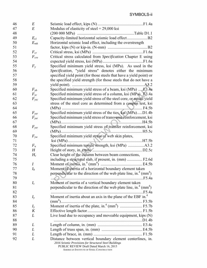
The symbols listed below are to be used in addition to or replacements for 4 those in the AISC Specification for Structural Steel Buildings. Where there 5 is a duplication of the use of a symbol between the Provisions and the AISC 6 Specification for Structural Steel Buildings, the symbol listed herein takes 7 precedence. The section or table number in the right-hand column refers to 8 where the symbol is first used. 9
10 Symbol Definition Reference 11 12 Ab Cross-sectional area of a horizontal 13 boundary element, in.2 (mm2) .......................................... F5.5b 14 Ac Cross-sectional area of a vertical boundary 15 element, in.2 (mm2) ........................................................... F5.5b 16 Acw Area of concrete between web plates, in.2 (mm2) ............ H7.5b 17 Af Gross area of flange, in.2 (mm2) ...................................... E4.4b 18 Ag Gross area, in.2 (mm2) ................................................... . E3.4a 19
Alw Web area of link (excluding flanges), in.2 (mm2) 20 .......................................................................................... F3.5b 21
As Cross-sectional area of the structural steel core, 22 in.2 (mm2) ........................................................................ D1.4b 23 Asc Cross-sectional area of the yielding segment of steel core, in.2 24
(mm2) ................................................................................ F4.5b 25 Ash Minimum area of tie reinforcement, in.2 (mm2) .............. D1.4b 26 Asp Horizontal area of stiffened steel plate in composite plate shear 27
wall, in.2 (mm2) ............................................................... H6.3b 28 Asr Area of transverse reinforcement in coupling beam, 29
in.2 (mm2) ........................................................................ H4.5b 30 Asr Area of longitudinal wall reinforcement provided over the 31
embedment length, Le, in.2 (mm2) ................................... H5.5c 32 Ast Horizontal cross-sectional area of the link stiffener, 33 in.2 (mm2) ........................................................................ F3.5b 34 Asw Area of steel web plates, in.2 (mm2) ................................. H7.5b 35 Atb Area of transfer reinforcement required in each of the first and 36
second regions attached to each of the top and bottom flanges, 37 in.2 (mm2) ........................................................................ H5.5c 38
Aw Area of steel beam web, in.2 (mm2).................................. H4.5b 39 Ca Ratio of required strength to available strength ......Table D1.1 40 Cd Coefficient relating relative brace stiffness and curvature D1.2a 41 D Dead load due to the weight of the structural elements 42 and permanent features on the building, kips (N) ............ D1.4b 43 D Outside diameter of round HSS, in. (mm) ...............Table D1.1 44 D Diameter of the holes, in. (mm) .......................................F5.7a 45
PUBLIC R
EVIEW
ONE D
RAFT
SYMBOLS-ii
2016 Seismic Provisions for Structural Steel Buildings PUBLIC REVIEW Draft Dated March 16, 2015
AMERICAN INSTITUTE OF STEEL CONSTRUCTION
E Seismic load effect, kips (N) .............................................F1.4a 46 E Modulus of elasticity of steel = 29,000 ksi 47
(200 000 MPa) ........................................................Table D1.1 48 Ecl Capacity-limited horizontal seismic load effect .................... B2 49 Emh Horizontal seismic load effect, including the overstrength 50
factor, kips (N) or kip-in. (N-mm) ....................................... B2 51 Fcr Critical stress, ksi (MPa) ..................................................F1.6a 52 Fcre Critical stress calculated from Specification Chapter E using 53
expected yield stress, ksi (MPa) ........................................F1.6a 54 Fy Specified minimum yield stress, ksi (MPa). As used in the 55
Specification, "yield stress" denotes either the minimum 56 specified yield point (for those steels that have a yield point) or 57 the specified yield strength (for those steels that do not have a 58 yield point). ....................................................................... A3.2 59
Fyb Specified minimum yield stress of a beam, ksi (MPa) .... E3.4a 60 Fyc Specified minimum yield stress of a column, ksi (MPa) E3.4a 61 Fysc Specified minimum yield stress of the steel core, or actual yield 62
stress of the steel core as determined from a coupon test, ksi 63 (MPa) ............................................................................... F4.5b 64
Fysr Specified minimum yield stress of the ties, ksi (MPa) ..... D1.4b 65 Fysr Specified minimum yield stress of transverse reinforcement, ksi 66
(MPa) ................................................................................ H4.5b 67 Fysr Specified minimum yield stress of transfer reinforcement, ksi 68
(MPa) ................................................................................ H5.5c 69 Fyw Specified minimum yield stress of web skin plates, 70 ksi (MPa) ......................................................................... H7.5b 71 Fu Specified minimum tensile strength, ksi (MPa) ................ A3.2 72 H Height of story, in. (mm) ................................................. D2.5c 73 Hc Clear height of the column between beam connections, 74
including a structural slab, if present, in. (mm) ............... F2.6d 75 I Moment of inertia, in.4 (mm4) ......................................... E4.5b 76 Ib Moment of inertia of a horizontal boundary element taken 77
perpendicular to the direction of the web plate line, in.4 (mm4) 78 ........................................................................................... F5.4a 79
Ic Moment of inertia of a vertical boundary element taken 80 perpendicular to the direction of the web plate line, in.4 (mm4) 81
...........................................................................................F5.4a 82 Iy Moment of inertia about an axis in the plane of the EBF in.4 83
(mm4) ................................................................................ F3.5b 84 Iy Moment of inertia of the plate, in.4 (mm4) ...................... F5.7b 85 K Effective length factor ...................................................... F1.5b 86 L Live load due to occupancy and moveable equipment, kips (N)87
....................................................................................... D1.4b 88 L Length of column, in. (mm) ............................................ E3.4c 89 L Length of truss span, in. (mm) ........................................ E4.5b 90 L Length of brace, in. (mm) ................................................ F1.5b 91 L Distance between vertical boundary element centerlines, in. 92

PUBLIC R
EVIEW
ONE D
RAFT
SYMBOLS-iii
2016 Seismic Provisions for Structural Steel Buildings PUBLIC REVIEW Draft Dated March 16, 2015
AMERICAN INSTITUTE OF STEEL CONSTRUCTION
(mm) ..................................................................................F5.4a 93 Lb Length between points which are either braced against lateral 94
displacement of compression flange or braced against twist of 95 the cross section, in. (mm)................................................ D1.2a 96
Lcf Clear length of beam, in. (mm) ........................................ E1.6b 97 Lcf Clear distance between column flanges, in. (mm) ........... F5.5b 98 Le Embedment length of coupling beam, in. (mm) ............... H4.5b 99 Lh Distance between plastic hinge locations, as defined within the 100
test report or ANSI/AISC 358, in. (mm) .......................... E2.6d 101 Ls Length of the special segment, in. (mm) ......................... E4.5b 102 Ma Required flexural strength, using ASD load combinations, kip-103
in. (N-mm) ....................................................................... D1.2c 104 Mnc Nominal flexural strength of the chord member of the special 105
segment, kip-in. (N-mm) ................................................. E4.5b 106 Mn,PR Nominal flexural strength of PR connection at a rotation of 0.02 107
rad, kip-in. (N-mm) ......................................................... E1.6c 108 Mp Plastic flexural strength, kip-in. (N-mm) ........................ E1.6b 109 Mp Plastic flexural strength of a link, kip-in. (N-mm) ............F3.4a 110 Mp Plastic flexural strength of the steel, concrete-encased or 111
composite beam, kip-in. (N-mm) .................................... G2.6b 112 Mp Moment corresponding to plastic stress distribution over the 113
composite cross section, kip-in. (N-mm) ......................... G4.6c 114 Mpc Plastic flexural strength of the column, kip-in. (N-mm) . D2.5c 115 Mpcc Plastic flexural strength of a composite column, kip-in. (N-mm) 116
....................................................................................... G2.6f 117 Mp,exp Expected flexural strength, kip-in. (N-mm) .................... D1.2c 118 Mpr Probable maximum moment at the location of the plastic hinge, 119
as determined in accordance with ANSI/AISC 358, or as 120 otherwise determined in a connection prequalification in 121 accordance with Section K1, or in a program of qualification 122 testing in accordance with Section K2, kip-in. (N-mm) .. E3.4a 123
Mr Required flexural strength, kip-in. (N-mm) ..................... D1.2a 124 Mu Required flexural strength, using LRFD load combinations, kip-125
in. (N-mm) ....................................................................... D1.2c 126 Mv Additional moment due to shear amplification from the location 127
of the plastic hinge to the column centerline, kip-in. (N-mm) ..128 ....................................................................................... E3.4a 129
Muv Moment due to shear amplification from the location of the 130 plastic hinge to the column centerline, kip-in. (N-mm) .. G3.4a 131
M*pb Moment at the intersection of the beam and column centerlines 132 determined by projecting the beam maximum developed 133 moments from the column face, kip-in. (N-mm) ............. E3.4a 134
M*pc The flexural strengths of the columns above and below the joint, 135 reduced for axial loads, projected to the beam centerline, kip-in. 136 (N-mm) ............................................................................ E3.4a 137

PUBLIC R
EVIEW
ONE D
RAFT
SYMBOLS-iv
2016 Seismic Provisions for Structural Steel Buildings PUBLIC REVIEW Draft Dated March 16, 2015
AMERICAN INSTITUTE OF STEEL CONSTRUCTION
M*pcc Moment in the column above or below the joint at the 138 intersection of the beam and column centerlines, kip-in. (N-mm) 139 ..................................................................................... ….G3.4a 140
M*p,exp Moment in the steel beam or concrete-encased composite beam 141 at the intersection of the beam and column centerlines, kip-in. 142 (N-mm) ............................................................................ G3.4a 143
NMV Notional load factor for design of multi-tiered buckling- 144 restrained braced frames to account for material variability ......145 .............................................................................F4.4c 146
Nr Number of horizontal rows of perforations .......................F5.7a 147 Pa Required axial strength using ASD load combinations, kips (N)148
Table D1.1 149 Pac Required compressive strength using ASD load combinations, 150
kips (N) ............................................................................ E3.4a 151 Pb Axial design strength of wall at balanced condition, kips (N) 152 ......................................................................................... H5.4 153 Pc Available axial strength, kips (N) .................................... E3.4a 154 Pn Nominal axial compressive strength, kips (N) ................ E4.5a 155 Pnc Nominal axial compressive strength of the chord member at the 156
ends, kips (N) .................................................................. E4.4c 157 Pnt Nominal axial tensile strength of diagonal members of the 158
special segment, kips (N) ................................................ E4.5b 159 Pr Required axial compressive strength, kips (N) ............... E4.4d 160 Pu Required axial strength using LRFD load combinations, kips (N) 161
.................................................................................Table D1.1 162 Puc Required compressive strength using LRFD load combinations, 163
kips (N) ............................................................................ E3.4a 164 Py Axial yield strength, , kips (N) ................................Table D1.1 165 Pysc Axial yield strength of steel core, kips (N) ......................F4.2a 166 Pysc-max Maximum specified axial yield strength of steel core, ksi 167
(MPa) ................................................................................F4.4c 168 Pysc-min Minimum specified axial yield strength of steel core, ksi 169
(MPa) ................................................................................F4.4c 170 R Seismic response modification coefficient ........................... A1 171 R Radius of the cut-out, in. (mm) ....................................... F5.7b 172 Rc Factor to account for expected strength of concrete = 1.5.. H5.5d 173 Rn Nominal strength, kips (N) ................................................ A3.2 174 Rt Ratio of the expected tensile strength to the specified minimum 175
tensile strength Fu ............................................................... A3.2 176 Ry Ratio of the expected yield stress to the specified minimum yield 177
stress, Fy ........................................................................... A3.2 178 Ryb Ratio of the expected yield stress of the beam material to the 179
specified minimum yield stress ........................................ E3.6f 180 Ryc Ratio of the expected yield stress of the column material to the 181
specified minimum yield stress ........................................ E3.6f 182 Ryr Ratio of the expected yield stress of the transverse 183
reinforcement material to the specified minimum yield 184

PUBLIC R
EVIEW
ONE D
RAFT
SYMBOLS-v
2016 Seismic Provisions for Structural Steel Buildings PUBLIC REVIEW Draft Dated March 16, 2015
AMERICAN INSTITUTE OF STEEL CONSTRUCTION
stress ................................................................................. H5.5d 185 Sdiag Shortest center-to-center distance between holes, in. (mm) ...... 186 ........................................................................................F5.7a 187 Va Required shear strength using ASD load combinations, kips (N) 188 ....................................................................................... E1.6b 189 Vcomp Limiting expected shear strength of an encased composite 190
coupling beam, kips (N) .................................................. H4.5b 191 Vn Nominal shear strength of link, kips (N) ........................... F3.3 192 Vn Expected shear strength of a steel coupling beam, kips (N) ...... 193 .......................................................................................... H4.5b 194 Vn,comp Expected shear strength of an encased composite coupling beam, 195
kips (N) ............................................................................. H4.5b 196 Vne Expected vertical shear strength of the special segment, kips (N) 197
....................................................................................... E4.5b 198 Vp Plastic shear strength of a link, kips (N) ..........................F3.4a 199 Vr Required shear strength using LRFD or ASD load combinations, 200
kips (N) ............................................................................ F3.5b 201 Vu Required shear strength using LRFD load combinations, kips (N) 202 ....................................................................................... E1.6b 203 Vy Nominal shear yield strength, kips (N) ........................... F3.5b 204 Ycon Distance from the top of the steel beam to the top of concrete 205
slab or encasement, in. (mm) ........................................... G3.5a 206 YPNA Maximum distance from the maximum concrete compression 207
fiber to the plastic neutral axis, in. (mm) ......................... G3.5a 208 Z Plastic section modulus about the axis of bending, in.3 (mm3) 209
D1.2a 210 Zc Plastic section modulus of the column about the axis of bending, 211
in.3 (mm3) ........................................................................ E3.4a 212 Zx Plastic section modulus about x-axis, in.3 (mm3) ............. E2.6g 213 ZRBS Minimum plastic section modulus at the reduced beam section, 214
in.3 (mm3) ........................................................................ E3.4a 215 a Distance between connectors, in. (mm) ........................... F2.5b 216 b Width of compression element as defined in Specification 217
Section B4.1, in. (mm) ............................................Table D1.1 218 b Inside width of a box section, in. (mm) ............................ F3.5b 219 bbf Width of beam flange, in. (mm) ....................................... E3.6f 220 bcf Width of column flange, in. (mm) .................................... E3.6f 221 bf Width of flange, in. (mm) ................................................ D2.5b 222 bw Thickness of wall pier, in. (mm) ..................................... H4.5b 223 bw Width of wall, in. (mm) .................................................... H5.5c 224 bwc Width of concrete encasement, in. (mm) ........................ H4.5b 225 d Overall depth of beam, in. (mm) .............................Table D1.1 226 d Nominal bolt diameter, in. (mm) ....................................... D2.2 227 d Overall depth of link, in. (mm) ........................................ F3.5b 228 dc Effective depth of concrete encasement, in. (mm) ........... H4.5b 229 dz d2tf of the deeper beam at the connection, in. (mm) ..... E3.6e 230

PUBLIC R
EVIEW
ONE D
RAFT
SYMBOLS-vi
2016 Seismic Provisions for Structural Steel Buildings PUBLIC REVIEW Draft Dated March 16, 2015
AMERICAN INSTITUTE OF STEEL CONSTRUCTION
e Length of EBF link, in. (mm) .......................................... F3.5b 231 fc Specified compressive strength of concrete, ksi (MPa) .. D1.4b 232 g Clear span of coupling beam, in. (mm) ........................... H4.5b 233 h Clear distance between flanges less the fillet or corner radius for 234
rolled shapes; and for built-up sections, the distance between 235 adjacent lines of fasteners or the clear distance between flanges 236 when welds are used; for tees, the overall depth; and for 237 rectangular HSS, the clear distance between the flanges less the 238 inside corner radius on each side, in. (mm) ..............Table D1.1 239
h Distance between horizontal boundary element centerlines, in. 240 (mm) ............................................................................F5.4a 241
h Overall depth of the boundary member in the plane of the wall, 242 in. (mm) ........................................................................... H5.5b 243
hcc Cross-sectional dimension of the confined core region in 244 composite columns measured center-to-center of the transverse 245 reinforcement, in. (mm) ................................................... D1.4b 246
ho Distance between flange centroids, in. (mm) .................. D1.2c 247 r Governing radius of gyration, in. (mm) .......................... E3.4c 248 ri Minimum radius of gyration of individual component, in. (mm) 249 …. ..................................................................................... F2.5b 250 ry Radius of gyration about y-axis, in. (mm) ........................ D1.2a 251 ry Radius of gyration of individual components about their weak 252
axis, in. (mm).................................................................... E4.5d 253 s Spacing of transverse reinforcement, in. (mm) ............... D1.4b 254 t Thickness of element, in. (mm) ...............................Table D1.1 255 t Thickness of column web or doubler plate, in. (mm) ..... E3.6e 256 tbf Thickness of beam flange, in. (mm) ................................ E3.4c 257 tcf Minimum required thickness of column flange when no 258
continuity plates are provided, in. (mm) .......................... E3.6f 259 teff Effective web-plate thickness, in. (mm) ...........................F5.7a 260 tf Thickness of flange, in. (mm) ......................................... D2.5b 261 ts Thickness of steel web plate, in. (mm) ............................. H7.4e 262 tw Thickness of web, in. (mm) ............................................. F3.5b 263 tw Web-plate thickness, in. (mm) .........................................F5.7a 264 tw Thickness of wall, in. (mm).............................................. H7.4e 265 wmin Minimum of w1 and w2, in. (mm) ..................................... H7.4e 266 w1 Maximum spacing of tie bars in vertical and horizontal 267
directions, in. (mm) .......................................................... H7.4a 268 w1 Maximum spacing of tie bars or shear studs in vertical and 269
horizontal directions, in. (mm) ......................................... H7.4b 270 w1, w2 Vertical and horizontal spacing of tie bars, respectively, 271 in. (mm) .......................................................................... H7.4e 272 wz Width of panel zone between column flanges, in. (mm)….E3.6e 273 Design story drift, in. (mm) ..............................................F3.4a 274 b Deformation quantity used to control loading of test specimen 275
(total brace end rotation for the subassemblage test specimen; 276
PUBLIC R
EVIEW
ONE D
RAFT
SYMBOLS-vii
2016 Seismic Provisions for Structural Steel Buildings PUBLIC REVIEW Draft Dated March 16, 2015
AMERICAN INSTITUTE OF STEEL CONSTRUCTION
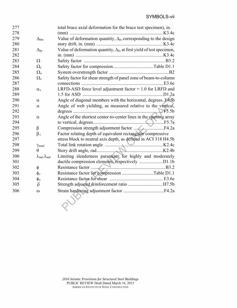
total brace axial deformation for the brace test specimen), in. 277 (mm) ................................................................................ K3.4c 278
bm Value of deformation quantity, b, corresponding to the design 279 story drift, in. (mm) ......................................................... K3.4c 280
by Value of deformation quantity, b, at first yield of test specimen, 281 in. (mm) ........................................................................... K3.4c 282
Safety factor ...................................................................... B3.2 283 c Safety factor for compression ...................................Table D1.1 284 o System overstrength factor ................................................... B2 285 v Safety factor for shear strength of panel zone of beam-to-column 286
connections ...................................................................... E3.6e 287 s LRFD-ASD force level adjustment factor = 1.0 for LRFD and 288
1.5 for ASD ..................................................................... D1.2a 289 Angle of diagonal members with the horizontal, degrees..E4.5b 290 Angle of web yielding, as measured relative to the vertical, 291
degrees ............................................................................. F5.5b 292 Angle of the shortest center-to-center lines in the opening array 293
to vertical, degrees .............................................................F5.7a 294 Compression strength adjustment factor ..........................F4.2a 295 1 Factor relating depth of equivalent rectangular compressive 296
stress block to neutral axis depth, as defined in ACI 318 H4.5b 297 total Total link rotation angle .................................................. K2.4c 298 Story drift angle, rad ......................................................... K2.4b 299 hd, λmd Limiting slenderness parameter for highly and moderately 300
ductile compression elements, respectively .................... D1.1b 301 Resistance factor ................................................................ B3.2 302 c Resistance factor for compression ...........................Table D1.1 303 v Resistance factor for shear .............................................. E3.6e 304 Strength adjusted reinforcement ratio .............................. H7.5b 305
Strain hardening adjustment factor ...................................F4.2a 306

PUBLIC R
EVIEW
ONE D
RAFT
GLOSS-1
2016 Seismic Provisions for Structural Steel Buildings PUBLIC REVIEW Draft Dated March 16, 2015
AMERICAN INSTITUTE OF STEEL CONSTRUCTION
350
351
Glossary 352
353 The terms listed below are to be used in addition to those in the AISC 354 Specification for Structural Steel Buildings. Some commonly used terms are 355 repeated here for convenience. 356 357 Notes: 358 (1) Terms designated with † are common AISI-AISC terms that are coordinated 359
between the two standards developers. 360 (2) Terms designated with * are usually qualified by the type of load effect, for 361
example, nominal tensile strength, available compressive strength, design flexural 362 strength. 363
364 Adjusted brace strength. Strength of a brace in a buckling-restrained braced 365
frame at deformations corresponding to 2.0 times the design story drift. 366
Adjusted link shear strength. Link shear strength including the material 367 overstrength and strain hardening. 368
Allowable strength*†. Nominal strength divided by the safety factor, Rn / . 369
370
Applicable building code†. Building code under which the structure is designed. 371
ASD (allowable strength design)†. Method of proportioning structural 372 components such that the allowable strength equals or exceeds the 373 required strength of the component under the action of the ASD load 374 combinations. 375
ASD load combination†. Load combination in the applicable building code 376 intended for allowable strength design (allowable stress design). 377
Authority having jurisdiction (AHJ). Organization, political subdivision, office 378 or individual charged with the responsibility of administering and 379 enforcing the provisions of this Standard. 380
Available strength*†. Design strength or allowable strength, as applicable. 381
Boundary member. Portion along wall or diaphragm edge strengthened with 382 structural steel sections and/or longitudinal steel reinforcement and 383 transverse reinforcement. 384
Brace test specimen. A single buckling-restrained brace element used for 385 laboratory testing intended to model the brace in the prototype. 386
Braced frame†. An essentially vertical truss system that provides resistance to 387 lateral forces and provides stability for the structural system. 388
Buckling-restrained brace. A pre-fabricated, or manufactured, brace element 389 consisting of a steel core and a buckling-restraining system as described in 390 Section F4 and qualified by testing as required in Section K3. 391
PUBLIC R
EVIEW
ONE D
RAFT
GLOSS-2
2016 Seismic Provisions for Structural Steel Buildings PUBLIC REVIEW Draft Dated March 16, 2015
AMERICAN INSTITUTE OF STEEL CONSTRUCTION
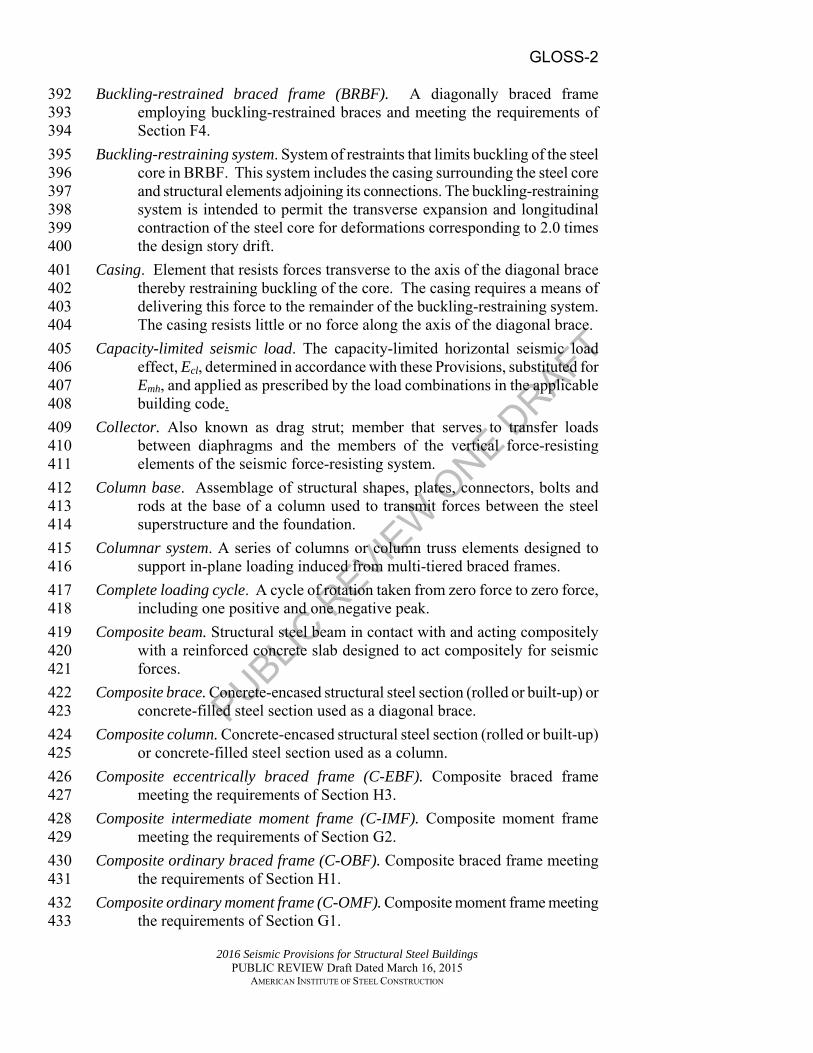
Buckling-restrained braced frame (BRBF). A diagonally braced frame 392 employing buckling-restrained braces and meeting the requirements of 393 Section F4. 394
Buckling-restraining system. System of restraints that limits buckling of the steel 395 core in BRBF. This system includes the casing surrounding the steel core 396 and structural elements adjoining its connections. The buckling-restraining 397 system is intended to permit the transverse expansion and longitudinal 398 contraction of the steel core for deformations corresponding to 2.0 times 399 the design story drift. 400
Casing. Element that resists forces transverse to the axis of the diagonal brace 401 thereby restraining buckling of the core. The casing requires a means of 402 delivering this force to the remainder of the buckling-restraining system. 403 The casing resists little or no force along the axis of the diagonal brace. 404
Capacity-limited seismic load. The capacity-limited horizontal seismic load 405 effect, Ecl, determined in accordance with these Provisions, substituted for 406 Emh, and applied as prescribed by the load combinations in the applicable 407 building code. 408
Collector. Also known as drag strut; member that serves to transfer loads 409 between diaphragms and the members of the vertical force-resisting 410 elements of the seismic force-resisting system. 411
Column base. Assemblage of structural shapes, plates, connectors, bolts and 412 rods at the base of a column used to transmit forces between the steel 413 superstructure and the foundation. 414
Columnar system. A series of columns or column truss elements designed to 415 support in-plane loading induced from multi-tiered braced frames. 416
Complete loading cycle. A cycle of rotation taken from zero force to zero force, 417 including one positive and one negative peak. 418
Composite beam. Structural steel beam in contact with and acting compositely 419 with a reinforced concrete slab designed to act compositely for seismic 420 forces. 421
Composite brace. Concrete-encased structural steel section (rolled or built-up) or 422 concrete-filled steel section used as a diagonal brace. 423
Composite column. Concrete-encased structural steel section (rolled or built-up) 424 or concrete-filled steel section used as a column. 425
Composite eccentrically braced frame (C-EBF). Composite braced frame 426 meeting the requirements of Section H3. 427
Composite intermediate moment frame (C-IMF). Composite moment frame 428 meeting the requirements of Section G2. 429
Composite ordinary braced frame (C-OBF). Composite braced frame meeting 430 the requirements of Section H1. 431
Composite ordinary moment frame (C-OMF). Composite moment frame meeting 432 the requirements of Section G1. 433

PUBLIC R
EVIEW
ONE D
RAFT
GLOSS-3
2016 Seismic Provisions for Structural Steel Buildings PUBLIC REVIEW Draft Dated March 16, 2015
AMERICAN INSTITUTE OF STEEL CONSTRUCTION
Composite ordinary shear wall (C-OSW). Composite shear wall meeting the 434 requirements of Section H4. 435
Composite partially restrained moment frame (C-PRMF). Composite moment 436 frame meeting the requirements of Section G4. 437
Composite plate shear wall (C-PSW). Wall consisting of steel plate with 438 reinforced concrete encasement on one or both sides that provides out-of-439 plane stiffening to prevent buckling of the steel plate and meeting the 440 requirements of Section H6. 441
Composite shear wall. Steel plate wall panel composite with reinforced concrete 442 wall panel or reinforced concrete wall that has steel or concrete-encased 443 structural steel sections as boundary members. 444
Composite slab. Reinforced concrete slab supported on and bonded to a formed 445 steel deck that acts as a diaphragm to transfer load to and between 446 elements of the seismic force resisting system. 447
Composite special concentrically braced frame (C-SCBF). Composite braced 448 frame meeting the requirements of Section H2. 449
Composite special moment frame (C-SMF). Composite moment frame meeting 450 the requirements of Section G3. 451
Composite special shear wall (C-SSW). Composite shear wall meeting the 452 requirements of Section H5. 453
Concrete-encased shapes. Structural steel sections encased in concrete. 454
Continuity plates. Column stiffeners at the top and bottom of the panel zone; also 455 known as transverse stiffeners. 456
Coupling beam. Structural steel or composite beam connecting adjacent 457 reinforced concrete wall elements so that they act together to resist lateral 458 loads. 459
Demand critical weld. Weld so designated by these Provisions. 460
Design earthquake ground motion. The ground motion represented by the design 461 response spectrum as specified in the applicable building code. 462
Design story drift. Calculated story drift, including the effect of expected 463 inelastic action, due to design level earthquake forces as determined by the 464 applicable building code. 465
Design strength*†. Resistance factor multiplied by the nominal strength, Rn. 466
Diagonal brace. Inclined structural member carrying primarily axial force in a 467 braced frame. 468
Ductile limit state. Ductile limit states include member and connection yielding, 469 bearing deformation at bolt holes, as well as buckling of members that 470 conform to the seismic compactness limitations of Table D1.1. Rupture of 471 a member or of a connection, or buckling of a connection element, is not a 472 ductile limit state. 473
Eccentrically braced frame (EBF). Diagonally braced frame meeting the 474 requirements of Section F3 that has at least one end of each diagonal brace 475
PUBLIC R
EVIEW
ONE D
RAFT
GLOSS-4
2016 Seismic Provisions for Structural Steel Buildings PUBLIC REVIEW Draft Dated March 16, 2015
AMERICAN INSTITUTE OF STEEL CONSTRUCTION
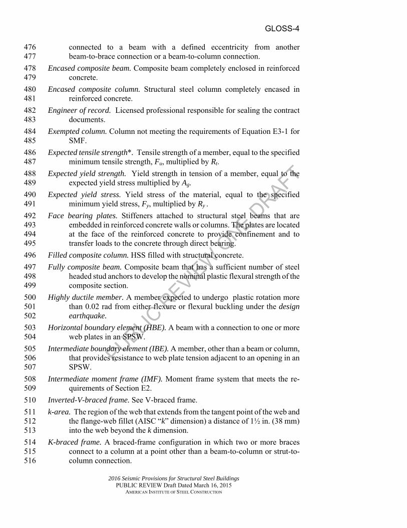
connected to a beam with a defined eccentricity from another 476 beam-to-brace connection or a beam-to-column connection. 477
Encased composite beam. Composite beam completely enclosed in reinforced 478 concrete. 479
Encased composite column. Structural steel column completely encased in 480 reinforced concrete. 481
Engineer of record. Licensed professional responsible for sealing the contract 482 documents. 483
Exempted column. Column not meeting the requirements of Equation E3-1 for 484 SMF. 485
Expected tensile strength*. Tensile strength of a member, equal to the specified 486 minimum tensile strength, Fu, multiplied by Rt. 487
Expected yield strength. Yield strength in tension of a member, equal to the 488 expected yield stress multiplied by Ag. 489
Expected yield stress. Yield stress of the material, equal to the specified 490 minimum yield stress, Fy, multiplied by Ry . 491
Face bearing plates. Stiffeners attached to structural steel beams that are 492 embedded in reinforced concrete walls or columns. The plates are located 493 at the face of the reinforced concrete to provide confinement and to 494 transfer loads to the concrete through direct bearing. 495
Filled composite column. HSS filled with structural concrete. 496
Fully composite beam. Composite beam that has a sufficient number of steel 497 headed stud anchors to develop the nominal plastic flexural strength of the 498 composite section. 499
Highly ductile member. A member expected to undergo plastic rotation more 500 than 0.02 rad from either flexure or flexural buckling under the design 501 earthquake. 502
Horizontal boundary element (HBE). A beam with a connection to one or more 503 web plates in an SPSW. 504
Intermediate boundary element (IBE). A member, other than a beam or column, 505 that provides resistance to web plate tension adjacent to an opening in an 506 SPSW. 507
Intermediate moment frame (IMF). Moment frame system that meets the re-508 quirements of Section E2. 509
Inverted-V-braced frame. See V-braced frame. 510
k-area. The region of the web that extends from the tangent point of the web and 511 the flange-web fillet (AISC “k” dimension) a distance of 1½ in. (38 mm) 512 into the web beyond the k dimension. 513
K-braced frame. A braced-frame configuration in which two or more braces 514 connect to a column at a point other than a beam-to-column or strut-to-515 column connection. 516

PUBLIC R
EVIEW
ONE D
RAFT
GLOSS-5
2016 Seismic Provisions for Structural Steel Buildings PUBLIC REVIEW Draft Dated March 16, 2015
AMERICAN INSTITUTE OF STEEL CONSTRUCTION
Link. In EBF, the segment of a beam that is located between the ends of the 517 connections of two diagonal braces or between the end of a diagonal brace 518 and a column. The length of the link is defined as the clear distance 519 between the ends of two diagonal braces or between the diagonal brace 520 and the column face. 521
Link intermediate web stiffeners. Vertical web stiffeners placed within the link in 522 EBF. 523
Link rotation angle. Inelastic angle between the link and the beam outside of the 524 link when the total story drift is equal to the design story drift. 525
Link rotation angle, total. The relative displacement of one end of the link with 526 respect to the other end (measured transverse to the longitudinal axis of 527 the undeformed link), divided by the link length. The total link rotation 528 angle includes both elastic and inelastic components of deformation of the 529 link and the members attached to the link ends. 530
Link design shear strength. Lesser of the available shear strength of the link 531 based on the flexural or shear strength of the link member. 532
Load-carrying reinforcement. Reinforcement in composite members designed 533 and detailed to resist the required loads. 534
Lowest anticipated service temperature (LAST). Lowest daily minimum 535 temperature, or other suitable temperature, as established by the engineer 536 of record. 537
LRFD (load and resistance factor design)†. Method of proportioning structural 538 components such that the design strength equals or exceeds the required 539 strength of the component under the action of the LRFD load 540 combinations. 541
LRFD load combination†. Load combination in the applicable building code 542 intended for strength design (load and resistance factor design). 543
Material test plate. A test specimen from which steel samples or weld metal 544 samples are machined for subsequent testing to determine mechanical 545 properties. 546
Member brace. Member that provides stiffness and strength to control movement 547 of another member out-of-the plane of the frame at the braced points. 548
Moderately ductile member A member expected to undergo moderate plastic 549 rotation (0.02 rad or less) from either flexure or flexural buckling under 550 the design earthquake. 551
Multi-tiered braced frame. A braced-frame configuration with two or more tiers 552 of bracing between diaphragm levels or locations of out-of-plane bracing. 553
Nominal strength*†. Strength of a structure or component (without the resistance 554 factor or safety factor applied) to resist load effects, as determined in 555 accordance with the Specification. 556
Ordinary cantilever column system (OCCS). A seismic force resisting-system in 557 which the seismic forces are resisted by one or more columns that are 558

PUBLIC R
EVIEW
ONE D
RAFT
GLOSS-6
2016 Seismic Provisions for Structural Steel Buildings PUBLIC REVIEW Draft Dated March 16, 2015
AMERICAN INSTITUTE OF STEEL CONSTRUCTION
cantilevered from the foundation or from the diaphragm level below and 559 that meets the requirements of Section E5. 560
Ordinary concentrically braced frame (OCBF). Diagonally braced frame 561 meeting the requirements of Section F1 in which all members of the 562 braced-frame system are subjected primarily to axial forces. 563
Ordinary moment frame (OMF). Moment frame system that meets the re-564 quirements of Section E1. 565
Overstrength factor, o. Factor specified by the applicable building code in order 566 to determine the overstrength seismic load, where required by these 567 Provisions. 568
Overstrength Seismic Load. The horizontal seismic load effect including 569 overstrength determined using the overstrength factor, Ωo, and applied 570 as prescribed by the load combinations in the applicable building code. 571
Partially composite beam. Steel beam with a composite slab with a nominal 572 flexural strength controlled by the strength of the steel headed stud 573 anchors. 574
Partially-restrained composite connection. Partially restrained (PR) connections 575 as defined in the Specification that connect partially or fully composite 576 beams to steel columns with flexural resistance provided by a force couple 577 achieved with steel reinforcement in the slab and a steel seat angle or 578 comparable connection at the bottom flange. 579
Plastic hinge. Yielded zone that forms in a structural member when the plastic 580 moment is attained. The member is assumed to rotate further as if hinged, 581 except that such rotation is restrained by the plastic moment. 582
Prequalified connection. Connection that complies with the requirements of 583 Section K1 or ANSI/AISC 358. 584
Protected zone. Area of members or connections of members in which 585 limitations apply to fabrication and attachments. 586
Prototype. The connection or diagonal brace that is to be used in the building 587 (SMF, IMF, EBF, BRBF, C-IMF, C-SMF and C-PRMF). 588
Provisions. Refers to this document, the AISC Seismic Provisions for Structural 589 Steel Buildings (ANSI/AISC 341). 590
Quality assurance plan. Written description of qualifications, procedures, quality 591 inspections, resources and records to be used to provide assurance that the 592 structure complies with the engineer's quality requirements, specifications 593 and contract documents. 594
Reduced beam section. Reduction in cross section over a discrete length that 595 promotes a zone of inelasticity in the member. 596
Required strength*. Forces, stresses and deformations acting on a structural 597 component, determined by either structural analysis, for the LRFD or ASD 598 load combinations, as appropriate, or as specified by the Specification and 599 these Provisions. 600

PUBLIC R
EVIEW
ONE D
RAFT
GLOSS-7
2016 Seismic Provisions for Structural Steel Buildings PUBLIC REVIEW Draft Dated March 16, 2015
AMERICAN INSTITUTE OF STEEL CONSTRUCTION
Resistance factor, †. Factor that accounts for unavoidable deviations of the 601 nominal strength from the actual strength and for the manner and 602 consequences of failure. 603
Risk category. Classification assigned to a structure based on its use as specified 604 by the applicable building code. 605
Safety factor, †. Factor that accounts for deviations of the actual strength from 606 the nominal strength, deviations of the actual load from the nominal load, 607 uncertainties in the analysis that transforms the load into a load effect, and 608 for the manner and consequences of failure. 609
Seismic design category. A classification assigned to a structure based on its risk 610 category and the severity of the design earthquake ground motion at the 611 site. 612
Seismic force-resisting system (SFRS). That part of the structural system that has 613 been considered in the design to provide the required resistance to the 614 seismic forces prescribed in the applicable building code. 615
Seismic Response modification coefficient, R. Factor that reduces seismic load 616 effects to strength level as specified by the applicable building code. 617
Special cantilever column system (SCCS). A seismic force resisting-system in 618 which the seismic forces are resisted by one or more columns that are 619 cantilevered from the foundation or from the diaphragm level below and 620 that meets the requirements of Section E6. 621
Special concentrically braced frame (SCBF). Diagonally braced frame meeting 622 the requirements of Section F2 in which all members of the braced-frame 623 system are subjected primarily to axial forces. 624
Special moment frame (SMF). Moment frame system that meets the 625 requirements of Section E3. 626
Special plate shear wall (SPSW). Plate shear wall system that meets the 627 requirements of Section F5. 628
Special truss moment frame (STMF). Truss moment frame system that meets the 629 requirements of Section E4. 630
Specification. Refers to the AISC Specification for Structural Steel Buildings 631 (ANSI/AISC 360). 632
Steel core. Axial-force-resisting element of a buckling-restrained brace. The 633 steel core contains a yielding segment and connections to transfer its axial 634 force to adjoining elements; it is permitted to also contain projections 635 beyond the casing and transition segments between the projections and 636 yielding segment. 637
Story drift angle. Interstory displacement divided by story height. 638
Strut. A horizontal member in a multi-tiered braced frame interconnecting brace 639 connection points at columns. 640
PUBLIC R
EVIEW
ONE D
RAFT
GLOSS-8
2016 Seismic Provisions for Structural Steel Buildings PUBLIC REVIEW Draft Dated March 16, 2015
AMERICAN INSTITUTE OF STEEL CONSTRUCTION
Subassemblage test specimen. The combination of members, connections and 641 testing apparatus that replicate as closely as practical the boundary 642 conditions, loading and deformations in the prototype. 643
Test setup. The supporting fixtures, loading equipment and lateral bracing used 644 to support and load the test specimen. 645
Test specimen. A member, connection or subassemblage test specimen. 646
Test subassemblage. The combination of the test specimen and pertinent portions 647 of the test setup. 648
V-braced frame. Concentrically braced frame (SCBF, OCBF, BRBF, C-OBF or 649 C-SCBF) in which a pair of diagonal braces located either above or below 650 a beam is connected to a single point within the clear beam span. Where 651 the diagonal braces are below the beam, the system is also referred to as 652 an inverted-V-braced frame. 653
Vertical boundary element (VBE). A column with a connection to one or more 654 web plates in an SPSW. 655
X-braced frame. Concentrically braced frame (OCBF, SCBF, C-OBF or C-656 SCBF) in which a pair of diagonal braces crosses near the mid-length of 657 the diagonal braces. 658
Yield length ratio. In a buckling-restrained brace, the ratio of the length over 659 which the core area is equal to Asc, to the length from intersection points of 660 brace centerline and beam or column centerline at each end. 661

PUBLIC R
EVIEW
ONE D
RAFT
ACRONYMS-1
2016 Seismic Provisions for Structural Steel Buildings PUBLIC REVIEW Draft Dated March 16, 2015
AMERICAN INSTITUTE OF STEEL CONSTRUCTION
700
ACRONYMS AND ABBREVIATIONS 701
702 The following acronyms appear in the AISC Seismic Provisions for Structural 703 Steel Buildings. The acronyms are written out where they first appear within a 704 Section. 705 706 ACI (American Concrete Institute) 707 AISC (American Institute of Steel Construction) 708 ANSI (American National Standards Institute) 709 ASCE (American Society of Civil Engineers) 710 ASD (allowable strength design) 711 AWS (American Welding Society) 712 BRBF (buckling-restrained braced frame) 713 C-EBF (composite eccentrically braced frame) 714 C-IMF (composite intermediate moment frame) 715 CJP (complete joint penetration) 716 C-OBF (composite ordinary braced frame) 717 C-OMF (composite ordinary moment frame) 718 C-OSW (composite ordinary shear wall) 719 C-PRMF (composite partially restrained moment frame) 720 CPRP (connection prequalification review panel) 721 C-PSW (composite plate shear wall) 722 C-SCBF (composite special concentrically braced frame) 723 C-SMF (composite special moment frame) 724 C-SSW (composite special shear wall) 725 CVN (Charpy V-notch) 726 EBF (eccentrically braced frame) 727 FCAW (flux cored arc welding) 728 FEMA (Federal Emergency Management Agency) 729 FR (fully restrained) 730 GMAW (gas metal arc welding) 731 HBE (horizontal boundary element) 732 HSS (hollow structural section) 733 IBE (intermediate boundary element) 734 IMF (intermediate moment frame) 735 LAST (lowest anticipated service temperature) 736 LRFD (load and resistance factor design) 737 MT (magnetic particle testing) 738 NDT (nondestructive testing) 739 OCBF (ordinary concentrically braced frame) 740 OCCS (ordinary cantilever column system) 741 OMF (ordinary moment frame) 742 OVS (oversized) 743 PJP (partial joint penetration) 744 PR (partially restrained) 745

PUBLIC R
EVIEW
ONE D
RAFT
ACRONYMS-2
2016 Seismic Provisions for Structural Steel Buildings PUBLIC REVIEW Draft Dated March 16, 2015
AMERICAN INSTITUTE OF STEEL CONSTRUCTION
QA (quality assurance) 746 QC (quality control) 747 RBS (reduced beam section) 748 RCSC (Research Council on Structural Connections) 749 750 SCBF (special concentrically braced frame) 751 SCCS (special cantilever column system) 752 SDC (seismic design category) 753 SEI (Structural Engineering Institute) 754 SFRS (seismic force-resisting system) 755 SMAW (shielded metal arc welding) 756 SMF (special moment frame) 757 SPSPW (special perforated steel plate wall) 758 SPSW (special plate shear wall) 759 SRC (steel-reinforced concrete) 760 STMF (special truss moment frame) 761 UT (ultrasonic testing) 762 VBE (vertical boundary element) 763 WPQR (welder performance qualification records) 764 WPS (welding procedure specification) 765

PUBLIC R
EVIEW
ONE D
RAFT
A-1
2016 Seismic Provisions for Structural Steel Buildings PUBLIC REVIEW Draft Dated March 16, 2015
AMERICAN INSTITUTE OF STEEL CONSTRUCTION
800
801
CHAPTER A 802
GENERAL REQUIREMENTS 803
804 This chapter states the scope of the Provisions, summarizes referenced 805 specification, code and standard documents, and provides requirements for 806 materials and contract documents. 807 808 The chapter is organized as follows: 809 810
A1. Scope 811 A2. Referenced Specifications, Codes and Standards 812 A3. Materials 813 A4. Structural Design Drawings and Specifications 814
A1. SCOPE 815
The Seismic Provisions for Structural Steel Buildings, hereafter referred 816 to as these Provisions, shall govern the design, fabrication and erection of 817 structural steel members and connections in the seismic force-resisting 818 systems (SFRS), and splices and bases of columns in gravity framing 819 systems of buildings and other structures with moment frames, braced 820 frames and shear walls. Other structures are defined as those structures 821 designed, fabricated and erected in a manner similar to buildings, with 822 building-like vertical and lateral force-resisting elements. These 823 Provisions shall apply to the design of seismic force-resisting systems of 824 structural steel or of structural steel acting compositely with reinforced 825 concrete, unless specifically exempted by the applicable building code. 826
Wherever these Provisions refer to the applicable building code and there 827 is none, the loads, load combinations, system limitations, and general 828 design requirements shall be those in ASCE/SEI 7. 829
830 User Note: ASCE/SEI 7 (Table 12.2-1, Item H) specifically exempts 831 structural steel systems in seismic design categories B and C from the 832 requirements in these Provisions if they are designed according to the 833 Specification for Structural Steel Buildings and the seismic loads are 834 computed using a seismic response modification factor, R, of 3; 835 composite systems are not covered by this exemption. These Provisions 836 do not apply in seismic design category A. 837
838

PUBLIC R
EVIEW
ONE D
RAFT
A-2
2016 Seismic Provisions for Structural Steel Buildings PUBLIC REVIEW Draft Dated March 16, 2015
AMERICAN INSTITUTE OF STEEL CONSTRUCTION
839 User Note: ASCE/SEI 7 (Table 12.2-1, Item H) specifically exempts 840 structural steel systems, but not composite systems, from these Provisions 841 in seismic design categories B and C if they are designed in accordance 842 with the Specification for Structural Steel Buildings and the seismic loads 843 are computed using a response modification coefficient, R, of 3. These 844 Provisions do not apply in seismic design category A.. 845 846 847 User Note: ASCE/SEI (Table 15.4-1) permits certain nonbuilding 848 structures to be designed in accordance with the Specification for 849 Structural Steel Buildings in lieu of the Provisions with an appropriately 850 reduced R factor. 851 852 User Note: Composite seismic force resisting systems include those 853 systems with members of structural steel acting compositely with 854 reinforced concrete, as well as systems in which structural steel members 855 and reinforced concrete members act together to form a seismic force-856 resisting system. 857
858 These Provisions shall be applied in conjunction with the AISC 859 Specification for Structural Steel Buildings, hereafter referred to as the 860 Specification. All requirements of the Specification are applicable unless 861 otherwise stated in these Provisions. Members and connections of the 862 SFRS shall satisfy the requirements of the applicable building code, the 863 Specification, and these Provisions. The phrases “is permitted” and “are 864 permitted” in these Provisions identify provisions that comply with the 865 Specification, but are not mandatory. 866
Building Code Requirements for Structural Concrete (ACI 318), as 867 modified in these Provisions, shall be used for the design and 868 construction of reinforced concrete components in composite 869 construction. For the SFRS in composite construction incorporating 870 reinforced concrete components designed in accordance with ACI 318, 871 the requirements of Specification Section B3.1, Design for Strength 872 Using Load and Resistance Factor Design, shall be used. 873
A2. REFERENCED SPECIFICATIONS, CODES AND STANDARDS 874
The documents referenced in these Provisions shall include those listed in 875 Specification Section A2 with the following additions: 876
American Institute of Steel Construction (AISC) 877 ANSI/AISC 360-10 Specification for Structural Steel Buildings 878 ANSI/AISC 358-10 Prequalified Connections for Special and 879 Intermediate Steel Moment Frames for Seismic Applications 880 881

PUBLIC R
EVIEW
ONE D
RAFT
A-3
2016 Seismic Provisions for Structural Steel Buildings PUBLIC REVIEW Draft Dated March 16, 2015
AMERICAN INSTITUTE OF STEEL CONSTRUCTION
American Welding Society (AWS) 882 AWS D1.8/D1.8M:2015 Structural Welding Code—Seismic Supplement 883 AWS B4.0:2015 Standard Methods for Mechanical Testing of Welds 884 (U.S. Customary Units) 885 AWS B4.0M:2000 Standard Methods for Mechanical Testing of Welds 886 (Metric Customary Units) 887 AWS D1.4/D1.4M:2005 Structural Welding Code—Reinforcing Steel 888

PUBLIC R
EVIEW
ONE D
RAFT
A-4
2016 Seismic Provisions for Structural Steel Buildings PUBLIC REVIEW Draft Dated March 16, 2015
AMERICAN INSTITUTE OF STEEL CONSTRUCTION
A3. MATERIALS 889
A3.1. Material Specifications 890
Structural steel used in the seismic force-resisting system (SFRS) shall 891 satisfy the requirements of Specification Section A3.1, except as 892 modified in these Provisions. The specified minimum yield stress of 893 structural steel to be used for members in which inelastic behavior is 894 expected shall not exceed 50 ksi (345 MPa) for systems defined in 895 Chapters E, F, G and H, except that for systems defined in Sections E1, 896 F1, G1, H1 and H4 this limit shall not exceed 55 ksi (380 MPa). Either of 897 these specified minimum yield stress limits are permitted to be exceeded 898 when the suitability of the material is determined by testing or other 899 rational criteria. 900
Exception: Specified minimum yield stress of structural steel shall not 901 exceed 70 ksi (450 MPa) for columns in systems defined in Sections E3, 902 E4, G3, H1, H2 and H3, and for columns in all systems in Chapter F. 903
The structural steel used in the SFRS described in Chapters E, F, G and H 904 shall meet one of the following ASTM Specifications: 905 906 (1) Hot-rolled structural shapes 907 908
ASTM A36/A36M 909 ASTM A529/A529M 910 ASTM A572/A572M [Gr. 42 (290), 50 (345) or 55 (380)] 911 ASTM A588/A588M 912 ASTM A913/A913M [Gr. 50 (345), 60 (415), 65 (450) or 70 913 (485)] 914 ASTM A992/A992M 915
916 (2) Hollow structural sections (HSS) 917 ASTM A500/A500M (Gr. B or C) 918 ASTM A501 919
ASTM A1085/A1085M 920 ASTM A53/A53M 921
922 (3) Plates 923
924 ASTM A36/A36M 925 ASTM A529/A529M 926 ASTM A572/A572M [Gr. 42 (290), 50 (345) or 55 (380)] 927 ASTM A588/A588M 928 ASTM A1011/A1011M HSLAS Gr. 55 (380) 929 ASTM A1043/A1043M 930 931

PUBLIC R
EVIEW
ONE D
RAFT
A-5
2016 Seismic Provisions for Structural Steel Buildings PUBLIC REVIEW Draft Dated March 16, 2015
AMERICAN INSTITUTE OF STEEL CONSTRUCTION
(4) Bars 932 933
ASTM A36/A36M 934 ASTM A529/A529M 935 ASTM A572/A572M [Gr. 42 (290), 50 (345) or 55 (380)] 936 ASTM A588/A588M 937 938 (5) Sheets 939
940 ASTM A1011/A1011M HSLAS Gr. 55 (380) 941
The structural steel used for column base plates shall meet one of the 942 preceding ASTM specifications or ASTM A283/A283M Grade D. 943
Other steels and nonsteel materials in buckling-restrained braced frames 944 are permitted to be used subject to the requirements of Sections F4 and 945 K3. 946
User Note: This section only covers material properties for structural 947 steel used in the SFRS and included in the definition of structural steel 948 given in Section 2.1 of the AISC Code of Standard Practice. Other steel, 949 such as cables for permanent bracing, is not covered. Steel reinforcement 950 used in components in composite SFRS is covered in Section A3.6. 951
A3.2. Expected Material Strength 952
When required in these Provisions, the required strength of an element (a 953 member or a connection of a member) shall be determined from the 954 expected yield stress, RyFy, of the member or an adjoining member, as 955 applicable, where Fy is the specified minimum yield stress of the steel to 956 be used in the member and Ry is the ratio of the expected yield stress to 957 the specified minimum yield stress, Fy, of that material. 958
When required to determine the nominal strength, Rn, for limit states 959 within the same member from which the required strength is determined, 960 the expected yield stress, RyFy, and the expected tensile strength, RtFu, are 961 permitted to be used in lieu of Fy and Fu, respectively, where Fu is the 962 specified minimum tensile strength and Rt is the ratio of the expected 963 tensile strength to the specified minimum tensile strength, Fu, of that 964 material. 965
User Note: In several instances a member, or a connection limit state 966 within that member, is required to be designed for forces corresponding 967 to the expected strength of the member itself. Such cases include 968 determination of the nominal strength, Rn, of the beam outside of the link 969 in EBF, diagonal brace rupture limit states (block shear rupture and net 970 section rupture in the diagonal brace in SCBF), etc. In such cases it is 971 permitted to use the expected material strength in the determination of 972

PUBLIC R
EVIEW
ONE D
RAFT
A-6
2016 Seismic Provisions for Structural Steel Buildings PUBLIC REVIEW Draft Dated March 16, 2015
AMERICAN INSTITUTE OF STEEL CONSTRUCTION
available member strength. For connecting elements and for other 973 members, specified material strength should be used. 974
The values of Ry and Rt for various steel and steel reinforcement materials 975 are given in Table A3.1. Other values of Ry and Rt are permitted if the 976 values are determined by testing of specimens, similar in size and source 977 to the materials to be used, conducted in accordance with the testing 978 requirements per the ASTM specifications for the specified grade of 979 steel. 980
981

PUBLIC R
EVIEW
ONE D
RAFT
A-7
2016 Seismic Provisions for Structural Steel Buildings PUBLIC REVIEW Draft Dated March 16, 2015
AMERICAN INSTITUTE OF STEEL CONSTRUCTION
TABLE A3.1 Ry and Rt Values for Steel and Steel
Reinforcement Materials
Application Ry Rt
Hot-rolled structural shapes and bars:
ASTM A36/A36M 1.5 1.2
ASTM A1043/1043M Gr. 36 (250) 1.3 1.1
ASTM A992/A992M 1.1 1.1
ASTM A572/572M Gr. 50 (345) or 55 (380) 1.1 1.1
ASTM A913/A913M Gr. 50 (345), 60 (415), 65 (450), or 70 (485)
1.1 1.1
ASTM A588/A588M 1.1 1.1
ASTM A1043/A1043M Gr. 50 (345) 1.2 1.1
ASTM A529 Gr. 50 (345) 1.2 1.2
ASTM A529 Gr. 55 (380) 1.1 1.2
Hollow structural sections (HSS):
ASTM A500/A500M Gr. B
ASTM A500/A500M Gr. C
ASTM A501
1.4
1.3
1.4
1.3
1.2
1.3
ASTM A53/A53M
ASTM A1085/A1085M
1.6
1.2
1.2
1.1
Plates, Strips and Sheets: ASTM A36/A36M 1.3 1.2 ASTM A1043/1043M Gr. 36 (250) 1.3 1.1 ASTM A1011/A1011M HSLAS Gr. 55 (380) 1.1 1.1 ASTM A572/A572M Gr. 42 (290) 1.3 1.0 ASTM A572/A572M Gr. 50 (345), Gr. 55
(380) 1.1 1.2
ASTM A588/A588M 1.1 1.2 ASTM 1043/1043M Gr. 50 (345) 1.2 1.1
Steel Reinforcement: ASTM A615/A615M Gr. 60 (420) 1.2 1.2

PUBLIC R
EVIEW
ONE D
RAFT
A-8
2016 Seismic Provisions for Structural Steel Buildings PUBLIC REVIEW Draft Dated March 16, 2015
AMERICAN INSTITUTE OF STEEL CONSTRUCTION
ASTM A615/A615M Gr. 75 (520) and Gr. 80 (550)
1.1 1.2
ASTM A706/A706M Gr. 60 (420) and Gr. 80 (550)
1.2 1.2
User Note: The expected compressive strength of concrete may be 982 estimated using values from Seismic Rehabilitation of Existing Buildings, 983 ASCE/SEI 41--06. 984
A3.3. Heavy Sections 985
For structural steel in the SFRS, in addition to the requirements of 986 Specification Section A3.1c, hot rolled shapes with flange thickness equal 987 to or greater than 12 in. (38 mm) shall have a minimum Charpy V-notch 988 toughness of 20 ft-lb (27 J) at 70F (21C), tested in the alternate core 989 location as described in ASTM A6 Supplementary Requirement S30. 990 Plates with thickness equal to or greater than 2 in. (50 mm) shall have a 991 minimum Charpy V-notch toughness of 20 ft-lb (27 J) at 70F (21C), 992 measured at any location permitted by ASTM A673, Frequency P, where 993 the plate is used for the following: 994
995 (a) Members built up from plate 996 (b) Connection plates where inelastic strain under seismic loading is 997
expected 998 (c) The steel core of buckling-restrained braces 999
A3.4. Consumables for Welding 1000
A3.4a. Seismic Force-Resisting System Welds 1001 1002 All welds used in members and connections in the SFRS shall be made 1003 with filler metals meeting the requirements specified in clause 6.3 of 1004 Structural Welding Code—Seismic Supplement (AWS D1.8/D1.8M), 1005 hereafter referred to as AWS D1.8/D1.8M. 1006 1007 User Note: AWS D1.8/D1.8M clauses 6.3.5, 6.3.6, 6.3.7 and 6.3.8 apply 1008 only to demand critical welds. 1009
1010 A3.4b. Demand Critical Welds 1011
1012 Welds designated as demand critical shall be made with filler metals 1013 meeting the requirements specified in AWS D1.8/D1.8M clause 6.3.1014

PUBLIC R
EVIEW
ONE D
RAFT
A-9
2016 Seismic Provisions for Structural Steel Buildings PUBLIC REVIEW Draft Dated March 16, 2015
AMERICAN INSTITUTE OF STEEL CONSTRUCTION
1015 1016 User Note: AWS D1.8/D1.8M requires that all seismic force-resisting 1017 system welds are to be made with filler metals classified using AWS A5 1018 standards that achieve the following mechanical properties: 1019 1020
Filler Metal Classification Properties for Seismic Force-Resisting System Welds
Property Classification
70 ksi (480 MPa)
80 ksi (550 MPa)
Yield Strength, ksi (MPa) 58 (400) min. 68 (470) min.
Tensile Strength, ksi (MPa)
70 (480) min. 80 (550) min.
Elongation, % 22 min. 19 min. CVN Toughness, ft-lb (J)
20 (27) min. @ 0 °F (–18°C) a
a Filler metals classified as meeting 20 ft-lbf (27 J) min. at a temperature lower than 0 °F (–18°C) also meet this requirement.
1021 In addition to the above requirements, AWS D1.8/D1.8M requires, unless 1022 otherwise exempted from testing, that all demand critical welds are to be 1023 made with filler metals receiving Heat Input Envelope Testing that 1024 achieve the following mechanical properties in the weld metal: 1025 1026
Mechanical Properties for Demand Critical Welds
Property Classification
70 ksi (480 MPa)
80 ksi (550 MPa)
Yield Strength, ksi (MPa) 58 (400) min. 68 (470) min.
Tensile Strength, ksi (MPa)
70 (480) min. 80 (550) min.
Elongation (%) 22 min. 19 min. CVN Toughness, ft-lb (J)
40 (54) min. @ 70°F (20°C) b, c
b For LAST of +50°F (+10°C). For LAST less than + 50°F (+10°C), see AWS D1.8/D1.8M clause 6.3.6.
c Tests conducted in accordance with AWS D1.8/D1.8M Annex A meeting 40 ft-lb (54 J) min. at a temperature lower than +70°F (+20°C) also meet this requirement.
1027
A3.5. Concrete and Steel Reinforcement 1028
Concrete and steel reinforcement used in composite components in 1029 composite intermediate or special SFRS of Sections G2, G3, G4, H2, H3, 1030 H5 and H6 shall satisfy the requirements of ACI 318 Chapter 18. 1031 Concrete and steel reinforcement used in composite components in 1032

PUBLIC R
EVIEW
ONE D
RAFT
A-10
2016 Seismic Provisions for Structural Steel Buildings PUBLIC REVIEW Draft Dated March 16, 2015
AMERICAN INSTITUTE OF STEEL CONSTRUCTION
composite ordinary SFRS of Sections G1, H1 and H4 shall satisfy the 1033 requirements of ACI 318 Section 18.2.1.4. 1034
A4. STRUCTURAL DESIGN DRAWINGS AND SPECIFICATIONS 1035
A4.1. General 1036
Structural design drawings and specifications shall indicate the work to 1037 be performed, and include items required by the Specification, the AISC 1038 Code of Standard Practice for Steel Buildings and Bridges, the applicable 1039 building code, and the following, as applicable: 1040
(1) Designation of the SFRS 1041
(2) Identification of the members and connections that are part of the 1042 SFRS 1043
(3) Locations and dimensions of protected zones, including a 1044 statement that the owner or owner’s designated representative for 1045 construction permanently mark the protected zone 1046
(4) Connection details between concrete floor diaphragms and the 1047 structural steel elements of the SFRS 1048
(5) Shop drawing and erection drawing requirements not addressed in 1049 Section I1 1050
A4.2. Steel Construction 1051
In addition to the requirements of Section A4.1, structural design 1052 drawings and specifications for steel construction shall indicate the 1053 following items, as applicable: 1054
(1) Configuration of the connections 1055
(2) Connection material specifications and sizes 1056
(3) Locations of demand critical welds 1057
(4) Locations where gusset plates are to be detailed to accommodate 1058 inelastic rotation 1059
(5) Locations of connection plates requiring Charpy V-notch 1060 toughness in accordance with Section A3.3(b) 1061
(6) Lowest anticipated service temperature (LAST) of the steel 1062 structure, if the structure is not enclosed and maintained at a 1063 temperature of 50F (10C) or higher 1064
(7) Locations where weld backing is required to be removed 1065
PUBLIC R
EVIEW
ONE D
RAFT
A-11
2016 Seismic Provisions for Structural Steel Buildings PUBLIC REVIEW Draft Dated March 16, 2015
AMERICAN INSTITUTE OF STEEL CONSTRUCTION
(8) Locations where fillet welds are required when weld backing is 1066 permitted to remain 1067
(9) Locations where fillet welds are required to reinforce groove 1068 welds or to improve connection geometry 1069
(10) Locations where weld tabs are required to be removed 1070
(11) Splice locations where tapered transitions are required 1071
(12) The shape of weld access holes, if a shape other than those 1072 provided for in the Specification is required 1073
(13) Joints or groups of joints in which a specific assembly order, 1074 welding sequence, welding technique or other special precautions 1075 where such items are designated to be submitted to the engineer of 1076 record 1077
1078 A4.3. Composite Construction 1079
In addition to the requirements of Section A4.1, and the requirements of 1080 Section A4.2 as applicable for the steel components of reinforced 1081 concrete or composite elements, structural design drawings and 1082 specifications for composite construction shall indicate the following 1083 items, as applicable: 1084
(1) Bar placement, cutoffs, lap and mechanical splices, hooks and 1085 mechanical anchorage, placement of ties and other transverse 1086 reinforcement 1087
(2) Requirements for dimensional changes resulting from 1088 temperature changes, creep and shrinkage 1089
(3) Location, magnitude and sequencing of any prestressing or post-1090 tensioning present 1091
(4) Location of steel headed stud anchors and welded reinforcing bar 1092 anchors 1093
PUBLIC R
EVIEW
ONE D
RAFT
B-1
2016 Seismic Provisions for Structural Steel Buildings PUBLIC REVIEW Draft Dated March 16, 2015
AMERICAN INSTITUTE OF STEEL CONSTRUCTION
1200
1201
CHAPTER B 1202
GENERAL DESIGN REQUIREMENTS 1203
This chapter addresses the general requirements for the seismic design of steel 1204 structures that are applicable to all chapters of the Provisions. 1205
This chapter is organized as follows: 1206 1207 B1. General Seismic Design Requirements 1208 B2. Loads and Load Combinations 1209 B3. Design Basis 1210 B4. System Type 1211 1212
B1. GENERAL SEISMIC DESIGN REQUIREMENTS 1213
The required strength and other seismic design requirements for seismic 1214 design categories, risk categories, and the limitations on height and 1215 irregularity shall be as specified in the applicable building code. 1216
The design story drift and the limitations on story drift shall be 1217 determined as required in the applicable building code. 1218
B2. LOADS AND LOAD COMBINATIONS 1219
Where the required strength defined in these Provisions refers to the 1220 “overstrength seismic load,” the horizontal seismic load effect including 1221 overstrength shall be determined using the overstrength factor, Ωo, and 1222 applied as prescribed by the load combinations in the applicable building 1223 code. Where the required strength defined in these Provisions refers to 1224 the “capacity-limited seismic load,” the capacity-limited horizontal 1225 seismic load effect, Ecl, shall be determined in accordance with these 1226 Provisions, substituted for Emh, and applied as prescribed by the load 1227 combinations in the applicable building code. 1228
User Note: The seismic load effect including overstrength is defined in 1229 ASCE/SEI 7, Section 12.4.3. In ASCE/SEI 7 Section 12.4.3.1, the 1230 horizontal seismic load effect, Emh, is determined using Equation 12.4-7: 1231
mh o EE Q . There is a cap on the value of Emh: it need not be taken larger 1232 than Ecl. Thus, in effect, where these Provisions refer to “overstrength 1233 seismic load,” Emh is permitted to be based upon the overstrength factor, 1234 Ωo, or Ecl. However, where “capacity-limited seismic load” is required, it 1235 is intended that Ecl replace Emh as specified in ASCE/SEI 7 Section 1236 12.4.3.2 and use of ASCE/SEI 7 Equation 12.4-7 is not permitted. 1237

PUBLIC R
EVIEW
ONE D
RAFT
B-2
2016 Seismic Provisions for Structural Steel Buildings PUBLIC REVIEW Draft Dated March 16, 2015
AMERICAN INSTITUTE OF STEEL CONSTRUCTION
In composite construction, incorporating reinforced concrete components 1238 designed in accordance with the requirements of ACI 318, the 1239 requirements of Specification Section B3.1, Design for Strength Using 1240 Load and Resistance Factor Design, shall be used for the seismic force-1241 resisting system (SFRS). 1242
B3. DESIGN BASIS 1243
B3.1. Required Strength 1244
The required strength of structural members and connections shall 1245 be the greater of: 1246
(a) The required strength as determined by structural analysis for the 1247 applicable load combinations, as stipulated in the applicable 1248 building code, and in Chapter C. 1249
(b) The required strength given in Chapters D, E, F, G and H. 1250
B3.2. Available Strength 1251
The available strength is stipulated as the design strength, Rn, for design 1252 in accordance with the provisions for load and resistance factor design 1253 (LRFD) and the allowable strength, Rn /, for design in accordance with 1254 the provisions for allowable strength design (ASD). The available 1255 strength of systems, members and connections shall be determined in 1256 accordance with the Specification, except as modified throughout these 1257 Provisions. 1258
B4. SYSTEM TYPE 1259
The seismic force-resisting system (SFRS) shall contain one or more 1260 moment frame, braced frame or shear wall system conforming to the 1261 requirements of one of the seismic systems designated in Chapters E, F, 1262 G and H. 1263
B5. DIAPHRAGMS, CHORDS AND COLLECTORS 1264
B5.1. General 1265
Diaphragm collectors and all members and connections of truss 1266 diaphragms shall be designed for the load combinations in the applicable 1267 building code, including overstrength. 1268
B5.2. Truss Diaphragms 1269
When a truss is used as a diaphragm, all members of the truss and their 1270 connections shall be designed for forces calculated using the load 1271 combinations of the applicable building code, including overstrength. 1272
Exceptions: 1273

PUBLIC R
EVIEW
ONE D
RAFT
B-3
2016 Seismic Provisions for Structural Steel Buildings PUBLIC REVIEW Draft Dated March 16, 2015
AMERICAN INSTITUTE OF STEEL CONSTRUCTION
(a) The forces specified in this section need not be applied to the 1274 diagonal members of the truss diaphragms and their connections 1275 where these members and connections conform to the 1276 requirements of Sections F2.4a, F2.5a, F2.5b and F2.6c. Braces in 1277 K- or V- configurations are not permitted under this exception. 1278
1279 User Note: Chords in truss diaphragms serve a function 1280 analogous to columns in vertical SCBF, and should meet the 1281 requirements for highly ductile members as required for columns 1282 in Section F2.5a. 1283
1284 (b) The forces specified in this section need not be applied to truss 1285
diaphragms designed as a part of a three-dimensional system in 1286 which the seismic force-resisting system types consist of OMF, 1287 OCBF, or combinations thereof, and truss diagonal members 1288 conform to Sections F1.4b and F1.5 and connections conform to 1289 Section F1.6. 1290
1291 1292

PUBLIC R
EVIEW
ONE D
RAFT
C-1
Seismic Provisions for Structural Steel Buildings PUBLIC REVIEW Draft Dated March 16, 2015
AMERICAN INSTITUTE OF STEEL CONSTRUCTION
CHAPTER C 1400
ANALYSIS 1401
1402
This chapter addresses design related analysis requirements. The chapter is 1403 organized as follows: 1404
1405 C1. General Requirements 1406 C2. Additional Requirements 1407 C3. Nonlinear Analysis 1408
C1. GENERAL REQUIREMENTS 1409
An analysis conforming to the requirements of the applicable building 1410 code and the Specification shall be performed for design of the system. 1411 1412 When the design is based upon elastic analysis, the stiffness properties of 1413 component members of steel systems shall be based on elastic sections 1414 and those of composite systems shall include the effects of cracked 1415 sections. 1416
C2. ADDITIONAL REQUIREMENTS 1417
Additional analysis shall be performed as specified in Chapters E, F, G 1418 and H of these Provisions. 1419
C3. NONLINEAR ANALYSIS 1420
When nonlinear analysis is used to satisfy the requirements of these 1421 Provisions, it shall be performed in accordance with the applicable 1422 building code. 1423
PUBLIC R
EVIEW
ONE D
RAFT
D-1
2016 Seismic Provisions for Structural Steel Buildings PUBLIC REVIEW Draft Dated March 16, 2015
AMERICAN INSTITUTE OF STEEL CONSTRUCTION
CHAPTER D 1500
GENERAL MEMBER AND CONNECTION DESIGN REQUIREMENTS 1501
1502
This chapter addresses general requirements for the design of members and 1503 connections. 1504
The chapter is organized as follows: 1505
D1. Member Requirements 1506 D2. Connections 1507 D3. Deformation Compatibility of Non-SFRS Members and Connections 1508 D4. H-Piles 1509
D1. MEMBER REQUIREMENTS 1510
Members of moment frames, braced frames and shear walls in the 1511 seismic force-resisting system (SFRS) shall comply with the 1512 Specification and this section. Certain members of the SFRS that are 1513 expected to undergo inelastic deformation under the design earthquake 1514 are designated in these provisions as moderately ductile members or 1515 highly ductile members. 1516
D1.1. Classification of Sections for Ductility 1517
When required for the systems defined in Chapters E, F, G, H and 1518 Section D4, members designated as moderately ductile members or 1519 highly ductile members shall comply with this section. 1520
D1.1a. Section Requirements for Ductile Members 1521
Structural steel sections for both moderately ductile members and highly 1522 ductile members shall have flanges continuously connected to the web or 1523 webs. 1524
Encased composite columns shall comply with the requirements of 1525 Section D1.4b.1 for moderately ductile members and Section D1.4b.2 for 1526 highly ductile members. 1527
Filled composite columns shall comply with the requirements of Section 1528 D1.4c for both moderately and highly ductile members. 1529
Concrete sections shall comply with the requirements of ACI 318 Section 1530 18.4 for moderately ductile members and ACI 318 Section 18.6 and 18.7 1531 for highly ductile members. 1532
D1.1b. Width-to-Thickness Limitations of Steel and Composite Sections 1533

PUBLIC R
EVIEW
ONE D
RAFT
D-2
2016 Seismic Provisions for Structural Steel Buildings PUBLIC REVIEW Draft Dated March 16, 2015
AMERICAN INSTITUTE OF STEEL CONSTRUCTION
For members designated as moderately ductile members, the width-to-1534 thickness ratios of compression elements shall not exceed the limiting 1535 width-to-thickness ratios, md, from Table D1.1. 1536
For members designated as highly ductile members, the width-to-1537 thickness ratios of compression elements shall not exceed the limiting 1538 width-to-thickness ratios, λhd, from Table D1.1. 1539
1540
1541 1542 1543 1544 1545 1546 1547 1548 1549 1550 1551 1552 1553 1554 1555 1556
1557

PUBLIC R
EVIEW
ONE D
RAFT
D-3
2016 Seismic Provisions for Structural Steel Buildings PUBLIC REVIEW Draft Dated March 16, 2015
AMERICAN INSTITUTE OF STEEL CONSTRUCTION
TABLE D1.1 Limiting Width-to-Thickness Ratios for Compression Elements
For Moderately Ductile and Highly Ductile Members
Description of Element
Width-to-Thickness
Ratio
Limiting Width-to-Thickness Ratio
Example hd Highly Ductile Members
md Moderately Ductile
Members
Uns
tiffe
ned
Ele
men
ts
Flanges of rolled or built-up I-shaped sections, channels and tees; legs of single angles or double angle members with separators; outstanding legs of pairs of angles in continuous contact
b/t
0.32y y
ER F
0.40y y
ER F
Flanges of H-pile sections per Section D4
b/t not applicable
0.48y y
ER F
Stems of tees d/t 0.32y y
ER F
[a]
0.40y y
ER F
Stif
fene
d E
lem
ents
Walls of rectangular HSS used as diagonal braces
Flanges of boxed I-shaped sections
Side plates of boxed I-shaped sections and walls of built-up box shapes used as diagonal braces
Flanges of built-up box shapes used as link beams
b/t b/t h/t b/t
0.65 y y
ER F
0.76y y
ER F
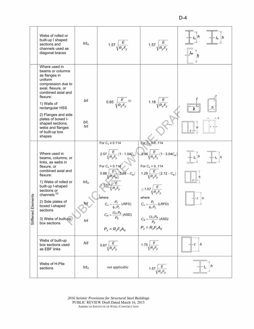
PUBLIC R
EVIEW
ONE D
RAFT
D-4
2016 Seismic Provisions for Structural Steel Buildings PUBLIC REVIEW Draft Dated March 16, 2015
AMERICAN INSTITUTE OF STEEL CONSTRUCTION
Webs of rolled or built-up I shaped sections and channels used as diagonal braces
h/tw
1.57y y
ER F
1.57y y
ER F
Where used in beams or columns as flanges in uniform compression due to axial, flexure, or combined axial and flexure:
1) Walls of rectangular HSS
2) Flanges and side plates of boxed I-shaped sections, webs and flanges of built-up box shapes
b/t
b/t, h/t
0.65 y y
ER F
[b] 1.18y y
ER F
Stif
fene
d E
lem
ents
Where used in beams, columns, or links, as webs in flexure, or combined axial and flexure:
1) Webs of rolled or built-up I-shaped sections or channels [c]
2) Side plates of boxed I-shaped sections 3) Webs of built-up box sections
h/tw
h/t
h/t
For Ca ≤ 0.114
( )2.57 1 1.04 ay y
E CR F
-
For Ca > 0.114
( )0.88 2.68 ay y
E CR F
-
y y
ER F
1.57³
where
ua
c y
PCP
LRFD)
c a
ay
PCP
(ASD)
Py = RyFyAg
For Ca ≤ 0..114
( )3.96 1 3.04 ay y
E CR F
-
For Ca > 0..114
( )1.29 2.12 ay y
E CR F
-
y y
ER F
1.57³
where
ua
c y
PCP
(LRFD)
c aa
y
PCP
(ASD)
Py = RyFyAg
Webs of built-up box sections used as EBF links
h/t
y y
ER F
0.67
y y
ER F
1.75
Webs of H-Pile sections h/tw not applicable
y y
ER F
1.57

PUBLIC R
EVIEW
ONE D
RAFT
D-5
2016 Seismic Provisions for Structural Steel Buildings PUBLIC REVIEW Draft Dated March 16, 2015
AMERICAN INSTITUTE OF STEEL CONSTRUCTION
Walls of round HSS D/t .y y
ER F
0 053 .y y
ER F
0 062 [d] C
ompo
site
Ele
men
ts
Walls of rectangular filled composite members
b/t
y y
ER F
1.48 y y
ER F
2.37
Walls of round filled composite members
D/t .y y
ER F
0 085 .y y
ER F
0 17
[a] For tee shaped compression members, the limiting width-to-thickness ratio for highly ductile members for the
stem of the tee shall be y y
ER F
0.40 where either of the following conditions are satisfied:
(1) Buckling of the compression member occurs about the plane of the stem. (2) The axial compression load is transferred at end connections to only the outside face of the flange of
the tee resulting in an eccentric connection that reduces the compression stresses at the tip of the stem.
[b] The limiting width-to-thickness ratio of flanges of boxed I-shaped sections and built-up box sections of
columns in SMF systems shall not exceed y y
ER F
0.63 .
[c] For I-shaped beams in SMF systems, where Ca is less than or equal to 0.114, the limiting ratio h/tw shall
not exceedy y
ER F
2.57 . For I-shaped beams in IMF systems, where Ca is less than or equal to 0.114, the
limiting width-to-thickness ratio shall not exceed y y
ER F
3.95
[d] The limiting diameter-to-thickness ratio of round HSS members used as beams or columns shall not
exceed y y
ER F
0.077
D1.2. Stability Bracing of Beams 1558
When required in Chapters E, F, G and H, stability bracing shall be 1559 provided as required in this section to restrain lateral-torsional buckling 1560 of structural steel or concrete-encased beams subject to flexure and 1561 designated as moderately ductile members or highly ductile members. 1562
User Note: In addition to the requirements in Chapters E, F, G and H to 1563 provide stability bracing for various beam members such as intermediate 1564 and special moment frame beams, stability bracing is also required for 1565 columns in the special cantilever column system (SCCS) in Section E6. 1566
D1.2a. Moderately Ductile Members 1567
1. The bracing of moderately ductile steel beams shall satisfy the 1568 following requirements: 1569

PUBLIC R
EVIEW
ONE D
RAFT
D-6
2016 Seismic Provisions for Structural Steel Buildings PUBLIC REVIEW Draft Dated March 16, 2015
AMERICAN INSTITUTE OF STEEL CONSTRUCTION
(a) Both flanges of beams shall be laterally braced or the 1570 beam cross section shall be braced with torsional point 1571 bracing. 1572
(b) Beam bracing shall meet the requirements of Appendix 6 1573 of the Specification for lateral or torsional bracing of 1574 beams, where the required flexural strength of the 1575 member shall be: 1576
r y y sM R F Z (D1-1) 1577
where 1578 Cd = 1.0 1579 Ry = ratio of the expected yield stress to the 1580
specified minimum yield stress 1581 Z = plastic section modulus about the axis of 1582
bending, in.3 (mm3) 1583 αs = LRFD-ASD force level adjustment factor 1584 = 1.0 for LRFD and 1.5 for ASD 1585
(c) Beam bracing shall have a maximum spacing of 1586
Lb =0.19ryE/(RyFy) (D1-2) 1587
2. The bracing of moderately ductile concrete-encased composite 1588 beams shall satisfy the following requirements: 1589
(a) Both flanges of members shall be laterally braced or the 1590 beam cross section shall be braced with torsional point 1591 bracing. 1592
(b) Lateral bracing shall meet the requirements of Appendix 1593 6 of the Specification for lateral or torsional bracing of 1594 beams, where Mr = Mp,exp of the beam as specified in 1595 Section G2.6d, and Cd = 1.0. 1596
(c) Member bracing shall have a maximum spacing of 1597
Lb = 0.19ryE/(RyFy) (D1-3) 1598
using the material properties of the steel section and ry in 1599 the plane of buckling calculated based on the elastic 1600 transformed section. 1601
D1.2b. Highly Ductile Members 1602
In addition to the requirements of Sections D1.2a.1(a) and (b), and 1603 D1.2a.2(a) and (b), the bracing of highly ductile beam members shall 1604 have a maximum spacing of Lb =0.095ryE/(RyFy). For concrete-encased 1605 composite beams, the material properties of the steel section shall be used 1606

PUBLIC R
EVIEW
ONE D
RAFT
D-7
2016 Seismic Provisions for Structural Steel Buildings PUBLIC REVIEW Draft Dated March 16, 2015
AMERICAN INSTITUTE OF STEEL CONSTRUCTION
and the calculation for ry in the plane of buckling shall be based on the 1607 elastic transformed section. 1608
D1.2c. Special Bracing at Plastic Hinge Locations 1609
Special bracing shall be located adjacent to expected plastic hinge 1610 locations where required by Chapters E, F, G or H. 1611
(1) For structural steel beams, such bracing shall satisfy the following 1612 requirements: 1613
(a) Both flanges of beams shall be laterally braced or the 1614 member cross section shall be braced with torsional point 1615 bracing. 1616
(b) The required strength of lateral bracing of each flange 1617 provided adjacent to plastic hinges shall be: 1618
0.06r y y s oP R F Z h (D1-4) 1619
where 1620
ho = distance between flange centroids, in. (mm) 1621
The required strength of torsional bracing provided 1622 adjacent to plastic hinges shall be: 1623
0.06r y y sM R F Z (D1-5) 1624
(c) The required bracing stiffness shall satisfy the 1625 requirements of Appendix 6 of the Specification for 1626 lateral or torsional bracing of beams with Cd =1.0 and 1627 where the required flexural strength of the beam shall be 1628 taken as: 1629
r y y sM R F Z (D1-6) 1630
(2) For concrete-encased composite beams, such bracing shall satisfy 1631 the following requirements: 1632
(a) Both flanges of beams shall be laterally braced or the 1633 beam cross section shall be braced with torsional point 1634 bracing. 1635
(b) The required strength of lateral bracing provided adjacent 1636 to plastic hinges shall be 1637
Pu = 0.06Mp,exp /ho (D1-7) 1638
of the beam, where 1639

PUBLIC R
EVIEW
ONE D
RAFT
D-8
2016 Seismic Provisions for Structural Steel Buildings PUBLIC REVIEW Draft Dated March 16, 2015
AMERICAN INSTITUTE OF STEEL CONSTRUCTION
Mp,exp = expected flexural strength of the steel, 1640 concrete-encased or composite beam, kip-1641 in. (N-mm); determined in accordance with 1642 Section G2.6d. 1643
The required strength for torsional bracing provided 1644 adjacent to plastic hinges shall be Mu = 0.06Mp,exp of the 1645 beam. 1646
(c) The required bracing stiffness shall satisfy the 1647 requirements of Appendix 6 of the Specification for 1648 lateral or torsional bracing of beams where Mr = Mu = 1649 Mp,exp of the beam is determined in accordance with 1650 Section G2.6d, and Cd = 1.0. 1651
D1.3. Protected Zones 1652
Discontinuities specified in Section I2.1 resulting from fabrication and 1653 erection procedures and from other attachments are prohibited in the area 1654 of a member or a connection element designated as a protected zone by 1655 these Provisions or ANSI/AISC 358. 1656
Exception: Welded steel headed stud anchors and other connections are 1657 permitted in protected zones when designated in ANSI/AISC 358, or as 1658 otherwise determined with a connection prequalification in accordance 1659 with Section K1, or as determined in a program of qualification testing in 1660 accordance with Sections K2 and K3. 1661
D1.4. Columns 1662
Columns in moment frames, braced frames and shear walls shall satisfy 1663 the requirements of this section. 1664
D1.4a. Required Strength 1665
The required strength of columns in the SFRS shall be determined from 1666 the greater effect of the following: 1667
1668 (a) The load effect resulting from the analysis requirements for the 1669
applicable system per Sections E, F, G and H. 1670 1671 (b) The compressive axial strength and tensile strength as determined 1672
using the overstrength seismic load. It is permitted to neglect 1673 applied moments in this determination unless the moment results 1674 from a load applied to the column between points of lateral 1675 support. 1676
1677 1678

PUBLIC R
EVIEW
ONE D
RAFT
D-9
2016 Seismic Provisions for Structural Steel Buildings PUBLIC REVIEW Draft Dated March 16, 2015
AMERICAN INSTITUTE OF STEEL CONSTRUCTION
For columns that are common to intersecting frames, determination of the 1679 required axial strength, including the overstrength seismic load or the 1680 capacity-limited seismic load, as applicable, shall consider the potential 1681 for simultaneous inelasticity from all such frames. The direction of 1682 application of the load in each such frame shall be selected to produce the 1683 most severe load effect on the column. 1684
Exceptions: 1685
(a) It is permitted to limit the required axial strength for such 1686 columns based on a three-dimensional nonlinear analysis in 1687 which ground motion is simultaneously applied in two orthogonal 1688 directions, in accordance with Section C3. 1689
(b) Columns that are part of Sections E1, F1, G1, H1, H4 or 1690 combinations thereof need not be designed for these loads. 1691
D1.4b. Encased Composite Columns 1692
Encased composite columns shall satisfy the requirements of 1693 Specification Chapter I, in addition to the requirements of this section. 1694 Additional requirements, as specified for moderately ductile members 1695 and highly ductile members in Sections D1.4b.1 and 2, shall apply as 1696 required in the descriptions of the composite seismic systems in Chapters 1697 G and H. 1698
1. Moderately Ductile Members 1699
Encased composite columns used as moderately ductile members shall 1700 satisfy the following requirements: 1701
(1) The maximum spacing of transverse reinforcement at the 1702 top and bottom shall be the least of the following: 1703
(i) one-half the least dimension of the section 1704
(ii) 8 longitudinal bar diameters 1705
(iii) 24 tie bar diameters 1706
(iv) 12 in. (300 mm) 1707
(2) This spacing shall be maintained over a vertical distance 1708 equal to the greatest of the following lengths, measured 1709 from each joint face and on both sides of any section 1710 where flexural yielding is expected to occur: 1711
(i) one-sixth the vertical clear height of the column 1712
(ii) the maximum cross-sectional dimension 1713

PUBLIC R
EVIEW
ONE D
RAFT
D-10
2016 Seismic Provisions for Structural Steel Buildings PUBLIC REVIEW Draft Dated March 16, 2015
AMERICAN INSTITUTE OF STEEL CONSTRUCTION
(iii) 18 in. (450 mm) 1714
(3) Tie spacing over the remaining column length shall not 1715 exceed twice the spacing defined in Section D1.4b.1(1). 1716
(4) Splices and end bearing details for encased composite 1717 columns in composite ordinary SFRS of Sections G1, H1 1718 and H4 shall satisfy the requirements of the Specification 1719 and ACI 318 Section 10.7. The design shall comply with 1720 ACI 318 Sections 18.2.7 and 18.2.8. The design shall 1721 consider any adverse behavioral effects due to abrupt 1722 changes in either the member stiffness or the nominal 1723 tensile strength. Transitions to reinforced concrete 1724 sections without embedded structural steel members, 1725 transitions to bare structural steel sections, and column 1726 bases shall be considered abrupt changes. 1727
(5) Welded wire fabric shall be prohibited as transverse 1728 reinforcement. 1729
2. Highly Ductile Members 1730
Encased composite columns used as highly ductile members shall 1731 satisfy Section D1.4b.1 in addition to the following requirements: 1732
(1) Longitudinal load-carrying reinforcement shall satisfy the 1733 requirements of ACI 318 Section 18.7.4. 1734
(2) Transverse reinforcement shall be hoop reinforcement as 1735 defined in ACI 318 Chapter 18 and shall satisfy the 1736 following requirements: 1737
(i) The minimum area of tie reinforcement, Ash, shall 1738 be: 1739
0.09 1 y s csh cc
n ysr
F A fA h sP F
(D1-8) 1740
where 1741 As = cross-sectional area of the 1742
structural steel core, in.2 (mm2) 1743 Fy = specified minimum yield stress of 1744
the structural steel core, ksi (MPa) 1745 Fysr = specified minimum yield stress of 1746
the ties, ksi (MPa) 1747 Pn = nominal compressive strength of 1748
the composite column calculated 1749 in accordance with the 1750 Specification, kips (N) 1751

PUBLIC R
EVIEW
ONE D
RAFT
D-11
2016 Seismic Provisions for Structural Steel Buildings PUBLIC REVIEW Draft Dated March 16, 2015
AMERICAN INSTITUTE OF STEEL CONSTRUCTION
hcc = cross-sectional dimension of the 1752 confined core measured center-to-1753 center of the tie reinforcement, in. 1754 (mm) 1755
fc = specified compressive strength of 1756 concrete, ksi (MPa) 1757
s = spacing of transverse 1758 reinforcement measured along the 1759 longitudinal axis of the structural 1760 member, in. (mm) 1761
Equation D1-8 need not be satisfied if the nominal 1762 strength of the concrete-encased structural steel 1763 section alone is greater than the load effect from a 1764 load combination of 1.0D+0.5L, 1765 1766 where 1767
D = dead load due to the weight of the 1768 structural elements and permanent 1769 features on the building, kips (N) 1770
L = live load due to occupancy and 1771 moveable equipment, kips (N) 1772
(ii) The maximum spacing of transverse 1773 reinforcement along the length of the column shall 1774 be the lesser of six longitudinal load-carrying bar 1775 diameters or 6 in. (150 mm). 1776
(iii) Where transverse reinforcement is specified in 1777 Sections D1.4b.2(3), D1.4b.2(4), or D1.4b.2(5), 1778 the maximum of transverse reinforcement along 1779 the member length shall be the lesser of one-1780 fourth the least member dimension or 4 in. (100 1781 mm).” Confining reinforcement shall be spaced 1782 not more than 14 in. (350 mm) on center in the 1783 transverse direction. 1784
1785 (3) Encased composite columns in braced frames with 1786
required compressive strengths, not including the 1787 overstrength seismic load, greater than 0.2Pn shall have 1788 transverse reinforcement as specified in Section 1789 D1.4b.2(2)(iii) over the total element length. This 1790 requirement need not be satisfied if the nominal strength 1791 of the concrete-encased steel section alone is greater than 1792 the load effect from a load combination of 1.0D+0.5L. 1793
1794 (4) Composite columns supporting reactions from 1795
discontinued stiff members, such as walls or braced 1796

PUBLIC R
EVIEW
ONE D
RAFT
D-12
2016 Seismic Provisions for Structural Steel Buildings PUBLIC REVIEW Draft Dated March 16, 2015
AMERICAN INSTITUTE OF STEEL CONSTRUCTION
frames, shall have transverse reinforcement as specified in 1797 Section D1.4b.2(2)(iii) over the full length beneath the 1798 level at which the discontinuity occurs if the required 1799 compressive strength, not including the overstrength 1800 seismic load, exceeds 0.1Pn. Transverse reinforcement 1801 shall extend into the discontinued member for at least the 1802 length required to develop full yielding in the concrete-1803 encased steel section and longitudinal reinforcement. This 1804 requirement need not be satisfied if the nominal strength 1805 of the concrete-encased steel section alone is greater than 1806 the load effect from a load combination of 1.0D+0.5L. 1807
1808 (5) Encased composite columns used in a C-SMF shall 1809
satisfy the following requirements: 1810 1811
(i) Transverse reinforcement shall satisfy the 1812 requirements in Section D1.4b.2(2) at the top and 1813 bottom of the column over the region specified in 1814 Section D1.4b.1(2). 1815
1816 (ii) The strong-column/weak-beam design 1817
requirements in Section G3.4a shall be satisfied. 1818 Column bases shall be detailed to sustain inelastic 1819 flexural hinging. 1820
1821 (iii) The required shear strength of the column shall 1822
satisfy the requirements of ACI 318 Section 1823 18.7.6.1. 1824
1825 (6) When the column terminates on a footing or mat 1826
foundation, the transverse reinforcement as specified in 1827 this section shall extend into the footing or mat at least 12 1828 in. (300 mm). When the column terminates on a wall, the 1829 transverse reinforcement shall extend into the wall for at 1830 least the length required to develop full yielding in the 1831 concrete-encased shape and longitudinal reinforcement. 1832
D1.4c. Filled Composite Columns 1833
This section applies to columns that meet the limitations of Specification 1834 Section I2.2. Such columns shall be designed to satisfy the requirements 1835 of Specification Chapter I, except that the nominal shear strength of the 1836 composite column shall be the nominal shear strength of the structural 1837 steel section alone, based on its effective shear area. 1838
D1.5. Composite Slab Diaphragms 1839 1840

PUBLIC R
EVIEW
ONE D
RAFT
D-13
2016 Seismic Provisions for Structural Steel Buildings PUBLIC REVIEW Draft Dated March 16, 2015
AMERICAN INSTITUTE OF STEEL CONSTRUCTION
The design of composite floor and roof slab diaphragms for seismic 1841 effects shall meet the following requirements. 1842
D1.5a. Load Transfer 1843
Details shall be provided to transfer loads between the diaphragm and 1844 boundary members, collector elements, and elements of the horizontal 1845 framing system. 1846
D1.5b. Nominal Shear Strength 1847
The nominal in-plane shear strength of composite diaphragms and 1848 concrete slab on steel deck diaphragms shall be taken as the nominal 1849 shear strength of the reinforced concrete above the top of the steel deck 1850 ribs in accordance with ACI 318 excluding Chapter 14. Alternatively, the 1851 composite diaphragm nominal shear strength shall be determined by in-1852 plane shear tests of concrete-filled diaphragms. 1853
D1.6. BUILT-UP STRUCTURAL STEEL MEMBERS 1854
This section addresses connections between components of built-up 1855 members where specific requirements are not provided in the system 1856 chapters of these Provisions or in ANSI/AISC 358. 1857 1858 Connections between components of built-up members subject to 1859 inelastic behavior shall be designed for the expected forces arising from 1860 that inelastic behavior. 1861 1862 Connections between components of built-up members where inelastic 1863 behavior is not expected shall be designed for the load effect including 1864 the overstrength seismic forces. 1865 1866 Where connections between elements of a built-up member are required 1867 in a protected zone, they shall develop the strength of the weaker 1868 connecting element. 1869
Built-up members may be used in connections requiring testing per the 1870 Provisions provided they are accepted by ANSI/AISC 358 for use in a 1871 prequalified joint or have been verified in a qualification test. 1872

PUBLIC R
EVIEW
ONE D
RAFT
D-14
2016 Seismic Provisions for Structural Steel Buildings PUBLIC REVIEW Draft Dated March 16, 2015
AMERICAN INSTITUTE OF STEEL CONSTRUCTION
D2. CONNECTIONS 1873
D2.1. General 1874
Connections, joints and fasteners that are part of the SFRS shall comply 1875 with Specification Chapter J, and with the additional requirements of this 1876 section. 1877
Splices and bases of columns that are not designated as part of the SFRS 1878 shall satisfy the requirements of Sections D2.5a, D2.5c and D2.6. 1879
Where protected zones are designated in connection elements by these 1880 Provisions or ANSI/AISC 358, they shall satisfy the requirements of 1881 Sections D1.3 and I2.1. 1882
D2.2. Bolted Joints 1883
Bolted joints shall satisfy the following requirements: 1884
(a) The available shear strength of bolted joints using standard holes 1885 or short slotted holes perpendicular to the applied load shall be 1886 calculated as that for bearing-type joints in accordance with 1887 Specification Sections J3.6 and J3.10. The nominal bolt bearing 1888 and tearout equations per Section J3.10 of the Specification where 1889 deformation at the bolt hole at service load is a design 1890 consideration shall be used. 1891
Exception: Where the required strength of a connection is based 1892 upon the expected strength of a member or element, it is 1893 permitted to use the bolt bearing and tearout equations in 1894 accordance with Specification Section J3.10 where deformation is 1895 not a design consideration. 1896
(b) Bolts and welds shall not be designed to share force in a joint or 1897 the same force component in a connection. 1898
User Note: A member force, such as a diagonal brace axial force, 1899 must be resisted at the connection entirely by one type of joint (in 1900 other words, either entirely by bolts or entirely by welds). A 1901 connection in which bolts resist a force that is normal to the force 1902 resisted by welds, such as a moment connection in which welded 1903 flanges transmit flexure and a bolted web transmits shear, is not 1904 considered to be sharing the force. 1905
(c) Bolt holes shall be standard holes or short-slotted holes 1906 perpendicular to the applied load in bolted joints where the 1907 seismic load effects are transferred by shear in the bolts. 1908 Oversized holes, short-slotted holes, or long-slotted holes are 1909 permitted in connections where the seismic load effects are 1910 transferred by tension in the bolts but not by shear in the bolts. 1911

PUBLIC R
EVIEW
ONE D
RAFT
D-15
2016 Seismic Provisions for Structural Steel Buildings PUBLIC REVIEW Draft Dated March 16, 2015
AMERICAN INSTITUTE OF STEEL CONSTRUCTION
Where approved by the engineer of record, long-slotted holes are 1912 also permitted where the seismic load effects are transferred by 1913 shear when the slot is perpendicular to the applied load. 1914
Exception: 1915
(1) For diagonal braces, oversized holes are permitted in one 1916 connection ply only when the connection is designed as a 1917 slip-critical joint. 1918
(2) Alternative hole types are permitted if designated in 1919 ANSI/AISC 358, or if otherwise determined in a connection 1920 prequalification in accordance with Section K1, or if 1921 determined in a program of qualification testing in accordance 1922 with Section K2 or Section K3. 1923
User Note: Diagonal brace connections with oversized holes 1924 must also satisfy other limit states including bolt bearing and bolt 1925 shear for the required strength of the connection as defined in 1926 Sections F1, F2, F3 and F4. 1927
(d) All bolts shall be installed as pretensioned high-strength bolts. 1928 Faying surfaces shall satisfy the requirements for slip-critical 1929 connections in accordance with Specification Section J3.8 with a 1930 faying surface with a Class A slip coefficient or higher. 1931
1932 Exceptions: Connection surfaces are permitted to have coatings 1933
with a slip coefficient less than that of a Class A faying surface 1934 for the following: 1935
1936 (1) End plate moment connections conforming to the 1937
requirements of Section E1, or ANSI/AISC 358 1938 1939 (2) Bolted joints where the seismic load effects are 1940
transferred either by tension in bolts or by compression 1941 bearing but not by shear in bolts 1942
1943
D2.3. Welded Joints 1944
There are no additional welding requirements. 1945
D2.4. Continuity Plates and Stiffeners 1946
The design of continuity plates and stiffeners located in the webs of 1947 rolled shapes shall allow for the reduced contact lengths to the member 1948 flanges and web based on the corner clip sizes in Section I2.4. 1949
D2.5. Column Splices 1950

PUBLIC R
EVIEW
ONE D
RAFT
D-16
2016 Seismic Provisions for Structural Steel Buildings PUBLIC REVIEW Draft Dated March 16, 2015
AMERICAN INSTITUTE OF STEEL CONSTRUCTION
D2.5a. Location of Splices 1951
For all building columns, including those not designated as part of the 1952 SFRS, column splices shall be located 4 ft (1.2 m) or more away from the 1953 beam-to-column flange connections. 1954
Exceptions: 1955
(a) When the column clear height between beam-to-column flange 1956 connections is less than 8 ft (2.4 m), splices shall be at half the 1957 clear height 1958
(b) Column splices with webs and flanges joined by complete-joint-1959 penetration groove welds are permitted to be located closer to the 1960 beam-to-column flange connections, but not less than the depth of 1961 the column 1962
(c) Splices in composite columns 1963
User Note: Where possible, splices should be located at least 4 ft (1.2 m) 1964 above the finished floor elevation to permit installation of perimeter 1965 safety cables prior to erection of the next tier and to improve 1966 accessibility. 1967
D2.5b. Required Strength 1968
The required strength of column splices in the SFRS shall be the greater 1969 of: 1970
(a) The required strength of the columns, including that determined 1971 from Chapters E, F, G and H and Section D1.4a; or, 1972
(b) The required strength determined using the overstrength seismic 1973 load. 1974
In addition, welded column splices in which any portion of the column is 1975 subject to a calculated net tensile load effect determined using the 1976 overstrength seismic load shall satisfy all of the following requirements: 1977
(a) The available strength of partial-joint-penetration (PJP) groove 1978 welded joints, if used, shall be at least equal to 200% of the 1979 required strength. Exception: Partial-joint penetration (PJP) 1980 groove welds are excluded from this requirement according to the 1981 exceptions to Sections E2.6g, E3.6g and E4.6c. 1982
(b) The available strength for each flange splice shall be at least 1983 equal to0.5 y y f f sR F b t , where RyFy is the expected yield stress 1984
of the column material and bftf is the area of one flange of the 1985 smaller column connected. 1986

PUBLIC R
EVIEW
ONE D
RAFT
D-17
2016 Seismic Provisions for Structural Steel Buildings PUBLIC REVIEW Draft Dated March 16, 2015
AMERICAN INSTITUTE OF STEEL CONSTRUCTION
(c) Where butt joints in column splices are made with complete-1987 joint-penetration groove welds, when tension stress at any 1988 location in the smaller flange exceeds 0.30 y sF tapered 1989
transitions are required between flanges of unequal thickness or 1990 width. Such transitions shall be in accordance with AWS 1991 D1.8/D1.8M clause 4.2. 1992
D2.5c. Required Shear Strength 1993
For all building columns including those not designated as part of the 1994 SFRS, the required shear strength of column splices with respect to both 1995 orthogonal axes of the column shall be pc sM H , where Mpc is the 1996
lesser plastic flexural strength of the column sections for the direction in 1997 question, and H is the height of the story, which is permitted to be taken 1998 as the distance between the centerline of floor framing at each of the 1999 levels above and below, or the distance between the top of floor slabs at 2000 each of the levels above and below. 2001
The required shear strength of splices of columns in the SFRS shall be 2002 the greater of the above requirement or the required shear strength 2003 determined per Section D2.5b(a) and (b). 2004
D2.5d. Structural Steel Splice Configurations 2005
Structural steel column splices are permitted to be either bolted or 2006 welded, or welded to one column and bolted to the other. Splice 2007 configurations shall meet all specific requirements in Chapters E, F, G or 2008 H. 2009
Splice plates or channels used for making web splices in SFRS columns 2010 shall be placed on both sides of the column web. 2011
For welded butt joint splices made with groove welds, weld tabs shall be 2012 removed in accordance with AWS D1.8/D1.8M clause 6.11. Steel 2013 backing of groove welds need not be removed. 2014
D2.5e. Splices in Encased Composite Columns 2015
For encased composite columns, column splices shall conform to Section 2016 D1.4b and ACI 318 Section 18.7.4.3. 2017
D2.6. Column Bases 2018
The required strength of column bases, including those that are not 2019 designated as part of the SFRS, shall be calculated in accordance with 2020 this section. 2021
The available strength of steel elements at the column base, including 2022 base plates, anchor rods, stiffening plates, and shear lug elements shall be 2023 in accordance with the Specification. 2024

PUBLIC R
EVIEW
ONE D
RAFT
D-18
2016 Seismic Provisions for Structural Steel Buildings PUBLIC REVIEW Draft Dated March 16, 2015
AMERICAN INSTITUTE OF STEEL CONSTRUCTION
Where columns are welded to base plates with groove welds, weld tabs 2025 and weld backing shall be removed, except that weld backing located on 2026 the inside of flanges and weld backing on the web of I-shaped sections 2027 need not be removed if backing is attached to the column base plate with 2028 a continuous c-in. fillet weld. Fillet welds of backing to the inside of 2029 column flanges are prohibited. 2030
The available strength of concrete elements and reinforcing steel at the 2031 column base shall be in accordance with ACI 318. When the design of 2032 anchor rods assumes that the ductility demand is provided for by 2033 deformations in the anchor rods and anchorage into reinforced concrete, 2034 the design shall meet the requirements of ACI 318 Chapter 17. 2035 Alternatively, when the ductility demand is provided for elsewhere, the 2036 anchor rods and anchorage into reinforced concrete are permitted to be 2037 designed for the maximum loads resulting from the deformations 2038 occurring elsewhere including the effects of material overstrength and 2039 strain hardening. 2040
User Note: When using concrete reinforcing steel as part of the 2041 anchorage embedment design, it is important to consider the anchor 2042 failure modes and provide reinforcement that is developed on both sides 2043 of the expected failure surface. See ACI 318 Chapter 17, including 2044 Commentary. 2045
D2.6a. Required Axial Strength 2046
The required axial strength of column bases that are designated as part of 2047 the SFRS, including their attachment to the foundation, shall be the 2048 summation of the vertical components of the required connection 2049 strengths of the steel elements that are connected to the column base, but 2050 not less than the greater of: 2051
(a) The column axial load calculated using the overstrength seismic 2052 load 2053
(b) The required axial strength for column splices, as prescribed in 2054 Section D2.5 2055
User Note: The vertical components can include both the axial load 2056 from columns and the vertical component of the axial load from diagonal 2057 members framing into the column base. Section D2.5 includes references 2058 to Section D1.4a and Chapters E, F, G and H. Where diagonal braces 2059 frame to both sides of a column, the effects of compression brace 2060 buckling should be considered in the summation of vertical components. 2061 See Section F2.3. 2062
D2.6b. Required Shear Strength 2063
The required shear strength of column bases, including those not 2064 designated as part of the SFRS, and their attachments to the foundations, 2065

PUBLIC R
EVIEW
ONE D
RAFT
D-19
2016 Seismic Provisions for Structural Steel Buildings PUBLIC REVIEW Draft Dated March 16, 2015
AMERICAN INSTITUTE OF STEEL CONSTRUCTION
shall be the summation of the horizontal component of the required 2066 connection strengths of the steel elements that are connected to the 2067 column base as follows: 2068
(a) For diagonal braces, the horizontal component shall be 2069 determined from the required strength of diagonal brace 2070 connections for the SFRS. 2071
(b) For columns, the horizontal component shall be equal to the 2072 lesser of the following: 2073
(i) 2RyFyZ/(αsH) of the column 2074
(ii) The shear calculated using the overstrength seismic load. 2075
(c) The summation of the required strengths of the horizontal 2076 components shall not be less than 0.7FyZ/(αsH) of the column. 2077
Exceptions: 2078
(a) Single story columns with simple connections at both ends need 2079 not comply with Section D2.6b(b) or D2.6b(c). 2080
(b) The minimum required shear strength per Section D2.6b(c) need 2081 not exceed the maximum load effect that can be transferred from 2082 the column to the foundation as determined by either a nonlinear 2083 analysis per Section C3, or an analysis that includes the effects of 2084 inelastic behavior resulting in 0.025H story drift at either the first 2085 or second story, but not both concurrently. 2086
User Note: The horizontal components can include the shear load from 2087 columns and the horizontal component of the axial load from diagonal 2088 members framing into the column base. Horizontal forces for columns 2089 that are not part of the SFRS system can be determined from Section 2090 D2.6b(c) as Section D2.6b(b) will typically not govern. 2091
D2.6c. Required Flexural Strength 2092
Where column bases are designed as moment connections to the 2093 foundation, the required flexural strength of column bases that are 2094 designated as part of the SFRS, including their attachment to the 2095 foundation, shall be the summation of the required connection strengths 2096 of the steel elements that are connected to the column base as follows: 2097
(a) For diagonal braces, the required flexural strength shall be at least 2098 equal to the required flexural strength of diagonal brace 2099 connections. 2100
(b) For columns, the required flexural strength shall be at least equal 2101 to the lesser of the following: 2102

PUBLIC R
EVIEW
ONE D
RAFT
D-20
2016 Seismic Provisions for Structural Steel Buildings PUBLIC REVIEW Draft Dated March 16, 2015
AMERICAN INSTITUTE OF STEEL CONSTRUCTION
(1) 1.1 y y sR F Z of the column, or 2103
(2) the moment calculated using the overstrength seismic 2104 load, provided that a ductile limit state in either the 2105 column base or the foundation controls the design. 2106
User Note: Moments at column to column base connections designed as 2107 simple connections may be ignored. 2108
D2.7. Composite Connections 2109
This section applies to connections in buildings that utilize composite 2110 steel and concrete systems wherein seismic load is transferred between 2111 structural steel and reinforced concrete components. Methods for 2112 calculating the connection strength shall satisfy the requirements in this 2113 section. Unless the connection strength is determined by analysis or 2114 testing, the models used for design of connections shall satisfy the 2115 following requirements: 2116
(a) Force shall be transferred between structural steel and 2117 reinforced concrete through: 2118
(1) direct bearing from internal bearing mechanisms; 2119
(2) shear connection; 2120
(3) shear friction with the necessary clamping force 2121 provided by reinforcement normal to the plane of shear 2122 transfer; or 2123
(4) a combination of these means. 2124
The contribution of different mechanisms is permitted to be 2125 combined only if the stiffness and deformation capacity of the 2126 mechanisms are compatible. Any potential bond strength 2127 between structural steel and reinforced concrete shall be ignored 2128 for the purpose of the connection force transfer mechanism. 2129
(b) The nominal bearing and shear-friction strengths shall meet the 2130 requirements of ACI 318 Chapter 16. Unless a higher strength is 2131 substantiated by cyclic testing, the nominal bearing and shear-2132 friction strengths shall be reduced by 25% for the composite 2133 seismic systems described in Sections G3, H2, H3, H5 and H6. 2134
(c) Face bearing plates consisting of stiffeners between the flanges of 2135 steel beams shall be provided when beams are embedded in 2136

PUBLIC R
EVIEW
ONE D
RAFT
D-21
2016 Seismic Provisions for Structural Steel Buildings PUBLIC REVIEW Draft Dated March 16, 2015
AMERICAN INSTITUTE OF STEEL CONSTRUCTION
reinforced concrete columns or walls. 2137
(d) The nominal shear strength of concrete-encased steel panel zones 2138 in beam-to-column connections shall be calculated as the sum of 2139 the nominal strengths of the structural steel and confined 2140 reinforced concrete shear elements as determined in Section 2141 E3.6e and ACI 318 Section 18.8, respectively. 2142
(e) Reinforcement shall be provided to resist all tensile forces in 2143 reinforced concrete components of the connections. Additionally, 2144 the concrete shall be confined with transverse reinforcement. All 2145 reinforcement shall be fully developed in tension or compression, 2146 as applicable, beyond the point at which it is no longer required to 2147 resist the forces. Development lengths shall be determined in 2148 accordance with ACI 318 Chapter 25. Additionally, development 2149 lengths for the systems described in Sections G3, H2, H3, H5 and 2150 H6 shall satisfy the requirements of ACI 318 Section 18.8.5 2151
(f) Composite connections shall satisfy the following additional 2152 requirements: 2153
(1) When the slab transfers horizontal diaphragm forces, the 2154 slab reinforcement shall be designed and anchored to 2155 carry the in-plane tensile forces at all critical sections in 2156 the slab, including connections to collector beams, 2157 columns, diagonal braces and walls. 2158
(2) For connections between structural steel or composite 2159 beams and reinforced concrete or encased composite 2160 columns, transverse hoop reinforcement shall be provided 2161 in the connection region of the column to satisfy the 2162 requirements of ACI 318 Section 18.8, except for the 2163 following modifications: 2164
(i) Structural steel sections framing into the 2165 connections are considered to provide 2166 confinement over a width equal to that of face 2167 bearing plates welded to the beams between the 2168 flanges. 2169
(ii) Lap splices are permitted for perimeter ties when 2170 confinement of the splice is provided by face 2171 bearing plates or other means that prevents 2172 spalling of the concrete cover in the systems 2173 described in Sections G1, G2, H1 and H4. 2174
(iii) The longitudinal bar sizes and layout in reinforced 2175 concrete and composite columns shall be detailed 2176 to minimize slippage of the bars through the 2177

PUBLIC R
EVIEW
ONE D
RAFT
D-22
2016 Seismic Provisions for Structural Steel Buildings PUBLIC REVIEW Draft Dated March 16, 2015
AMERICAN INSTITUTE OF STEEL CONSTRUCTION
beam-to-column connection due to high force 2178 transfer associated with the change in column 2179 moments over the height of the connection. 2180
User Note: The commentary provides guidance for determining panel 2181 zone shear strength. 2182
D2.8. Steel Anchors 2183
Where steel headed stud anchors or welded reinforcing bar anchors are 2184 part of the intermediate or special SFRS of Sections G2, G3, G4, H2, H3, 2185 H5 and H6, their shear and tensile strength shall be reduced by 25% 2186 from the specified strengths given in Specification Chapter I. 2187 2188 User Note: The 25% reduction is not necessary for gravity and collector 2189 components in structures with intermediate or special seismic force-2190 resisting systems designed for the overstrength seismic load. 2191
D3. DEFORMATION COMPATIBILITY OF NON-SFRS MEMBERS 2192 AND CONNECTIONS 2193
Where deformation compatibility of members and connections that are 2194 not part of the seismic force-resisting system (SFRS) is required by the 2195 applicable building code, these elements shall be designed to resist the 2196 combination of gravity load effects and the effects of deformations 2197 occurring at the design story drift calculated in accordance with the 2198 applicable building code. 2199
User Note: ASCE/SEI 7 stipulates the above requirement for both 2200 structural steel and composite members and connections. Flexible shear 2201 connections that allow member end rotations per Section J1.2 of the 2202 Specification should be considered to meet these requirements. Inelastic 2203 deformations are permitted in connections or members provided they are 2204 self-limiting and do not create instability in the member. See the 2205 Commentary for further discussion. 2206
D4. H-PILES 2207
D4.1. Design Requirements 2208
Design of H-piles shall comply with the requirements of the Specification 2209 regarding design of members subjected to combined loads. H-piles 2210 located in site classes E or F as defined by ASCE/SEI 7 shall satisfy the 2211 requirements for moderately ductile members of Section D1.1. 2212
D4.2. Battered H-Piles 2213
If battered (sloped) and vertical piles are used in a pile group, the vertical 2214 piles shall be designed to support the combined effects of the dead and 2215 live loads without the participation of the battered piles. 2216

PUBLIC R
EVIEW
ONE D
RAFT
D-23
2016 Seismic Provisions for Structural Steel Buildings PUBLIC REVIEW Draft Dated March 16, 2015
AMERICAN INSTITUTE OF STEEL CONSTRUCTION
D4.3. Tension 2217
Tension in each pile shall be transferred to the pile cap by mechanical 2218 means such as shear keys, reinforcing bars, or studs welded to the 2219 embedded portion of the pile. 2220
D4.4. Protected Zone 2221 2222
At each pile, the length equal to the depth of the pile cross section located 2223 directly below the bottom of the pile cap shall be designated as a 2224 protected zone meeting the requirements of Sections D1.3 and I2.1. 2225
2226

PUBLIC R
EVIEW
ONE D
RAFT
E-1
2016 Seismic Provisions for Structural Steel Buildings PUBLIC REVIEW Draft dated March 16, 2015
AMERICAN INSTITUTE OF STEEL CONSTRUCTION
CHAPTER E 2300
MOMENT-FRAME SYSTEMS 2301
This chapter provides the basis of design, the requirements for analysis, and the 2302 requirements for the system, members and connections for steel moment-frame systems. 2303 The chapter is organized as follows: 2304
E1. Ordinary Moment Frames (OMF) 2305 E2. Intermediate Moment Frames (IMF) 2306 E3. Special Moment Frames (SMF) 2307 E4. Special Truss Moment Frames (STMF) 2308 E5. Ordinary Cantilever Column Systems (OCCS) 2309 E6. Special Cantilever Column Systems (SCCS) 2310
User Note: The requirements of this chapter are in addition to those required by the 2311 Specification and the applicable building code. 2312
E1. ORDINARY MOMENT FRAMES (OMF) 2313
E1.1. Scope 2314
Ordinary moment frames (OMF) of structural steel shall be designed in 2315 conformance with this section. 2316
E1.2. Basis of Design 2317
OMF designed in accordance with these provisions are expected to provide 2318 minimal inelastic deformation capacity in their members and connections. 2319
E1.3. Analysis 2320
There are no additional analysis requirements beyond those in Chapters A, B, C 2321 and D of these Provisions. 2322
E1.4. System Requirements 2323
There are no additional system requirements. 2324
E1.5. Members 2325
E1.5a. Basic Requirements 2326
There are no limitations on width-to-thickness ratios of members for OMF 2327 beyond those in the Specification. There are no requirements for stability bracing 2328 of beams or joints in OMF, beyond those in the Specification. Structural steel 2329 beams in OMF are permitted to be composite with a reinforced concrete slab to 2330 resist gravity loads. 2331
PUBLIC R
EVIEW
ONE D
RAFT
E-2
2016 Seismic Provisions for Structural Steel Buildings PUBLIC REVIEW Draft dated March 16, 2015
AMERICAN INSTITUTE OF STEEL CONSTRUCTION
E1.5b. Protected Zones 2332
There are no designated protected zones for OMF members. 2333
E1.6. Connections 2334
Beam-to-column connections are permitted to be fully restrained (FR) or partially 2335 restrained (PR) moment connections in accordance with this section. 2336
E1.6a. Demand Critical Welds 2337 2338
Complete-joint-penetration (CJP) groove welds of beam flanges to columns are 2339 demand critical welds, and shall satisfy the requirements of Section A3.4b and 2340 I2.3. 2341
E1.6b. FR Moment Connections 2342 2343
FR moment connections that are part of the seismic force-resisting system (SFRS) 2344 shall satisfy at least one of the following requirements: 2345
(a) FR moment connections shall be designed for a required flexural strength that 2346 is equal to the expected beam flexural strength, RyMp, times 1.1/αs, where αs = 2347 LRFD-ASD force level adjustment factor= 1.0 for LRFD and 1.5 for ASD. 2348
The required shear strength, Vu or Va, as applicable, of the connection shall be 2349 determined using the capacity-limited seismic load effect. The capacity-2350 limited horizontal seismic load effect, Ecl, shall be taken as: 2351
2 1.1cl y p cfE R M L (E1-1) 2352
where 2353 Lcf = clear length of beam, in. (mm) 2354 Mp = FyZ, kip-in. (N-mm) 2355 Ry = ratio of expected yield stress to the specified minimum yield stress, 2356
Fy 2357 2358
(b) FR moment connections shall be designed for a required flexural strength and 2359 a required shear strength equal to the maximum moment and corresponding 2360 shear that can be transferred to the connection by the system, including the 2361 effects of material overstrength and strain hardening. 2362
User Note: Factors that may limit the maximum moment and corresponding 2363 shear that can be transferred to the connection include: 2364
(1) the strength of the columns, and 2365
(2) the resistance of the foundations to uplift. 2366

PUBLIC R
EVIEW
ONE D
RAFT
E-3
2016 Seismic Provisions for Structural Steel Buildings PUBLIC REVIEW Draft dated March 16, 2015
AMERICAN INSTITUTE OF STEEL CONSTRUCTION
For options (a) and (b) in Section E1.6b, continuity plates shall be provided as 2367 required by Sections J10.1, J10.2 and J10.3 of the Specification. The bending 2368 moment used to check for continuity plates shall be the same bending moment 2369 used to design the beam-to-column connection; in other words, 1.1RyMp/αs or the 2370 maximum moment that can be transferred to the connection by the system. 2371
(c) FR moment connections between wide flange beams and the flange of wide 2372 flange columns shall either satisfy the requirements of Section E2.6 or E3.6, 2373 or shall satisfy the following requirements: 2374
(1) All welds at the beam-to-column connection shall satisfy the requirements 2375 of Chapter 3 of ANSI/AISC 358. 2376
(2) Beam flanges shall be connected to column flanges using complete-joint-2377 penetration groove welds. 2378
(3) The shape of weld access holes shall be in accordance with clause 6.10.1.2 2379 of AWS D1.8/D1.8M. Weld access hole quality requirements shall be in 2380 accordance with clause 6.10.2 of AWS D1.8/D1.8M. 2381
(4) Continuity plates shall satisfy the requirements of Section E3.6f. 2382
Exception: The welded joints of the continuity plates to the column 2383 flanges are permitted to be complete-joint-penetration groove welds, two-2384 sided partial-joint-penetration groove welds with contouring fillets, two-2385 sided fillet welds, or combinations of partial-joint-penetration groove 2386 welds and fillet welds. The required strength of these joints shall not be 2387 less than the available strength of the contact area of the plate with the 2388 column flange. 2389
(5) The beam web shall be connected to the column flange using either a CJP 2390 groove weld extending between weld access holes, or using a bolted single 2391 plate shear connection designed for required shear strength per Equation 2392 E1-1. 2393
2394 User Note: For FR moment connections, panel zone shear strength should be 2395 checked in accordance with Section J10.6 of the Specification. The required shear 2396 strength of the panel zone should be based on the beam end moments computed 2397 from the load combinations stipulated by the applicable building code, not 2398 including the overstrength seismic load. 2399
2400 E1.6c. PR Moment Connections 2401 2402
PR moment connections shall satisfy the following requirements: 2403
(a) Connections shall be designed for the maximum moment and shear from the 2404 applicable load combinations as described in Sections B2 and B3. 2405
(b) The stiffness, strength and deformation capacity of PR moment connections 2406 shall be included in the design, including the effect on overall frame stability. 2407

PUBLIC R
EVIEW
ONE D
RAFT
E-4
2016 Seismic Provisions for Structural Steel Buildings PUBLIC REVIEW Draft dated March 16, 2015
AMERICAN INSTITUTE OF STEEL CONSTRUCTION
(c) The nominal flexural strength of the connection, Mn,PR, shall be no less than 2408 50% of Mp of the connected beam. 2409
Exception: For one-story structures, Mn,PR shall be no less than 50% of Mp of 2410 the connected column. 2411
(d) Vu or Va, as applicable, shall be determined per Section E1.6b(a) with Mp in 2412 Equation E1-1 taken as Mn,PR. 2413
E2. INTERMEDIATE MOMENT FRAMES (IMF) 2414
E2.1. Scope 2415
Intermediate moment frames (IMF) of structural steel shall be designed in 2416 conformance with this section. 2417
E2.2. Basis of Design 2418
IMF designed in accordance with these provisions are expected to provide limited 2419 inelastic deformation capacity through flexural yielding of the IMF beams and 2420 columns, and shear yielding of the column panel zones. Design of connections of 2421 beams to columns, including panel zones and continuity plates, shall be based on 2422 connection tests that provide the performance required by Section E2.6b, and 2423 demonstrate this conformance as required by Section E2.6c. 2424
E2.3. Analysis 2425
There are no additional analysis requirements beyond those in Chapters A, B, C, 2426 and D of these Provisions. 2427
E2.4. System Requirements 2428
E2.4a. Stability Bracing of Beams 2429 2430
Beams shall be braced to satisfy the requirements for moderately ductile members 2431 in Section D1.2a. 2432
In addition, unless otherwise indicated by testing, beam braces shall be placed 2433 near concentrated forces, changes in cross section, and other locations where 2434 analysis indicates that a plastic hinge will form during inelastic deformations of 2435 the IMF. The placement of stability bracing shall be consistent with that 2436 documented for a prequalified connection designated in ANSI/AISC 358, or as 2437 otherwise determined in a connection prequalification in accordance with Section 2438 K1, or in a program of qualification testing in accordance with Section K2. 2439
The required strength of lateral bracing provided adjacent to plastic hinges shall 2440 be as required by Section D1.2c. 2441

PUBLIC R
EVIEW
ONE D
RAFT
E-5
2016 Seismic Provisions for Structural Steel Buildings PUBLIC REVIEW Draft dated March 16, 2015
AMERICAN INSTITUTE OF STEEL CONSTRUCTION
E2.5. Members 2442
E2.5a. Basic Requirements 2443 2444
Beam and column members shall satisfy the requirements of Section D1 for 2445 moderately ductile members, unless otherwise qualified by tests. 2446
Structural steel beams in IMF are permitted to be composite with a reinforced 2447 concrete slab to resist gravity loads. 2448
E2.5b. Beam Flanges 2449 2450
Changes in beam flange area in the protected zones, as defined in Section E2.5c, 2451 shall be gradual. The drilling of flange holes or trimming of beam flange width is 2452 not permitted unless testing or qualification demonstrates that the resulting 2453 configuration is able to develop stable plastic hinges to accommodate the required 2454 story drift angle. The configuration shall be consistent with a prequalified 2455 connection designated in ANSI/AISC 358, or as otherwise determined in a 2456 connection prequalification in accordance with Section K1, or in a program of 2457 qualification testing in accordance with Section K2. 2458
E2.5c. Protected Zones 2459 2460
The region at each end of the beam subject to inelastic straining shall be 2461 designated as a protected zone, and shall satisfy the requirements of Section D1.3. 2462 The extent of the protected zone shall be as designated in ANSI/AISC 358, or as 2463 otherwise determined in a connection prequalification in accordance with Section 2464 K1, or as determined in a program of qualification testing in accordance with 2465 Section K2. 2466
User Note: The plastic hinging zones at the ends of IMF beams should be treated 2467 as protected zones. The plastic hinging zones should be established as part of a 2468 prequalification or qualification program for the connection, per Section E2.6c. 2469 In general, for unreinforced connections, the protected zone will extend from the 2470 face of the column to one half of the beam depth beyond the plastic hinge point. 2471
E2.6. Connections 2472
E2.6a. Demand Critical Welds 2473 2474
The following welds are demand critical welds, and shall satisfy the requirements 2475 of Section A3.4b and I2.3: 2476
(a) Groove welds at column splices 2477

PUBLIC R
EVIEW
ONE D
RAFT
E-6
2016 Seismic Provisions for Structural Steel Buildings PUBLIC REVIEW Draft dated March 16, 2015
AMERICAN INSTITUTE OF STEEL CONSTRUCTION
(b) Welds at column-to-base plate connections 2478
Exception: Where it can be shown that column hinging at, or near, the base 2479 plate is precluded by conditions of restraint, and in the absence of net tension 2480 under load combinations including the overstrength seismic load, demand 2481 critical welds are not required. 2482
(c) Complete-joint-penetration groove welds of beam flanges and beam webs to 2483 columns, unless otherwise designated by ANSI/AISC 358, or otherwise 2484 determined in a connection prequalification in accordance with Section K1, or 2485 as determined in a program of qualification testing in accordance with Section 2486 K2. 2487
User Note: For the designation of demand critical welds, standards such as 2488 ANSI/AISC 358 and tests addressing specific connections and joints should be 2489 used in lieu of the more general terms of these Provisions. Where these 2490 Provisions indicate that a particular weld is designated demand critical, but the 2491 more specific standard or test does not make such a designation, the more specific 2492 standard or test should govern. Likewise, these standards and tests may designate 2493 welds as demand critical that are not identified as such by these Provisions. 2494
E2.6b. Beam-to-Column Connection Requirements 2495 2496
Beam-to-column connections used in the SFRS shall satisfy the following 2497 requirements: 2498
(a) The connection shall be capable of accommodating a story drift angle of at 2499 least 0.02 rad. 2500
(b) The measured flexural resistance of the connection, determined at the column 2501 face, shall equal at least 0.80Mp of the connected beam at a story drift angle of 2502 0.02 rad. 2503
E2.6c. Conformance Demonstration 2504 2505
Beam-to-column connections used in the SFRS shall satisfy the requirements of 2506 Section E2.6b by one of the following: 2507
(a) Use of IMF connections designed in accordance with ANSI/AISC 358. 2508
(b) Use of a connection prequalified for IMF in accordance with Section K1. 2509
(c) Provision of qualifying cyclic test results in accordance with Section K2. 2510 Results of at least two cyclic connection tests shall be provided and are 2511 permitted to be based on one of the following: 2512

PUBLIC R
EVIEW
ONE D
RAFT
E-7
2016 Seismic Provisions for Structural Steel Buildings PUBLIC REVIEW Draft dated March 16, 2015
AMERICAN INSTITUTE OF STEEL CONSTRUCTION
(1) Tests reported in the research literature or documented tests performed for 2513 other projects that represent the project conditions, within the limits 2514 specified in Section K2. 2515
(2) Tests that are conducted specifically for the project and are representative 2516 of project member sizes, material strengths, connection configurations, 2517 and matching connection processes, within the limits specified in Section 2518 K2. 2519
E2.6d. Required Shear Strength 2520 2521
The required shear strength of the connection shall be determined using the 2522 capacity-limited seismic load effect. The capacity-limited horizontal seismic load 2523 effect, Ecl, shall be taken as: 2524
2 1.1cl y p hE R M L (E2-1) 2525
where 2526 Lh = distance between beam plastic hinge locations as defined within the 2527
test report or ANSI/AISC 358, in. (mm) 2528 Mp = FyZ = plastic flexural strength, kip-in. (N-mm) 2529 Ry = ratio of the expected yield stress to the specified 2530
minimum yield stress, Fy 2531 2532
Exception: In lieu of Equation E2-1, the required shear strength of the connection 2533 shall be as specified in ANSI/AISC 358, or as otherwise determined in a 2534 connection prequalification in accordance with Section K1, or in a program of 2535 qualification testing in accordance with Section K2. 2536
E2.6e. Panel Zone 2537 2538
There are no additional panel zone requirements. 2539
User Note: Panel zone shear strength should be checked in accordance with 2540 Section J10.6 of the Specification. The required shear strength of the panel zone 2541 should be based on the beam end moments computed from the load combinations 2542 stipulated by the applicable building code, not including the overstrength seismic 2543 load. 2544
E2.6f. Continuity Plates 2545 2546
Continuity plates shall be provided in accordance with the provisions of Section 2547 E3.6f. 2548

PUBLIC R
EVIEW
ONE D
RAFT
E-8
2016 Seismic Provisions for Structural Steel Buildings PUBLIC REVIEW Draft dated March 16, 2015
AMERICAN INSTITUTE OF STEEL CONSTRUCTION
E2.6g. Column Splices 2549 2550
Column splices shall comply with the requirements of Section E3.6g. 2551
E3. SPECIAL MOMENT FRAMES (SMF) 2552
E3.1. Scope 2553
Special moment frames (SMF) of structural steel shall be designed in 2554 conformance with this section. 2555
E3.2. Basis of Design 2556
SMF designed in accordance with these provisions are expected to provide 2557 significant inelastic deformation capacity through flexural yielding of the SMF 2558 beams and limited yielding of column panel zones, or, where equivalent 2559 performance of the moment frame system is demonstrated by substantiating 2560 analysis and testing, through yielding of the connections of beams to columns. 2561 Except where otherwise permitted in this section, columns shall be designed to be 2562 stronger than the fully yielded and strain-hardened beams or girders. Flexural 2563 yielding of columns at the base is permitted. Design of connections of beams to 2564 columns, including panel zones and continuity plates, shall be based on 2565 connection tests that provide the performance required by Section E3.6b, and 2566 demonstrate this conformance as required by Section E3.6c. 2567
E3.3. Analysis 2568
For special moment frame systems that consist of isolated planar frames, there are 2569 no additional analysis requirements. 2570
For moment frame systems that include columns that form part of two intersecting 2571 special moment frames in orthogonal or multi-axial directions, the column 2572 analysis of Section E3.4a shall consider the potential for beam yielding in both 2573 orthogonal directions simultaneously. 2574
User Note: For these columns, the required axial loads are defined in Section 2575 D1.4a(b). 2576
E3.4. System Requirements 2577
E3.4a. Moment Ratio 2578
The following relationship shall be satisfied at beam-to-column connections: 2579
*
*1.0pc
pb
MM
(E3-1) 2580
where 2581

PUBLIC R
EVIEW
ONE D
RAFT
E-9
2016 Seismic Provisions for Structural Steel Buildings PUBLIC REVIEW Draft dated March 16, 2015
AMERICAN INSTITUTE OF STEEL CONSTRUCTION
M*pc = sum of the projections of the nominal flexural strengths of the 2582
columns (including haunches where used) above and below the 2583 joint to the beam centerline with a reduction for the axial force in 2584 the column, kip-in. (N-mm). It is permitted to determine M*
pc as 2585 follows: 2586
c yc s r gZ F P A (E3-2) 2587
When the centerlines of opposing beams in the same joint do not 2588 coincide, the mid-line between centerlines shall be used. 2589
M*pb = sum of the projections of the expected flexural strengths of the 2590
beams at the plastic hinge locations to the column centerline, kip-2591 in. (N-mm). It is permitted to determine M*
pb as follows: 2592
αpr s vM M (E3-3) 2593
Mpr = probable maximum moment at the location of the plastic hinge, as 2594 determined in accordance with ANSI/AISC 358, or as otherwise 2595 determined in a connection prequalification in accordance with 2596 Section K1, or in a program of qualification testing in accordance 2597 with Section K2, kip-in. (N-mm) 2598
Ag = gross area of column, in.2 (mm2) 2599
Fyb = specified minimum yield stress of beam, ksi (MPa) 2600
Fyc = specified minimum yield stress of column, ksi (MPa) 2601
Mv = additional moment due to shear amplification from the location of 2602 the plastic hinge to the column centerline based on LRFD or ASD 2603 load combinations, kip-in. (N-mm) 2604
Zc = plastic section modulus of the column about the axis of bending, 2605 in.3 (mm3) 2606
Pr = required compressive strength according to Section D1.4a, kips (N) 2607
Exception: The requirement of Equation E3-1 shall not apply if the following 2608 conditions in (a) or (b) are satisfied. 2609
(a) Columns with Prc < 0.3Pc for all load combinations other than those 2610 determined using the overstrength seismic load and that satisfy either of the 2611 following: 2612
(1) Columns used in a one-story building or the top story of a multistory 2613 building. 2614
(2) Columns where: (1) the sum of the available shear strengths of all 2615 exempted columns in the story is less than 20% of the sum of the available 2616 shear strengths of all moment frame columns in the story acting in the 2617 same direction; and (2) the sum of the available shear strengths of all 2618

PUBLIC R
EVIEW
ONE D
RAFT
E-10
2016 Seismic Provisions for Structural Steel Buildings PUBLIC REVIEW Draft dated March 16, 2015
AMERICAN INSTITUTE OF STEEL CONSTRUCTION
exempted columns on each moment frame column line within that story is 2619 less than 33% of the available shear strength of all moment frame columns 2620 on that column line. For the purpose of this exception, a column line is 2621 defined as a single line of columns or parallel lines of columns located 2622 within 10% of the plan dimension perpendicular to the line of columns. 2623
2624 User Note: For purposes of this exception, the available shear strengths of the 2625 columns should be calculated as the limit strengths considering the flexural 2626 strength at each end as limited by the flexural strength of the attached beams, 2627 or the flexural strength of the columns themselves, divided by H, where H is 2628 the story height. 2629
The nominal compressive strength, Pc, shall be 2630
c yc g sP F A (E3-5 ) 2631
and Prc = Puc (LRFD) or Prc = Pac (ASD), as applicable . 2632
(b) Columns in any story that has a ratio of available shear strength to required 2633 shear strength that is 50% greater than the story above. 2634
2635 E3.4b. Stability Bracing of Beams 2636
2637 Beams shall be braced to satisfy the requirements for highly ductile members in 2638 Section D1.2b. 2639 2640 In addition, unless otherwise indicated by testing, beam braces shall be placed 2641 near concentrated forces, changes in cross section, and other locations where 2642 analysis indicates that a plastic hinge will form during inelastic deformations of 2643 the SMF. The placement of lateral bracing shall be consistent with that 2644 documented for a prequalified connection designated in ANSI/AISC 358, or as 2645 otherwise determined in a connection prequalification in accordance with Section 2646 K1, or in a program of qualification testing in accordance with Section K2. 2647
The required strength of stability bracing provided adjacent to plastic hinges shall 2648 be as required by Section D1.2c. 2649
E3.4c. Stability Bracing at Beam-to-Column Connections 2650
1. Braced Connections 2651
When the webs of the beams and column are coplanar, and a column is shown 2652 to remain elastic outside of the panel zone, column flanges at beam-to-column 2653 connections shall require stability bracing only at the level of the top flanges 2654 of the beams. It is permitted to assume that the column remains elastic when 2655 the ratio calculated using Equation E3-1 is greater than 2.0. 2656

PUBLIC R
EVIEW
ONE D
RAFT
E-11
2016 Seismic Provisions for Structural Steel Buildings PUBLIC REVIEW Draft dated March 16, 2015
AMERICAN INSTITUTE OF STEEL CONSTRUCTION
When a column cannot be shown to remain elastic outside of the panel zone, 2657 the following requirements shall apply: 2658
(a) The column flanges shall be laterally braced at the levels of both the top 2659 and bottom beam flanges. Stability bracing is permitted to be either direct 2660 or indirect. 2661
User Note: Direct stability bracing of the column flange is achieved 2662 through use of member braces or other members, deck and slab, attached 2663 to the column flange at or near the desired bracing point to resist lateral 2664 buckling. Indirect stability bracing refers to bracing that is achieved 2665 through the stiffness of members and connections that are not directly 2666 attached to the column flanges, but rather act through the column web or 2667 stiffener plates. 2668
(b) Each column-flange member brace shall be designed for a required 2669 strength that is equal to 2% of the available beam flange strength y f bfF b t 2670
times 1 s . 2671
2. Unbraced Connections 2672 2673
A column containing a beam-to-column connection with no member bracing 2674 transverse to the seismic frame at the connection shall be designed using the 2675 distance between adjacent member braces as the column height for buckling 2676 transverse to the seismic frame and shall conform to Specification Chapter H, 2677 except that: 2678
(a) The required column strength shall be determined from the load 2679 combinations in the applicable building code that include the overstrength 2680 seismic load. 2681
The overstrength seismic load, Emh, need not exceed 125% of the frame 2682 available strength based upon either the beam available flexural strength 2683 or panel zone available shear strength. 2684
(b) The slenderness L/r for the column shall not exceed 60 2685
where 2686 L = length of column, in. (mm) 2687 r = governing radius of gyration, in. (mm) 2688
(c) The column required flexural strength transverse to the seismic frame shall 2689 include that moment caused by the application of the beam flange force 2690 specified in Section E3.4c(1)(b) in addition to the second-order moment 2691 due to the resulting column flange lateral displacement. 2692
E3.5. Members 2693
E3.5a. Basic Requirements 2694 2695

PUBLIC R
EVIEW
ONE D
RAFT
E-12
2016 Seismic Provisions for Structural Steel Buildings PUBLIC REVIEW Draft dated March 16, 2015
AMERICAN INSTITUTE OF STEEL CONSTRUCTION
Beam and column members shall satisfy the requirements of Section D1.1 for 2696 highly ductile members, unless otherwise qualified by tests. 2697
Structural steel beams in SMF are permitted to be composite with a reinforced 2698 concrete slab to resist gravity loads. 2699
E3.5b. Beam Flanges 2700 2701 Abrupt changes in beam flange area are prohibited in plastic hinge regions. The 2702 drilling of flange holes or trimming of beam flange width are not permitted unless 2703 testing or qualification demonstrates that the resulting configuration can develop 2704 stable plastic hinges to accommodate the required story drift angle. The 2705 configuration shall be consistent with a prequalified connection designated in 2706 ANSI/AISC 358, or as otherwise determined in a connection prequalification in 2707 accordance with Section K1, or in a program of qualification testing in 2708 accordance with Section K2. 2709 2710
E3.5c. Protected Zones 2711 2712 The region at each end of the beam subject to inelastic straining shall be 2713 designated as a protected zone, and shall satisfy the requirements of Section D1.3. 2714 The extent of the protected zone shall be as designated in ANSI/AISC 358, or as 2715 otherwise determined in a connection prequalification in accordance with Section 2716 K1, or as determined in a program of qualification testing in accordance with 2717 Section K2. 2718 2719 User Note: The plastic hinging zones at the ends of SMF beams should be 2720 treated as protected zones. The plastic hinging zones should be established as part 2721 of a prequalification or qualification program for the connection, per Section 2722 E3.6c. In general, for unreinforced connections, the protected zone will extend 2723 from the face of the column to one half of the beam depth beyond the plastic 2724 hinge point. 2725
E3.6. Connections 2726
E3.6a. Demand Critical Welds 2727
The following welds are demand critical welds, and shall satisfy the requirements 2728 of Section A3.4b and I2.3: 2729
(a) Groove welds at column splices 2730
(b) Welds at column-to-base plate connections 2731
Exception: Where it can be shown that column hinging at, or near, the base 2732 plate is precluded by conditions of restraint, and in the absence of net tension 2733 under load combinations including the overstrength seismic load, demand 2734 critical welds are not required. 2735

PUBLIC R
EVIEW
ONE D
RAFT
E-13
2016 Seismic Provisions for Structural Steel Buildings PUBLIC REVIEW Draft dated March 16, 2015
AMERICAN INSTITUTE OF STEEL CONSTRUCTION
(c) Complete-joint-penetration groove welds of beam flanges and beam webs to 2736 columns, unless otherwise designated by ANSI/AISC 358, or otherwise 2737 determined in a connection prequalification in accordance with Section K1, or 2738 as determined in a program of qualification testing in accordance with Section 2739 K2. 2740
User Note: For the designation of demand critical welds, standards such as 2741 ANSI/AISC 358 and tests addressing specific connections and joints should be 2742 used in lieu of the more general terms of these Provisions. Where these Provisions 2743 indicate that a particular weld is designated demand critical, but the more specific 2744 standard or test does not make such a designation, the more specific standard or 2745 test should govern. Likewise, these standards and tests may designate welds as 2746 demand critical that are not identified as such by these Provisions. 2747
E3.6b. Beam-to-Column Connections 2748 2749
Beam-to-column connections used in the seismic force-resisting system (SFRS) 2750 shall satisfy the following requirements: 2751
(a) The connection shall be capable of accommodating a story drift angle of at 2752 least 0.04 rad. 2753
(b) The measured flexural resistance of the connection, determined at the column 2754 face, shall equal at least 0.80Mp of the connected beam at a story drift angle of 2755 0.04 rad, unless equivalent performance of the moment frame system is 2756 demonstrated through substantiating analysis conforming to SEI/ASCE 7 2757 Sections 12.2.1.1 or 12.2.1.2. 2758
E3.6c. Conformance Demonstration 2759 2760
Beam-to-column connections used in the SFRS shall satisfy the requirements of 2761 Section E3.6b by one of the following: 2762
(a) Use of SMF connections designed in accordance with ANSI/AISC 358. 2763
(b) Use of a connection prequalified for SMF in accordance with Section K1. 2764
(c) Provision of qualifying cyclic test results in accordance with Section K2. 2765 Results of at least two cyclic connection tests shall be provided and shall be 2766 based on one of the following: 2767
(1) Tests reported in the research literature or documented tests performed for 2768 other projects that represent the project conditions, within the limits 2769 specified in Section K2 2770
(2) Tests that are conducted specifically for the project and are representative 2771 of project member sizes, material strengths, connection configurations, 2772

PUBLIC R
EVIEW
ONE D
RAFT
E-14
2016 Seismic Provisions for Structural Steel Buildings PUBLIC REVIEW Draft dated March 16, 2015
AMERICAN INSTITUTE OF STEEL CONSTRUCTION
and matching connection processes, within the limits specified in Section 2773 K2 2774
E3.6d. Required Shear Strength 2775 2776
The required shear strength of the connection shall be determined using the 2777 capacity-limited seismic load effect. The capacity-limited horizontal seismic load 2778 effect, Ecl, shall be taken as: 2779
2cl pr hE M L (E3-6) 2780
where 2781 Lh = distance between plastic hinge locations as defined within the test 2782
report or ANSI/AISC 358, in. (mm) 2783 Mpr = maximum probable moment at the plastic hinge location, as defined in 2784
Section E3.4a, kip-in. (N-mm) 2785 2786
When Ecl as defined in Equation E3-6 is used in ASD load combinations that are 2787 additive with other transient loads and that are based on ASCE/SEI 7, the 0.75 2788 combination factor for transient loads shall not be applied to Ecl. 2789
Where the exceptions to Equation E3-1 in Section E3.4a apply, the shear, Ecl, is 2790 permitted to be calculated based on the beam end moments corresponding to the 2791 expected strength of the column multiplied by 1.1. 2792
E3.6e. Panel Zone 2793
1. Required Shear Strength 2794 2795
The required shear strength of the panel zone shall be determined from the 2796 summation of the moments at the column faces as determined by projecting 2797 the expected moments at the plastic hinge points to the column faces. The 2798 design shear strength shall be vRn and the allowable shear strength shall be 2799 Rn/Ωv where 2800
v = 1.00 (LRFD) Ωv = 1.50 (ASD) 2801
and the nominal shear strength, Rn, in accordance with the limit state of shear 2802 yielding, is determined as specified in Specification Section J10.6. 2803
Alternatively, the required thickness of the panel zone shall be determined in 2804 accordance with the method used in proportioning the panel zone of the tested 2805 or prequalified connection. 2806
Where the exceptions to Equation E3-1 in Section E3.4a apply, the beam 2807 moments used in calculating the required shear strength of the panel zone 2808

PUBLIC R
EVIEW
ONE D
RAFT
E-15
2016 Seismic Provisions for Structural Steel Buildings PUBLIC REVIEW Draft dated March 16, 2015
AMERICAN INSTITUTE OF STEEL CONSTRUCTION
need not exceed those corresponding to the expected strength of the column 2809 multiplied by 1.1. 2810
2. Panel Zone Thickness 2811
The thickness of doubler plates, if used, shall not be less than 0.25 in. (6 mm). 2812
In addition, the individual thicknesses, t, of column webs and doubler plates, 2813 if used, shall conform to the following requirement: 2814
/ 90z zt d w (E3-7) 2815
where 2816 dz = d – 2tf of the deeper beam at the connection, in. (mm) 2817 t = thickness of column web or doubler plate, in. (mm) 2818 wz = width of panel zone between column flanges, in. (mm) 2819 2820
When plug welds are used, the total panel zone thickness shall satisfy 2821 Equation E3-7. Additionally, the individual thicknesses of the column web 2822 and doubler plate shall satisfy Equation E3-7, where dz and wz are modified to 2823 be the distance between plug welds. When plug welds are required, a 2824 minimum of four plug welds shall be provided. 2825 2826
3. Panel Zone Doubler Plates 2827 2828
When used, doubler plates shall meet the following requirements. 2829
Where the required strength of the panel zone exceeds the design strength, or 2830 where the panel zone does not comply with Equation E3-7, doubler plates 2831 shall be provided. Doubler plates shall be placed in contact with the web, or 2832 shall be spaced away from the web. Doubler plates with a gap of up to 1/16 2833 in. (2 mm) between the doubler plate and the column web are permitted to be 2834 designed as being in contact with the web. When doubler plates are spaced 2835 away from the web, they shall be placed symmetrically in pairs on opposite 2836 sides of the column web. 2837 2838 Doubler plates in contact with the web shall be welded to the column flanges 2839 either using partial-joint-penetration groove welds in accordance with AWS 2840 D1.8/D1.8M clause 4 that extend from the surface of the doubler plate to the 2841 column flange, or by using fillet welds. Spaced doubler plates shall be welded 2842 to the column flanges. The required strength of fillet welds shall equal the 2843 available shear yield strength of the doubler plate thickness. 2844
(a) Doubler plates used without continuity plates 2845
Doubler plates and the welds connecting the doubler plates to the column 2846 flanges shall extend at least 6 in. (150 mm) above and below the top and 2847 bottom of the deeper moment frame beam. For doubler plates in contact 2848

PUBLIC R
EVIEW
ONE D
RAFT
E-16
2016 Seismic Provisions for Structural Steel Buildings PUBLIC REVIEW Draft dated March 16, 2015
AMERICAN INSTITUTE OF STEEL CONSTRUCTION
with the web, if the doubler plate thickness alone and the column web 2849 thickness alone both satisfy Equation E3-7, then no weld is required along 2850 the top and bottom edges of the doubler plate. If either the doubler plate 2851 thickness alone or the column web thickness alone does not satisfy 2852 Equation E3-7, then a minimum size fillet weld, as stipulated in 2853 Specification Table J2.4, shall be provided along the top and bottom edges 2854 of the doubler plate. These welds shall terminate 1.5 in. (75 mm) from the 2855 toe of the column fillet. 2856
(b) Doubler plates used with continuity plates 2857
Doubler plates are permitted to be either extended above and below the 2858 continuity plates, or may be placed between the continuity plates. 2859
(i) Extended doubler plates 2860
Extended doubler plates shall be in contact with the web. Extended 2861 doubler plates and the welds connecting the doubler plates to the 2862 column flanges shall extend at least 6 in. (150 mm) above and below 2863 the top and bottom of the deeper moment frame beam. Continuity 2864 plates shall be welded to the extended doubler plates in accordance 2865 with the requirements in Section E3.6f.2(c) for welding continuity 2866 plates to the column web. No welds are required at the top and bottom 2867 edges of the doubler plate. 2868
(ii) Doubler plates placed between continuity plates 2869
Doubler plates placed between continuity plates are permitted to be in 2870 contact with the web or away from the web. Welds between the 2871 doubler plate and the column flanges shall extend between continuity 2872 plates, but are permitted to stop no more than 1 in. (25 mm) from the 2873 continuity plate. The top and bottom of the doubler plate shall be 2874 welded to the continuity plates over the full length of the continuity 2875 plates in contact with the column web. The required strength of the 2876 doubler plate to continuity plate weld shall equal 75% of the available 2877 shear yield strength of the full doubler plate thickness over the contact 2878 length with the continuity plate. 2879
E3.6f. Continuity Plates 2880 2881
Continuity plates shall be provided as required by this section. 2882
Exception: This section shall not apply in the following cases: 2883
(a) Where continuity plates are otherwise determined in a connection 2884 prequalification in accordance with Section K1. 2885
(b) Where a connection is qualified in accordance with Section K2 for conditions 2886 in which the test assembly omits continuity plates and matches the prototype 2887 beam and column sizes and beam span. 2888

PUBLIC R
EVIEW
ONE D
RAFT
E-17
2016 Seismic Provisions for Structural Steel Buildings PUBLIC REVIEW Draft dated March 16, 2015
AMERICAN INSTITUTE OF STEEL CONSTRUCTION
2889 1. Conditions Requiring Continuity Plates 2890
2891 Continuity plates shall be provided in the following cases: 2892
(a) Where the required strength at the column face exceeds the available 2893 column strength determined using applicable local limit states stipulated 2894 in Specification Section J10, where applicable. Where so required, 2895 continuity plates shall meet the requirements of Specification Section 2896 J10.8 and the requirements of Section E3.6f.2. 2897
For connections in which the beam flange is welded to the column flange 2898 and no reinforcement is present the column shall have an available 2899 strength sufficient to resist an applied force as determined by Equation E3-2900 8: 2901
f f
f fs x
b tP M
Z
(E3-8) 2902
where 2903 Mf = probable maximum moment at face of column as defined in 2904
ANSI/AISC 358 for a prequalified moment connection or as 2905 determined from qualification testing, kip-in. (N-mm) 2906
bf = width of beam flange, in. (mm) 2907 tf = beam flange thickness, in. (mm) 2908 Pf = required strength at the column face for local limit states in the 2909
column, kip (N) 2910 Zx = plastic section modulus of the beam, in.3 (mm3) 2911
(b) Where the column-flange thickness is less than the limiting thickness, tlim, 2912 determined per this provision. 2913
(i) Where the beam flange is welded to the flange of a wide-flange or 2914 built-up I-shaped column, the limiting column-flange thickness is 2915
6bf
lim
bt (E3-9) 2916
where 2917 tlim = limiting column flange thickness, in. (mm) 2918
(ii) Where the beam flange is welded to the flange of the I-shape in a 2919 boxed wide-flange column, the limiting column-flange thickness is: 2920
12bf
lim
bt
(E3-10) 2921
(c) Where the column is a box section. 2922

PUBLIC R
EVIEW
ONE D
RAFT
E-18
2016 Seismic Provisions for Structural Steel Buildings PUBLIC REVIEW Draft dated March 16, 2015
AMERICAN INSTITUTE OF STEEL CONSTRUCTION
2923 2. Continuity Plate Requirements 2924
2925 Where continuity plates are required, they shall meet the requirements of this 2926 section. 2927
(a) Continuity Plate Width 2928
The width of the continuity plate shall be determined as follows: 2929
(i) For W-shape columns, continuity plates shall, at a minimum, extend 2930 from the column web to a point opposite the tips of the wider beam 2931 flanges. 2932
(ii) For boxed wide flange columns, continuity plates shall extend the full 2933 width from column web to side plate of the column. 2934
(b) Continuity Plate Thickness 2935
The minimum thickness of the plates shall be determined as follows: 2936
(i) For one-sided connections, the continuity plate thickness shall be at 2937 least one-half of the thickness of the beam flange. 2938
(ii) For two-sided connections, the continuity plate thickness shall be 2939 equal to the thicker of the two beam flanges on either side of the 2940 column. 2941
(c) Continuity Plate Welding 2942
Continuity plates shall be welded to column flanges using CJP groove 2943 welds. 2944
Continuity plates shall be welded to column webs or extended doubler 2945 plates using groove welds or fillet welds. The required strength of the 2946 welded joints of continuity plates to the column web or extended doubler 2947 plate shall be the lesser of the following: 2948
(i) The sum of the available strengths in tension of the contact areas of the 2949 continuity plates to the column flanges that have attached beam 2950 flanges 2951
(ii) The available strength in shear of the contact area of the plate with the 2952 column web or extended doubler plate 2953
(iii) The available strength in shear of the column web, when the 2954 continuity plate is welded to the column web, or the available strength 2955 in shear of the doubler plate, when the continuity plate is welded to an 2956 extended doubler plate 2957
2958
E3.6g. Column Splices 2959 2960
Comment [DC1]: This section is not included with the Public Review One draft.

PUBLIC R
EVIEW
ONE D
RAFT
E-19
2016 Seismic Provisions for Structural Steel Buildings PUBLIC REVIEW Draft dated March 16, 2015
AMERICAN INSTITUTE OF STEEL CONSTRUCTION
Column splices shall comply with the requirements of Section D2.5. Where welds 2961 are used to make the flange splices, they shall be complete-joint-penetration 2962 groove welds. 2963 2964 Exception: The required strength of the column splice including appropriate stress 2965 concentration factors or fracture mechanics stress intensity factors need not 2966 exceed that determined by a nonlinear analysis as specified in Chapter C. For 2967 columns with specified minimum yield stress not exceeding 60 ksi (415 MPa), 2968 partial-joint-penetration groove welds are permitted under the following 2969 conditions: 2970
(a) The thicker flange is at least 15% thicker than the thinner flange. 2971
(b) The partial-joint-penetration flange welds have a minimum effective throat of 2972 95% of the thickness of the thinner column flange, and the thickness of the 2973 thinner flange is less than 22 in. (64 mm). Alternatively, if the welds are 2974 double sided (i.e., on both sides of the flange) with the unfused section 2975 centered on the centerline of the thinner flange, the minimum effective throat 2976 shall be a minimum of 90% of the thickness of the thinner flange. In this case, 2977 the thickness of the thinner flange may be as large as 32 in. (89 mm). 2978
(c) A smooth transition in the thickness of the weld is provided from the outside 2979 of the thinner flange to the outside of the thicker flange. The smooth transition 2980 is defined as one made by sloping the surface of the weld, such that (1) the 2981 slope is not greater than 1 in 2.5, and (2) an effective throat equal to the 2982 thickness of the smaller flange is maintained in the plane of the weld root. 2983
(d) Tapered transitions between column flanges of different width shall be 2984 provided in accordance with Section D2.5b(c). 2985
(e) Where single-sided welds are used, weld access holes are not required. If 2986 double-sided partial-penetration groove welds are used weld access holes in 2987 compliance with AWS D1.8 are required. 2988
(f) The web splice is a complete-joint-penetration groove weld. Alternatively, the 2989 web splice is permitted to be a partial-joint-penetration groove weld with an 2990 effective throat of 85% of the thinner web in the following cases: (1) the 2991 thicker web is at least 30% thicker than the thinner web, if the weld is single-2992 sided, or (2) the thicker web is at least 15% thicker than the thinner web, if the 2993 welds are double-sided (i.e., on both sides of the web). In either case, a 2994 smooth transition in the thickness of the weld shall be provided from the 2995 outside of the thinner web to the outside of the thicker web. 2996
When bolted column splices are used, they shall have a required flexural strength 2997 that is at least equal to RyFyZx/αs of the smaller column, where Zx is the plastic 2998 section modulus about the x-axis. The required shear strength of column web 2999 splices shall be at least equal to Mpc/(αs Hc), where Mpc is the sum of the plastic 3000 flexural strengths at the top and bottom ends of the column. 3001

PUBLIC R
EVIEW
ONE D
RAFT
E-20
2016 Seismic Provisions for Structural Steel Buildings PUBLIC REVIEW Draft dated March 16, 2015
AMERICAN INSTITUTE OF STEEL CONSTRUCTION
3002
3003
E4. SPECIAL TRUSS MOMENT FRAMES (STMF) 3004
E4.1. Scope 3005
Special truss moment frames (STMF) of structural steel shall satisfy the 3006 requirements in this Section. 3007
E4.2. Basis of Design 3008
STMF designed in accordance with these provisions are expected to provide 3009 significant inelastic deformation capacity within a special segment of the truss. 3010 STMF shall be limited to span lengths between columns not to exceed 65 ft (20 3011 m) and overall depth not to exceed 6 ft (1.8 m). The columns and truss segments 3012 outside of the special segments shall be designed to remain elastic under the 3013 forces that are generated by the fully yielded and strain-hardened special segment. 3014
E4.3. Analysis 3015
Analysis of STMF shall satisfy the following requirements. 3016
E4.3a. Special Segment 3017 3018
The required vertical shear strength of the special segment shall be calculated for 3019 the applicable load combinations in the applicable building code. 3020
E4.3b. Nonspecial Segment 3021
The required strength of nonspecial segment members and connections, including 3022 column members, shall be determined using the capacity-limited horizontal 3023 seismic load effect. . The capacity-limited horizontal seismic load effect, Ecl, shall 3024 be taken as the lateral forces necessary to develop the expected vertical shear 3025 strength of the special segment acting at mid-length and defined in Section E4.5c. 3026 Second order effects at maximum design drift shall be included. 3027
E4.4. System Requirements 3028
E4.4a. Special Segment 3029 3030
Each horizontal truss that is part of the SFRS shall have a special segment that is 3031 located between the quarter points of the span of the truss. The length of the 3032 special segment shall be between 0.1 and 0.5 times the truss span length. The 3033 length-to-depth ratio of any panel in the special segment shall neither exceed 1.5 3034 nor be less than 0.67. 3035
PUBLIC R
EVIEW
ONE D
RAFT
E-21
2016 Seismic Provisions for Structural Steel Buildings PUBLIC REVIEW Draft dated March 16, 2015
AMERICAN INSTITUTE OF STEEL CONSTRUCTION
Panels within a special segment shall either be all Vierendeel panels or all X-3036 braced panels; neither a combination thereof nor the use of other truss diagonal 3037 configurations is permitted. Where diagonal members are used in the special 3038 segment, they shall be arranged in an X pattern separated by vertical members. 3039 Diagonal members within the special segment shall be made of rolled flat bars of 3040 identical sections. Such diagonal members shall be interconnected at points 3041 where they cross. The interconnection shall have a required strength equal to 0.25 3042 times the nominal tensile strength of the diagonal member. Bolted connections 3043 shall not be used for diagonal members within the special segment. 3044
Splicing of chord members is not permitted within the special segment, nor within 3045 one-half the panel length from the ends of the special segment. 3046
The required axial strength of the diagonal web members in the special segment 3047 due to dead and live loads within the special segment shall not exceed 3048 0.03FyAg/αs. 3049
E4.4b. Stability Bracing of Trusses 3050 3051
Each flange of the chord members shall be laterally braced at the ends of the 3052 special segment. The required strength of the lateral brace shall be 3053
0.06 /r y y f sP R F A (E4-1) 3054
3055
where 3056
Af = gross area of the flange of the special segment chord member, in.2 3057 (mm2) 3058
E4.4c. Stability Bracing of Truss-to-Column Connections 3059 3060
The columns shall be laterally braced at the levels of top and bottom chords of the 3061 trusses connected to the columns. The lateral braces shall have a required strength 3062 of 3063
0.02 /r y nc sP R P (E4-2) 3064
where 3065
Pnc = nominal compressive strength of the chord member at the ends, kips 3066 (N) 3067
3068 E4.4d. Stiffness of Stability Bracing 3069 3070

PUBLIC R
EVIEW
ONE D
RAFT
E-22
2016 Seismic Provisions for Structural Steel Buildings PUBLIC REVIEW Draft dated March 16, 2015
AMERICAN INSTITUTE OF STEEL CONSTRUCTION
The required brace stiffness shall meet the provisions of Specification Appendix 3071 6, Section 6.2, where 3072
/r y nc sP R P (E4-2) 3073
where 3074 Pr = required axial compressive strength, kips (N) 3075
3076 E4.5. Members 3077 3078 E4.5a. Basic Requirements 3079 3080
Columns shall satisfy the requirements of Section D1.1 for highly ductile 3081 members. 3082 3083
E4.5b. Special Segment Members 3084 3085
The available shear strength of the special segment shall be calculated as the sum 3086 of the available shear strength of the chord members through flexure, and of the 3087 shear strength corresponding to the available tensile strength and 0.3 times the 3088 available compressive strength of the diagonal members, when they are used. The 3089 top and bottom chord members in the special segment shall be made of identical 3090 sections and shall provide at least 25% of the required vertical shear strength. 3091 3092 The available strength, Pn (LRFD) and Pn/ (ASD), determined in accordance 3093 with the limit state of tensile yielding, shall be equal to or greater than 2.2 times 3094 the required strength, where 3095
= 0.90 (LRFD) = 1.67 (ASD) 3096
Pn = FyAg (E4-4) 3097 3098 E4.5c. Expected Vertical Shear Strength of Special Segment 3099 3100
The expected vertical shear strength of the special segment, Vne, at mid-length, 3101 shall be: 3102
3
3.600.036 0.3 siny nc
ne y nt ncs s
R M LV EI R P PL L
(E4-5) 3103
where 3104 E = modulus of elasticity of a chord member of the special segment, ksi 3105
(MPa) 3106 I = moment of inertia of a chord member of the special segment, in.4 3107
(mm4) 3108

PUBLIC R
EVIEW
ONE D
RAFT
E-23
2016 Seismic Provisions for Structural Steel Buildings PUBLIC REVIEW Draft dated March 16, 2015
AMERICAN INSTITUTE OF STEEL CONSTRUCTION
L = span length of the truss, in. (mm) 3109 Ls = length of the special segment, in. (mm) 3110 Mnc = nominal flexural strength of a chord member of the special segment, 3111
kip-in. (N-mm) 3112 Pnt = nominal tensile strength of a diagonal member of the special segment, 3113
kips (N) 3114 Pnc = nominal compressive strength of a diagonal member of the special 3115
segment, kips (N) 3116 Ry = ratio of the expected yield stress to the specified minimum yield stress 3117 α = angle of diagonal members with the horizontal, degrees 3118 3119
E4.5d. Width-to-Thickness Limitations 3120 3121
Chord members and diagonal web members within the special segment shall 3122 satisfy the requirements of Section D1.1b for highly ductile members. The width-3123 to-thickness ratio of flat bar diagonal members shall not exceed 2.5. 3124 3125
E4.5e. Built-Up Chord Members 3126 3127
Spacing of stitching for built-up chord members in the special segment shall not 3128 exceed 0.04Ery/Fy, where ry is the radius of gyration of individual components 3129 about their weak axis. 3130 3131
E4.5f. Protected Zones 3132 3133
The region at each end of a chord member within the special segment shall be 3134 designated as a protected zone meeting the requirements of Section D1.3. The 3135 protected zone shall extend over a length equal to two times the depth of the 3136 chord member from the connection with the web members. Vertical and diagonal 3137 web members from end-to-end of the special segments shall be protected zones. 3138 3139
E4.6. Connections 3140 3141
E4.6a. Demand Critical Welds 3142 3143
The following welds are demand critical welds, and shall satisfy the requirements 3144 of Section A3.4b and I2.3: 3145 3146 (a) Groove welds at column splices 3147 (b) Welds at column-to-base plate connections 3148 3149

PUBLIC R
EVIEW
ONE D
RAFT
E-24
2016 Seismic Provisions for Structural Steel Buildings PUBLIC REVIEW Draft dated March 16, 2015
AMERICAN INSTITUTE OF STEEL CONSTRUCTION
Exception: Where it can be shown that column hinging at, or near, the base plate 3150 is precluded by conditions of restraint, and in the absence of net tension under 3151 load combinations including the overstrength seismic load, demand critical welds 3152 are not required. 3153 3154
E4.6b. Connections of Diagonal Web Members in the Special Segment 3155 3156
The end connection of diagonal web members in the special segment shall have a 3157 required strength that is at least equal to the expected yield strength of the web 3158 member, determined as RyFyAg/αs. 3159
3160 E4.6c. Column Splices 3161 3162
Column splices shall comply with the requirements of Section E3.6g. 3163 3164
E5. ORDINARY CANTILEVER COLUMN SYSTEMS (OCCS) 3165 3166
E5.1. Scope 3167 3168
Ordinary cantilever column systems (OCCS) of structural steel shall be designed 3169 in conformance with this section. 3170 3171
E5.2. Basis of Design 3172 3173
OCCS designed in accordance with these provisions are expected to provide 3174 minimal inelastic drift capacity through flexural yielding of the columns. 3175 3176
E5.3. Analysis 3177 3178
There are no additional analysis requirements beyond those in Chapters A, B, C, 3179 and D of these Provisions. 3180 3181
E5.4. System Requirements 3182 3183
E5.4a. Columns 3184 3185
Columns shall be designed using the load combinations including the overstrength 3186 seismic load. The required axial strength, Prc, shall not exceed 15% of the 3187 available axial strength, Pc, for these load combinations only. 3188
PUBLIC R
EVIEW
ONE D
RAFT
E-25
2016 Seismic Provisions for Structural Steel Buildings PUBLIC REVIEW Draft dated March 16, 2015
AMERICAN INSTITUTE OF STEEL CONSTRUCTION
3189 E5.4b. Stability Bracing of Columns 3190 3191
There are no additional stability bracing requirements for columns. 3192 3193
E5.5. Members 3194 3195
E5.5a. Basic Requirements 3196 3197
There are no additional requirements. 3198 3199
E5.5b. Column Flanges 3200 3201
There are no additional column flange requirements. 3202 3203
E5.5c. Protected Zones 3204 3205
There are no designated protected zones. 3206 3207
E5.6 Connections 3208 3209
E5.6a. Demand Critical Welds 3210 3211
No demand critical welds are required for this system. 3212 3213
E5.6b. Column Bases 3214 3215
Column bases shall be designed in accordance with Section D2.6. 3216 3217
E6. SPECIAL CANTILEVER COLUMN SYSTEMS (SCCS) 3218 3219
E6.1. Scope 3220 3221
Special cantilever column systems (SCCS) of structural steel shall be designed in 3222 conformance with this section. 3223 3224

PUBLIC R
EVIEW
ONE D
RAFT
E-26
2016 Seismic Provisions for Structural Steel Buildings PUBLIC REVIEW Draft dated March 16, 2015
AMERICAN INSTITUTE OF STEEL CONSTRUCTION
E6.2. Basis of Design 3225 3226
SCCS designed in accordance with these provisions are expected to provide 3227 limited inelastic drift capacity through flexural yielding of the columns. 3228 3229
E6.3. Analysis 3230 3231
There are no additional analysis requirements beyond those in Chapters A, B, C, 3232 and D of these Provisions. 3233 3234
E6.4. System Requirements 3235 3236
E6.4a. Columns 3237 3238
Columns shall be designed using the load combinations including the overstrength 3239 seismic load. The required strength, Prc, shall not exceed 15% of the available 3240 axial strength, Pc, for these load combinations only. 3241 3242
E6.4b. Stability Bracing of Columns 3243 3244
Columns shall be braced to satisfy the requirements applicable to beams classified 3245 as moderately ductile members in Section D1.2a. 3246 3247
E6.5. Members 3248 3249
E6.5a. Basic Requirements 3250 3251
Column members shall satisfy the requirements of Section D1.1 for highly ductile 3252 members. 3253 3254
E6.5b. Column Flanges 3255 3256
Abrupt changes in column flange area are prohibited in the protected zone as 3257 designated in Section E6.5c. 3258 3259
E6.5c. Protected Zones 3260 3261

PUBLIC R
EVIEW
ONE D
RAFT
E-27
2016 Seismic Provisions for Structural Steel Buildings PUBLIC REVIEW Draft dated March 16, 2015
AMERICAN INSTITUTE OF STEEL CONSTRUCTION
The region at the base of the column subject to inelastic straining shall be 3262 designated as a protected zone, and shall satisfy the requirements of Section D1.3. 3263 The length of the protected zone shall be two times the column depth. 3264
3265 E6.6. Connections 3266 3267
E6.6a. Demand Critical Welds 3268 3269
The following welds are demand critical welds, and shall satisfy the requirements 3270 of Section A3.4b and I2.3: 3271 3272 (a) Groove welds at column splices 3273 (b) Welds at column-to-base plate connections 3274 3275
E6.6b. Column Bases 3276 3277
Column bases shall be designed in accordance with Section D2.6. 3278

PUBLIC R
EVIEW
ONE D
RAFT
F-1
Seismic Provisions for Structural Steel Buildings PUBLIC REVIEW Draft Dated March 16, 2015
AMERICAN INSTITUTE OF STEEL CONSTRUCTION
CHAPTER F 3400
BRACED FRAME AND SHEAR WALL SYSTEMS 3401
This chapter provides the basis of design, the requirements for analysis, and the requirements for the 3402 system, members and connections for steel braced-frame and shear-wall systems. 3403
The chapter is organized as follows: 3404 3405 F1. Ordinary Concentrically Braced Frames (OCBF) 3406 F2. Special Concentrically Braced Frames (SCBF) 3407 F3. Eccentrically Braced Frames (EBF) 3408 F4. Buckling-Restrained Braced Frames (BRBF) 3409 F5. Special Plate Shear Walls (SPSW) 3410
User Note: The requirements of this chapter are in addition to those required by the Specification 3411 and the applicable building code. 3412
F1. ORDINARY CONCENTRICALLY BRACED FRAMES (OCBF) 3413
F1.1. Scope 3414
Ordinary concentrically braced frames (OCBF) of structural steel shall be designed in 3415 conformance with this section. 3416
F1.2. Basis of Design 3417
This section is applicable to braced frames that consist of concentrically connected members. 3418 Eccentricities less than the beam depth are permitted if they are accounted for in the member 3419 design by determination of eccentric moments using the overstrength seismic load. 3420
OCBF designed in accordance with these provisions are expected to provide limited inelastic 3421 deformation capacity in their members and connections. 3422
F1.3. Analysis 3423
There are no additional analysis requirements. 3424
F1.4. System Requirements 3425
F1.4a.V-Braced and Inverted V-Braced Frames 3426
Beams in V-type and inverted V-type OCBF shall be continuous at brace connections away 3427 from the beam-column connection and shall satisfy the following requirements: 3428
(a) The required strength of the beam shall be determined assuming that the braces 3429 provide no support of dead and live loads. For load combinations that include 3430 earthquake effects, the seismic load effect, E, on the beam shall be determined using 3431 the overstrength seismic load in tension, and 0.3Pn in compression, where Pn is the 3432 nominal axial strength of the column, kips (N). 3433

PUBLIC R
EVIEW
ONE D
RAFT
F-2
Seismic Provisions for Structural Steel Buildings PUBLIC REVIEW Draft Dated March 16, 2015
AMERICAN INSTITUTE OF STEEL CONSTRUCTION
(b) As a minimum, one set of lateral braces is required at the point of intersection of the 3434 braces, unless the member has sufficient out-of-plane strength and stiffness to ensure 3435 stability between adjacent brace points. 3436
F1.4b.K-Braced Frames 3437
K-type braced frames shall not be used for OCBF. 3438
F1.4c. Multi-tiered Braced Frames 3439
An ordinary concentrically braced frame may be configured as a multi-tiered braced frame 3440 (OCBF-MTBF) when the following requirements are met: 3441
(1) Braced frames are configured with in-plane struts at each tier level. 3442
(2) Columns are torsionally braced at every strut-to-column connection location. 3443 3444 User Note: The requirements for torsional bracing are typically satisfied by connecting the 3445 strut to the column to restrain torsional movement of the column. The strut must have 3446 adequate flexural strength and stiffness and an appropriate connection to the column to 3447 perform this function. 3448 3449
(3) The required strength of braces for earthquake loads shall be determined from the 3450 earthquake load combinations of the applicable building code. 3451
(4) The required strength of brace connections shall be determined from the earthquake load 3452 combinations of the applicable building code with the connection forces due to the horizontal 3453 earthquake load multiplied by a factor of 3. 3454
(5) The required axial strength of the struts in the braced frame for earthquake loads shall be 3455 determined from the earthquake load combinations of the applicable building code with the 3456 axial forces due to the horizontal earthquake loads multiplied by a factor of 3. In tension-3457 compression X-bracing, these forces shall be determined in absence of the compression 3458 braces. 3459
(6) The required axial strengths of the columns in the braced frame shall be determined from 3460 the load combinations of the applicable building code with the forces due to the horizontal 3461 earthquake loads multiplied by a factor of 1.5. 3462
User Note: Section D1.4 requires columns in OCBF frames to be designed for the 3463 overstrength seismic load. Therefore, based upon the above criteria, columns in MTBF-3464 OCBF frames are designed for 1.5 times the overstrength seismic load which is equal to 3 3465 times the earthquake load combinations of the applicable building code. 3466
3467
(7) For all load combinations, columns subjected to axial compression shall be designed to 3468 resist bending moments due to second-order and geometric imperfection effects. As a 3469 minimum, imperfection effects may be represented by an out-of-plane horizontal notional 3470 load applied at every tier level and equal to 0.006 times the vertical load contributed by the 3471 compression brace connecting the column at the tier level. 3472

PUBLIC R
EVIEW
ONE D
RAFT
F-3
Seismic Provisions for Structural Steel Buildings PUBLIC REVIEW Draft Dated March 16, 2015
AMERICAN INSTITUTE OF STEEL CONSTRUCTION
(8) When tension-only bracing is used, requirements (3), (4), (5) and (6) need not be satisfied 3473 if: 3474
(a) All braces have a maximum slenderness ratio of 200 or more.(b) The braced frame 3475 columns are designed to resist additional in-plane bending moments due to lateral 3476 forces determined at every tier level when all braces reach their expected strength in 3477 compression or in tension. As a minimum, the lateral force at any tier level shall be 3478 equal to 5% of the larger horizontal shear resisted by the braces below and above the 3479 tier level. The expected brace strength in tension is RyFyAg and the expected brace 3480 strength in compression may be taken as 1.14Pn, where 3481
Fy = specified minimum yield stress, ksi (MPa) 3482 Ry = ratio of the expected yield stress to the specified minimum yield stress, Fy 3483
F1.5. Members 3484
F1.5a. Basic Requirements 3485
Braces shall satisfy the requirements of Section D1.1 for moderately ductile members. 3486
Exception: Braces in tension-only frames with slenderness ratios greater than 200 need not 3487 comply with this requirement. 3488
F1.5b. Slenderness 3489
Braces in V or inverted-V configurations shall have 3490
4 yKL E Fr
3491
where 3492
E = modulus of elasticity of steel, ksi (MPa) 3493
K = effective length factor 3494
L = length of brace, in. (mm) 3495
r = governing radius of gyration, in. (mm) 3496
F1.5c. Beams 3497
The required strength of beams and their connections shall be determined using the 3498 overstrength seismic load. In seismically isolated structures, OCBF above the isolation 3499 system need not satisfy the requirements of Section F1.4a. 3500
3501 F1.6. Connections 3502

PUBLIC R
EVIEW
ONE D
RAFT
F-4
Seismic Provisions for Structural Steel Buildings PUBLIC REVIEW Draft Dated March 16, 2015
AMERICAN INSTITUTE OF STEEL CONSTRUCTION
F1.6a. Brace Connections 3503
The required strength of diagonal brace connections shall be determined using the 3504 overstrength seismic load. 3505
Exception: The required strength of the brace connection need not exceed the following: 3506
(a) In tension, the expected yield strength, which shall be determined as 3507
y y gR F A multiplied by 1 s , where s = LRFD-ASD force level adjustment factor = 3508
1.0 for LRFD and 1.5 for ASD. 3509
(b) In compression, the expected brace strength in compression multiplied by 1 s , 3510
which is permitted to be taken as the lesser of y y gR F A and 1.1 cre gF A , where Fcre is 3511
determined from Specification Chapter E using the equations for Fcr, except that the 3512 expected yield stress RyFy is used in lieu of Fy. The brace length used for the 3513 determination of Fcre shall not exceed the distance from brace end to brace end. 3514
(c) When oversized holes are used, the required strength for the limit state of bolt slip 3515 need not exceed the seismic load effect based upon the load combinations without 3516 overstrength as stipulated by the applicable building code. 3517
3518 F1.7. Ordinary Concentrically Braced Frames above Seismic Isolation Systems 3519
F1.7a. System Requirements 3520
Beams in V-type and inverted V-type braced frames shall be continuous between columns. 3521
F1.7b. Members 3522
Braces shall have a slenderness ratio, / 4 yKL r E F . 3523
3524 F2. SPECIAL CONCENTRICALLY BRACED FRAMES (SCBF) 3525
3526 F2.1. Scope 3527
3528 Special concentrically braced frames (SCBF) of structural steel shall be designed in 3529 conformance with this section. Collector beams that connect SCBF braces shall be 3530 considered to bepart of the SCBF. 3531
3532 F2.2. Basis of Design 3533 3534
This section is applicable to braced frames that consist of concentrically connected members. 3535 Eccentricities less than the beam depth are permitted if the resulting member and connection 3536 forces are addressed in the design and do not change the expected source of inelastic 3537 deformation capacity. 3538
3539

PUBLIC R
EVIEW
ONE D
RAFT
F-5
Seismic Provisions for Structural Steel Buildings PUBLIC REVIEW Draft Dated March 16, 2015
AMERICAN INSTITUTE OF STEEL CONSTRUCTION
SCBF designed in accordance with these provisions are expected to provide significant 3540 inelastic deformation capacity primarily through brace buckling and yielding of the brace in 3541 tension. 3542
3543 F2.3. Analysis 3544
The required strength of columns, beams and connections in SCBF shall be determined 3545 usingthe capacity-limited seismic load effect. The capacity-limited horizontal seismic load 3546 effect, Ecl, shall be taken as the larger force determined from the following two analyses: 3547
(a) An analysis in which all braces are assumed to resist forces corresponding to their 3548 expected strength in compression or in tension 3549
(b) An analysis in which all braces in tension are assumed to resist forces corresponding 3550 to their expected strength and all braces in compression are assumed to resist their 3551 expected post-buckling strength 3552
(c) For multi-tiered braced frames, analyses representing progressive yielding and 3553 buckling of the braces from weakest tier to strongest. Analyses shall consider both 3554 directions of frame loading. 3555
Braces shall be determined to be in compression or tension neglecting the effects of gravity 3556 loads. Analyses shall consider both directions of frame loading. 3557
The expected brace strength in tension is RyFyAg, where Ag is the gross area, in.2 (mm2). 3558
The expected brace strength in compression is permitted to be taken as the lesser of RyFyAg 3559 and 1/0.877FcreAg where Fcre is determined from Specification Chapter E using the equations 3560 for Fcr, except that the expected yield stress RyFy is used in lieu of Fy. The brace length used 3561 for the determination of Fcre shall not exceed the distance from brace end to brace end. 3562
The expected post-buckling brace strength shall be taken as a maximum of 0.3 times the 3563 expected brace strength in compression. 3564
User Note: Braces with a slenderness ratio of 200 (the maximum permitted by Section 3565 F2.5b) buckle elastically for permissible materials; the value of 0.3Fcr for such braces is 2.1 3566 ksi. This value may be used in Section F2.3(b) for braces of any slenderness and a liberal 3567 estimate of the required strength of framing members will be obtained. Alternatively, 0 ksi 3568 may also be used to simplify the analysis. 3569
Exceptions: 3570
(a) It is permitted to neglect flexural forces resulting from seismic drift in this 3571 determination. Moment resulting from a load applied to the column between points 3572 of lateral support shall be considered. 3573
(b) The required strength of columns need not exceed the least of the following: 3574
(2) The forces corresponding to the resistance of the foundation to overturning 3575 uplift 3576

PUBLIC R
EVIEW
ONE D
RAFT
F-6
Seismic Provisions for Structural Steel Buildings PUBLIC REVIEW Draft Dated March 16, 2015
AMERICAN INSTITUTE OF STEEL CONSTRUCTION
(3) Forces as determined from nonlinear analysis as defined in Section C3. 3577
(c) The required strength of bracing connections shall be as specified in Section F2.6c. 3578
User Note: Exception (c) is only relevant for ASD. 3579
F2.4. System Requirements 3580
F2.4a. Lateral Force Distribution 3581
Along any line of braces, braces shall be deployed in alternate directions such that, for either 3582 direction of force parallel to the braces, at least 30% but no more than 70% of the total 3583 horizontal force along that line is resisted by braces in tension, unless the available strength 3584 of each brace in compression is larger than the required strength resulting from the 3585 overstrength seismic load . For the purposes of this provision, a line of braces is defined as a 3586 single line or parallel lines with a plan offset of 10% or less of the building dimension per-3587 pendicular to the line of braces. 3588
Where opposing diagonal braces along a frame line do not occur in the same bay, the 3589 required strengths of the diaphragm, collectors, and elements of the horizontal framing 3590 system shall be determined such that the forces resulting from the post-buckling behavior 3591 using the analysis requirements of Section F2.3 can be transferred between the braced bays. 3592 The required strengths of the collectors shall not be based on a load less than that stipulated 3593 by the applicable building code. 3594
F2.4b. V- and Inverted V-Braced Frames 3595
Beams that are intersected by braces away from beam-to-column connections shall satisfy 3596 the following requirements: 3597
(a) Beams shall be continuous between columns. 3598
(b) Beams shall be braced to satisfy the requirements for moderately ductile members in 3599 Section D1.2a. 3600 3601 As a minimum, one set of lateral braces is required at the point of intersection of the 3602 V-type (or inverted V-type) braced frames, unless the beam has sufficient out-of-3603 plane strength and stiffness to ensure stability between adjacent brace points. 3604
User Note: One method of demonstrating sufficient out-of-plane strength and stiffness of the 3605 beam is to apply the bracing force defined in Equation A-6-7 of Appendix 6 of the 3606 Specification to each flange so as to form a torsional couple; this loading should be in 3607 conjunction with the flexural forces determined from the analysis required by Section F2.3. 3608 The stiffness of the beam (and its restraints) with respect to this torsional loading should be 3609 sufficient to satisfy Equation A-6-8 of the Specification. 3610
F2.4c. K-Braced Frames 3611
K-type braced frames shall not be used for SCBF. 3612

PUBLIC R
EVIEW
ONE D
RAFT
F-7
Seismic Provisions for Structural Steel Buildings PUBLIC REVIEW Draft Dated March 16, 2015
AMERICAN INSTITUTE OF STEEL CONSTRUCTION
F2.4d. Tension-Only Frames 3613
Tension-only frames shall not be used in SCBF. 3614 3615 User Note: Tension-only braced frames are those in which the brace compression resistance 3616 is neglected in the design and the braces are designed for tension forces only. 3617
3618 F2.4e. Multi-tiered Braced Frames 3619
Braces shall be used in symmetrical pairs at every tier level. 3620
Struts shall satisfy the following requirements: 3621
(1) Horizontal struts shall be provided at every tier level. 3622 (2) Struts shall satisfy the minimum strength requirements specified for beams in Section 3623
F2.3. 3624 (3) Struts shall resist shear forces and bending moments induced by braces buckling in 3625
compression. 3626 (4) Struts that are intersected by braces away from strut-to-column connections shall also 3627
meet the requirements of Section F2.4b. When brace buckling occurs out-of-plane, 3628 torsional moments arising from brace buckling shall be considered when verifying 3629 lateral bracing or minimum out-of-plane strength and stiffness requirements. The 3630 torsional moments shall correspond to 1.1RyMp of the brace about the critical buckling 3631 axis, but need not exceed forces corresponding to the flexural resistance of the brace 3632 connection, where Mp is the nominal plastic flexural strength, kip-in. (N-mm). 3633
3634 Columns shall satisfy the following requirements: 3635 3636 (1) Columns shall be restrained against rotation about their longitudinal axis at each tier 3637
level. 3638 3639
User Note: The requirements for torsional bracing are typically satisfied by the 3640 horizontal (out-of-plane) flexural stiffness and strength of the strut at each tier level. 3641
3642 (2) Columns shall have sufficient strength to resist forces arising from brace buckling. 3643
These forces shall correspond to 1.1RyMp of the brace about the critical buckling axis, 3644 but need not exceed forces corresponding to the flexural resistance of the brace 3645 connections. 3646
(3) For all load combinations, columns subjected to axial compression shall be designed to 3647 resist bending moments due to second-order and geometric imperfection effects. As a 3648 minimum, imperfection effects may be represented by an out-of-plane horizontal 3649 notional load applied at every tier level and equal to 0.006 times the vertical load 3650 contributed by the compression brace intersecting the column at the tier level. In all 3651 cases, the multiplier B1 as defined in Appendix 8 of the Specification shall not exceed 3652 2.0. 3653
3654 Each tier shall be subject to the drift limitations of the applicable building code, but not 3655

PUBLIC R
EVIEW
ONE D
RAFT
F-8
Seismic Provisions for Structural Steel Buildings PUBLIC REVIEW Draft Dated March 16, 2015
AMERICAN INSTITUTE OF STEEL CONSTRUCTION
larger than 2% of the tier height. 3656
3657 F2.5. Members 3658
F2.5a. Basic Requirements 3659
Columns, beams, and braces shall satisfy the requirements of Section D1.1 for highly ductile 3660 members. Struts in SCBF-MTBF shall satisfy the requirements of Section D1.1 for 3661 moderately ductile members. 3662
F2.5b. Diagonal Braces 3663
Braces shall comply with the following requirements: 3664
(a) Slenderness: Braces shall have a slenderness ratio, KL/r ≤ 200. 3665
(b) Built-up Braces: The spacing of connectors shall be such that the slenderness ratio, 3666 a/ri, of individual elements between the connectors does not exceed 0.4 times the 3667 governing slenderness ratio of the built-up member. 3668 3669 The sum of the available shear strengths of the connectors shall equal or exceed the 3670 available tensile strength of each element. The spacing of connectors shall be 3671 uniform. Not less than two connectors shall be used in a built-up member. 3672 Connectors shall not be located within the middle one-fourth of the clear brace 3673 length. 3674 3675 Exception: Where the buckling of braces about their critical bucking axis does not 3676 cause shear in the connectors, the design of connectors need not comply with this 3677 provision. 3678 3679
(c) The brace effective net area shall not be less than the brace gross area. Where 3680 reinforcement on braces is used the following requirements shall apply: 3681 3682 (1) The specified minimum yield strength of the reinforcement shall be at least 3683
the specified minimum yield strength of the brace. 3684 3685 (2) The connections of the reinforcement to the brace shall have sufficient 3686
strength to develop the expected reinforcement strength on each side of a 3687 reduced section. 3688
3689
F2.5c. Protected Zones 3690
The protected zone of SCBF shall satisfy Section D1.3 and include the following: 3691
(a) For braces, the center one-quarter of the brace length and a zone adjacent to each 3692 connection equal to the brace depth in the plane of buckling 3693

PUBLIC R
EVIEW
ONE D
RAFT
F-9
Seismic Provisions for Structural Steel Buildings PUBLIC REVIEW Draft Dated March 16, 2015
AMERICAN INSTITUTE OF STEEL CONSTRUCTION
(b) Elements that connect braces to beams and columns 3694 3695
F2.6. Connections 3696
F2.6a. Demand Critical Welds 3697
The following welds are demand critical welds, and shall satisfy the requirements of Section 3698 A3.4b and I2.3: 3699
(a) Groove welds at column splices 3700
(b)Welds at column-to-base plate connections 3701
Exception: Where it can be shown that column hinging at, or near, the base plate is 3702 precluded by conditions of restraint, and in the absence of net tension determined 3703 using the overstrength seismic load, demand critical welds are not required. 3704
(c) Welds at beam-to-column connections conforming to Section F2.6b(c) 3705
F2.6b. Beam-to-Column Connections 3706
Where a brace or gusset plate connects to both members at a beam-to-column connection, the 3707 connection shall conform to one of the following: 3708
(a) The connection assembly shall be a simple connection meeting the requirements of 3709 Specification Section B3.4a where the required rotation is taken to be 0.025 rad; or 3710
(b) The connection assembly shall be designed to resist a moment equal to the lesser of 3711 the following: 3712
(1) A moment corresponding to the expected beam flexural strength, y pR M , 3713
times 1.1 s =. 3714
(2) A moment corresponding to the sum of the expected column flexural 3715
strengths, y yR F Z , times 1.1 s , . 3716
This moment shall be considered in combination with the required strength of the 3717 brace connection and beam connection, including the the diaphragm collector forces 3718 determined using the overstrength seismic load. 3719
(c) The beam-to-column connection shall meet the requirements of Section E1.6b(c). 3720
F2.6c. Brace Connections 3721
The required strength in tension, compression and flexure of brace connections (including 3722 beam-to-column connections if part of the braced-frame system) shall be determined as 3723 required below. These required strengths are permitted to be considered independently 3724

PUBLIC R
EVIEW
ONE D
RAFT
F-10
Seismic Provisions for Structural Steel Buildings PUBLIC REVIEW Draft Dated March 16, 2015
AMERICAN INSTITUTE OF STEEL CONSTRUCTION
without interaction. 3725
1. Required Tensile Strength 3726
The required tensile strength is the lesser of the following: 3727
(a) The expected yield strength in tension, of the brace, determined as 3728
y y gR F A ,divided by αs. 3729
Exception: 3730
Braces need not comply with the requirements of Equation J4-1 and J4-2 of 3731 the Specification for this loading. 3732
User Note: This exception applies to braces where the section is reduced or 3733 where the net section is effectively reduced due to shear lag. A typical case is 3734 a slotted HSS brace at the gusset plate connection. Section F2.5b requires 3735 braces with holes or slots to be reinforced such that the effective net area 3736 exceeds the gross area. 3737
The brace strength used to check connection limit states, such as brace block 3738 shear, may be determined using expected material properties as permitted by 3739 Section A3.2. 3740
(b) The maximum load effect, indicated by analysis, that can be transferred to the 3741 brace by the system. 3742
When oversized holes are used, the required strength for the limit state of bolt slip 3743 need not exceed the seismic load effect determined using the overstrength seismic 3744 loads 3745
User Note: For other limit states the loadings of (a) and (b) apply. 3746
2. Required Compressive Strength 3747
Brace connections shall be designed for a required compressive strength based on 3748 buckling limit states that is at least equal to 1/αs times the expected brace strength in 3749 compression, where the expected brace strength in compression is as defined in 3750 Section F2.3. 3751
3. Accommodation of Brace Buckling 3752
Brace connections shall be designed to withstand the flexural forces or rotations 3753 imposed by brace buckling. Connections satisfying either of the following provisions 3754 are deemed to satisfy this requirement: 3755
(a) Required Flexural Strength: Brace connections designed to withstand the 3756 flexural forces imposed by brace buckling shall have a required flexural 3757 strength equal to the expected brace flexural strength multiplied by 1.1/αs. 3758

PUBLIC R
EVIEW
ONE D
RAFT
F-11
Seismic Provisions for Structural Steel Buildings PUBLIC REVIEW Draft Dated March 16, 2015
AMERICAN INSTITUTE OF STEEL CONSTRUCTION
The expected brace flexural strength shall be determined as RyMp of the brace 3759 about the critical buckling axis. 3760
(b) Rotation Capacity: Brace connections designed to withstand the rotations 3761 imposed by brace buckling shall have sufficient rotation capacity to 3762 accommodate the required rotation at the design story drift. Inelastic rotation 3763 of the connection is permitted. 3764
User Note: Accommodation of inelastic rotation is typically accomplished 3765 by means of a single gusset plate with the brace terminating before the line of 3766 restraint. The detailing requirements for such a connection are described in 3767 the Commentary. 3768
4. Gusset Plates 3769 For out-of-plane brace buckling, welds that are part of a connection assembly 3770 attaching a gusset plate to the surrounding frame members shall have available 3771 strength equal to RyFytp /s, times the joint length. 3772 3773 User Note: The expected strength of the gusset plate in tension may be developed 3774 using groove welds or double-sided fillet welds of a size equal to or larger than 5/8 3775 times the gusset plate thickness. 3776 For the limit state of block shear rupture in concentrically loaded gusset plates, the 3777 available strength shall be taken as: 3778
0.602
y un gv u nt
F FR A F A
(F2-1) 3779
= 0.90 Ω = 1.67 3780 3781 where 3782
Agv = gross area subject to shear, in.2 (mm2) 3783 Ant = net area subject to tension, in.2 (mm2) 3784 3785
F2.6d. Column Splices 3786 3787
Column splices shall comply with the requirements of Section D2.5. Where groove welds 3788 are used to make the splice, they shall be complete-joint-penetration groove welds. Column 3789 splices shall be designed to develop at least 50% of the lesser plastic flexural strength, pM , 3790
of the connected members, divided by αs. 3791 3792 The required shear strength shall be p s cM H 3793
3794 where 3795
Hc = clear height of the column between beam connections, including a structural 3796 slab, if present, in. (mm) 3797

PUBLIC R
EVIEW
ONE D
RAFT
F-12
Seismic Provisions for Structural Steel Buildings PUBLIC REVIEW Draft Dated March 16, 2015
AMERICAN INSTITUTE OF STEEL CONSTRUCTION
Mp = sum of the plastic flexural strengths, FyZ, of the top and bottom ends of the 3798 column, kip-in. (N-mm) 3799
3800 F3. ECCENTRICALLY BRACED FRAMES (EBF) 3801 3802 F3.1. Scope 3803
Eccentrically braced frames (EBF) of structural steel shall be designed in conformance with 3804 this section. 3805
F3.2. Basis of Design 3806
This section is applicable to braced frames for which one end of each brace intersects a beam 3807 at an eccentricity from the intersection of the centerlines of the beam and an adjacent brace 3808 or column, forming a link that is subject to shear and flexure. Eccentricities less than the 3809 beam depth are permitted in the brace connection away from the link if the resulting member 3810 and connection forces are addressed in the design and do not change the expected source of 3811 inelastic deformation capacity. 3812
EBF designed in accordance with these provisions are expected to provide significant 3813 inelastic deformation capacity primarily through shear or flexural yielding in the links. 3814
Where links connect directly to columns, design of their connections to columns shall 3815 provide the performance required by Section F3.6e.1 and demonstrate this conformance as 3816 required by Section F3.6e.2. 3817
3818 F3.3. Analysis 3819
3820 The required strength of diagonal braces and their connections, beams outside links, and 3821 columns shall be determined using the capacity-limited seismic load effect. The capacity-3822 limited horizontal seismic load effect, Ecl, shall be taken as the forces developed in the 3823 member assuming the forces at the ends of the links correspond to the adjusted link shear 3824 strength. The adjusted link shear strength shall be taken as Ry times the link nominal shear 3825 strength, Vn, given in Section F3.5b.2 multiplied by 1.25 for I-shaped links and 1.4 for box 3826 links. 3827
3828 Exceptions: 3829 3830 (a) The effect of capacity-limited horizontal forces, Ecl, is permitted to be taken as 0.88 3831
times the forces determined in Section F3.3 for the design of the portions of beams 3832 outside links. 3833
(b) It is permitted to neglect flexural forces resulting from seismic drift in this 3834 determination. Moment resulting from a load applied to the column between points 3835 of lateral support must be considered. 3836
3837

PUBLIC R
EVIEW
ONE D
RAFT
F-13
Seismic Provisions for Structural Steel Buildings PUBLIC REVIEW Draft Dated March 16, 2015
AMERICAN INSTITUTE OF STEEL CONSTRUCTION
(c) The required strength of columns need not exceed the lesser of the following: 3838
(1) Forces corresponding to the resistance of the foundation to overturning uplift 3839
(2) Forces as determined from nonlinear analysis as defined in Section C3. 3840
The inelastic link rotation angle shall be determined from the inelastic portion of the design 3841 story drift. Alternatively, the inelastic link rotation angle is permitted to be determined from 3842 nonlinear analysis as defined in Section C3. 3843
User Note: The seismic load effect, E, used in the design of EBF members, such as the 3844 required axial strength used in the equations in Section F3.5, should be calculated from the 3845 analysis above. 3846
3847 F3.4. System Requirements 3848
F3.4a. Link Rotation Angle 3849
The link rotation angle is the inelastic angle between the link and the beam outside of the 3850 link when the total story drift is equal to the design story drift, Δ. The link rotation angle 3851 shall not exceed the following values: 3852
(a) For links of length 1.6Mp/Vp or less: 0.08 rad 3853
(b) For links of length 2.6Mp/Vp or greater: 0.02 rad 3854 3855 where 3856
Mp = plastic flexural strength of a link, kip-in. (N-mm) 3857 Vp = plastic shear strength of a link, kips (N) 3858
Linear interpolation between the above values shall be used for links of length between 3859 1.6Mp/Vp and 2.6Mp/Vp. 3860
F3.4b. Bracing of Link 3861
Bracing shall be provided at both the top and bottom link flanges at the ends of the link for I-3862 shaped sections. Bracing shall have an available strength and stiffness as required for 3863 expected plastic hinge locations by Section D1.2c. 3864
F3.5. Members 3865
F3.5a. Basic Requirements 3866
Brace members shall satisfy width-to-thickness limitations in Section D1.1 for moderately 3867 ductile members. 3868
Column members shall satisfy width-to-thickness limitations in Section D1.1 for highly 3869 ductile members. 3870

PUBLIC R
EVIEW
ONE D
RAFT
F-14
Seismic Provisions for Structural Steel Buildings PUBLIC REVIEW Draft Dated March 16, 2015
AMERICAN INSTITUTE OF STEEL CONSTRUCTION
Where the beam outside of the link is a different section from the link, the beam shall satisfy 3871 the width-to-thickness limitations in Section D1.1 for moderately ductile members. 3872
User Note: The diagonal brace and beam segment outside of the link are intended to remain 3873 essentially elastic under the forces generated by the fully yielded and strain hardened link. 3874 Both the diagonal brace and beam segment outside of the link are typically subject to a 3875 combination of large axial force and bending moment, and therefore should be treated as 3876 beam-columns in design, where the available strength is defined by Chapter H of the 3877 Specification. 3878
Where the beam outside the link is the same member as the link, its strength may be 3879 determined using expected material properties as permitted by Section A3.2. 3880
F3.5b. Links 3881
Links subject to shear and flexure due to eccentricity between the intersections of brace 3882 centerlines and the beam centerline (or between the intersection of the brace and beam 3883 centerlines and the column centerline for links attached to columns) shall be provided. The 3884 link shall be considered to extend from brace connection to brace connection for center links 3885 and from brace connection to column face for link-to-column connections except as 3886 permitted by Section F3.6e. 3887
1. Limitations 3888 3889 Links shall be I-shaped cross sections (rolled wide-flange sections or built-up 3890 sections), or built-up box sections. HSS sections shall not be used as links. 3891 3892 Links shall satisfy the requirements of Section D1.1 for highly ductile members. 3893 3894 Exceptions: Flanges of links with I-shaped sections with link lengths, e ≤ 1.6 Mp/Vp, 3895 are permitted to satisfy the requirements for moderately ductile members. Flanges of 3896 links with box sections are permitted to satisfy the requirements for moderately 3897 ductile members. Webs of links with box sections with link lengths, e ≤ 1.6Mp/Vp, 3898 are permitted to satisfy the requirements for moderately ductile members. 3899 3900 The web or webs of a link shall be single thickness. Doubler-plate reinforcement and 3901 web penetrations are not permitted. 3902
For links made of built-up cross sections, complete-joint-penetration groove welds 3903 shall be used to connect the web (or webs) to the flanges. 3904
Links of built-up box sections shall have a moment of inertia, Iy, about an axis in the 3905 plane of the EBF limited to Iy > 0.67Ix, where Ix is the moment of inertia about an 3906 axis perpendicular to the plane of the EBF. 3907
2. Shear Strength 3908 3909

PUBLIC R
EVIEW
ONE D
RAFT
F-15
Seismic Provisions for Structural Steel Buildings PUBLIC REVIEW Draft Dated March 16, 2015
AMERICAN INSTITUTE OF STEEL CONSTRUCTION
The link design shear strength, vVn, and the allowable shear strength, Vn/v, shall be 3910 the lower value obtained in accordance with the limit states of shear yielding in the 3911 web and flexural yielding in the gross section. For both limit states: 3912 3913 v = 0.90 (LRFD) v = 1.67 (ASD) 3914 3915 (a) For shear yielding: 3916 3917 Vn = Vp (F3-1) 3918 3919 where 3920
Vp = 0.6FyAlw for αsPr / Py ≤ 0.15 (F3-2) 3921
Vp = 20.6 1y lw s r yF A P P for αsPr / Py > 0.15 (F3-3) 3922
Alw = (d−2tf)tw for I-shaped link sections (F3-4) 3923
= 2(d−2tf)tw for box link sections (F3-5) 3924 Pr = Pu (LRFD) or Pa (ASD), as applicable 3925 Pu = required axial strength using LRFD load combinations, kips (N) 3926 Pa = required axial strength using ASD load combinations, kips (N) 3927 Py = nominal axial yield strength = FyAg (F3-6) 3928
3929 (b) For flexural yielding: 3930 3931 Vn = 2Mp/e (F3-7) 3932 3933 where 3934 Mp = Fy Z for αsPr / Py ≤ 0.15 (F3-8) 3935
Mp = 1
0.85s r y
y
P PF Z
for αsPr / Py > 0.15 (F3-9) 3936
e = length of link, defined as the clear distance between the ends of two 3937 diagonal braces or between the diagonal brace and the column face, 3938 in. (mm) 3939
3. Link Length 3940 3941 If Pr /Pc > 0.15, the length of the link shall be limited as follows: 3942
When ' ≤ 0.5 3943
e ≤ p
p
VM6.1
(F3-10) 3944
When ' > 0.5 3945

PUBLIC R
EVIEW
ONE D
RAFT
F-16
Seismic Provisions for Structural Steel Buildings PUBLIC REVIEW Draft Dated March 16, 2015
AMERICAN INSTITUTE OF STEEL CONSTRUCTION
e ≤ 1.61.15 0.3 p
p
MV
(F3-11)3946
3947 where 3948
' =
ry
ry
PP
VV
(F3-12) 3949
Vr = Vu (LRFD) or Va (ASD), as applicable , kips (N) 3950 Vu = required shear strength based on LRFD load combinations, kips (N) 3951 Va = required shear strength based on ASD load combinations, kips (N) 3952 Vy = nominal shear yield strength, kips (N) 3953 = 0.6FyAlw (F3-13) 3954
User Note: For links with low axial force there is no upper limit on link length. The 3955 limitations on link rotation angle in Section F3.4a result in a practical lower limit on 3956 link length. 3957 3958
4. Link Stiffeners for I-Shaped Cross Sections 3959 3960 Full-depth web stiffeners shall be provided on both sides of the link web at the 3961 diagonal brace ends of the link. These stiffeners shall have a combined width not less 3962 than (bf – 2tw) and a thickness not less than the larger of 0.75tw or 3/8 in. (10 mm), 3963 where bf and tw are the link flange width and link web thickness, respectively. 3964 3965 Links shall be provided with intermediate web stiffeners as follows: 3966
(a) Links of lengths 1.6Mp/Vp or less shall be provided with intermediate web 3967 stiffeners spaced at intervals not exceeding (30twd/5) for a link rotation 3968 angle of 0.08 rad or (52twd/5) for link rotation angles of 0.02 rad or less. 3969 Linear interpolation shall be used for values between 0.08 and 0.02 rad. 3970
(b) Links of length greater than or equal to 2.6Mp/Vp and less than 5Mp/Vp shall 3971 be provided with intermediate web stiffeners placed at a distance of 1.5 times 3972 bf from each end of the link. 3973
(c) Links of length between 1.6Mp/Vp and 2.6Mp/Vp shall be provided with 3974 intermediate web stiffeners meeting the requirements of (a) and (b) above. 3975
Intermediate web stiffeners are not required in links of length greater than 5Mp/Vp. 3976
Intermediate web stiffeners shall be full depth. For links that are less than 25 in. (635 3977 mm) in depth, stiffeners are required on only one side of the link web. The thickness 3978 of one-sided stiffeners shall not be less than tw or 3/8 in. (10 mm), whichever is 3979 larger, and the width shall be not less than (bf /2) tw. For links that are 25 in. (635 3980

PUBLIC R
EVIEW
ONE D
RAFT
F-17
Seismic Provisions for Structural Steel Buildings PUBLIC REVIEW Draft Dated March 16, 2015
AMERICAN INSTITUTE OF STEEL CONSTRUCTION
mm) in depth or greater, intermediate stiffeners with these dimensions are required 3981 on both sides of the web. 3982
The required strength of fillet welds connecting a link stiffener to the link web is 3983
y st sF A , where Ast is the horizontal cross-sectional area of the link stiffener and Fy 3984
is the yield stress of the stiffener. The required strength of fillet welds connecting the 3985 stiffener to the link flanges is 4y st sF A . 3986
5. Link Stiffeners for Box Sections 3987
Full-depth web stiffeners shall be provided on one side of each link web at the 3988 diagonal brace connection. These stiffeners are permitted to be welded to the outside 3989 or inside face of the link webs. These stiffeners shall each have a width not less than 3990 b/2, where b is the inside width of the box. These stiffeners shall each have a 3991 thickness not less than the larger of 0.75tw or ½ in. (13 mm). 3992
Box links shall be provided with intermediate web stiffeners as follows: 3993
(a) For links of length 1.6Mp/Vp or less and with web depth-to-thickness ratio, 3994
h/tw, greater than or equal to 0.67y y
ER F
, full-depth web stiffeners shall be 3995
provided on one side of each link web, spaced at intervals not exceeding 3996
20tw(d2tf)/8. 3997 (b) For links of length 1.6 Mp/Vp or less and with web depth-to-thickness ratio, 3998
h/tw, less than 0.67y y
ER F
, no intermediate web stiffeners are required. 3999
(c) For links of length greater than 1.6Mp/Vp, no intermediate web stiffeners are 4000 required. 4001
Intermediate web stiffeners shall be full depth, and are permitted to be welded to the 4002 outside or inside face of the link webs. 4003 4004 The required strength of fillet welds connecting a link stiffener to the link web is 4005
y st sF A , where Ast is the horizontal cross-sectional area of the link stiffener. 4006
4007 User Note: Stiffeners of box links need not be welded to link flanges. 4008
F3.5c. Protected Zones 4009
Links in EBFs are a protected zone, and shall satisfy the requirements of Section D1.3. 4010
F3.6. Connections 4011

PUBLIC R
EVIEW
ONE D
RAFT
F-18
Seismic Provisions for Structural Steel Buildings PUBLIC REVIEW Draft Dated March 16, 2015
AMERICAN INSTITUTE OF STEEL CONSTRUCTION
F3.6a. Demand Critical Welds 4012
The following welds are demand critical welds and shall satisfy the requirements of Sections 4013 A3.4b and I2.3: 4014
(a) Groove welds at column splices 4015
(b) Welds at column-to-base plate connections 4016
Exception: Where it can be shown that column hinging at, or near, the base plate is 4017 precluded by conditions of restraint, and in the absence of net tension determined 4018 using the overstrength seismic load, demand critical welds are not required. 4019
(c) Welds at beam-to-column connections conforming to Section F3.6b(c) 4020
(d) Where links connect to columns, welds attaching the link flanges and the link web to 4021 the column (e)In built-up beams, welds within the link connecting the webs to the flanges 4022
F3.6b. Beam-to-Column Connections 4023
Where a brace or gusset plate connects to both members at a beam-to-column connection, the 4024 connection shall conform to one of the following: 4025
(a) The connection assembly is a simple connection meeting the requirements of 4026 Specification Section B3.4a where the required rotation is taken to be 0.025 rad; or 4027
(b) The connection assembly is designed to resist a moment equal to the lesser of the 4028 following: 4029
(1) A moment corresponding to the expected beam flexural strength, y pR M , 4030
times 1.1/αs 4031
(2) A moment corresponding to the sum of the expected column flexural 4032
strengths, y yR F Z , times 1.1/αs 4033
This moment shall be considered in combination with the required strength of the 4034 brace connection and beam connection, including the diaphragm collector forces 4035 determined using the overstrength seismic load. 4036
(c) The beam-to-column connection meets the requirements of Section E1.6b(c). 4037
F3.6c. Brace Connections 4038
When oversized holes are used, the required strength for the limit state of bolt slip need not 4039 exceed the seismic load effect determined using the overstrength seismic load 4040

PUBLIC R
EVIEW
ONE D
RAFT
F-19
Seismic Provisions for Structural Steel Buildings PUBLIC REVIEW Draft Dated March 16, 2015
AMERICAN INSTITUTE OF STEEL CONSTRUCTION
Connections of braces designed to resist a portion of the link end moment shall be designed 4041 as fully restrained. 4042
F3.6d. Column Splices 4043 4044
Column splices shall comply with the requirements of Section D2.5. Where groove welds are 4045 used to make the splice, they shall be complete-joint-penetration groove welds. Column 4046 splices shall be designed to develop at least 50% of the lesser plastic flexural strength, pM , 4047
of the connected members, divided by αs. 4048 4049 The required shear strength shall be p s cM H , 4050
4051 where 4052
Hc = clear height of the column between beam connections, including a structural 4053 slab, if present, in. (mm) 4054
Mp = sum of the plastic flexural strengths, FyZ, at the top and bottom ends of the 4055 column, kip-in. (N-mm) 4056
4057 F3.6e. Link-to-Column Connections 4058
1. Requirements 4059 4060 Link-to-column connections shall be fully restrained (FR) moment connections and 4061 shall satisfy the following requirements: 4062 4063 (a) The connection shall be capable of sustaining the link rotation angle specified 4064
in Section F3.4a. 4065 4066 (b) The shear resistance of the connection, measured at the required link rotation 4067
angle, shall be at least equal to the expected shear strength of the link, RyVn, 4068 as defined in Section F3.5b.2. 4069
4070 (c) The flexural resistance of the connection, measured at the required link rotation 4071
angle, shall be at least equal to the moment corresponding to the nominal 4072 shear strength of the link, Vn, as defined in Section F3.5b.2. 4073
4074 2. Conformance Demonstration 4075
4076 Link-to-column connections shall satisfy the above requirements by one of the 4077 following: 4078
(a) Use a connection prequalified for EBF in accordance with Section K1. 4079
User Note: There are no prequalified link-to-column connections. 4080
PUBLIC R
EVIEW
ONE D
RAFT
F-20
Seismic Provisions for Structural Steel Buildings PUBLIC REVIEW Draft Dated March 16, 2015
AMERICAN INSTITUTE OF STEEL CONSTRUCTION
(b) Provide qualifying cyclic test results in accordance with Section K2. Results 4081 of at least two cyclic connection tests shall be provided and are permitted to 4082 be based on one of the following: 4083
(1) Tests reported in research literature or documented tests performed 4084 for other projects that are representative of project conditions, within 4085 the limits specified in Section K2. 4086
(2) Tests that are conducted specifically for the project and are 4087 representative of project member sizes, material strengths, connection 4088 configurations, and matching connection material properties, within 4089 the limits specified in Section K2. 4090
4091 Exception: Cyclic testing of the connection is not required if the following 4092 conditions are met: 4093 4094 (a) Reinforcement at the beam-to-column connection at the link end precludes 4095
yielding of the beam over the reinforced length. 4096 (b) The available strength of the reinforced section and the connection equals or 4097
exceeds the required strength calculated based upon adjusted link shear 4098 strength as described in Section F3.3. 4099
(c) The link length (taken as the beam segment from the end of the 4100 reinforcement to the brace connection) does not exceed 1.6Mp/Vp. 4101
(d) Full depth stiffeners as required in Section F3.5b.4 are placed at the link-to-4102 reinforcement interface. 4103
F4. BUCKLING-RESTRAINED BRACED FRAMES (BRBF) 4104 4105 F4.1. Scope 4106
Buckling-restrained braced frames (BRBF) of structural steel shall be designed in 4107 conformance with this section. 4108 4109
F4.2. Basis of Design 4110
This section is applicable to frames with specially fabricated braces concentrically connected 4111 to beams and columns. Eccentricities less than the beam depth are permitted if the resulting 4112 member and connection forces are addressed in the design and do not change the expected 4113 source of inelastic deformation capacity. 4114
BRBF designed in accordance with these provisions are expected to provide significant 4115 inelastic deformation capacity primarily through brace yielding in tension and compression. 4116 Design of braces shall provide the performance required by Sections F4.5b.1 and F4.5b.2, 4117 and demonstrate this conformance as required by Section F4.5b.3. Braces shall be designed, 4118 tested and detailed to accommodate expected deformations. Expected deformations are those 4119 corresponding to a story drift of at least 2% of the story height or two times the design story 4120 drift, whichever is larger, in addition to brace deformations resulting from deformation of the 4121 frame due to gravity loading. 4122

PUBLIC R
EVIEW
ONE D
RAFT
F-21
Seismic Provisions for Structural Steel Buildings PUBLIC REVIEW Draft Dated March 16, 2015
AMERICAN INSTITUTE OF STEEL CONSTRUCTION
BRBF shall be designed so that inelastic deformations under the design earthquake will 4123 occur primarily as brace yielding in tension and compression. 4124
F4.2a. Brace Strength 4125
The adjusted brace strength shall be established on the basis of testing as described in this 4126 section. 4127
Where required by these Provisions, brace connections and adjoining members shall be 4128 designed to resist forces calculated based on the adjusted brace strength. 4129
The adjusted brace strength in compression shall be RyPysc, 4130
where 4131 = compression strength adjustment factor 4132 = strain hardening adjustment factor 4133 Pysc = axial yield strength of steel core, ksi (MPa) 4134
The adjusted brace strength in tension shall be RyPysc. 4135
Exception: The factor Ry need not be applied if Pysc is established using yield stress 4136 determined from a coupon test. 4137
F4.2b. Adjustment Factors 4138
Adjustment factors shall be determined as follows: 4139
The compression strength adjustment factor, , shall be calculated as the ratio of the 4140 maximum compression force to the maximum tension force of the test specimen measured 4141 from the qualification tests specified in Section K3.4c at strains corresponding to the 4142 expected deformations adjusted by the yield to length factor indicated below. The larger 4143 value of from the two required brace qualification tests shall be used. In no case shall be 4144 taken as less than 1.0. 4145
The strain hardening adjustment factor, , shall be calculated as the ratio of the maximum 4146 tension force measured from the qualification tests specified in Section K3.4c at strains 4147 corresponding to the expected deformations to the measured yield force, Pysc, of the test 4148 specimen adjusted by the yield to length factor indicated below. 4149
The yield-to-length factor used in the determination of and shall be determined as 4150 follows: 4151
(a) a factor of 0.9 for braces with a yield length ratio of 0.4 or greater 4152 (b) for braces with a yield length ratio less than 0.4, a factor equal to 1.6 minus 4153
1.75 times the yield length ratio. 4154
PUBLIC R
EVIEW
ONE D
RAFT
F-22
Seismic Provisions for Structural Steel Buildings PUBLIC REVIEW Draft Dated March 16, 2015
AMERICAN INSTITUTE OF STEEL CONSTRUCTION
In no case shall the product of and this factor be taken less than 1.05, nor shall the product 4155 of and this factor be taken less than 1.25. Neither nor shall be taken as less than that 4156 determined at twice the design story drift (not including the minimum drift defined in 4157 Section F4.2). 4158
The yield length ratio is the ratio of the length over which the core area is equal to Asc to the 4159 length from intersection of work points at each end of the brace. 4160
The expected brace deformation shall be determined from the story drift specified in Section 4161 F4.2 and shall include the effects of beam vertical flexibility. Alternatively, the brace 4162 expected deformation is permitted to be determined from nonlinear analysis as defined in 4163 Section C3, where the brace deformation is considered a critical deformation-controlled 4164 action. 4165
F4.2c. Brace Deformations 4166
The expected brace deformation shall be determined from the story drift specified in Section 4167 F4.2 and shall include the effects of beam vertical flexibility. Alternatively, the brace 4168 deformation is permitted to be determined from nonlinear analysis as defined in Section C3. 4169
F4.3. Analysis 4170
The required strength of columns, beams and connections in BRBF shall be determined 4171 using the capacity-limited seismic load effect. The capacity-limited horizontal seismic load 4172 effect, Ecl, shall be taken as the forces developed in the member assuming the forces in all 4173 braces correspond to their adjusted strength in compression or in tension. 4174
Braces shall be determined to be in compression or tension neglecting the effects of gravity 4175 loads. Analyses shall consider both directions of frame loading. 4176
The adjusted brace strength in tension shall be as given in Section F4.2a. 4177
Exceptions: 4178
(a) It is permitted to neglect flexural forces resulting from seismic drift in this 4179 determination. Moment resulting from a load applied to the column between points of 4180 lateral support, including Section F4.4d loads, must be considered. 4181
4182 (b) The required strength of columns need not exceed the lesser of the following: 4183
(1) The forces corresponding to the resistance of the foundation to overturning 4184 uplift. Section F4.4d in-plane column load requirements shall be adhered to. 4185
(2) Forces as determined from nonlinear analysis as defined in Section C3. 4186 4187 F4.4. System Requirements 4188
F4.4a. V- and Inverted V-Braced Frames 4189

PUBLIC R
EVIEW
ONE D
RAFT
F-23
Seismic Provisions for Structural Steel Buildings PUBLIC REVIEW Draft Dated March 16, 2015
AMERICAN INSTITUTE OF STEEL CONSTRUCTION
V-type and inverted-V-type braced frames shall satisfy the following requirements: 4190
(a) The required strength of beams intersected by braces, their connections and 4191 supporting members shall be determined based on the load combinations of the 4192 applicable building code assuming that the braces provide no support for dead and 4193 live loads. For load combinations that include earthquake effects, the vertical and 4194 horizontal earthquake effect, E, on the beam shall be determined from the adjusted 4195 brace strengths in tension and compression. 4196
(b) Beams shall be continuous between columns. Beams shall be braced to satisfy the 4197 requirements for moderately ductile members in Section D1.2a.1. 4198
As a minimum, one set of lateral braces is required at the point of intersection of the 4199 V-type (or inverted V-type) braces, unless the beam has sufficient out-of-plane 4200 strength and stiffness to ensure stability between adjacent brace points. 4201
User Note: The beam has sufficient out-of-plane strength and stiffness if the beam 4202 bent in the horizontal plane meets the required brace strength and required brace 4203 stiffness for column nodal bracing as prescribed in the Specification. Pu may be taken 4204 as the required compressive strength of the brace. 4205
For purposes of brace design and testing, the calculated maximum deformation of braces 4206 shall be increased by including the effect of the vertical deflection of the beam under the 4207 loading defined in Section F4.4a(a). 4208
F4.4b. K-Braced Frames 4209
K-type braced frames shall not be used for BRBF. 4210
F4.4c Lateral Force Distribution 4211
Where the compression strength adjustment factor, , as determined in Section F4.2b 4212 exceeds 1.3, the lateral force distribution shall comply with the following: 4213 4214 Along any line of braces, braces shall be deployed in alternate directions such that, for either 4215 direction of force parallel to the braces, at least 30% but no more than 70% of the total 4216 horizontal force along that line is resisted by braces in tension, unless the available strength 4217 of each brace is larger than the required strength resulting from the overstrength seismic 4218 load. For the purposes of this provision, a line of braces is defined as a single line or parallel 4219 lines with a plan offset of 10% or less of the building dimension perpendicular to the line of 4220 braces. 4221
F4.4d. Multi-tiered Braced Frames 4222
Each tier shall be subject to the drift limitations of the applicable building code, but not 4223 larger than 2% of the tier height. 4224
The effects of out-of-plane forces due to the mass of the structure and supported items as 4225 required by the applicable building code shall be combined with the forces obtained from the 4226

PUBLIC R
EVIEW
ONE D
RAFT
F-24
Seismic Provisions for Structural Steel Buildings PUBLIC REVIEW Draft Dated March 16, 2015
AMERICAN INSTITUTE OF STEEL CONSTRUCTION
analyses required by Section F4.3. 4227
Struts shall satisfy the following requirements: 4228
(1) In-plane struts shall be provided at every brace to column connection location. 4229 (2) Struts shall satisfy the minimum strength requirements specified for beams in Section 4230
F4.3. 4231 (3) Struts that are intersected by braces away from strut-to-column connections shall also 4232
meet the additional requirements of Section F4.4a. 4233
Columns shall satisfy the following requirements: 4234
(1) Columns or columnar systems of multi-tiered braced frames shall be designed as 4235 simply supported for the height of the frame and shall satisfy the greater of the following 4236 in-plane load requirements at each tier: 4237
4238 (a) In-plane loads induced by the summation of frame shears from adjusted brace 4239
strengths between adjacent tiers from Section F4.3 analysis, combined with a 4240 notional load equal to the material variability notional load factor NMV times 4241 the adjusted brace strength frame shear of the lower strength adjacent tier. 4242 Notional loads shall be additive to the unbalanced adjusted brace strength 4243 loads or applied to create the greatest load effect on the columns. 4244
min
max
1 yscMV
ysc
PN
P
(F4-1)_ 4245
where 4246
maximum specified axial yield strength of steel core, ksi (MPa)
minimum specified axial yield strength of steel core, ksi (MPa)
ysc-max
ysc-min
PP
4247
User Note: Specifying the BRB braces using the desired brace capacity, Pysc, rather 4248 than a desired core area is recommended for the multi-tiered buckling-restrained 4249 braced (BRB) frame to eliminate the NMV factor and allow for the design of equal or 4250 nearly equal tier capacities. 4251
4252
(b) A minimum notional load equal to 0.5% times the adjusted braced strength 4253 frame shear of the higher strength adjacent tier. 4254
(2) Columns shall be restrained against rotation about their longitudinal axis at each tier 4255 level. 4256
User Note: The requirements for torsional bracing are typically satisfied by 4257 connecting the strut to the column to restrain torsional movement of the column. The 4258
PUBLIC R
EVIEW
ONE D
RAFT
F-25
Seismic Provisions for Structural Steel Buildings PUBLIC REVIEW Draft Dated March 16, 2015
AMERICAN INSTITUTE OF STEEL CONSTRUCTION
strut must have adequate flexural strength and stiffness and have an appropriate 4259 connection to the column to perform this function. 4260
4261 F4.5. Members 4262
F4.5a. Basic Requirements 4263
Beams and columns shall satisfy the requirements of Section D1.1 for moderately ductile 4264 members. 4265
F4.5b. Diagonal Braces 4266
1. Assembly 4267 4268
Braces shall be composed of a structural steel core and a system that restrains the steel core 4269 from buckling. 4270
(a) Steel Core 4271
Plates used in the steel core that are 2 in. (50 mm) thick or greater shall satisfy the minimum 4272 notch toughness requirements of Section A3.3. 4273
Splices in the steel core are not permitted. 4274
(b) Buckling-Restraining System 4275
The buckling-restraining system shall consist of the casing for the steel core. In stability 4276 calculations, beams, columns and gussets connecting the core shall be considered parts of 4277 this system. 4278
The buckling-restraining system shall limit local and overall buckling of the steel core for the 4279 expected deformations. 4280
User Note: Conformance to this provision is demonstrated by means of testing as described 4281 in Section F4.5b.3. 4282
2. Available Strength 4283 4284
The steel core shall be designed to resist the entire axial force in the brace. 4285 4286 The brace design axial strength, Pysc (LRFD), and the brace allowable axial strength, Pysc/ 4287 (ASD), in tension and compression, in accordance with the limit state of yielding, shall be 4288 determined as follows: 4289 4290 Pysc = Fysc Asc (F4-1) 4291 4292 = 0.90 (LRFD) = 1.67 (ASD) 4293 4294 where 4295 Asc = cross-sectional area of the yielding segment of the steel core, in.2 (mm2) 4296
PUBLIC R
EVIEW
ONE D
RAFT
F-26
Seismic Provisions for Structural Steel Buildings PUBLIC REVIEW Draft Dated March 16, 2015
AMERICAN INSTITUTE OF STEEL CONSTRUCTION
Fysc = specified minimum yield stress of the steel core, or actual yield stress of the 4297 steel core as determined from a coupon test, ksi (MPa) 4298
User Note: Load effects calculated based on adjusted brace strengths should not be based 4299 upon the overstrength seismic load. 4300
3. Conformance Demonstration 4301
The design of braces shall be based upon results from qualifying cyclic tests in accordance 4302 with the procedures and acceptance criteria of Section K3. Qualifying test results shall 4303 consist of at least two successful cyclic tests: one is required to be a test of a brace 4304 subassemblage that includes brace connection rotational demands complying with Section 4305 K3.2 and the other shall be either a uniaxial or a subassemblage test complying with Section 4306 K3.3. Both test types shall be based upon one of the following: 4307
(a) Tests reported in research or documented tests performed for other projects 4308
(b) Tests that are conducted specifically for the project 4309
Interpolation or extrapolation of test results for different member sizes shall be justified by 4310 rational analysis that demonstrates stress distributions and magnitudes of internal strains 4311 consistent with or less severe than the tested assemblies and that addresses the adverse 4312 effects of variations in material properties. Extrapolation of test results shall be based upon 4313 similar combinations of steel core and buckling-restraining system sizes. Tests are permitted 4314 to qualify a design when the provisions of Section K3 are met. 4315
F4.5c. Protected Zones 4316
The protected zone shall include the steel core of braces and elements that connect the steel 4317 core to beams and columns, and shall satisfy the requirements of Section D1.3. 4318
F4.6. Connections 4319
F4.6a. Demand Critical Welds 4320
The following welds are demand critical welds, and shall satisfy the requirements of Section 4321 A3.4b and I2.3: 4322
(a) Groove welds at column splices 4323
(b) Welds at the column-to-base plate connections 4324
Exception: Where it can be shown that column hinging at, or near, the base plate is 4325 precluded by conditions of restraint, and in the absence of net tension determined 4326 using the overstrength seismic load, demand critical welds are not required. 4327
(c) Welds at beam-to-column connections conforming to Section F4.6b(c) 4328
PUBLIC R
EVIEW
ONE D
RAFT
F-27
Seismic Provisions for Structural Steel Buildings PUBLIC REVIEW Draft Dated March 16, 2015
AMERICAN INSTITUTE OF STEEL CONSTRUCTION
F4.6b. Beam-to-Column Connections 4329
Where a brace or gusset plate connects to both members at a beam-to-column connection, the 4330 connection shall conform to one of the following: 4331
(a) The connection assembly shall be a simple connection meeting the requirements of 4332 Specification Section B3.4a where the required rotation is taken to be 0.025 rad; or 4333
(b) The connection assembly shall be designed to resist a moment equal to the lesser of 4334 the following: 4335
(1) A moment corresponding to the expected beam flexural strength, y pR M 4336
times 1.1/αs. 4337
(2) A moment corresponding to the sum of the expected column flexural 4338
strengths, y yR F Z , times 1.1 s , 4339
where 4340 Z = plastic section modulus about the axis of bending, in.3 (mm3) 4341
This moment shall be considered in combination with the required strength of the 4342 brace connection and beam connection, including the diaphragm collector forces 4343 determined using the overstrength seismic load. 4344
(c) The beam-to-column connection shall meet the requirements of Section E1.6b(c). 4345
F4.6c. Diagonal Brace Connections 4346
1. Required Strength 4347 4348 The required strength of brace connections in tension and compression (including 4349 beam-to-column connections if part of the braced-frame system) shall be the 4350 adjusted brace strength divided by αs, where the adjusted brace strength is as defined 4351 in Section F4.2a. 4352
When oversized holes are used, the required strength for the limit state of bolt slip 4353 need not exceed Pysc / s. 4354
2. Gusset Plate Requirements 4355 4356 Lateral bracing consistent with that used in the tests upon which the design is based 4357 is required. 4358
User Note: This provision may be met by designing the gusset plate for a transverse 4359 force consistent with transverse bracing forces determined from testing, by adding a 4360 stiffener to it to resist this force, or by providing a brace to the gusset plate. Where 4361 the supporting tests did not include transverse bracing, no such bracing is required. 4362 Any attachment of bracing to the steel core must be included in the qualification 4363 testing. 4364

PUBLIC R
EVIEW
ONE D
RAFT
F-28
Seismic Provisions for Structural Steel Buildings PUBLIC REVIEW Draft Dated March 16, 2015
AMERICAN INSTITUTE OF STEEL CONSTRUCTION
F4.6d. Column Splices 4365 4366 Column splices shall comply with the requirements of Section D2.5. Where groove welds 4367 are used to make the splice, they shall be complete-joint-penetration groove welds. Column 4368 splices shall be designed to develop at least 50% of the lesser plastic flexural strength, pM , 4369
of the connected members, divided by αs. 4370 4371 The required shear strength, Vr shall be determined as follows: 4372 4373
pr
s c
MV
H
(F4-2) 4374
where 4375
Hc = clear height of the column between beam connections, including a structural 4376 slab, if present, in. (mm) 4377
Mp = sum of the plastic flexural strengths, FyZ, top and bottom ends of the column, 4378 kip-in. (N-mm) 4379
4380 F5. SPECIAL PLATE SHEAR WALLS (SPSW) 4381
4382 F5.1. Scope 4383 Special plate shear walls (SPSW) of structural steel shall be designed in conformance with 4384
this section. This section is applicable to frames with steel web plates connected to beams 4385 and columns.F5.2. Basis of Design 4386
SPSW designed in accordance with these provisions are expected to provide significant 4387 inelastic deformation capacity primarily through web plate yielding and as plastic-hinge 4388 formation in the ends of horizontal boundary elements (HBEs). Vertical boundary elements 4389 (VBEs) are not expected to yield in shear; VBEs are not expected to yield in flexure except 4390 at the column base. 4391
F5.3. Analysis 4392
The webs of SPSW shall not be considered as resisting gravity forces. 4393
(a) An analysis in conformance with the applicable building code shall be performed. 4394 The required strength of web plates shall be 100% of the required shear strength of 4395 the frame from this analysis. The required strength of the frame consisting of VBEs 4396 and HBEs alone shall be not less than 25% of the frame shear force from this 4397 analysis. 4398
(b) The required strength of HBEs, VBEs, and connections in SPSW shall be determined 4399 using the capacity-limited seismic load effect. The capacity-limited horizontal 4400 seismic load effect, Ecl, shall be determined from an analysis in which all webs are 4401 assumed to resist forces corresponding to their expected strength in tension at an 4402 angle, as determined in Section F5.5b and HBE are resisting flexural forces at 4403

PUBLIC R
EVIEW
ONE D
RAFT
F-29
Seismic Provisions for Structural Steel Buildings PUBLIC REVIEW Draft Dated March 16, 2015
AMERICAN INSTITUTE OF STEEL CONSTRUCTION
each end equal to 1.1 .y p sR M Webs shall be determined to be in tension 4404
neglecting the effects of gravity loads. 4405
The expected web yield stress shall be taken as RyFy. When perforated walls are 4406 used, the effective expected tension stress is as defined in Section F5.7a.4. 4407
Exception: The required strength of VBEs need not exceed the forces determined 4408 from nonlinear analysis as defined in Section C3. 4409
User Note: Shear forces per Equation E1-1 must be included in this analysis. 4410 Designers should be aware that in some cases forces from the analysis in the 4411 applicable building code will govern the design of HBEs. 4412
User Note: Shear forces in beams and columns are likely to be high and shear 4413 yielding must be evaluated. 4414
4415 F5.4. System Requirements 4416
F5.4a. Stiffness of Boundary Elements 4417
The stiffness of vertical boundary elements (VBEs) and horizontal boundary elements 4418 (HBEs) shall be such that the entire web plate is yielded at the design story drift. VBE and 4419 HBE conforming to the following requirements shall be deemed to comply with this 4420 requirement. The vertical boundary elements (VBEs) shall have moments of inertia about an 4421 axis taken perpendicular to the plane of the web, Ic, not less than 0.0031twh4/L. The 4422 horizontal boundary elements (HBEs) shall have moments of inertia about an axis taken 4423 perpendicular to the plane of the web, Ib, not less than 0.0031L4/h times the difference in web 4424 plate thicknesses above and below, 4425
where 4426
Ib = moment of inertia of a HBE taken perpendicular to the direction of the web 4427 plate line, in.4 (mm4) 4428
Ic = moment of inertia of a VBE taken perpendicular to the direction of the web 4429 plate line, in.4 (mm4) 4430
L = distance between VBE centerlines, in. (mm) 4431 h = distance between HBE centerlines, in. (mm) 4432 tw = thickness of the web, in. (mm) 4433
F5.4b. HBE-to-VBE Connection Moment Ratio 4434
The moment ratio provisions in Section E3.4a shall be met for all HBE/VBE intersections 4435 without including the effects of the webs. 4436
F5.4c. Bracing 4437
HBE shall be braced to satisfy the requirements for moderately ductile members in Section 4438 D1.2a. 4439
PUBLIC R
EVIEW
ONE D
RAFT
F-30
Seismic Provisions for Structural Steel Buildings PUBLIC REVIEW Draft Dated March 16, 2015
AMERICAN INSTITUTE OF STEEL CONSTRUCTION
F5.4d. Openings in Webs 4440
Openings in webs shall be bounded on all sides by intermediate boundary elements 4441 extending the full width and height of the panel respectively, unless otherwise justified by 4442 testing and analysis or permitted by Section F5.7. 4443
F5.5. Members 4444
F5.5a. Basic Requirements 4445
HBE, VBE and intermediate boundary elements shall satisfy the requirements of Section 4446 D1.1 for highly ductile members. 4447
F5.5b. Webs 4448
The panel design shear strength, Vn (LRFD), and the allowable shear strength, Vn/ (ASD), 4449 in accordance with the limit state of shear yielding, shall be determined as follows: 4450
Vn = 0.42Fy tw Lcf sin2 (F5-1) 4451
= 0.90 (LRFD) = 1.67 (ASD) 4452 where 4453 Lcf = clear distance between column flanges, in. (mm) 4454 tw = thickness of the web, in. (mm) 4455 = angle of web yielding in degrees, as measured relative to the vertical. The 4456
angle of inclination, , is permitted to be taken as 40, or is permitted to be 4457 calculated as follows: 4458
4
3
12
tan1
1360
w
c
wb c
t LA
ht hA I L
(F5-2) 4459 where 4460
Ab = cross-sectional area of an HBE, in.2 (mm2) 4461 Ac = cross-sectional area of a VBE, in.2 (mm2) 4462
F5.5c. HBE 4463
HBE shall be designed to preclude flexural yielding at regions other than near the beam-to-4464 column connection. Either of the following is deemed to comply with this requirement: 4465
(a) HBE with available strength to resist twice the simple-span beam moment based on 4466 gravity loading and web-plate yielding. 4467
(b) HBE with available strength to resist the simple-span beam moment based on 4468 gravity loading and web-plate yielding and with reduced flanges meeting the 4469 requirements of ANSI/AISC 358 Section 5.8 Step 1 with c = 0.25bf. 4470
PUBLIC R
EVIEW
ONE D
RAFT
F-31
Seismic Provisions for Structural Steel Buildings PUBLIC REVIEW Draft Dated March 16, 2015
AMERICAN INSTITUTE OF STEEL CONSTRUCTION
F5.5d. Protected Zone 4471
The protected zone of SPSW shall satisfy Section D1.3 and include the following: 4472
(1) The webs of SPSW 4473
(2) Elements that connect webs to HBEs and VBEs 4474 4475 (3) The plastic hinging zones at each end of HBEs, over a region ranging from the face 4476
of the column to one beam depth beyond the face of the column, or as otherwise 4477 specified in Section E3.5c 4478
4479 F5.6. Connections 4480
F5.6a. Demand Critical Welds 4481
The following welds are demand critical welds, and shall satisfy the requirements of Section 4482 A3.4b and I2.3: 4483
(a) Groove welds at column splices 4484
(b) Welds at column-to-base plate connections 4485
Exception: Where it can be shown that column hinging at, or near, the base plate is 4486 precluded by conditions of restraint, and in the absence of net tension determined 4487 using the overstrength seismic load, demand critical welds are not required. 4488
(c) Welds at HBE-to-VBE connections 4489
F5.6b. HBE-to-VBE Connections 4490
HBE-to-VBE connections shall satisfy the requirements of Section E1.6b. 4491
1. Required Strength 4492
The required shear strength of an HBE-to-VBE connection shall be determined using the 4493 capacity-limited seismic load effect. The capacity-limited horizontal seismic load effect, Ecl, 4494 shall be taken as the shear calculated from Equation E1-1 together with the shear resulting 4495 from the expected yield strength in tension of the webs yielding at an angle . 4496
2. Panel Zones 4497 4498
The VBE panel zone next to the top and base HBE of the SPSW shall comply with the 4499 requirements in Section E3.6e. 4500
F5.6c. Connections of Webs to Boundary Elements 4501
The required strength of web connections to the surrounding HBE and VBE shall equal the 4502
PUBLIC R
EVIEW
ONE D
RAFT
F-32
Seismic Provisions for Structural Steel Buildings PUBLIC REVIEW Draft Dated March 16, 2015
AMERICAN INSTITUTE OF STEEL CONSTRUCTION
expected yield strength, in tension, of the web calculated at an angle . 4503
F5.6d. Column Splices 4504 4505 Column splices shall comply with the requirements of Section D2.5. Where welds are used 4506 to make the splice, they shall be complete-joint-penetration groove welds. Column splices 4507 shall be designed to develop at least 50% of the lesser plastic flexural strength, pM , of the 4508
connected members, divided by αs. The required shear strength, Vr , shall be determined by 4509 Equation F4-2. 4510
F5.7. Perforated Webs 4511
F5.7a. Regular Layout of Circular Perforations 4512 4513
A perforated plate conforming to this section is permitted to be used as the web of an SPSW. 4514 Perforated webs shall have a regular pattern of holes of uniform diameter spaced evenly over 4515 the entire web-plate area in an array pattern so that holes align diagonally at a uniform angle 4516 to vertical. A minimum of four horizontal and four vertical lines of holes shall be used. 4517 Edges of openings shall have a surface roughness of 500 μ-in. (13 microns) or less. 4518
4519 1. Strength 4520
The panel design shear strength, Vn (LRFD), and the allowable shear strength, Vn/ (ASD), 4521 in accordance with the limit state of shear yielding, shall be determined as follows for 4522 perforated webs with holes that align diagonally at 45 from the horizontal: 4523
0.70.42 1n y w cf
diag
DV F t LS
(F5-3) 4524
= 0.90 (LRFD) = 1.67 (ASD) 4525
where 4526 D = diameter of the holes, in. (mm) 4527 Sdiag = shortest center-to-center distance between the holes measured on the 45 4528
diagonal, in. (mm) 4529 4530
User Note: Perforating webs in accordance with Section F5.7a forces the development of web 4531 yielding in a direction parallel to that of the holes alignment. As such, for the case addressed 4532 by Section F5.7a, is equal to 45. 4533
4534 2. Spacing 4535
4536 The spacing, Sdiag, shall be at least 1.67D. 4537 4538

PUBLIC R
EVIEW
ONE D
RAFT
F-33
Seismic Provisions for Structural Steel Buildings PUBLIC REVIEW Draft Dated March 16, 2015
AMERICAN INSTITUTE OF STEEL CONSTRUCTION
The distance between the first holes and web connections to the HBEs and VBEs 4539 shall be at least D, but shall not exceed (D+0.7Sdiag). 4540 4541
3. Stiffness 4542 4543 The stiffness of such regularly perforated infill plates shall be calculated using an 4544 effective web-plate thickness, teff, given by: 4545 4546
14
sin1 1
4
diageff w
r
diag c
DS
t tN DD
S H
(F5-4) 4547
4548 4549 where 4550
Hc = clear column (and web-plate) height between beam flanges, in. (mm) 4551 Nr = number of horizontal rows of perforations 4552 tw = web-plate thickness, in. (mm) 4553 = angle of the shortest center-to-center lines in the opening array to 4554
vertical, degrees 4555
4. Effective Expected Tension Stress 4556
The effective expected tension stress to be used in place of the effective tension 4557 stress for analysis per Section F5.3 is RyFy (1− 0.7 D/Sdiag). 4558
F5.7b. Reinforced Corner Cut-Out 4559 4560
Quarter-circular cut-outs are permitted at the corners of the webs provided that the webs are 4561 connected to a reinforcement arching plate following the edge of the cut-outs. The plates 4562 shall be designed to allow development of the full strength of the solid web and maintain its 4563 resistance when subjected to deformations corresponding to the design story drift. This is 4564 deemed to be achieved if the following conditions are met. 4565
4566 1. Design for Tension 4567
4568 The arching plate shall have the available strength to resist the axial tension force resulting 4569 from web-plate tension in the absence of other forces: 4570 4571
2
4y y w s
r
R F t RP
e
(F5-5) 4572
4573 4574 4575 where 4576

PUBLIC R
EVIEW
ONE D
RAFT
F-34
Seismic Provisions for Structural Steel Buildings PUBLIC REVIEW Draft Dated March 16, 2015
AMERICAN INSTITUTE OF STEEL CONSTRUCTION
R = radius of the cut-out, in. (mm) 4577 Ry = ratio of the expected yield stress to the specified minimum yield stress 4578
e = 221R , in. (mm) (F5-6) 4579 4580 HBEs and VBEs shall be designed to resist the tension axial forces acting at the end of the 4581 arching reinforcement. 4582
4583 2. Design for Combined Axial and Flexural Forces 4584
4585 The arching plate shall have the available strength to resist the combined effects of axial 4586 force and moment in the plane of the web resulting from connection deformation in the 4587 absence of other forces. These forces are: 4588
2
15
16y
rs
EIPHe
(F5-7) 4589
The moments are: 4590
r rM = P e (F5-8) 4591
4592
where 4593 E = modulus of elasticity, ksi (MPa) 4594 H = height of story, in. (mm) 4595 Iy = moment of inertia of the plate about the y-axis, in.4 (mm4) 4596 = design story drift, in. (mm) 4597 4598 HBEs and VBEs shall be designed to resist the combined axial and flexural forces acting at 4599 the end of the arching reinforcement. 4600
4601
PUBLIC R
EVIEW
ONE D
RAFT
CHAPTER G G-1
2016 Seismic Provisions for Structural Steel Buildings PUBLIC REVIEW Draft Dated March 16, 2015
AMERICAN INSTITUTE OF STEEL CONSTRUCTION
CHAPTER G 4600
COMPOSITE MOMENT-FRAME SYSTEMS 4601
4602 This chapter provides the basis of design, the requirements for analysis, and 4603 the requirements for the system, members and connections for composite 4604 moment frame systems. 4605 4606 The chapter is organized as follows: 4607 4608
G1. Composite Ordinary Moment Frames (C-OMF) 4609 G2. Composite Intermediate Moment Frames (C-IMF) 4610 G3. Composite Special Moment Frames (C-SMF) 4611 G4. Composite Partially Restrained Moment Frames (C-PRMF) 4612
User Note: The requirements of this chapter are in addition to those required 4613 by the Specification and the applicable building code. 4614
G1. COMPOSITE ORDINARY MOMENT FRAMES (C-OMF) 4615
G1.1. Scope 4616
Composite ordinary moment frames (C-OMF) shall be designed in 4617 conformance with this section. This section is applicable to moment 4618 frames with fully restrained (FR) connections that consist of either 4619 composite or reinforced concrete columns and structural steel, 4620 concrete-encased composite, or composite beams. 4621
G1.2. Basis of Design 4622
C-OMF designed in accordance with these provisions are expected to 4623 provide minimal inelastic deformation capacity in their members and 4624 connections. 4625
User Note: Composite ordinary moment frames, comparable to 4626 reinforced concrete ordinary moment frames, are only permitted in 4627 seismic design categories B or below in ASCE/SEI 7. This is in 4628 contrast to steel ordinary moment frames, which are permitted in 4629 higher seismic design categories. The design requirements are 4630 commensurate with providing minimal ductility in the members and 4631 connections. 4632
G1.3. Analysis 4633
There are no additional analysis requirements. 4634
G1.4. System Requirements 4635

PUBLIC R
EVIEW
ONE D
RAFT
CHAPTER G G-2
2016 Seismic Provisions for Structural Steel Buildings PUBLIC REVIEW Draft Dated March 16, 2015
AMERICAN INSTITUTE OF STEEL CONSTRUCTION
There are no additional system requirements. 4636
G1.5. Members 4637
There are no additional requirements for steel or composite members 4638 beyond those in the Specification. Reinforced concrete columns shall 4639 satisfy the requirements of ACI 318, excluding Chapter 18. 4640
G1.5a. Protected Zones 4641
There are no designated protected zones. 4642
G1.6. Connections 4643 4644 Connections shall be fully restrained (FR). Connections shall be 4645 designed for the applicable load combinations as described in Sections 4646 B2 and B3. 4647
G1.6a. Demand Critical Welds 4648
There are no requirements for demand critical welds. 4649 4650
G2. COMPOSITE INTERMEDIATE MOMENT FRAMES (C-IMF) 4651
G2.1. Scope 4652
Composite intermediate moment frames (C-IMF) shall be designed in 4653 conformance with this section. This section is applicable to moment 4654 frames with fully restrained (FR) connections that consist of composite 4655 or reinforced concrete columns and structural steel, concrete-encased 4656 composite or composite beams. 4657
G2.2. Basis of Design 4658
C-IMF designed in accordance with these provisions are expected to 4659 provide limited inelastic deformation capacity through flexural 4660 yielding of the C-IMF beams and columns, and shear yielding of the 4661 column panel zones. Design of connections of beams to columns, 4662 including panel zones, continuity plates and diaphragms shall provide 4663 the performance required by Section G2.6b, and demonstrate this 4664 conformance as required by Section G2.6c. 4665
User Note: Composite intermediate moment frames, comparable to 4666 reinforced concrete intermediate moment frames, are only permitted in 4667 seismic design categories C or below in ASCE/SEI 7. This is in 4668 contrast to steel intermediate moment frames, which are permitted in 4669 higher seismic design categories. The design requirements are 4670 commensurate with providing limited ductility in the members and 4671
PUBLIC R
EVIEW
ONE D
RAFT
CHAPTER G G-3
2016 Seismic Provisions for Structural Steel Buildings PUBLIC REVIEW Draft Dated March 16, 2015
AMERICAN INSTITUTE OF STEEL CONSTRUCTION
connections. 4672
G2.3. Analysis 4673
There are no additional analysis requirements. 4674
G2.4. System Requirements 4675
G2.4a. Stability Bracing of Beams 4676
Beams shall be braced to satisfy the requirements for moderately 4677 ductile members in Section D1.2a. 4678
In addition, unless otherwise indicated by testing, beam braces shall be 4679 placed near concentrated forces, changes in cross section, and other 4680 locations where analysis indicates that a plastic hinge will form during 4681 inelastic deformations of the C-IMF. 4682
The required strength of stability bracing provided adjacent to plastic 4683 hinges shall be as required by Section D1.2c. 4684
G2.5. Members 4685
G2.5a. Basic Requirements 4686
Steel and composite members shall satisfy the requirements of Section 4687 D1.1 for moderately ductile members. 4688
G2.5b. Beam Flanges 4689
Abrupt changes in the beam flange area are prohibited in plastic hinge 4690 regions. The drilling of flange holes or trimming of beam flange width 4691 is not permitted unless testing or qualification demonstrates that the 4692 resulting configuration is able to develop stable plastic hinges to 4693 accommodate the required story drift angle. 4694
G2.5c. Protected Zones 4695
The region at each end of the beam subject to inelastic straining shall 4696 be designated as a protected zone, and shall satisfy the requirements of 4697 Section D1.3. 4698
User Note: The plastic hinge zones at the ends of C-IMF beams 4699 should be treated as protected zones. In general, the protected zone 4700 will extend from the face of the composite column to one-half of the 4701 beam depth beyond the plastic hinge point. 4702
G2.6. Connections 4703 4704

PUBLIC R
EVIEW
ONE D
RAFT
CHAPTER G G-4
2016 Seismic Provisions for Structural Steel Buildings PUBLIC REVIEW Draft Dated March 16, 2015
AMERICAN INSTITUTE OF STEEL CONSTRUCTION
Connections shall be fully-restrained (FR) and shall satisfy the 4705 requirements of Section D2 and this section. 4706
G2.6a. Demand Critical Welds 4707
There are no requirements for demand critical welds. 4708
G2.6b. Beam-to-Column Connections 4709
Beam-to-composite column connections used in the SFRS shall satisfy 4710 the following requirements: 4711
(a) The connection shall be capable of accommodating a story drift 4712 angle of at least 0.02 rad. 4713
(b) The measured flexural resistance of the connection, determined 4714 at the column face, shall equal at least 0.80Mp of the connected 4715 beam at a story drift angle of 0.02 rad, where Mp is defined as 4716 the plastic flexural strength of the steel, concrete-encased or 4717 composite beams and shall satisfy the requirements of 4718 Specification Chapter I. 4719
G2.6c. Conformance Demonstration 4720 4721
Beam-to-column connections used in the SFRS shall satisfy the 4722 requirements of Section G2.6b by one of the following: 4723 4724 (a) Use of C-IMF connections designed in accordance with 4725
ANSI/AISC 358. 4726 (b) Use of a connection prequalified for C-IMF in accordance with 4727
Section K1. 4728 (c) Results of at least two qualifying cyclic test results conducted 4729
in accordance with Section K2. The tests are permitted to be 4730 based on one of the following: 4731 (i) Tests reported in the research literature or documented tests 4732
performed for other projects that represent the project 4733 conditions, within the limits specified in Section K2. 4734
(ii) Tests that are conducted specifically for the project and are 4735 representative of project member sizes, material strengths, 4736 connection configurations, and matching connection 4737 processes, within the limits specified in Section K2. 4738
(d) Calculations that are substantiated by mechanistic models and 4739 component limit state design criteria consistent with these 4740 provisions. 4741
G2.6d. Required Shear Strength 4742
The required shear strength of the connection shall be determined 4743 using the capacity-limited seismic load effect. The capacity-limited 4744

PUBLIC R
EVIEW
ONE D
RAFT
CHAPTER G G-5
2016 Seismic Provisions for Structural Steel Buildings PUBLIC REVIEW Draft Dated March 16, 2015
AMERICAN INSTITUTE OF STEEL CONSTRUCTION
horizontal seismic load effect, Ecl, shall be taken as: 4745
Ecl = 2(1.1Mp,exp)/Lh (G2-1) 4746
where Mp,exp is the expected flexural strength of the steel, concrete-4747 encased or composite beam, kip-in. (N-mm). For a concrete-encased 4748 or composite beam, Mp,exp shall be calculated using the plastic stress 4749 distribution or the strain compatibility method. Applicable Ry factors 4750 shall be used for different elements of the cross section while 4751 establishing section force equilibrium and calculating the flexural 4752 strength. Lh shall be equal to the distance between beam plastic hinge 4753 locations, in. (mm). 4754
User Note: For steel beams, Mp,exp in Equation G2-1 may be taken as 4755 RyMp of the beam. 4756
G2.6e. Connection Diaphragm Plates 4757
Connection diaphragm plates are permitted for filled composite 4758 columns both external to the column and internal to the column. 4759
Where diaphragm plates are used, the thickness of the plates shall be at 4760 least the thickness of the beam flange. 4761
The diaphragm plates shall be welded around the full perimeter of the 4762 column using either complete-joint-penetration groove welds or two 4763 sided fillet welds. The required strength of these joints shall not be less 4764 than the available strength of the contact area of the plate with the 4765 column sides. 4766
Internal diaphragms shall have circular openings sufficient for placing 4767 the concrete. 4768
G2.6f. Column Splices 4769
In addition to the requirements of Section D2.5, column splices shall 4770 comply with the requirements of this section. Where welds are used to 4771 make the splice, they shall be complete-joint-penetration groove 4772 welds. When column splices are not made with groove welds, they 4773 shall have a required flexural strength that is at least equal to the 4774 nominal flexural strength, Mpcc, of the smaller composite column. The 4775 required shear strength of column web splices shall be at least equal to 4776 Mpcc/H, where Mpcc is the sum of the plastic flexural strengths at the 4777 top and bottom ends of the composite column . For composite 4778 columns, the nominal flexural strength shall satisfy the requirements of 4779 Specification Chapter I including the required axial strength, Prc. 4780

PUBLIC R
EVIEW
ONE D
RAFT
CHAPTER G G-6
2016 Seismic Provisions for Structural Steel Buildings PUBLIC REVIEW Draft Dated March 16, 2015
AMERICAN INSTITUTE OF STEEL CONSTRUCTION
G3. COMPOSITE SPECIAL MOMENT FRAMES (C-SMF) 4781
G3.1. Scope 4782
Composite special moment frames (C-SMF) shall be designed in 4783 conformance with this section. This section is applicable to moment 4784 frames with fully restrained (FR) connections that consist of either 4785 composite or reinforced concrete columns and either structural steel or 4786 concrete-encased composite or composite beams. 4787
G3.2. Basis of Design 4788
C-SMF designed in accordance with these provisions are expected to 4789 provide significant inelastic deformation capacity through flexural 4790 yielding of the C-SMF beams and limited yielding of the column panel 4791 zones. Except where otherwise permitted in this section, columns shall 4792 be designed to be stronger than the fully yielded and strain-hardened 4793 beams or girders. Flexural yielding of columns at the base is permitted. 4794 Design of connections of beams to columns, including panel zones, 4795 continuity plates and diaphragms shall provide the performance 4796 required by Section G3.6b, and demonstrate this conformance as 4797 required by Section G3.6c. 4798
G3.3. Analysis 4799
There are no additional analysis requirements. 4800
G3.4. System Requirements 4801
G3.4a. Moment Ratio 4802
The following relationship shall be satisfied at beam-to-column 4803 connections: 4804
*
*,exp
1.0pcc
p
MM
(G3-1) 4805
where 4806
M*pcc = sum of the moments in the columns above and below 4807 the joint at the intersection of the beam and column 4808 centerlines, kip-in. (N-mm). M*pcc is determined by 4809 summing the projections of the nominal flexural 4810 strengths, Mpcc, of the columns (including haunches 4811 where used) above and below the joint to the beam 4812 centerline with a reduction for the axial force in the 4813 column. For composite columns, the nominal flexural 4814 strength, Mpcc, shall satisfy the requirements of 4815

PUBLIC R
EVIEW
ONE D
RAFT
CHAPTER G G-7
2016 Seismic Provisions for Structural Steel Buildings PUBLIC REVIEW Draft Dated March 16, 2015
AMERICAN INSTITUTE OF STEEL CONSTRUCTION
Specification Chapter I including the required axial 4816 strength, Prc. For reinforced concrete columns, the 4817 nominal flexural strength, Mpcc, shall be calculated 4818 based on the provisions of ACI 318 including the 4819 required axial strength, Prc. When the centerlines of 4820 opposing beams in the same joint do not coincide, the 4821 mid-line between centerlines shall be used. 4822
M*p,exp = sum of the moments in the steel beams or concrete-4823 encased composite beams at the intersection of the 4824 beam and column centerlines, kip-in. (N-mm). 4825 M*p,exp is determined by summing the expected 4826 flexural strengths of the beams at the plastic hinge 4827 locations to the column centerline. It is permitted to 4828 take M*p,exp = (1.1Mp,exp+Muv), where Mp,exp is 4829 calculated as specified in Section G2.6d. 4830
Muv = moment due to shear amplification from the location 4831 of the plastic hinge to the column centerline, kip-in. 4832 (N-mm). 4833
Exception: The exceptions of Section E3.4a shall apply except that the 4834 force limit in Section E3.4a shall be Prc < 0.1Pc. 4835
G3.4b. Stability Bracing of Beams 4836
Beams shall be braced to satisfy the requirements for highly ductile 4837 members in Section D1.2b. 4838
In addition, unless otherwise indicated by testing, beam braces shall be 4839 placed near concentrated forces, changes in cross section, and other 4840 locations where analysis indicates that a plastic hinge will form during 4841 inelastic deformations of the C-SMF. 4842
The required strength of stability bracing provided adjacent to plastic 4843 hinges shall be as required by Section D1.2c. 4844
G3.4c. Stability Bracing at Beam-to-Column Connections 4845
Composite columns with unbraced connections shall satisfy the 4846 requirements of Section E3.4c.2. 4847
G3.5. Members 4848
G3.5a. Basic Requirements 4849
Steel and composite members shall satisfy the requirements of 4850 Sections D1.1 for highly ductile members. 4851 4852

PUBLIC R
EVIEW
ONE D
RAFT
CHAPTER G G-8
2016 Seismic Provisions for Structural Steel Buildings PUBLIC REVIEW Draft Dated March 16, 2015
AMERICAN INSTITUTE OF STEEL CONSTRUCTION
Exception: Reinforced concrete-encased beams shall satisfy the 4853 requirements for Section D1.1 for moderately ductile members if the 4854 reinforced concrete cover is at least 2 in. (50 mm) and confinement is 4855 provided by hoop reinforcement in regions where plastic hinges are 4856 expected to occur under seismic deformations. Hoop reinforcement 4857 shall satisfy the requirements of ACI 318 Section 18.6.4. 4858 4859 Concrete-encased composite beams that are part of C-SMF shall also 4860 satisfy the following requirement. The distance from the maximum 4861 concrete compression fiber to the plastic neutral axis shall not exceed: 4862 4863
YPNA = 1,700
1
con
y
Y dF
E
(G3-2) 4864
where 4865
E = modulus of elasticity of the steel beam, ksi (MPa) 4866 Fy = specified minimum yield stress of the steel beam, ksi 4867
(MPa) 4868 Ycon = distance from the top of the steel beam to the top of 4869
the concrete, in. (mm) 4870 d = overall beam depth, in. (mm) 4871
4872
G3.5b. Beam Flanges 4873
Abrupt changes in beam flange area are prohibited in plastic hinge 4874 regions. The drilling of flange holes or trimming of beam flange width 4875 is prohibited unless testing or qualification demonstrates that the 4876 resulting configuration can develop stable plastic hinges to 4877 accommodate the required story drift angle. 4878
G3.5c. Protected Zones 4879
The region at each end of the beam subject to inelastic straining shall 4880 be designated as a protected zone, and shall satisfy the requirements of 4881 Section D1.3. 4882
User Note: The plastic hinge zones at the ends of C-SMF beams 4883 should be treated as protected zones. In general, the protected zone 4884 will extend from the face of the composite column to one-half of the 4885 beam depth beyond the plastic hinge point. 4886
G3.6. Connections 4887 4888
Connections shall be fully restrained (FR) and shall satisfy the 4889 requirements of Section D2 and this section. 4890

PUBLIC R
EVIEW
ONE D
RAFT
CHAPTER G G-9
2016 Seismic Provisions for Structural Steel Buildings PUBLIC REVIEW Draft Dated March 16, 2015
AMERICAN INSTITUTE OF STEEL CONSTRUCTION
User Note: All subsections of Section D2 are relevant for C-SMF. 4891
G3.6a. Demand Critical Welds 4892
The following welds are demand critical welds, and shall satisfy the 4893 requirements of Section A3.4b and I2.3: 4894
(a) Groove welds at column splices 4895
(b) Welds at the column-to-base plate connections 4896
Exception: Where it can be shown that column hinging at or 4897 near the base plate is precluded by conditions of restraint, and 4898 in the absence of net tension under load combinations 4899 including overstrength seismic load, demand critical welds 4900 are not required. 4901
(c) Complete-joint-penetration groove welds of beam flanges to 4902 columns, diaphragm plates that serve as a continuation of 4903 beam flanges, shear plates within the girder depth that 4904 transition from the girder to an encased steel shape, and beam 4905 webs to columns 4906
G3.6b. Beam-to-Column Connections 4907
Beam-to-composite column connections used in the SFRS shall satisfy 4908 the following requirements: 4909
(a) The connection shall be capable of accommodating a story drift 4910 angle of at least 0.04 rad. 4911
(b) The measured flexural resistance of the connection, determined 4912 at the column face, shall equal at least 0.80Mp of the connected 4913 beam at a story drift angle of 0.04 rad, where Mp is calculated 4914 as in Section G2.6b. 4915
G3.6c. Conformance Demonstration 4916
Beam-to-composite column connections used in the SFRS shall satisfy 4917 the requirements of Section G3.6b by one of the following: 4918
(a) Use of C-SMF connections designed in accordance with 4919 ANSI/AISC 358 4920 4921
(b) Use of a connection prequalified for C-SMF in accordance 4922 with Section K1. 4923
(c) The connections shall be qualified using test results obtained in 4924 accordance with Section K2. Results of at least two cyclic 4925 connection tests shall be provided, and shall be based on one of 4926

PUBLIC R
EVIEW
ONE D
RAFT
CHAPTER G G-10
2016 Seismic Provisions for Structural Steel Buildings PUBLIC REVIEW Draft Dated March 16, 2015
AMERICAN INSTITUTE OF STEEL CONSTRUCTION
the following: 4927 4928
(1) Tests reported in research literature or documented tests 4929 performed for other projects that represent the project 4930 conditions, within the limits specified in Section K2. 4931
4932 (2) Tests that are conducted specifically for the project and 4933
are representative of project member sizes, material 4934 strengths, connection configurations, and matching 4935 connection processes, within the limits specified by 4936 Section K2. 4937
4938 (d) When beams are uninterrupted or continuous through the 4939
composite or reinforced concrete column, beam flange welded 4940 joints are not used, and the connection is not otherwise 4941 susceptible to premature fracture, other substantiating data is 4942 permitted to demonstrate conformance. 4943
Connections that accommodate the required story drift angle within 4944 the connection elements and provide the measured flexural resistance 4945 and shear strengths specified in Section G3.6d are permitted. In 4946 addition to satisfying the preceding requirements, the design shall 4947 demonstrate that any additional drift due to connection deformation 4948 isaccommodated by the structure. The design shall include analysis for 4949 stability effects of the overall frame, including second-order effects. 4950
G3.6d. Required Shear Strength 4951
The required shear strength of the connection, Vu, shall be determined 4952 using the capacity-limited seismic load effect. The capacity-limited 4953 horizontal seismic load effect, Ecl, shall be taken as: 4954
Ecl = 2[1.1Mp,exp]/Lh (G3-3) 4955
where Mp,exp is the expected flexural strength of the steel, concrete-4956 encased, or composite beams. For concrete-encased or composite 4957 beams, Mp,exp shall be calculated according to Section G2.6d, and Lh 4958 shall be equal to the distance between beam plastic hinge locations, in. 4959 (mm). 4960
G3.6e. Connection Diaphragm Plates 4961
The continuity plates or diaphragms used for infilled column moment 4962 connections shall satisfy the requirements of Section G2.6e. 4963
G3.6f. Column Splices 4964
Composite column splices shall satisfy the requirements of Section 4965

PUBLIC R
EVIEW
ONE D
RAFT
CHAPTER G G-11
2016 Seismic Provisions for Structural Steel Buildings PUBLIC REVIEW Draft Dated March 16, 2015
AMERICAN INSTITUTE OF STEEL CONSTRUCTION
G2.6f. 4966
G4. COMPOSITE PARTIALLY RESTRAINED MOMENT 4967 FRAMES (C-PRMF) 4968
G4.1. Scope 4969
Composite partially restrained moment frames (C-PRMF) shall be 4970 designed in conformance with this section. This section is applicable 4971 to moment frames that consist of structural steel columns and 4972 composite beams that are connected with partially restrained (PR) 4973 moment connections that satisfy the requirements in Specification 4974 Section B3.4b(b). 4975
G4.2. Basis of Design 4976
C-PRMF designed in accordance with these provisions are expected to 4977 provide significant inelastic deformation capacity through yielding in 4978 the ductile components of the composite PR beam-to-column moment 4979 connections. Flexural yielding of columns at the base is permitted. 4980 Design of connections of beams to columns shall be based on 4981 connection tests that provide the performance required by Section 4982 G4.6c, and demonstrate this conformance as required by Section 4983 G4.6d. 4984
G4.3. Analysis 4985
Connection flexibility and composite beam action shall be accounted 4986 for in determining the dynamic characteristics, strength and drift of C-4987 PRMF. 4988
For purposes of analysis, the stiffness of beams shall be determined 4989 with an effective moment of inertia of the composite section. 4990
G4.4. System Requirements 4991
There are no additional system requirements. 4992
G4.5. Members 4993
G4.5a. Columns 4994
Steel columns shall satisfy the requirements of Sections D1.1 for 4995 moderately ductile members. 4996
G4.5b. Beams 4997
Composite beams shall be unencased, fully composite, and shall meet 4998 the requirements of Section D1.1 for moderately ductile members. A 4999
PUBLIC R
EVIEW
ONE D
RAFT
CHAPTER G G-12
2016 Seismic Provisions for Structural Steel Buildings PUBLIC REVIEW Draft Dated March 16, 2015
AMERICAN INSTITUTE OF STEEL CONSTRUCTION
solid slab shall be provided for a distance of 12 in. (300 mm) from the 5000 face of the column in the direction of moment transfer. 5001
G4.5c. Protected Zones 5002
There are no designated protected zones. 5003
G4.6. Connections 5004 5005
Connections shall be partially restrained (PR) and shall satisfy the 5006 requirements of Section D2 and this section. 5007
User Note: All subsections of Section D2 are relevant for C-PRMF. 5008
G4.6a. Demand Critical Welds 5009
The following welds are demand critical welds, and shall satisfy the 5010 requirements of Section A3.4b and I2.3: 5011
(a) Groove welds at column splices 5012
(b) Welds at the column-to-base plate connections 5013
Exception: Where it can be shown that column hinging at or near the 5014 base plate is precluded by conditions of restraint, and in the absence of 5015 net tension under load combinations including the overstrength seismic 5016 load, demand critical welds are not required. 5017
G4.6b. Required Strength 5018 5019
The required strength of the beam-to-column PR moment connections 5020 shall be determined including the effects of connection flexibility and 5021 second-order moments. 5022
G4.6c. Beam-to-Column Connections 5023
Beam-to-composite column connections used in the SFRS shall satisfy 5024 the following requirements: 5025
(a) The connection shall be capable of accommodating a 5026 connection rotation of at least 0.02 rad. 5027
(b) The measured flexural resistance of the connection determined 5028 at the column face shall increase monotonically to a value of at 5029 least 0.5Mp of the connected beam at a connection rotation of 5030 0.02 rad, where Mp is defined as the moment corresponding to 5031 plastic stress distribution over the composite cross section, and 5032 shall satisfy the requirements of Specification Chapter I. 5033
G4.6d. Conformance Demonstration 5034

PUBLIC R
EVIEW
ONE D
RAFT
CHAPTER G G-13
2016 Seismic Provisions for Structural Steel Buildings PUBLIC REVIEW Draft Dated March 16, 2015
AMERICAN INSTITUTE OF STEEL CONSTRUCTION
Beam-to-column connections used in the SFRS shall satisfy the 5035 requirements of Section G4.6c by provision of qualifying cyclic test 5036 results in accordance with Section K2. Results of at least two cyclic 5037 connection tests shall be provided, and shall be based on one of the 5038 following: 5039
(a) Tests reported in research literature or documented tests 5040 performed for other projects that represent the project 5041 conditions, within the limits specified in Section K2. 5042
5043 (b) Tests that are conducted specifically for the project and are 5044
representative of project member sizes, material strengths, 5045 connection configurations, and matching connection processes, 5046 within the limits specified by Section K2. 5047
G4.6e. Column Splices 5048
Column splices shall satisfy the requirements of Section G2.6f. 5049
PUBLIC R
EVIEW
ONE D
RAFT
CHAPTER H H-1
2016 Seismic Provisions for Structural Steel Buildings PUBLIC REVIEW Draft Dated March 16, 2015
AMERICAN INSTITUTE OF STEEL CONSTRUCTION
CHAPTER H 5100
COMPOSITE BRACED-FRAME AND SHEAR-WALL SYSTEMS 5101
5102 This chapter provides the basis of design, the requirements for analysis, and 5103 the requirements for the system, members and connections for composite 5104 braced frame and shear wall systems. 5105 5106 The chapter is organized as follows: 5107 5108
H1. Composite Ordinary Braced Frames (C-OBF) 5109 H2. Composite Special Concentrically Braced Frames (C-SCBF) 5110 H3. Composite Eccentrically Braced Frames (C-EBF) 5111 H4. Composite Ordinary Shear Walls (C-OSW) 5112 H5. Composite Special Shear Walls (C-SSW)H6. Composite Plate 5113 Shear Walls—Concrete Encased (C-PSW/CE) 5114 H7. Composite Plate Shear Walls—Concrete Filled (C-PSW/CF) 5115
User Note: The requirements of this chapter are in addition to those required by 5116 the Specification and the applicable building code. 5117
H1. COMPOSITE ORDINARY BRACED FRAMES (C-OBF) 5118
H1.1. Scope 5119
Composite ordinary braced frames (C-OBF) shall be designed in 5120 conformance with this section. Columns shall be structural steel, encased 5121 composite, filled composite or reinforced concrete members. Beams shall 5122 be either structural steel or composite beams. Braces shall be structural 5123 steel or filled composite members. This section is applicable to braced 5124 frames that consist of concentrically connected members where at least 5125 one of the elements (columns, beams or braces) is a composite or 5126 reinforced concrete member. 5127
H1.2. Basis of Design 5128
This section is applicable to braced frames that consist of concentrically 5129 connected members. Eccentricities less than the beam depth are permitted 5130 if they are accounted for in the member design by determination of 5131 eccentric moments. 5132
C-OBF designed in accordance with these provisions are expected to 5133 provide limited inelastic deformations in their members and connections. 5134
User Note: Composite ordinary braced frames, comparable to other steel 5135 braced frames designed per the Specification using R = 3, are only 5136 permitted in seismic design categories A, B or C in ASCE/SEI 7. This is 5137

PUBLIC R
EVIEW
ONE D
RAFT
CHAPTER H H-2
2016 Seismic Provisions for Structural Steel Buildings PUBLIC REVIEW Draft Dated March 16, 2015
AMERICAN INSTITUTE OF STEEL CONSTRUCTION
in contrast to steel ordinary braced frames, which are permitted in higher 5138 seismic design categories. The design requirements are commensurate 5139 with providing minimal ductility in the members and connections. 5140
H1.3. Analysis 5141
There are no additional analysis requirements. 5142
H1.4. System Requirements 5143
There are no additional system requirements. 5144
H1.5. Members 5145
H1.5a. Basic Requirements 5146
There are no additional requirements. 5147
H1.5b. Columns 5148
There are no additional requirements, for structural steel and composite 5149 columns. Reinforced concrete columns shall satisfy the requirements of 5150 ACI 318, excluding Chapter 18. 5151
H1.5c. Braces 5152
There are no additional requirements for structural steel and filled 5153 composite braces. 5154
H1.5d. Protected Zones 5155
There are no designated protected zones. 5156
H1.6. Connections 5157
Connections shall satisfy the requirements of Section D2.7. 5158
H1.6a. Demand Critical Welds 5159
There are no requirements. 5160
H2. COMPOSITE SPECIAL CONCENTRICALLY BRACED FRAMES 5161 (C-SCBF) 5162
H2.1. Scope 5163
Composite special concentrically braced frames (C-SCBF) shall be 5164 designed in conformance with this section. Columns shall be encased or 5165 filled composite. Beams shall be either structural steel or composite 5166 beams. Braces shall be structural steel or filled composite members. 5167

PUBLIC R
EVIEW
ONE D
RAFT
CHAPTER H H-3
2016 Seismic Provisions for Structural Steel Buildings PUBLIC REVIEW Draft Dated March 16, 2015
AMERICAN INSTITUTE OF STEEL CONSTRUCTION
Collector beams that connect C-SCBF braces shall be considered to be 5168 part of the C-SCBF. 5169
H2.2. Basis of Design 5170
This section is applicable to braced frames that consist of concentrically 5171 connected members. Eccentricities less than the beam depth are permitted 5172 if the resulting member and connection forces are addressed in the design 5173 and do not change the expected source of inelastic deformation capacity. 5174
C-SCBF designed in accordance with these provisions are expected to 5175 provide significant inelastic deformation capacity primarily through brace 5176 buckling and yielding of the brace in tension. 5177
H2.3. Analysis 5178
The analysis requirements for C-SCBF shall satisfy the analysis 5179 requirements of Section F2.3 modified to account for the entire 5180 composite section in determining the expected brace strengths in tension 5181 and compression. 5182
H2.4. System Requirements 5183
The system requirements for C-SCBF shall satisfy the system 5184 requirements of Section F2.4. 5185
H2.5. Members 5186
H2.5a. Basic Requirements 5187
Composite columns and steel or composite braces shall satisfy the 5188 requirements of Section D1.1 for highly ductile members. Steel or 5189 composite beams shall satisfy the requirements of Section D1.1 for 5190 moderately ductile members. 5191
User Note: In order to satisfy this requirement, the actual width-to-5192 thickness ratio of square and rectangular filled composite braces may be 5193 multiplied by a factor, [(0.264 + 0.0082KL/r)], for KL/r between 35 and 5194 90; KL/r being the effective slenderness ratio of the brace. 5195
H2.5b. Diagonal Braces 5196
Structural steel and filled composite braces shall satisfy the requirements 5197 for SCBF of Section F2.5b. The radius of gyration in Section F2.5b shall 5198 be taken as that of the steel section alone. 5199
H2.5c. Protected Zones 5200
The protected zone of C-SCBF shall satisfy Section D1.3 and include the 5201 following: 5202

PUBLIC R
EVIEW
ONE D
RAFT
CHAPTER H H-4
2016 Seismic Provisions for Structural Steel Buildings PUBLIC REVIEW Draft Dated March 16, 2015
AMERICAN INSTITUTE OF STEEL CONSTRUCTION
(1) For braces, the center one-quarter of the brace length and a zone 5203 adjacent to each connection equal to the brace depth in the plane of 5204 buckling 5205
(2) Elements that connect braces to beams and columns. 5206
H2.6. Connections 5207
Design of connections in C-SCBF shall be based on Section D2 and the 5208 provisions of this section. 5209
H2.6a. Demand Critical Welds 5210
The following welds are demand critical welds, and shall satisfy the 5211 requirements of Section A3.4b and I2.3: 5212
(a) Groove welds at column splices 5213
(b) Welds at the column-to-base plate connections 5214
Exception: Where it can be shown that column hinging at, or 5215 near, the base plate is precluded by conditions of restraint, and in 5216 the absence of net tension under load combinations including 5217 overstrength seismic load, demand critical welds are not required. 5218
(c) Welds at beam-to-column connections conforming to Section 5219 H2.6b(b) 5220
H2.6b. Beam-to-Column Connections 5221
Where a brace or gusset plate connects to both members at a beam-to-5222 column connection, the connection shall conform to one of the following: 5223
(a) The connection shall be a simple connection meeting the 5224 requirements of Specification Section B3.4a where the required 5225 rotation is taken to be 0.025 rad; or 5226
(b) Beam-to-column connections shall satisfy the requirements for 5227 FR moment connections as specified in Sections D2, G2.6d and 5228 G2.6e. 5229 5230 The required flexural strength of the connection shall be 5231 determined from analysis and shall be considered in combination 5232 with the required strength of the brace connection and beam 5233 connection, including the diaphragm collector forces determined 5234 using the overstrength seismic load. 5235

PUBLIC R
EVIEW
ONE D
RAFT
CHAPTER H H-5
2016 Seismic Provisions for Structural Steel Buildings PUBLIC REVIEW Draft Dated March 16, 2015
AMERICAN INSTITUTE OF STEEL CONSTRUCTION
H2.6c. Brace Connections 5236
Brace connections shall satisfy the requirement of Section F2.6c, except 5237 that the required strength shall be modified to account for the entire 5238 composite section in determining the expected brace strength in tension 5239 and compression. Applicable Ry factors shall be used for different 5240 elements of the cross section for calculating the expected brace strength. 5241 The expected brace flexural strength shall be determined as Mp,exp, where 5242 Mp,exp is calculated as specified in Section G2.6d. 5243
H2.6d. Column Splices 5244
In addition to the requirements of Section D2.5, column splices shall 5245 comply with the requirements of this section. Where welds are used to 5246 make the splice, they shall be complete-joint-penetration groove welds. 5247 When column splices are not made with groove welds, they shall have a 5248 required flexural strength that is at least equal to the nominal flexural 5249 strength, Mpcc, of the smaller composite column. The required shear 5250 strength of column web splices shall be at least equal to Mpcc/H, where 5251 Mpcc is the sum of the nominal flexural strengths at the top and bottom 5252 ends of the composite column. The nominal flexural strength shall satisfy 5253 the requirements of Specification Chapter I with consideration of the 5254 required axial strength, Prc. 5255 5256
H3. COMPOSITE ECCENTRICALLY BRACED FRAMES (C-EBF) 5257 5258 H3.1. Scope 5259
Composite eccentrically braced frames (C-EBF) shall be designed in 5260 conformance with this section. Columns shall be encased composite or 5261 filled composite. Beams shall be structural steel or composite beams. 5262 Links shall be structural steel. Braces shall be structural steel or filled 5263 composite members. This section is applicable to braced frames for 5264 which one end of each brace intersects a beam at an eccentricity from the 5265 intersection of the centerlines of the beam and an adjacent brace or 5266 column. 5267
5268 H3.2. Basis of Design 5269
C-EBF shall satisfy the requirements of Section F3.2, except as modified 5270 in this section. 5271
This section is applicable to braced frames for which one end of each 5272 brace intersects a beam at an eccentricity from the intersection of the 5273 centerlines of the beam and an adjacent brace or column, forming a link 5274 that is subject to shear and flexure. Eccentricities less than the beam 5275 depth are permitted in the brace connection away from the link if the 5276

PUBLIC R
EVIEW
ONE D
RAFT
CHAPTER H H-6
2016 Seismic Provisions for Structural Steel Buildings PUBLIC REVIEW Draft Dated March 16, 2015
AMERICAN INSTITUTE OF STEEL CONSTRUCTION
resulting member and connection forces are addressed in the design and 5277 do not change the expected source of inelastic deformation capacity. 5278
C-EBF designed in accordance with these provisions are expected to 5279 provide significant inelastic deformation capacity primarily through shear 5280 or flexural yielding in the links. 5281
The available strength of members shall satisfy the requirements in the 5282 Specification, except as modified in this section. 5283
H3.3. Analysis 5284
The analysis of C-EBF shall satisfy the analysis requirements of Section 5285 F3.3. 5286
H3.4. System Requirements 5287
The system requirements for C-EBF shall satisfy the system requirements 5288 of Section F3.4. 5289
5290 H3.5. Members 5291 5292
The member requirements of C-EBF shall satisfy the member 5293 requirements of Section F3.5. 5294
5295 H3.6. Connections 5296 5297
The connection requirements of C-EBF shall satisfy the connection 5298 requirements of Section F3.6 except as noted in the following. 5299
H3.6a. Beam-to-Column Connections 5300
Where a brace or gusset plate connects to both members at a beam-to-5301 column connection, the connection shall conform to one of the following: 5302
(a) The connection shall be a simple connection meeting the 5303 requirements of Specification Section B3.4a where the required 5304 rotation is taken to be 0.025 rad; or 5305
(b) Beam-to-column connections shall satisfy the requirements for 5306 fully restrained (FR) moment connections as specified in Sections 5307 D2, G2.6d and G2.6e. 5308
5309 The required flexural strength of the connection shall be 5310 determined from analysis and shall be considered in combination 5311 with the required strength of the brace connection and beam 5312 connection, including the diaphragm collector forces determined 5313 using the overstrength seismic load. 5314
5315

PUBLIC R
EVIEW
ONE D
RAFT
CHAPTER H H-7
2016 Seismic Provisions for Structural Steel Buildings PUBLIC REVIEW Draft Dated March 16, 2015
AMERICAN INSTITUTE OF STEEL CONSTRUCTION
H4. COMPOSITE ORDINARY SHEAR WALLS (C-OSW) 5316
H4.1. Scope 5317
Composite ordinary shear walls (C-OSW) shall be designed in 5318 conformance with this section. This section is applicable to uncoupled 5319 reinforced concrete shear walls with composite boundary elements, and 5320 coupled reinforced concrete shear walls, with or without composite 5321 boundary elements, with structural steel or composite coupling beams 5322 that connect two or more adjacent walls. 5323
H4.2. Basis of Design 5324
C-OSW designed in accordance with these provisions are expected to 5325 provide limited inelastic deformation capacity through yielding in the 5326 reinforced concrete walls and the steel or composite elements. 5327
Reinforced concrete walls shall satisfy the requirements of ACI 318 5328 excluding Chapter 18, except as modified in this section. 5329
H4.3. Analysis 5330
Analysis shall satisfy the requirements of Chapter C as modified in this 5331 section. 5332
(a) Uncracked effective stiffness values for elastic analysis shall be 5333 assigned in accordance with ACI 318 Chapter 6 for wall piers and 5334 composite coupling beams. 5335
(b) When concrete-encased shapes function as boundary members, 5336 the analysis shall be based upon a transformed concrete section 5337 using elastic material properties. 5338
H4.4. System Requirements 5339
In coupled walls, it is permitted to redistribute coupling beam forces 5340 vertically to adjacent floors. The shear in any individual coupling beam 5341 shall not be reduced by more than 20% of the elastically determined 5342 value. The sum of the coupling beam shear resistance over the height of 5343 the building shall be greater than or equal to the sum of the elastically 5344 determined values. 5345
H4.5. Members 5346
H4.5a. Boundary Members 5347
Boundary members shall satisfy the following requirements: 5348
(a) The required axial strength of the boundary member shall be 5349 determined assuming that the shear forces are carried by the 5350
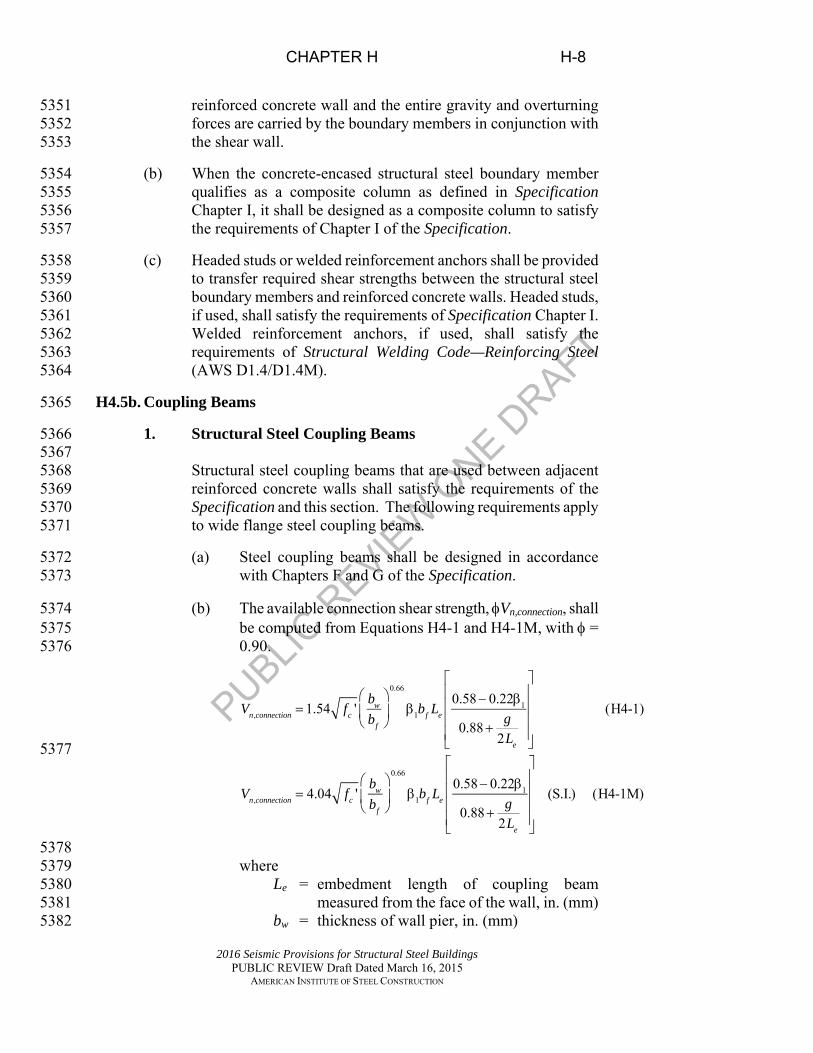
PUBLIC R
EVIEW
ONE D
RAFT
CHAPTER H H-8
2016 Seismic Provisions for Structural Steel Buildings PUBLIC REVIEW Draft Dated March 16, 2015
AMERICAN INSTITUTE OF STEEL CONSTRUCTION
reinforced concrete wall and the entire gravity and overturning 5351 forces are carried by the boundary members in conjunction with 5352 the shear wall. 5353
(b) When the concrete-encased structural steel boundary member 5354 qualifies as a composite column as defined in Specification 5355 Chapter I, it shall be designed as a composite column to satisfy 5356 the requirements of Chapter I of the Specification. 5357
(c) Headed studs or welded reinforcement anchors shall be provided 5358 to transfer required shear strengths between the structural steel 5359 boundary members and reinforced concrete walls. Headed studs, 5360 if used, shall satisfy the requirements of Specification Chapter I. 5361 Welded reinforcement anchors, if used, shall satisfy the 5362 requirements of Structural Welding Code—Reinforcing Steel 5363 (AWS D1.4/D1.4M). 5364
H4.5b. Coupling Beams 5365
1. Structural Steel Coupling Beams 5366 5367 Structural steel coupling beams that are used between adjacent 5368 reinforced concrete walls shall satisfy the requirements of the 5369 Specification and this section. The following requirements apply 5370 to wide flange steel coupling beams. 5371
(a) Steel coupling beams shall be designed in accordance 5372 with Chapters F and G of the Specification. 5373
(b) The available connection shear strength, Vn,connection, shall 5374 be computed from Equations H4-1 and H4-1M, with = 5375 0.90. 5376
Vn,connection 1.54 fc 'bw
bf
0.66
1bf Le
0.58 0.221
0.88g
2Le
(H4-1)
Vn,connection 4.04 fc 'bw
bf
0.66
1bf Le
0.58 0.221
0.88g
2Le
(S.I.) (H4-1M)
5377
5378 where 5379
Le = embedment length of coupling beam 5380 measured from the face of the wall, in. (mm) 5381
bw = thickness of wall pier, in. (mm) 5382

PUBLIC R
EVIEW
ONE D
RAFT
CHAPTER H H-9
2016 Seismic Provisions for Structural Steel Buildings PUBLIC REVIEW Draft Dated March 16, 2015
AMERICAN INSTITUTE OF STEEL CONSTRUCTION
bf = beam flange width, in. (mm) 5383 fc = concrete compressive strength, ksi (MPa) 5384 1 = factor relating depth of equivalent 5385
rectangular compressive stress block to 5386 neutral axis depth, as defined in ACI 318 5387
g = clear span of coupling beam, in. (mm) 5388
(d) Vertical wall reinforcement with nominal axial strength 5389 equal to the required shear strength, Vn, of the coupling 5390 beam shall be placed over the embedment length of the 5391 beam with two-thirds of the steel located over the first 5392 half of the embedment length. This wall reinforcement 5393 shall extend a distance of at least one tension 5394 development length above and below the flanges of the 5395 coupling beam. It is permitted to use vertical 5396 reinforcement placed for other purposes, such as for 5397 vertical boundary members, as part of the required 5398 vertical reinforcement. 5399
2. Composite Coupling Beams 5400 5401 Encased composite sections serving as coupling beams shall 5402 satisfy the following requirements: 5403
(a) Coupling beams shall have an embedment length into the 5404 reinforced concrete wall that is sufficient to develop the 5405 required shear strength, where the connection strength is 5406 calculated with Equation H4-1 or H4-1M. 5407
The available shear strength of the composite beam, 5408 Vn,comp, is computed from Equation H4-2 and H4-2M, 5409 with = 0.90. 5410
,
,
0.0632 ' (H4-2)
0.166 ' (S.I.) (H4-2M)
sr ysr cn comp p c wc c
sr ysr cn comp p c wc c
A F dV V f b d
sA F d
V V f b ds
5411
5412
5413 where 5414
Asr = area of transverse reinforcement, in.2 (mm2) 5415 Fysr = specified minimum yield stress of transverse 5416
reinforcement, ksi (MPa) 5417 Vp = 0.6FyAw, kips (N) 5418
Aw = area of steel beam web, in.2 (mm2) 5419

PUBLIC R
EVIEW
ONE D
RAFT
CHAPTER H H-10
2016 Seismic Provisions for Structural Steel Buildings PUBLIC REVIEW Draft Dated March 16, 2015
AMERICAN INSTITUTE OF STEEL CONSTRUCTION
bwc = width of concrete encasement, in. (mm) 5420 dc = effective depth of concrete encasement, in. 5421 (mm) 5422 s = spacing of transverse reinforcement, in. (mm) 5423
H4.5c. Protected Zones 5424
There are no designated protected zones. 5425
H4.6. Connections 5426
There are no additional requirements beyond Section H4.5. 5427
H4.6a. Demand Critical Welds 5428
There are no requirements for demand critical welds. 5429
H5. COMPOSITE SPECIAL SHEAR WALLS (C-SSW) 5430
H5.1. Scope 5431
Composite special shear walls (C-SSW) shall be designed in conformance 5432 with this section. This section is applicable when reinforced concrete 5433 walls are composite with structural steel elements, including structural 5434 steel or composite sections acting as boundary members for the walls and 5435 structural steel or composite coupling beams that connect two or more 5436 adjacent reinforced concrete walls. 5437
H5.2. Basis of Design 5438
C-SSW designed in accordance with these provisions are expected to 5439 provide significant inelastic deformation capacity through yielding in the 5440 reinforced concrete walls and the steel or composite elements. 5441 Reinforced concrete wall elements shall be designed to provide inelastic 5442 deformations at the design story drift consistent with ACI 318 including 5443 Chapter 18. Structural steel and composite coupling beams shall be 5444 designed to provide inelastic deformations at the design story drift 5445 through yielding in flexure or shear. Coupling beam connections and the 5446 design of the walls shall be designed to account for the expected strength 5447 including strain hardening in the coupling beams. Structural steel and 5448 composite boundary elements shall be designed to provide inelastic 5449 deformations at the design story drift through yielding due to axial force. 5450
C-SSW systems shall satisfy the requirements of Section H4 and the shear 5451 wall requirements of ACI 318 including Chapter 18, except as modified in 5452 this section. 5453
User Note: Steel coupling beams can be proportioned to be shear-critical 5454 or flexural-critical. Coupling beams with lengths g ≤1.6Mp/Vp can be 5455
PUBLIC R
EVIEW
ONE D
RAFT
CHAPTER H H-11
2016 Seismic Provisions for Structural Steel Buildings PUBLIC REVIEW Draft Dated March 16, 2015
AMERICAN INSTITUTE OF STEEL CONSTRUCTION
assumed to be shear-critical, where g, Mp, and Vp are defined in Section 5456 H4.5b(1). Coupling beams with lengths g ≥2.6Mp/Vp may be considered 5457 to be flexure-critical. Coupling beam lengths between these two values 5458 are considered to yield in flexure and shear simultaneously. 5459
H5.3. Analysis 5460
Analysis requirements of Section H4.3 shall be met with the following 5461 exceptions: 5462
(a) Cracked effective stiffness values for elastic analysis shall be 5463 assigned in accordance with ACI 318 Chapter 6 practice for wall 5464 piers and composite coupling beams. 5465
(b) Effects of shear distortion of the steel coupling beam shall be 5466 taken into account. 5467
H5.4. System Requirements 5468 5469 In addition to the system requirements of Section H4.4, the following 5470 shall be satisfied: 5471
(a) In coupled walls, coupling beams shall yield over the height of 5472 the structure followed by yielding at the base of the wall piers. 5473
(b) In coupled walls, the axial design strength of the wall at the 5474 balanced condition, Pb, shall equal or exceed the total required 5475 compressive axial strength in a wall pier, computed as the sum of 5476 the required strengths attributed to the walls from the gravity load 5477 components of the lateral load combination plus the sum of the 5478 expected beam shear strengths increased by a factor of 1.1 to 5479 reflect the effects of strain hardening of all the coupling beams 5480 framing into the walls. 5481
H5.5. Members 5482
H5.5a. Ductile Elements 5483
Welding on steel coupling beams is permitted for attachment of stiffeners, 5484 as required in Section F3.5b.4. 5485
H5.5b. Boundary Members 5486
Unencased structural steel columns shall satisfy the requirements of 5487 Section D1.1 for highly ductile members and Section H4.5a(a). 5488
In addition to the requirements of Sections H4.3(b) and H4.5a(b), the 5489 requirements in this section shall apply to walls with concrete-encased 5490 structural steel boundary members. Concrete-encased structural steel 5491

PUBLIC R
EVIEW
ONE D
RAFT
CHAPTER H H-12
2016 Seismic Provisions for Structural Steel Buildings PUBLIC REVIEW Draft Dated March 16, 2015
AMERICAN INSTITUTE OF STEEL CONSTRUCTION
boundary members that qualify as composite columns in Specification 5492 Chapter I shall meet the highly ductile member requirements of Section 5493 D1.4b(b). Otherwise, such members shall be designed as composite 5494 compression members to satisfy the requirements of ACI 318 including 5495 the special seismic requirements for boundary members in ACI 318 5496 Section 18.10.6. Transverse reinforcement for confinement of the 5497 composite boundary member shall extend a distance of 2h into the wall, 5498 where h is the overall depth of the boundary member in the plane of the 5499 wall. 5500
Headed studs or welded reinforcing anchors shall be provided as 5501 specified in Section H4.5a(c). 5502
Vertical wall reinforcement as specified in Section H4.5b.1(d) shall be 5503 confined by transverse reinforcement that meets the requirements for 5504 boundary members of ACI 318 Section 18.10.6. 5505
H5.5c. Steel Coupling Beams 5506
The design and detailing of steel coupling beams shall satisfy the 5507 following: 5508
(a) The embedment length, Le, of the coupling beam shall be 5509 computed from Equations H5-1 and H5-1M. 5510
0.66
11
0.66
11
0.58 0.221.54 ' (H5-1)
0.882
0.58 0.224.04 ' (H5-1M)
0.882
wn c f e
f
e
wn c f e
f
e
bV f b L gbL
bV f b L gbL
5511
5512
where 5513
Le = coupling beam embedment length considered to begin 5514 inside the first layer of confining reinforcement in the 5515 wall boundary member, in, (mm) 5516
g = clear span of the coupling beam plus the wall concrete 5517 cover at each end of the beam, in, (mm) 5518
Vn = expected beam shear strength computed from Equation 5519 H5-2, kips (N) 5520

PUBLIC R
EVIEW
ONE D
RAFT
CHAPTER H H-13
2016 Seismic Provisions for Structural Steel Buildings PUBLIC REVIEW Draft Dated March 16, 2015
AMERICAN INSTITUTE OF STEEL CONSTRUCTION
2 1.11.1
y py p
R MR V
g (H5-2) 5521
where 5522
Atw = area of steel beam web, in.2 (mm2). 5523
Mp = FyZ, kip-in. (N-mm) 5524
Vn = expected shear strength of a steel coupling 5525 beam, kips (N) 5526
Vp = 0.6FyAtw, kips (N) 5527 5528
(b) Structural steel coupling beams shall satisfy the requirements of 5529 Section F3.5b, except that for built-up cross sections, the flange-5530 to-web welds are permitted to be made with two-sided fillet, 5531 partial-joint-penetration, or complete-joint-penetration groove 5532 welds that develop the expected strength of the beam. When 5533 required in Section F3.5b.4, the coupling beam rotation shall be 5534 assumed as a 0.08 rad link rotation unless a smaller value is 5535 justified by rational analysis of the inelastic deformations that are 5536 expected under the design story drift. Face bearing plates shall be 5537 provided on both sides of the coupling beams at the face of the 5538 reinforced concrete wall. These stiffeners shall meet the detailing 5539 requirements of Section F3.5b.4. 5540
(c) Steel coupling beams shall comply with the requirements of 5541 Section D1.1 for highly ductile members. Flanges of coupling 5542 beams with I-shaped sections with g ≤1.6Mp/Vp are permitted to 5543 satisfy the requirements for moderately ductile members. 5544
5545 (d) Embedded steel members shall be provided with two regions of 5546
vertical transfer reinforcement attached to both the top and 5547 bottom flanges of the embedded member. The first region shall be 5548 located to coincide with the location of longitudinal wall 5549 reinforcing bars closest to the face of the wall. The second shall 5550 be placed a distance no less than d/2 from the termination of the 5551 embedment length. All transfer reinforcement bars shall be fully 5552 developed where they engage the coupling beam flanges. It is 5553 permitted to use straight, hooked or mechanical anchorage to 5554 provide development. It is permitted to use mechanical couplers 5555 welded to the flanges to attach the vertical transfer bars. The area 5556 of vertical transfer reinforcement required is computed by 5557 Equation H5-1: 5558

PUBLIC R
EVIEW
ONE D
RAFT
CHAPTER H H-14
2016 Seismic Provisions for Structural Steel Buildings PUBLIC REVIEW Draft Dated March 16, 2015
AMERICAN INSTITUTE OF STEEL CONSTRUCTION
5559 0.03 'tb c e f ysrA f L b F (H5-1) 5560
5561 where 5562 Atb = area of transfer reinforcement required in each of the first 5563
and second regions attached to each of the top and bottom 5564 flanges, in.2 (mm2) 5565
Fysr = specified minimum yield stress of transfer reinforcement, 5566 ksi (MPa) 5567
Le = embedment length, in. (mm) 5568 bf = beam flange width, in. (mm) 5569 fc = concrete compressive strength, ksi (MPa) 5570
5571 The area of vertical transfer reinforcement shall not exceed that 5572 computed by Equation H5-2: 5573
5574 0.08tb e w srA L b A (H5-2) 5575
5576 where 5577
ΣAtb = total area of transfer reinforcement provided in both the 5578 first and second regions attached to either the top or 5579 bottom flange, in.2 (mm2) 5580
Asr = area of longitudinal wall reinforcement provided over 5581 the embedment length, Le, in.2 (mm2) 5582
bw = width of wall, in. (mm) 5583
H5.5d. Composite Coupling Beams 5584
Encased composite sections serving as coupling beams shall satisfy the 5585 requirements of Section H5.5c except the requirements of Section 5586 F3.5b.4 need not be met, and Equation H5-3 shall be used instead of 5587 Equation H4-2. For all encased composite coupling beams, the limiting 5588 expected shear strength, Vcomp, is: 5589
5590
Vcomp 1.1RyVp 0.08 Rc fc ' bwcdc 1.33Ryr As Fysrdc
s(H5-3)
Vcomp 1.1RyVp 0.21 Rc fc ' bwcdc 1.33Ryr As Fysrdc
s(S.I.) (H5-3M)
5591
5592 Where 5593 5594 Fysr = yield stress of transverse reinforcement, ksi (MPa) 5595 Rc = factor to account for expected strength of concrete = 1.5 5596 Ryr = ratio of the expected yield stress of the transverse 5597

PUBLIC R
EVIEW
ONE D
RAFT
CHAPTER H H-15
2016 Seismic Provisions for Structural Steel Buildings PUBLIC REVIEW Draft Dated March 16, 2015
AMERICAN INSTITUTE OF STEEL CONSTRUCTION
reinforcement material to the specified minimum yield 5598 stress, Fysr 5599
H5.5e. Protected Zones 5600 5601
The clear span of the coupling beam between the faces of the shear walls shall be 5602 designated as a protected zone, and shall satisfy the requirements of Section 5603 D1.3. Attachment of stiffeners as required by H5.5c(b) shall be permitted. 5604
H5.6. Connections 5605
H5.6a. Demand Critical Welds 5606
The following welds are demand critical welds, and shall satisfy the 5607 requirements of Section A3.4b and I2.3: 5608
(a) Groove welds at column splices 5609
(b) Welds at the column-to-base plate connections 5610
Exception: Where it can be shown that column hinging at, or 5611 near, the base plate is precluded by conditions of restraint, and in 5612 the absence of net tension under load combinations including the 5613 overstrength seisic load, demand critical welds are not required. 5614
H5.6b. Column Splices 5615 5616 Column splices shall be designed following the requirements of Section 5617 G2.6f. 5618
H6. COMPOSITE PLATE SHEAR WALLS – CONCRETE ENCASED 5619 (C-PSW/CE) 5620
H6.1. Scope 5621
Composite plate shear walls-concrete encased (C-PSW/CE) shall be 5622 designed in conformance with this section. C-PSW/CE consist of steel 5623 plates with reinforced concrete encasement on one or both sides of the 5624 plate and structural steel or composite boundary members. 5625
H6.2. Basis of Design 5626
C-PSW/CE designed in accordance with these provisions are expected to 5627 provide significant inelastic deformation capacity through yielding in the 5628 plate webs. The horizontal boundary elements (HBEs) and vertical 5629 boundary elements (VBEs) adjacent to the composite webs shall be 5630 designed to remain essentially elastic under the maximum forces that can 5631 be generated by the fully yielded steel webs along with the reinforced 5632

PUBLIC R
EVIEW
ONE D
RAFT
CHAPTER H H-16
2016 Seismic Provisions for Structural Steel Buildings PUBLIC REVIEW Draft Dated March 16, 2015
AMERICAN INSTITUTE OF STEEL CONSTRUCTION
concrete webs after the steel web has fully yielded, except that plastic 5633 hinging at the ends of HBEs is permitted. 5634
H6.3. Analysis 5635
H6.3a. Webs 5636
The analysis shall account for openings in the web. 5637
H6.3b. Other Members and Connections 5638
Columns, beams and connections in C-PSW/CE shall be designed to 5639 resist seismic forces determined from an analysis that includes the 5640 expected strength of the steel webs in shear, 0.6RyFyAsp, where Asp is the 5641 horizontal area of the stiffened steel plate, in.2 (mm2), and any reinforced 5642 concrete portions of the wall active at the design story drift. The VBEs 5643 are permitted to yield at the base. 5644
H6.4. System Requirements 5645
H6.4a. Steel Plate Thickness 5646
Steel plates with thickness less than 3/8 in. (9.5 mm) are not permitted. 5647
H6.4b. Stiffness of Vertical Boundary Elements 5648 5649 The VBEs shall satisfy the requirements of Section F5.4a. 5650
H6.4c. HBE-to-VBE Connection Moment Ratio 5651
The beam-column moment ratio shall satisfy the requirements of Section 5652 F5.4b. 5653
H6.4d. Bracing 5654
HBE shall be braced to satisfy the requirements for moderately ductile 5655 members. 5656
H6.4e. Openings in Webs 5657
Boundary members shall be provided around openings in shear wall webs 5658 as required by analysis. 5659
H6.5. Members 5660
H6.5a. Basic Requirements 5661
Steel and composite HBE and VBE shall satisfy the requirements of 5662 Section D1.1 for highly ductile members. 5663

PUBLIC R
EVIEW
ONE D
RAFT
CHAPTER H H-17
2016 Seismic Provisions for Structural Steel Buildings PUBLIC REVIEW Draft Dated March 16, 2015
AMERICAN INSTITUTE OF STEEL CONSTRUCTION
H6.5b. Webs 5664
The design shear strength, Vn, or the allowable shear strength, Vn/, for 5665 the limit state of shear yielding with a composite plate conforming to 5666 Section H6.5c shall be taken as: 5667
Vn = 0.6AspFy (H6-1) 5668
= 0.90 (LRFD) = 1.67 (ASD) 5669
where 5670 Fy = specified minimum yield stress of the plate, ksi (MPa) 5671 Vn = nominal shear strength of the steel plate, kips (N) 5672
The available shear strength of C-PSW/CE with a plate that does not 5673 meet the stiffening requirements in Section H6.5c shall be based upon the 5674 strength of the plate as given in Section F5.5 and shall satisfy the 5675 requirements of Specification Sections G2 and G3. 5676
H6.5c. Concrete Stiffening Elements 5677
The steel plate shall be stiffened by encasement or attachment to a 5678 reinforced concrete panel. Conformance to this requirement shall be 5679 demonstrated with an elastic plate buckling analysis showing that the 5680 composite wall is able to resist a nominal shear force equal to Vn, as 5681 determined in Section H6.5b. 5682
The concrete thickness shall be a minimum of 4 in. (100 mm) on each 5683 side when concrete is provided on both sides of the steel plate and 8 in. 5684 (200 mm) when concrete is provided on one side of the steel plate. Steel 5685 headed stud anchors or other mechanical connectors shall be provided to 5686 prevent local buckling and separation of the plate and reinforced 5687 concrete. Horizontal and vertical reinforcement shall be provided in the 5688 concrete encasement to meet or exceed the requirements in ACI 318 5689 Section 11.6 and 11.7. The reinforcement ratio in both directions shall not 5690 be less than 0.0025. The maximum spacing between bars shall not exceed 5691 18 in. (450 mm). 5692
H6.5d. Boundary Members 5693
Structural steel and composite boundary members shall be designed to 5694 resist the expected shear strength of steel plate and any reinforced 5695 concrete portions of the wall active at the design story drift. Composite 5696 and reinforced concrete boundary members shall also satisfy the 5697 requirements of Section H5.5b. Steel boundary members shall also 5698 satisfy the requirements of Section F5. 5699
H6.5e. Protected Zones 5700

PUBLIC R
EVIEW
ONE D
RAFT
CHAPTER H H-18
2016 Seismic Provisions for Structural Steel Buildings PUBLIC REVIEW Draft Dated March 16, 2015
AMERICAN INSTITUTE OF STEEL CONSTRUCTION
There are no designated protected zones. 5701
H6.6. Connections 5702
H6.6a. Demand Critical Welds 5703
The following welds are demand critical welds, and shall satisfy the 5704 requirements of Section A3.4b and I2.3: 5705
(a) Groove welds at column splices 5706
(b) Welds at the column-to-base plate connections 5707
Exception: Where it can be shown that column hinging at, or 5708 near, the base plate is precluded by conditions of restraint, and in 5709 the absence of net tension under load combinations including the 5710 overstrength seismic load, demand critical welds are not required. 5711
(c) Welds at HBE-to-VBE connections 5712
H6.6b. HBE-to-VBE Connections 5713
HBE-to-VBE connections shall satisfy the requirements of Section F5.6b. 5714
H6.6c. Connections of Steel Plate to Boundary Elements 5715
The steel plate shall be continuously welded or bolted on all edges to the 5716 structural steel framing and/or steel boundary members, or the steel 5717 component of the composite boundary members. Welds and/or slip-5718 critical high-strength bolts required to develop the nominal shear strength 5719 of the plate shall be provided. 5720
H6.6d. Connections of Steel Plate to Reinforced Concrete Panel 5721
The steel anchors between the steel plate and the reinforced concrete 5722 panel shall be designed to prevent its overall buckling. Steel anchors shall 5723 be designed to satisfy the following conditions: 5724
(a) Tension in the Connector 5725
The steel anchor shall be designed to resist the tension force 5726 resulting from inelastic local buckling of the steel plate. 5727
(b) Shear in the Connector 5728
The steel anchors collectively shall be designed to transfer the 5729 expected strength in shear of the steel plate or reinforced concrete 5730 panel, whichever is smaller. 5731
H6.6e. Column Splices 5732

PUBLIC R
EVIEW
ONE D
RAFT
CHAPTER H H-19
2016 Seismic Provisions for Structural Steel Buildings PUBLIC REVIEW Draft Dated March 16, 2015
AMERICAN INSTITUTE OF STEEL CONSTRUCTION
In addition to the requirements of Section D2.5, column splices shall 5733 comply with the requirements of this section. Where welds are used to 5734 make the splice, they shall be complete-joint-penetration groove welds. 5735 When column splices are not made with groove welds, they shall have a 5736 required flexural strength that is at least equal to the nominal flexural 5737 strength, Mpcc, of the smaller composite column. The required shear 5738 strength of column web splices shall be at least equal to Mpcc/H, where 5739 Mpcc is the sum of the nominal flexural strengths at the top and bottom 5740 ends of the composite column. For composite columns, the nominal 5741 flexural strength shall satisfy the requirements of Specification Chapter I 5742 with consideration of the required axial strength, Prc. 5743 5744
H7. COMPOSITE PLATE SHEAR WALLS—CONCRETE FILLED 5745 (C-PSW/CF) 5746
H7.1. Scope 5747
Composite plate shear walls-concrete filled (C-PSW/CF) shall be 5748 designed in conformance with this section. This section is applicable to 5749 composite plate shear walls that consist of two planar steel web plates 5750 with concrete fill between the plates, with or without boundary elements. 5751 Composite action between the plates and concrete fill shall be achieved 5752 using either tie bars or a combination of tie bars and shear studs. The two 5753 steel web plates shall be of equal thickness and shall be placed at a 5754 constant distance from each other and connected using tie bars. When 5755 boundary are included, they shall be either half circular steel section of 5756 diameter equal to the distance between the two web plates or a circular 5757 concrete-filled steel tube. 5758 5759 5760
H7.2. Basis of Design 5761 5762
C-PSW/CF with boundary elements, designed in accordance with these 5763 provisions, are expected to provide significant inelastic deformation 5764 capacity through developing plastic moment strength of the composite 5765 C-PSW/CF cross section, by yielding of the entire skin plate and the 5766 concrete attaining its compressive strength. The cross section shall be 5767 detailed such that it is able to attain its plastic moment strength. Shear 5768 yielding of the steel web skin plates shall not be the governing 5769 mechanism. 5770 5771 C-PSW/CF without boundary elements designed in accordance to these 5772 provisions are expected to provide inelastic deformation capacity by 5773 developing yield moment strength of the composite C-PSW/CF cross 5774 section, by flexural tension yielding of the steel plates. The walls shall be 5775

PUBLIC R
EVIEW
ONE D
RAFT
CHAPTER H H-20
2016 Seismic Provisions for Structural Steel Buildings PUBLIC REVIEW Draft Dated March 16, 2015
AMERICAN INSTITUTE OF STEEL CONSTRUCTION
detailed such that flexural compression yielding occurs before local 5776 buckling of the steel plates. 5777 5778
H7.3. Analysis 5779
Analysis shall satisfy the following: 5780 5781 (a) Effective flexural stiffness of the wall shall be calculated per 5782
Specification Equation I2-12, with 3C taken equal to 0.40. 5783
5784 (b) The shear stiffness of the wall shall be calculated using the shear 5785
stiffness of the composite cross section. 5786 5787
H7.4. System Requirements 5788 5789
H7.4a. Steel Web Plate of C-PSW/CF with Boundary Elements 5790 5791
The minimum thickness of the steel web plate shall be: 5792
10.55 ymin
Ft w
E (H7-1) 5793
where 5794 w1 = maximum spacing of tie bars in vertical and horizontal 5795
directions, in. (mm) 5796 5797 When tie bars are welded with the web plate, the thickness of the plate 5798 shall develop the tension strength of the tie bars. 5799 5800
H7.4b. Steel Plate of C-PSW/CF without Boundary Elements 5801 5802
The minimum thickness of the steel plates shall be: 5803
11.0 ymin
Ft w
E (H7-2) 5804
where 5805 w1 = maximum spacing of tie bars or shear studs in the vertical and 5806
horizontal directions, in. (mm) 5807
H7.4c. Half Circular or Full Circular End of C-PSW/CF with Boundary 5808 Elements 5809
5810 The D/tHSS ratio for the circular part of the C-PSW/CF cross section shall 5811 conform to: 5812

PUBLIC R
EVIEW
ONE D
RAFT
CHAPTER H H-21
2016 Seismic Provisions for Structural Steel Buildings PUBLIC REVIEW Draft Dated March 16, 2015
AMERICAN INSTITUTE OF STEEL CONSTRUCTION
0.044HSS y
D Et F
(H7-3) 5813
where 5814 D = outside diameter of round HSS, in. (mm) 5815 tHSS = thickness of HSS, in. (mm) 5816
5817 H7.4d. Spacing of Tie Bars in C-PSW/CF with or without Boundary 5818
Elements 5819 5820
Tie bars shall be distributed in both vertical and horizontal directions. 5821 5822
H7.4e. Tie Bar Diameter in C-PSW/CF with or without Boundary Elements 5823 5824
Tie bars shall be designed to elastically resist the tension force, Treq,, equal 5825 to: 5826 1 2reqT T T (H7-4) 5827
T1 is the tension force resulting from the locally buckled web plates 5828 developing plastic hinges on horizontal yield lines along the tie bars and at 5829 mid-vertical distance between tie-bars, and is determined as follows: 5830
221 ,
1
2 s y platewT t Fw
(H7-5) 5831
where 5832 ts = the thickness of steel web plate provided, in. (mm) 5833 1 2,w w = vertical and horizontal spacing of tie bars, in. (mm), 5834
respectively 5835 5836 T2 is the tension force that develops to prevent splitting of the concrete 5837 element on a plane parallel to the steel plate. 5838
, 22 2
1
6
418 1
s y plate w
w
min
t F t wTw t
w
(H7-6) 5839
5840 where 5841 tw = total thickness of wall, in. (mm) 5842 wmin = minimum of w1 and w2, in. (mm) 5843
H7.4f. Connection between Tie Bars and Steel Plates 5844
Connection of the tie bars to the steel plate shall be able to develop the full 5845 tension strength of the tie bar. 5846 5847

PUBLIC R
EVIEW
ONE D
RAFT
CHAPTER H H-22
2016 Seismic Provisions for Structural Steel Buildings PUBLIC REVIEW Draft Dated March 16, 2015
AMERICAN INSTITUTE OF STEEL CONSTRUCTION
H7.4g. Connection between C-PSW/CF Steel Components 5848 5849 Welds between the steel web plate and the half-circular or full-circular 5850 ends of the cross section shall be complete-joint-penetration groove welds. 5851 5852
H7.4h. C-PSW/CF and Foundation Connection 5853 5854
The connection between C-PSW/CF and the foundation shall be detailed 5855 such that the connection is able to transfer the base shear force and the 5856 axial force acting together with the overturning moment, corresponding to 5857 1.1 times the plastic composite flexural strength of the wall, where the 5858 plastic flexural composite strength is obtained by the plastic stress 5859 distribution method described in Specification Section I1.2a assuming that 5860 the steel components have reached a stress equal to the expected yield 5861 strength, RyFy, in either tension or compression and that concrete 5862 components in compression due to axial force and flexure have reached a 5863 stress of cf . 5864
5865 H7.5. System Requirements 5866
H7.5a Flexural Strength 5867
The nominal plastic moment strength of the C-PSW/CF with boundary 5868 elements shall be calculated considering that all the concrete in 5869 compression has reached its specified compressive strength, fc, and that 5870 the steel in tension and compression has reached its specified minimum 5871 yield strength, Fy, as determined based on the location of the plastic 5872 neutral axis. 5873
The nominal moment strength of the C-PSW/CF without boundary 5874 elements shall be calculated as the yield moment, My, corresponding to 5875 yielding of the steel plate in flexural tension and first yield in flexural 5876 compression. The strength at first yield shall be calculated assuming a 5877 linear elastic stress distribution with maximum concrete compressive 5878 stress limited to 0.7 fc and maximum steel stress limited to Fy. 5879
User Note: The definition and calculation of the yield moment, My, for 5880 C-PSW/CF without boundary elements is very similar to the definition 5881 and calculation of yield moment, My, for noncompact filled composite 5882 members in Specification Section I3.4b(b). 5883
H7.5b Shear Strength 5884
The available shear strength of C-PSW/CF shall be determined as 5885 follows: 5886

PUBLIC R
EVIEW
ONE D
RAFT
CHAPTER H H-23
2016 Seismic Provisions for Structural Steel Buildings PUBLIC REVIEW Draft Dated March 16, 2015
AMERICAN INSTITUTE OF STEEL CONSTRUCTION
(a) The design shear strength, Vni, or the allowable shear strength, 5887 Vni/, of the C-PSW/CF with boundary elements shall be 5888 determined as follows: 5889
5890 ni y swV F A (H7-7) 5891
v = 0.90 (LRFD) Ωv = 1.67 (ASD) 5892 5893 where 5894
1.11 5.16 1.0 (H7-8) 5895
strength adjusted reinforcement ratio
1,000sw yw
cw c
A FA f
(H7-9)
5896
1
12sw yw
cw c
A FA f
(H7-9M) 5897
Fyw= specified minimum yield stress of web skin plates, 5898 ksi (MPa) 5899
fc = specified compressive strength of concrete, ksi 5900 (MPa) 5901
Asw =area of steel web plates, in.2 (mm2) 5902 Acw = area of concrete between web plates, in.2 (mm2) 5903
5904
User Note: For most cases, 0.9 ≤ κ ≤ 1.0. 5905
(b) The nominal shear strength of the C-PSW/CF without boundary 5906 elements shall be calculated for the steel plates alone, in 5907 accordance with Section D1.4c. 5908
5909

PUBLIC R
EVIEW
ONE D
RAFT
CHAPTER I I-1
2016 Seismic Provisions for Structural Steel Buildings PUBLIC REVIEW Draft Dated March 16, 2015
AMERICAN INSTITUTE OF STEEL CONSTRUCTION
6000 CHAPTER I 6001
6002 FABRICATION AND ERECTION 6003
6004 This chapter addresses requirements for fabrication and erection. 6005 6006 User Note: All requirements of Specification Chapter M also apply, unless 6007 specifically modified by these Provisions. 6008 6009 The chapter is organized as follows: 6010 6011 I1. Shop and Erection Drawings 6012 I2. Fabrication and Erection 6013 6014 I1. SHOP AND ERECTION DRAWINGS 6015 6016 I1.1. Shop Drawings for Steel Construction 6017
6018 Shop drawings shall indicate the work to be performed, and include items 6019 required by the Specification, the AISC Code of Standard Practice for 6020 Steel Buildings and Bridges, the applicable building code, the 6021 requirements of Sections A4.1 and A4.2, and the following, as applicable: 6022 6023 (a) Locations of pretensioned bolts 6024 (b) Locations of Class A, or higher, faying surfaces 6025 (c) Gusset plates drawn to scale when they are designed to 6026
accommodate inelastic rotation 6027 (d) Weld access hole dimensions, surface profile and finish 6028
requirements 6029 (e) Nondestructive testing (NDT) where performed by the 6030
fabricator 6031 6032 I1.2. Erection Drawings for Steel Construction 6033
6034 Erection drawings shall indicate the work to be performed, and include 6035 items required by the Specification, the AISC Code of Standard Practice 6036 for Steel Buildings and Bridges, the applicable building code, the 6037 requirements of Sections A4.1 and A4.2, and the following, as applicable: 6038
6039 (a) Locations of pretensioned bolts 6040 (b) Those joints or groups of joints in which a specific assembly 6041
order, welding sequence, welding technique or other special 6042 precautions are required 6043
6044 I1.3. Shop and Erection Drawings for Composite Construction 6045

PUBLIC R
EVIEW
ONE D
RAFT
CHAPTER I I-2
2016 Seismic Provisions for Structural Steel Buildings PUBLIC REVIEW Draft Dated March 16, 2015
AMERICAN INSTITUTE OF STEEL CONSTRUCTION
6046 Shop drawings and erection drawings for the steel components of 6047 composite steel-concrete construction shall satisfy the requirements of 6048 Sections I1.1 and I1.2. The shop drawings and erection drawings shall 6049 also satisfy the requirements of Section A4.3. 6050 6051 User Note: For reinforced concrete and composite steel-concrete 6052 construction, the provisions of ACI 315 Details and Detailing of 6053 Concrete Reinforcement and ACI 315-R Manual of Engineering and 6054 Placing Drawings for Reinforced Concrete Structures apply. 6055
6056 I2. FABRICATION AND ERECTION 6057 6058 I2.1. Protected Zone 6059 6060
A protected zone designated by these Provisions or ANSI/AISC 358 shall 6061 comply with the following requirements: 6062 6063 (a) Within the protected zone, holes, tack welds, erection aids, air-arc 6064
gouging, and unspecified thermal cutting from fabrication or 6065 erection operations shall be repaired as required by the engineer 6066 of record. 6067
6068 (b) Steel headed stud anchors shall not be placed on beam flanges 6069
within the protected zone. 6070 6071 (c) Arc spot welds as required to attach decking are permitted. 6072 6073 (d) Decking attachments that penetrate the beam flange shall not be 6074
placed on beam flanges within the protected zone, except powder 6075 actuated fasteners up to 0.18 in. diameter are permitted. 6076
6077 (e) Welded, bolted, screwed or shot-in attachments for perimeter 6078
edge angles, exterior facades, partitions, duct work, piping or 6079 other construction shall not be placed within the protected zone. 6080
6081 Exception: Other attachments are permitted where designated or 6082 approved by the engineer of record. See Section D1.3. 6083 6084 User Note: AWS D1.8/D1.8M clause 6.15 contains requirements for 6085 weld removal and the repair of gouges and notches in the protected zone. 6086
6087 I2.2. Bolted Joints 6088 6089
Bolted joints shall satisfy the requirements of Section D2.2. 6090 6091

PUBLIC R
EVIEW
ONE D
RAFT
CHAPTER I I-3
2016 Seismic Provisions for Structural Steel Buildings PUBLIC REVIEW Draft Dated March 16, 2015
AMERICAN INSTITUTE OF STEEL CONSTRUCTION
I2.3. Welded Joints 6092 6093
Welding and welded connections shall be in accordance with Structural 6094 Welding Code—Steel (AWS D1.1/D1.1M), hereafter referred to as AWS 6095 D1.1/D1.1M, and AWS D1.8/D1.8M. 6096 6097 Welding procedure specifications (WPSs) shall be approved by the 6098 engineer of record. 6099 6100 Weld tabs shall be in accordance with AWS D1.8/D1.8M clause 6.10, 6101 except at the outboard ends of continuity-plate-to-column welds, weld 6102 tabs and weld metal need not be removed closer than ¼ in. (6 mm) from 6103 the continuity plate edge. 6104 6105 AWS D1.8/D1.8M clauses relating to fabrication shall apply equally to 6106 shop fabrication welding and to field erection welding. 6107 6108 User Note: AWS D1.8/D1.8M was specifically written to provide 6109 additional requirements for the welding of seismic force resisting 6110 systems, and has been coordinated wherever possible with these 6111 Provisions. AWS D1.8/D1.8M requirements related to fabrication and 6112 erection are organized as follows, including normative (mandatory) 6113 annexes: 6114 6115 (a) General Requirements 6116 (b) Reference Documents 6117 (c) Definitions 6118 (d) Welded Connection Details 6119 (e) Welder Qualification 6120 (f) Fabrication 6121 Annex A. WPS Heat Input Envelope Testing of Filler Metals for 6122
Demand Critical Welds 6123 Annex B. Intermix CVN Testing of Filler Metal Combinations (where 6124
one of the filler metals is FCAW-S) 6125 Annex C. Supplemental Welder Qualification for Restricted Access 6126
Welding 6127 Annex D. Supplemental Testing for Extended Exposure Limits for 6128
FCAW Filler Metals 6129 6130 AWS D1.8/D1.8M requires the complete removal of all weld tab 6131 material, leaving only base metal and weld metal at the edge of the joint. 6132 This is to remove any weld discontinuities at the weld ends, as well as 6133 facilitate magnetic particle testing (MT) of this area. At continuity plates, 6134 these Provisions permit a limited amount of weld tab material to remain 6135 because of the reduced strains at continuity plates, and any remaining 6136 weld discontinuities in this weld end region would likely be of little 6137

PUBLIC R
EVIEW
ONE D
RAFT
CHAPTER I I-4
2016 Seismic Provisions for Structural Steel Buildings PUBLIC REVIEW Draft Dated March 16, 2015
AMERICAN INSTITUTE OF STEEL CONSTRUCTION
significance. Also, weld tab removal sites at continuity plates are not 6138 subjected to MT. 6139 6140 AWS D1.8/D1.8M clause 6 is entitled “Fabrication,” but the intent of 6141 AWS is that all provisions of AWS D1.8/D1.8M apply equally to 6142 fabrication and erection activities as described in the Specification and in 6143 these Provisions. 6144
6145 I2.4. Continuity Plates and Stiffeners 6146
6147 Corners of continuity plates and stiffeners placed in the webs of rolled 6148 shapes shall be detailed in accordance with AWS D1.8 clause 4.1. 6149
PUBLIC R
EVIEW
ONE D
RAFT
CHAPTER J J-1
2016 Seismic Provisions for Structural Steel Buildings PUBLIC REVIEW Draft Dated March 16, 2015
AMERICAN INSTITUTE OF STEEL CONSTRUCTION
CHAPTER J 6200 6201
QUALITY CONTROL AND QUALITY ASSURANCE 6202 6203
This chapter addresses requirements for quality control and quality assurance. 6204 6205 User Note: All requirements of Specification Chapter N also apply, unless 6206 specifically modified by these Provisions. 6207 6208 The chapter is organized as follows: 6209 6210
J1. Scope 6211 J2. Fabricator and Erector Documents 6212 J3. Quality Assurance Agency Documents 6213 J4. Inspection and Nondestructive Testing Personnel 6214 J5. Inspection Tasks 6215 J6. Welding Inspection and Nondestructive Testing 6216 J7. Inspection of High-Strength Bolting 6217 J8. Other Steel Structure Inspections 6218 J9. Inspection of Composite Structures 6219 J10. Inspection of Piling 6220 6221
J1. SCOPE 6222 6223
Quality Control (QC) as specified in this chapter shall be provided by the 6224 fabricator, erector or other responsible contractor as applicable. Quality 6225 Assurance (QA) as specified in this chapter shall be provided by others 6226 when required by the authority having jurisdiction (AHJ), applicable 6227 building code (ABC), purchaser, owner or engineer of record (EOR). 6228 Nondestructive testing (NDT) shall be performed by the agency or firm 6229 responsible for Quality Assurance, except as permitted in accordance 6230 with Specification Section N7. 6231 6232 User Note: The quality assurance plan of this section is considered 6233 adequate and effective for most seismic force resisting systems and 6234 should be used without modification. The quality assurance plan is 6235 intended to ensure that the seismic force resisting system is significantly 6236 free of defects that would greatly reduce the ductility of the system. 6237 There may be cases (for example, nonredundant major transfer members, 6238 or where work is performed in a location that is difficult to access) where 6239 supplemental testing might be advisable. Additionally, where the 6240 fabricator's or erector’s quality control program has demonstrated the 6241 capability to perform some tasks this plan has assigned to quality 6242 assurance, modification of the plan could be considered. 6243
6244

PUBLIC R
EVIEW
ONE D
RAFT
CHAPTER J J-2
2016 Seismic Provisions for Structural Steel Buildings PUBLIC REVIEW Draft Dated March 16, 2015
AMERICAN INSTITUTE OF STEEL CONSTRUCTION
J2. FABRICATOR AND ERECTOR DOCUMENTS 6245 6246 J2.1. Documents to be Submitted for Steel Construction 6247 6248
In addition to the requirements of Specification Section N3.1, the 6249 following documents shall be submitted for review by the EOR or the 6250 EOR’s designee, prior to fabrication or erection of the affected work, as 6251 applicable: 6252
6253 (a) Welding procedure specifications (WPS) 6254 6255 (b) Copies of the manufacturer’s typical certificate of conformance 6256
for all electrodes, fluxes and shielding gasses to be used 6257 6258 (c) For demand critical welds, applicable manufacturer’s 6259
certifications that the filler metal meets the supplemental notch 6260 toughness requirements, as applicable. When the filler metal 6261 manufacturer does not supply such supplemental certifications, 6262 the fabricator or erector, as applicable, shall have the necessary 6263 testing performed and provide the applicable test reports 6264
6265 (d) Manufacturer’s product data sheets or catalog data for SMAW, 6266
FCAW and GMAW composite (cored) filler metals to be used 6267 6268 (e) Bolt installation procedures 6269 6270 (d) Specific assembly order, welding sequence, welding technique, or 6271
other special precautions for joints or groups of joints where such 6272 items are designated to be submitted to the engineer of record 6273
6274 J2.2. Documents to be Available for Review for Steel Construction 6275 6276
Additional documents as required by the EOR in the contract documents 6277 shall be available by the fabricator and erector for review by the EOR or 6278 the EOR’s designee prior to fabrication or erection, as applicable. 6279 6280 The fabricator and erector shall retain their document(s) for at least one 6281 year after substantial completion of construction. 6282 6283
J2.3. Documents to be Submitted for Composite Construction 6284 6285
The following documents shall be submitted by the responsible 6286 contractor for review by the EOR or the EOR’s designee, prior to 6287 concrete production or placement, as applicable: 6288
6289 (a) Concrete mix design and test reports for the mix design 6290

PUBLIC R
EVIEW
ONE D
RAFT
CHAPTER J J-3
2016 Seismic Provisions for Structural Steel Buildings PUBLIC REVIEW Draft Dated March 16, 2015
AMERICAN INSTITUTE OF STEEL CONSTRUCTION
6291 (b) Reinforcing steel shop drawings 6292 6293 (c) Concrete placement sequences, techniques and restriction 6294
6295 J2.4. Documents to be Available for Review for Composite Construction 6296 6297
The following documents shall be available from the responsible 6298 contractor for review by the EOR or the EOR’s designee prior to 6299 fabrication or erection, as applicable, unless specified to be submitted: 6300 6301 (a) Material test reports for reinforcing steel 6302 6303 (b) Inspection procedures 6304 6305 (c) Nonconformance procedure 6306 6307 (d) Material control procedure 6308 6309 (e) Welder performance qualification records (WPQR) as required 6310
by AWS D1.4/D1.4M 6311 6312 (f) QC Inspector qualifications 6313 6314 The responsible contractor shall retain their document(s) for at least one 6315 year after substantial completion of construction. 6316
6317 J3. QUALITY ASSURANCE AGENCY DOCUMENTS 6318 6319
The agency responsible for quality assurance shall submit the following 6320 documents to the authority having jurisdiction, the EOR, and the owner 6321 or owner’s designee: 6322 6323 (a) QA agency’s written practices for the monitoring and control of 6324
the agency’s operations. The written practice shall include: 6325 6326 (1) The agency's procedures for the selection and 6327
administration of inspection personnel, describing the 6328 training, experience and examination requirements for 6329 qualification and certification of inspection personnel, and 6330
6331 (2) The agency’s inspection procedures, including general 6332
inspection, material controls, and visual welding 6333 inspection 6334
6335 (b) Qualifications of management and QA personnel designated for 6336

PUBLIC R
EVIEW
ONE D
RAFT
CHAPTER J J-4
2016 Seismic Provisions for Structural Steel Buildings PUBLIC REVIEW Draft Dated March 16, 2015
AMERICAN INSTITUTE OF STEEL CONSTRUCTION
the project 6337 6338 (c) Qualification records for inspectors and NDT technicians 6339
designated for the project 6340 6341 (d) NDT procedures and equipment calibration records for NDT to 6342
be performed and equipment to be used for the project 6343 6344 (e) For composite construction, concrete testing procedures and 6345
equipment 6346 6347
J4. INSPECTION AND NONDESTRUCTIVE TESTING 6348 PERSONNEL 6349
6350 In addition to the requirements of Specification Sections N4.1 and N4.2, 6351 visual welding inspection and NDT shall be conducted by personnel 6352 qualified in accordance with AWS D1.8/D1.8M clause 7.2. In addition to 6353 the requirements of Specification Section N4.3, ultrasonic testing 6354 technicians shall be qualified in accordance with AWS D1.8/D1.8M 6355 clause 7.2.4. 6356 6357 User Note: The recommendations of the International Code Council 6358 Model Program for Special Inspection should be considered a minimum 6359 requirement to establish the qualifications of a bolting inspector. 6360
6361 J5. INSPECTION TASKS 6362 6363
Inspection tasks and documentation for QC and QA for the seismic force 6364 resisting system (SFRS) shall be as provided in the tables in Sections J6, 6365 J7, J8, J9 and J10. The following entries are used in the tables: 6366 6367
J5.1. Observe (O) 6368 6369 The inspector shall observe these functions on a random, daily basis. 6370 Operations need not be delayed pending observations. 6371 6372
J5.2. Perform (P) 6373 6374 These inspections shall be performed prior to the final acceptance of 6375 the item. 6376 6377
J5.3. Document (D) 6378 6379 The inspector shall prepare reports indicating that the work has been 6380 performed in accordance with the contract documents. The report need 6381 not provide detailed measurements for joint fit-up, WPS settings, 6382

PUBLIC R
EVIEW
ONE D
RAFT
CHAPTER J J-5
2016 Seismic Provisions for Structural Steel Buildings PUBLIC REVIEW Draft Dated March 16, 2015
AMERICAN INSTITUTE OF STEEL CONSTRUCTION
completed welds, or other individual items listed in the tables. For shop 6383 fabrication, the report shall indicate the piece mark of the piece inspected. 6384 For field work, the report shall indicate the reference grid lines and floor 6385 or elevation inspected. Work not in compliance with the contract 6386 documents and whether the noncompliance has been satisfactorily 6387 repaired shall be noted in the inspection report. 6388 6389
J5.4. Coordinated Inspection 6390 6391 Where a task is stipulated to be performed by both QC and QA, 6392 coordination of the inspection function between QC and QA is permitted 6393 in accordance with Specification Section N5.3. 6394 6395
J6. WELDING INSPECTION AND NONDESTRUCTIVE TESTING 6396 6397
Welding inspection and nondestructive testing shall satisfy the 6398 requirements of the Specification, this section and AWS D1.8/D1.8M. 6399 6400 User Note: AWS D1.8/D1.8M was specifically written to provide 6401 additional requirements for the welding of seismic force resisting 6402 systems, and has been coordinated when possible with these Provisions. 6403 AWS D1.8/D1.8M requirements related to inspection and nondestructive 6404 testing are organized as follows, including normative (mandatory) 6405 annexes: 6406 6407 1. General Requirements 6408 7. Inspection 6409 Annex F. Supplemental Ultrasonic Technician Testing 6410 Annex G. Supplemental Magnetic Particle Testing Procedures 6411 Annex H. Flaw Sizing by Ultrasonic Testing 6412
6413 J6.1. Visual Welding Inspection 6414 6415
All requirements of the Specification shall apply, except as specifically 6416 modified by AWS D1.8/D1.8M. 6417 6418 Visual welding inspection shall be performed by both quality control and 6419 quality assurance personnel. As a minimum, tasks shall be as listed in 6420 Tables J6-1, J6-2 and J6-3. 6421
6422 6423

PUBLIC R
EVIEW
ONE D
RAFT
CHAPTER J J-6
2016 Seismic Provisions for Structural Steel Buildings PUBLIC REVIEW Draft Dated March 16, 2015
AMERICAN INSTITUTE OF STEEL CONSTRUCTION
6424
TABLE J6-1 Visual Inspection Tasks Prior to Welding
Visual Inspection Tasks Prior to Welding QC QA
Task Doc. Task Doc.Material identification (Type/Grade) O - O - Welder identification system O - O - Fit-up of Groove Welds (including joint geometry)
P/O**
-
O
-
- Joint preparation - Dimensions (alignment, root opening, root face, bevel) - Cleanliness (condition of steel surfaces) - Tacking (tack weld quality and location) - Backing type and fit (if applicable) Configuration and finish of access holes O - O - Fit-up of Fillet Welds - Dimensions (alignment, gaps at root) - Cleanliness (condition of steel surfaces) - Tacking (tack weld quality and location)
P/O** - O -
** Following performance of this inspection task for ten welds to be made by a given welder, with the welder demonstrating understanding of requirements and possession of skills and tools to verify these items, the Perform designation of this task shall be reduced to Observe, and the welder shall perform this task. In the instance that the inspector determines that the welder has discontinued performance of this task, the task shall be returned to Perform until such time as the Inspector has re-established adequate assurance that the welder will perform the inspection tasks listed.
6425 6426

PUBLIC R
EVIEW
ONE D
RAFT
CHAPTER J J-7
2016 Seismic Provisions for Structural Steel Buildings PUBLIC REVIEW Draft Dated March 16, 2015
AMERICAN INSTITUTE OF STEEL CONSTRUCTION
6427
TABLE J6-2 Visual Inspection Tasks During Welding
Visual Inspection Tasks During Welding QC QA
Task Doc. Task Doc.WPS followed
- Settings on welding equipment - Travel speed - Selected welding materials - Shielding gas type/flow rate - Preheat applied - Interpass temperature maintained (min/max.) - Proper position (F, V, H, OH) - Intermix of filler metals avoided unless approved
O - O -
Use of qualified welders O - O - Control and handling of welding consumables
O - O - - Packaging - Exposure control Environmental conditions
O - O - - Wind speed within limits - Precipitation and temperature Welding techniques
O - O - - Interpass and final cleaning - Each pass within profile limitations - Each pass meets quality requirements No welding over cracked tacks O - O -
6428 6429

PUBLIC R
EVIEW
ONE D
RAFT
CHAPTER J J-8
2016 Seismic Provisions for Structural Steel Buildings PUBLIC REVIEW Draft Dated March 16, 2015
AMERICAN INSTITUTE OF STEEL CONSTRUCTION
6430
TABLE J6-3 Visual Inspection Tasks After Welding
Visual Inspection Tasks After Welding QC QA
Task Doc. Task Doc.Welds cleaned O - O - Size, length, and location of welds P - P - Welds meet visual acceptance criteria
P D P D
- Crack prohibition - Weld/base-metal fusion - Crater cross section - Weld profiles and size - Undercut - Porosity k-area1 P D P D Placement of reinforcing or contouring fillet welds (if required) P D P D Backing removed, weld tabs removed and finished, and fillet welds added (if required) P D P D
Repair activities P - P D 1 When welding of doubler plates, continuity plates or stiffeners has been performed in the k-area, visually inspect the web k-area for cracks within 3 in. (75 mm) of the weld. The visual inspection shall be performed no sooner than 48 hours following completion of the welding.
6431 6432
J6.2. NDT of Welded Joints 6433 6434
In addition to the requirements of Specification Section N5.5, 6435 nondestructive testing of welded joints shall be as required in this section: 6436
6437 6438 J6.2a. CJP Groove Weld NDT 6439
6440 Ultrasonic testing (UT) shall be performed on 100% of CJP groove welds 6441 in materials 5/16 in. (8 mm) thick or greater. Ultrasonic testing in 6442 materials less than 5/16 in. (8 mm) thick is not required. Weld 6443 discontinuities shall be accepted or rejected on the basis of criteria of 6444 AWS D1.1/D1.1M Table 6.2. Magnetic particle testing shall be 6445 performed on 25% of all beam-to-column CJP groove welds. The rate of 6446 UT and MT is permitted to be reduced in accordance with Sections J6.2h 6447 and J6.2i, respectively. 6448 6449 Exception: For ordinary moment frames in structures in risk categories I 6450 or II, UT and MT of CJP groove welds are required only for demand 6451 critical welds. 6452 6453

PUBLIC R
EVIEW
ONE D
RAFT
CHAPTER J J-9
2016 Seismic Provisions for Structural Steel Buildings PUBLIC REVIEW Draft Dated March 16, 2015
AMERICAN INSTITUTE OF STEEL CONSTRUCTION
User Note: For structures in Risk Category III or IV, AISC 360 section 6454 N5.5b requires that the UT be performed by QA on all CJP groove welds 6455 subject to transversely applied tension loading in butt, T- and corner 6456 joints, in material 5/16 in. (8 mm) thick or greater. 6457
6458 J6.2b. Column Splice and Column to Base Plate PJP Groove Weld NDT 6459
UT shall be performed by QA on 100% of PJP groove welds in column 6460 splices and column to base plate welds. 6461 6462 Weld discontinuities shall be accepted or rejected on the basis of criteria 6463 of AWS D1.1/D1.1M Table 6.2. The rate of UT is permitted to be 6464 reduced in accordance with Section J6.2h. 6465 6466 User Note: In accordance with AWS D1.8 clause 7.10.5, when UT of 6467 PJP groove welded joints is required, rejection shall not be on the basis of 6468 the indication rating from the root area of the weld. 6469 6470
6471 J6.2c.Base Metal NDT for Lamellar Tearing and Laminations 6472 6473
After joint completion, base metal thicker than 1½ in. (38 mm) loaded in 6474 tension in the through-thickness direction in tee and corner joints, where 6475 the connected material is greater than ¾ in. (19 mm) and contains CJP 6476 groove welds, shall be ultrasonically tested for discontinuities behind and 6477 adjacent to the fusion line of such welds. Any base metal discontinuities 6478 found within t/4 of the steel surface shall be accepted or rejected on the 6479 basis of criteria of AWS D1.1/D1.1M Table 6.2, where t is the thickness 6480 of the part subjected to the through-thickness strain. 6481
6482 J6.2d.Beam Cope and Access Hole NDT 6483 6484
At welded splices and connections, thermally cut surfaces of beam copes 6485 and access holes shall be tested using magnetic particle testing or 6486 penetrant testing, when the flange thickness exceeds 1½ in. (38 mm) for 6487 rolled shapes, or when the web thickness exceeds 1½ in. (38 mm) for 6488 built-up shapes. 6489
6490 J6.2e. Reduced Beam Section Repair NDT 6491 6492
Magnetic particle testing shall be performed on any weld and adjacent 6493 area of the reduced beam section (RBS) cut surface that has been repaired 6494 by welding, or on the base metal of the RBS cut surface if a sharp notch 6495 has been removed by grinding. 6496
6497 J6.2f. Weld Tab Removal Sites 6498

PUBLIC R
EVIEW
ONE D
RAFT
CHAPTER J J-10
2016 Seismic Provisions for Structural Steel Buildings PUBLIC REVIEW Draft Dated March 16, 2015
AMERICAN INSTITUTE OF STEEL CONSTRUCTION
6499 At the end of welds where weld tabs have been removed, magnetic 6500 particle testing shall be performed on the same beam-to-column joints 6501 receiving UT as required under Section J6.2b. The rate of MT is 6502 permitted to be reduced in accordance with Section J6.2i. MT of 6503 continuity plate weld tabs removal sites is not required. 6504
6505 J6.2g.Reduction of Percentage of Ultrasonic Testing 6506 6507
The reduction of percentage of UT is permitted to be reduced in 6508 accordance with Specification Section N5.5e, except no reduction is 6509 permitted for demand critical welds. 6510
6511 J6.2h. Reduction of Percentage of Magnetic Particle Testing 6512 6513
The amount of MT on CJP groove welds is permitted to be reduced if 6514 approved by the engineer of record and the authority having jurisdiction. 6515 The MT rate for an individual welder or welding operator is permitted to 6516 be reduced to 10%, provided the reject rate is demonstrated to be 5% or 6517 less of the welds tested for the welder or welding operator. A sampling of 6518 at least 20 completed welds for a job shall be made for such reduction 6519 evaluation. Reject rate is the number of welds containing rejectable 6520 defects divided by the number of welds completed. This reduction is 6521 prohibited on welds in the k-area, at repair sites, backing removal sites, 6522 and access holes. 6523
6524 J7. INSPECTION OF HIGH-STRENGTH BOLTING 6525 6526
Bolting inspection shall satisfy the requirements of Specification Section 6527 N5.6 and this section. Bolting inspection shall be performed by both 6528 quality control and quality assurance personnel. As a minimum, the tasks 6529 shall be as listed in Tables J7-1, J7-2 and J7-3. 6530 6531
TABLE J7-1 Inspection Tasks Prior To Bolting
Inspection Tasks Prior To Bolting QC QA Task Doc. Task Doc.
Proper fasteners selected for the joint detail O O Proper bolting procedure selected for joint detail O O Connecting elements, including the faying surface condition and hole preparation, if specified, meet applicable requirements O O
Pre-installation verification testing by installation personnel observed for fastener assemblies and methods used P D O D
Proper storage provided for bolts, nuts, washers and other fastener components O O

PUBLIC R
EVIEW
ONE D
RAFT
CHAPTER J J-11
2016 Seismic Provisions for Structural Steel Buildings PUBLIC REVIEW Draft Dated March 16, 2015
AMERICAN INSTITUTE OF STEEL CONSTRUCTION
6532 6533
TABLE J7-2 Inspection Tasks During Bolting
Inspection Tasks During Bolting QC QA Task Doc. Task Doc.
Fastener assemblies placed in all holes and washers (if required) are positioned as required O O
Joint brought to the snug tight condition prior to the pretensioning operation O O
Fastener component not turned by the wrench prevented from rotating O O
Bolts are pretensioned progressing systematically from the most rigid point toward the free edges O O
6534 6535
TABLE J7-3 Inspection Tasks After Bolting
Inspection Tasks After Bolting QC QA Task Doc. Task Doc.
Document accepted and rejected connections P D P D 6536 J8. OTHER STEEL STRUCTURE INSPECTIONS 6537 6538
Other inspections of the steel structure shall satisfy the requirements of 6539 Specification Section N5.8 and this section. Such inspections shall be 6540 performed by both quality control and quality assurance personnel. 6541 Where applicable, the inspection tasks listed in Table J8-1 shall be 6542 performed. 6543
6544
TABLE J8-1 Other Inspection Tasks
Other Inspection Tasks QC QA
Task Doc Task Doc. RBS requirements, if applicable
P D P D - Contour and finish - Dimensional tolerances Protected zone—no holes and unapproved attachments made by fabricator or erector, as applicable P D P D
6545
6546 User Note: The protected zone should be inspected by others following 6547 completion of the work of other trades, including those involving 6548 curtainwall, mechanical, electrical, plumbing and interior partitions. See 6549

PUBLIC R
EVIEW
ONE D
RAFT
CHAPTER J J-12
2016 Seismic Provisions for Structural Steel Buildings PUBLIC REVIEW Draft Dated March 16, 2015
AMERICAN INSTITUTE OF STEEL CONSTRUCTION
Section A4.1(3). 6550 6551
6552 J9. INSPECTION OF COMPOSITE STRUCTURES 6553 6554
Where applicable, inspection of composite structures shall satisfy the 6555 requirements of the Specification and this section. These inspections shall 6556 be performed by the responsible contractor’s quality control personnel 6557 and by quality assurance personnel. 6558
6559 Where applicable, inspection of structural steel elements used in 6560 composite structures shall comply with the requirements of this Chapter. 6561 Where applicable, inspection of reinforced concrete shall comply with the 6562 requirements of ACI 318, and inspection of welded reinforcing steel shall 6563 comply with the applicable requirements of Section J6.1. 6564 6565 Where applicable to the type of composite construction, the minimum 6566 inspection tasks shall be as listed in Tables J9-1, J9-2 and J9-3. 6567
6568

PUBLIC R
EVIEW
ONE D
RAFT
CHAPTER J J-13
2016 Seismic Provisions for Structural Steel Buildings PUBLIC REVIEW Draft Dated March 16, 2015
AMERICAN INSTITUTE OF STEEL CONSTRUCTION
6569
TABLE J9-1 Inspection of Composite Structures Prior to Concrete Placement
Inspection of Composite Structures Prior to Concrete Placement
QC QA Task Doc Task Doc.
Material identification of reinforcing steel (Type/Grade) O O Determination of carbon equivalent for reinforcing steel other than ASTM A706 O O
Proper reinforcing steel size, spacing and orientation O O Reinforcing steel has not been rebent in the field O O Reinforcing steel has been tied and supported as required O O Required reinforcing steel clearances have been provided O O Composite member has required size O O
6570 6571
TABLE J9-2 Inspection of Composite Structures during Concrete Placement
Inspection of Composite Structures during Concrete Placement
QC QA Task Doc Task Doc.
Concrete: Material identification (mix design, compressive strength, maximum large aggregate size, maximum slump) O D O D
Limits on water added at the truck or pump O D O D Proper placement techniques to limit segregation O O
6572
TABLE J9-3 Inspection of Composite Structures after Concrete Placement
Inspection of Composite Structures After Concrete PlacementQC QA
Task Doc Task Doc. Achievement of minimum specified concrete compressive strength at specified age D D
6573 6574

PUBLIC R
EVIEW
ONE D
RAFT
CHAPTER J J-14
2016 Seismic Provisions for Structural Steel Buildings PUBLIC REVIEW Draft Dated March 16, 2015
AMERICAN INSTITUTE OF STEEL CONSTRUCTION
J10. INSPECTION OF H-PILES 6575 6576
Where applicable, inspection of piling shall satisfy the requirements of 6577 this section. These inspections shall be performed by both the responsible 6578 contractor’s quality control personnel and by quality assurance personnel. 6579 Where applicable, the inspection tasks listed in Table J10-1 shall be 6580 performed. 6581 6582
TABLE J10-1 Inspection of H-Piles
Inspection of Piling QC QA
Task Doc. Task Doc. Protected zone—no holes and unapproved attachments made by the responsible contractor, as applicable P D P D
6583
6584

PUBLIC R
EVIEW
ONE D
RAFT
K-1
Seismic Provisions for Structural Steel Buildings PUBLIC REVIEW Draft Dated March 16, 2015
AMERICAN INSTITUTE OF STEEL CONSTRUCTION
CHAPTER K 6600
PREQUALIFICATION AND CYCLIC QUALIFICATION TESTING 6601 PROVISIONS 6602
This chapter addresses requirements for qualification and prequalification testing. 6603 6604
This chapter is organized as follows: 6605 K1. Prequalification of Beam-to-Column and Link-to-Column 6606
Connections 6607 K2. Cyclic Tests for Qualification of Beam-to-Column and Link-to-6608
Column Connections 6609 K3. Cyclic Tests for Qualification of Buckling Restrained Braces 6610
6611
K1. PREQUALIFICATION OF BEAM-TO-COLUMN AND LINK-6612 TO-COLUMN CONNECTIONS 6613
K1.1. Scope 6614
This section contains minimum requirements for prequalification of 6615 beam-to-column moment connections in SMF, IMF, C-SMF, and C-IMF, 6616 and link-to-column connections in EBF. Prequalified connections are 6617 permitted to be used, within the applicable limits of prequalification, 6618 without the need for further qualifying cyclic tests. When the limits of 6619 prequalification or design requirements for prequalified connections 6620 conflict with the requirements of these Provisions, the limits of 6621 prequalification and design requirements for prequalified connections 6622 shall govern. 6623
K1.2. General Requirements 6624
K1.2a. Basis for Prequalification 6625
Connections shall be prequalified based on test data satisfying Section 6626 K1.3, supported by analytical studies and design models. The combined 6627 body of evidence for prequalification must be sufficient to assure that the 6628 connection is able to supply the required story drift angle for SMF, IMF, 6629 C-SMF, and C-IMF systems, or the required link rotation angle for EBF, 6630 on a consistent and reliable basis within the specified limits of 6631 prequalification. All applicable limit states for the connection that affect 6632 the stiffness, strength and deformation capacity of the connection and the 6633 seismic force resisting system (SFRS) must be identified. The effect of 6634 design variables listed in Section K1.4 shall be addressed for connection 6635 prequalification. 6636

PUBLIC R
EVIEW
ONE D
RAFT
K-2
Seismic Provisions for Structural Steel Buildings PUBLIC REVIEW Draft Dated March 16, 2015
AMERICAN INSTITUTE OF STEEL CONSTRUCTION
K1.2b. Authority for Prequalification 6637
Prequalification of a connection and the associated limits of 6638 prequalification shall be established by a connection prequalification 6639 review panel (CPRP) approved by the authority having jurisdiction. 6640
K1.3. Testing Requirements 6641
Data used to support connection prequalification shall be based on tests 6642 conducted in accordance with Section K2. The CPRP shall determine the 6643 number of tests and the variables considered by the tests for connection 6644 prequalification. The CPRP shall also provide the same information 6645 when limits are to be changed for a previously prequalified connection. A 6646 sufficient number of tests shall be performed on a sufficient number of 6647 nonidentical specimens to demonstrate that the connection has the ability 6648 and reliability to undergo the required story drift angle for SMF, IMF, C-6649 SMF, and C-IMF and the required link rotation angle for EBF, where the 6650 link is adjacent to columns. The limits on member sizes for 6651 prequalification shall not exceed the limits specified in Section K2.3b. 6652
K1.4. Prequalification Variables 6653 6654 In order to be prequalified, the effect of the following variables on 6655 connection performance shall be considered. Limits on the permissible 6656 values for each variable shall be established by the CPRP for the 6657 prequalified connection. 6658 6659
K1.4a. Beam and Column Parameters for SMF and IMF, 6660 Link and Column Parameters for EBF 6661
(a) Cross-section shape: wide flange, box or other 6662
(b) Cross-section fabrication method: rolled shape, welded shape or 6663 other 6664
(c) Depth 6665
(d) Weight per foot 6666
(e) Flange thickness 6667
(f) Material specification 6668
(g) Beam span-to-depth ratio (for SMF or IMF), or link length (for 6669 EBF) 6670
(h) Width-to-thickness ratio of cross-section elements 6671
(i) Lateral bracing 6672

PUBLIC R
EVIEW
ONE D
RAFT
K-3
Seismic Provisions for Structural Steel Buildings PUBLIC REVIEW Draft Dated March 16, 2015
AMERICAN INSTITUTE OF STEEL CONSTRUCTION
(j) Column orientation with respect to beam or link: beam or link is 6673 connected to column flange, beam or link is connected to column 6674 web, beams or links are connected to both the column flange and 6675 web, or other 6676
(k) Other parameters pertinent to the specific connection under 6677 consideration 6678
K1.4b. Beam and Column Parameters for C-SMF and C-IMF 6679
(a) For structural steel members that are part of a composite beam or 6680 column: specify parameters required in Section K1.4a. 6681
(b) Overall depth of composite beam and column 6682
(c) Composite beam span to depth ratio 6683
(d) Reinforcing bar diameter 6684
(e) Reinforcement material specification 6685
(f) Reinforcement development and splice requirements 6686
(g) Transverse reinforcement requirements 6687
(h) Concrete compressive strength and density 6688
(i) Steel anchor dimensions and material specification 6689
(j) Other parameters pertinent to the specific connection under 6690 consideration 6691
K1.4c. Beam-to-Column or Link-to-Column Relations 6692
(a) Panel zone strength for SMF, IMF, and EBF 6693
(b) Joint shear strength for C-SMF and C-IMF 6694
(c) Doubler plate attachment details for SMF, IMF, and EBF 6695
(d) Joint reinforcement details for C-SMF and C-IMF 6696
(e) Column-to-beam (or column-to-link) moment ratio 6697
K1.4d. Continuity and Diaphragm Plates 6698
(a) Identification of conditions under which continuity plates or 6699 diaphragm plates are required 6700
(b) Thickness, width and depth 6701
(c) Attachment details 6702
PUBLIC R
EVIEW
ONE D
RAFT
K-4
Seismic Provisions for Structural Steel Buildings PUBLIC REVIEW Draft Dated March 16, 2015
AMERICAN INSTITUTE OF STEEL CONSTRUCTION
K1.4e. Welds 6703
(a) Location, extent (including returns), type (CJP, PJP, fillet, etc.) 6704 and any reinforcement or contouring required 6705
(b) Filler metal classification strength and notch toughness 6706
(c) Details and treatment of weld backing and weld tabs 6707
(d) Weld access holes: size, geometry and finish 6708
(e) Welding quality control and quality assurance beyond that 6709 described in Chapter J, including NDT method, inspection 6710 frequency, acceptance criteria and documentation requirements 6711
K1.4f. Bolts 6712
(a) Bolt diameter 6713
(b) Bolt grade: ASTM A325, A325M, A490, A490M or other 6714
(c) Installation requirements: pretensioned, snug-tight or other 6715
(d) Hole type: standard, oversize, short-slot, long-slot or other 6716
(e) Hole fabrication method: drilling, punching, sub-punching and 6717 reaming, or other 6718
(f) Other parameters pertinent to the specific connection under 6719 consideration 6720
K1.4g. Reinforcement in C-SMF and C-IMF 6721
(a) Location of longitudinal and transverse reinforcement 6722
(b) Cover requirements 6723
(c) Hook configurations and other pertinent reinforcement details 6724
K1.4h. Quality Control and Quality Assurance 6725
Requirements that exceed or supplement requirements specified in 6726 Chapter J, if any. 6727
K1.4i. Additional Connection Details 6728
All variables and workmanship parameters that exceed AISC, RCSC and 6729 AWS requirements pertinent to the specific connection under 6730 consideration, as established by the CPRP. 6731
K1.5. Design Procedure 6732

PUBLIC R
EVIEW
ONE D
RAFT
K-5
Seismic Provisions for Structural Steel Buildings PUBLIC REVIEW Draft Dated March 16, 2015
AMERICAN INSTITUTE OF STEEL CONSTRUCTION
A comprehensive design procedure must be available for a prequalified 6733 connection. The design procedure must address all applicable limit states 6734 within the limits of prequalification. 6735
K1.6. Prequalification Record 6736
A prequalified connection shall be provided with a written 6737 prequalification record with the following information: 6738
(a) General description of the prequalified connection and drawings 6739 that clearly identify key features and components of the 6740 connection 6741
(b) Description of the expected behavior of the connection in the 6742 elastic and inelastic ranges of behavior, intended location(s) of 6743 inelastic action, and a description of limit states controlling the 6744 strength and deformation capacity of the connection 6745
(c) Listing of systems for which connection is prequalified: SMF, 6746 IMF, EBF, C-SMF, or C-IMF. 6747
(d) Listing of limits for all applicable prequalification variables listed 6748 in Section K1.4 6749
(e) Listing of demand critical welds 6750
(f) Definition of the region of the connection that comprises the 6751 protected zone 6752
(g) Detailed description of the design procedure for the connection, as 6753 required in Section K1.5 6754
(h) List of references of test reports, research reports and other 6755 publications that provided the basis for prequalification 6756
(i) Summary of quality control and quality assurance procedures 6757
6758
K2. CYCLIC TESTS FOR QUALIFICATION OF BEAM-TO-COLUMN 6759 AND LINK-TO-COLUMN CONNECTIONS 6760
K2.1. Scope 6761
This section provides requirements for qualifying cyclic tests of beam-to-6762 column moment connections in SMF, IMF, C-SMF, and C-IMF; and 6763 link-to-column connections in EBF, when required in these Provisions. 6764 The purpose of the testing described in this section is to provide evidence 6765 that a beam-to-column connection or a link-to-column connection 6766 satisfies the requirements for strength and story drift angle or link 6767

PUBLIC R
EVIEW
ONE D
RAFT
K-6
Seismic Provisions for Structural Steel Buildings PUBLIC REVIEW Draft Dated March 16, 2015
AMERICAN INSTITUTE OF STEEL CONSTRUCTION
rotation angle in these Provisions. Alternative testing requirements are 6768 permitted when approved by the engineer of record and the authority 6769 having jurisdiction. 6770
K2.2. Test Subassemblage Requirements 6771
The test subassemblage shall replicate as closely as is practical the 6772 conditions that will occur in the prototype during earthquake loading. The 6773 test subassemblage shall include the following features: 6774
(a) The test specimen shall consist of at least a single column with 6775 beams or links attached to one or both sides of the column. 6776
(b) Points of inflection in the test assemblage shall coincide with the 6777 anticipated points of inflection in the prototype under earthquake 6778 loading. 6779
(c) Lateral bracing of the test subassemblage is permitted near load 6780 application or reaction points as needed to provide lateral stability 6781 of the test subassemblage. Additional lateral bracing of the test 6782 subassemblage is not permitted, unless it replicates lateral bracing 6783 to be used in the prototype. 6784
K2.3. Essential Test Variables 6785
The test specimen shall replicate as closely as is practical the pertinent 6786 design, detailing, construction features, and material properties of the 6787 prototype. The following variables shall be replicated in the test specimen. 6788
K2.3a. Sources of Inelastic Rotation 6789
The inelastic rotation shall be computed based on an analysis of test 6790 specimen deformations. Sources of inelastic rotation include, but are not 6791 limited to, yielding of members, yielding of connection elements and 6792 connectors, yielding of reinforcing steel, inelastic deformation of 6793 concrete, and slip between members and connection elements. For beam-6794 to-column moment connections in SMF, IMF, C-SMF, and C-IMF, 6795 inelastic rotation is computed based upon the assumption that inelastic 6796 action is concentrated at a single point located at the intersection of the 6797 centerline of the beam with the centerline of the column. For link-to-6798 column connections in EBF, inelastic rotation shall be computed based 6799 upon the assumption that inelastic action is concentrated at a single point 6800 located at the intersection of the centerline of the link with the face of the 6801 column. 6802
Inelastic rotation shall be developed in the test specimen by inelastic 6803 action in the same members and connection elements as anticipated in the 6804 prototype (in other words, in the beam or link, in the column panel zone, 6805

PUBLIC R
EVIEW
ONE D
RAFT
K-7
Seismic Provisions for Structural Steel Buildings PUBLIC REVIEW Draft Dated March 16, 2015
AMERICAN INSTITUTE OF STEEL CONSTRUCTION
in the column outside of the panel zone, or in connection elements) 6806 within the limits described below. The percentage of the total inelastic 6807 rotation in the test specimen that is developed in each member or 6808 connection element shall be within 25% of the anticipated percentage of 6809 the total inelastic rotation in the prototype that is developed in the 6810 corresponding member or connection element. 6811
K2.3b. Members 6812
The size of the beam or link used in the test specimen shall be within the 6813 following limits: 6814
(a) The depth of the test beam or link shall be no less than 90% of the 6815 depth of the prototype beam or link. 6816
(b) For SMF, IMF and EBF, the weight per foot of the test beam or 6817 link shall be no less than 75% of the weight per foot of the 6818 prototype beam or link. 6819
(c) For C-SMF and C-IMF, the weight per foot of the structural steel 6820 member that forms part of the test beam shall be no less than 75% 6821 of the weight per foot of the structural steel member that forms 6822 part of the prototype beam. 6823
The size of the column used in the test specimen shall correctly represent 6824 the inelastic action in the column, as per the requirements in Section 6825 K2.3a. In addition, in SMF, IMF, and EBF, the depth of the test column 6826 shall be no less than 90% of the depth of the prototype column. In C-6827 SMF and C-IMF, the depth of the structural steel member that forms part 6828 of the test column shall be no less than 90% of the depth of the structural 6829 steel member that forms part of the prototype column. 6830
The width-to-thickness ratios of compression elements of steel members 6831 of the test specimen shall meet the width-to-thickness limitations as 6832 specified in these Provisions for members in SMF, IMF, C-SMF, C-IMF, 6833 or EBF, as applicable. 6834
Exception: The width-to-thickness ratios of compression elements of 6835 members in the test specimen are permitted to exceed the width-to-6836 thickness limitations specified in these Provisions if both of the following 6837 conditions are met: 6838
(a) The width-to-thickness ratios of compression elements of the 6839 members of the test specimen are no less than the width-to-6840
PUBLIC R
EVIEW
ONE D
RAFT
K-8
Seismic Provisions for Structural Steel Buildings PUBLIC REVIEW Draft Dated March 16, 2015
AMERICAN INSTITUTE OF STEEL CONSTRUCTION
thickness ratios of compression elements in the corresponding 6841 prototype members. 6842
(b) Design features that are intended to restrain local buckling in the 6843 test specimen such as concrete encasement of steel members, 6844 concrete filling of steel members and other similar features are 6845 representative of the corresponding design features in the 6846 prototype. 6847
Extrapolation beyond the limitations stated in this section is permitted 6848 subject to qualified peer review and approval by the authority having 6849 jurisdiction. 6850
K2.3c. Reinforcing Steel Amount, Size and Detailing 6851
The total area of the longitudinal reinforcing bars shall not be less than 6852 75% of the area in the prototype, and individual bars shall not have an 6853 area less than 70% of the maximum bar size in the prototype. 6854
Design approaches and methods used for anchorage and development of 6855 reinforcement, and for splicing reinforcement in the test specimen shall 6856 be representative of the prototype. 6857
The amount, arrangement and hook configurations for transverse 6858 reinforcement shall be representative of the bond, confinement and 6859 anchorage conditions of the prototype. 6860
K2.3d. Connection Details 6861
The connection details used in the test specimen shall represent the 6862 prototype connection details as closely as possible. The connection 6863 elements used in the test specimen shall be a full-scale representation of 6864 the connection elements used in the prototype, for the member sizes 6865 being tested. 6866
K2.3e.Continuity Plates 6867
The size and connection details of continuity plates used in the test 6868 specimen shall be proportioned to match the size and connection details 6869 of continuity plates used in the prototype connection as closely as 6870 possible. 6871
K2.3f.Steel Strength for Steel Members and Connection Elements 6872
The following additional requirements shall be satisfied for each steel 6873

PUBLIC R
EVIEW
ONE D
RAFT
K-9
Seismic Provisions for Structural Steel Buildings PUBLIC REVIEW Draft Dated March 16, 2015
AMERICAN INSTITUTE OF STEEL CONSTRUCTION
member or connection element of the test specimen that supplies inelastic 6874 rotation by yielding: 6875
(a) The yield strength shall be determined as specified in Section 6876 K2.6a. The use of yield stress values that are reported on certified 6877 material test reports in lieu of physical testing is prohibited for the 6878 purposes of this section. 6879
(b) The yield strength of the beam flange as tested in accordance with 6880 Section K2.6a shall not be more than 15% below RyFy for the 6881 grade of steel to be used for the corresponding elements of the 6882 prototype. 6883
(c) The yield strength of the columns and connection elements shall 6884 not be more than 15% above or below RyFy for the grade of steel to 6885 be used for the corresponding elements of the prototype. RyFy shall 6886 be determined in accordance with Section A3.2. 6887
User Note: Based upon the above criteria, steel of the specified 6888 grade with a specified minimum yield stress, Fy, of up to and 6889 including 1.15 times the RyFy for the steel tested should be 6890 permitted in the prototype. In production, this limit should be 6891 checked using the values stated on the steel manufacturer’s 6892 material test reports. 6893
K2.3g.Steel Strength and Grade for Reinforcing Steel 6894
Reinforcing steel in the test specimen shall have the same ASTM 6895 designation as the corresponding reinforcing steel in the prototype. The 6896 specified minimum yield stress of reinforcing steel in the test specimen 6897 shall not be less than the specified minimum yield stress of the 6898 corresponding reinforcing steel in the prototype. 6899
K2.3h.Concrete Strength and Density 6900
The specified compressive strength of concrete in members and 6901 connection elements of the test specimen shall be at least 75% and no 6902 more than 125% of the specified compressive strength of concrete in the 6903 corresponding members and connection elements of the prototype. 6904
The compressive strength of concrete in the test specimen shall be 6905 determined in accordance with Section K2.6d. 6906
The density classification of the concrete in the members and connection 6907 elements of the test specimen shall be the same as the density 6908 classification of concrete in the corresponding members and connection 6909 elements of the prototype. The density classification of concrete shall 6910 correspond to either normal weight, lightweight, all-lightweight, or sand-6911

PUBLIC R
EVIEW
ONE D
RAFT
K-10
Seismic Provisions for Structural Steel Buildings PUBLIC REVIEW Draft Dated March 16, 2015
AMERICAN INSTITUTE OF STEEL CONSTRUCTION
lightweight as defined in ACI 318. 6912
K2.3i.Welded Joints 6913
Welds on the test specimen shall satisfy the following requirements: 6914
(1) Welding shall be performed in conformance with Welding 6915 Procedure Specifications (WPS) as required in AWS D1.1/D1.1M. 6916 The WPS essential variables shall satisfy the requirements in 6917 AWS D1.1/D1.1M and shall be within the parameters established 6918 by the filler-metal manufacturer. The tensile strength and Charpy 6919 V-notch (CVN) toughness of the welds used in the test specimen 6920 shall be determined by tests as specified in Section K2.6e, made 6921 using the same filler metal classification, manufacturer, brand or 6922 trade name, diameter, and average heat input for the WPS used on 6923 the test specimen. The use of tensile strength and CVN toughness 6924 values that are reported on the manufacturer’s typical certificate of 6925 conformance in lieu of physical testing is prohibited for purposes 6926 of this section. 6927
(2) The specified minimum tensile strength of the filler metal used for 6928 the test specimen shall be the same as that to be used for the welds 6929 on the corresponding prototype. The tensile strength of the 6930 deposited weld as tested in accordance with Section K2.6c shall 6931 not exceed the tensile strength classification of the filler metal 6932 specified for the prototype by more than 25 ksi (172 MPa). 6933
User Note: Based upon the criteria in (2) above, should the tested 6934 tensile strength of the weld metal exceed 25 ksi (172 MPa) above 6935 the specified minimum tensile strength, the prototype weld should 6936 be made with a filler metal and WPS that will provide a tensile 6937 strength no less than 25 ksi (172 MPa) below the tensile strength 6938 measured in the material test plate. When this is the case, the 6939 tensile strength of welds resulting from use of the filler metal and 6940 the WPS to be used in the prototype should be determined by 6941 using an all-weld-metal tension specimen. The test plate is 6942 described in AWS D1.8/D1.8M clause A6 and shown in AWS 6943 D1.8/D1.8M Figure A.1. 6944
(3) The specified minimum CVN toughness of the filler metal used 6945 for the test specimen shall not exceed that to be used for the welds 6946 on the corresponding prototype. The tested CVN toughness of the 6947 weld as tested in accordance with Section K2.6c shall not exceed 6948 the minimum CVN toughness specified for the prototype by more 6949 than 50%, nor 25 ft-lb (34 kJ), whichever is greater. 6950
User Note: Based upon the criteria in (3) above, should the tested 6951

PUBLIC R
EVIEW
ONE D
RAFT
K-11
Seismic Provisions for Structural Steel Buildings PUBLIC REVIEW Draft Dated March 16, 2015
AMERICAN INSTITUTE OF STEEL CONSTRUCTION
CVN toughness of the weld metal in the material test specimen 6952 exceed the specified CVN toughness for the test specimen by 25 6953 ft-lb (34 kJ) or 50%, whichever is greater, the prototype weld 6954 should be made with a filler metal and WPS that will provide a 6955 CVN toughness that is no less than 25 ft-lb (34 kJ) or 33% lower, 6956 whichever is lower, below the CVN toughness measured in the 6957 weld metal material test plate. When this is the case, the weld 6958 properties resulting from the filler metal and WPS to be used in 6959 the prototype should be determined using five CVN test 6960 specimens. The test plate is described in AWS D1.8/D1.8M clause 6961 A6 and shown in AWS D1.8/D1.8M Figure A.1. 6962
(4) The welding positions used to make the welds on the test 6963 specimen shall be the same as those to be used for the prototype 6964 welds. 6965
(5) Weld details such as backing, tabs and access holes used for the 6966 test specimen welds shall be the same as those to be used for the 6967 corresponding prototype welds. Weld backing and weld tabs shall 6968 not be removed from the test specimen welds unless the 6969 corresponding weld backing and weld tabs are removed from the 6970 prototype welds. 6971
(6) Methods of inspection and nondestructive testing and standards of 6972 acceptance used for test specimen welds shall be the same as those 6973 to be used for the prototype welds. 6974
User Note: The filler metal used for production of the prototype is 6975 permitted to be of a different classification, manufacturer, brand or trade 6976 name, and diameter, provided that Sections K2.3f(b) and K2.3f(c) are 6977 satisfied. To qualify alternate filler metals, the tests as prescribed in 6978 Section K2.6c should be conducted. 6979
K2.3j.Bolted Joints 6980
The bolted portions of the test specimen shall replicate the bolted 6981 portions of the prototype connection as closely as possible. Additionally, 6982 bolted portions of the test specimen shall satisfy the following 6983 requirements: 6984
(1) The bolt grade (for example, ASTM A325, A325M, ASTM A490, 6985 A490M, ASTM F1852, ASTM F2280) used in the test specimen shall be 6986 the same as that to be used for the prototype, except that heavy hex bolts 6987 are permitted to be substituted for twist-off-type tension control bolts of 6988 equal minimum specified tensile strength, and vice versa. 6989
PUBLIC R
EVIEW
ONE D
RAFT
K-12
Seismic Provisions for Structural Steel Buildings PUBLIC REVIEW Draft Dated March 16, 2015
AMERICAN INSTITUTE OF STEEL CONSTRUCTION
(2) The type and orientation of bolt holes (standard, oversize, short 6990 slot, long slot or other) used in the test specimen shall be the same as 6991 those to be used for the corresponding bolt holes in the prototype. 6992
(3) When inelastic rotation is to be developed either by yielding or by 6993 slip within a bolted portion of the connection, the method used to make 6994 the bolt holes (drilling, sub-punching and reaming, or other) in the test 6995 specimen shall be the same as that to be used in the corresponding bolt 6996 holes in the prototype. 6997
(4) Bolts in the test specimen shall have the same installation 6998 (pretensioned or other) and faying surface preparation (no specified slip 6999 resistance, Class A or B slip resistance, or other) as that to be used for the 7000 corresponding bolts in the prototype. 7001
K2.3k. Load Transfer Between Steel and Concrete 7002
Methods used to provide load transfer between steel and concrete in the 7003 members and connection elements of the test specimen, including direct 7004 bearing, shear connection, friction and others, shall be representative of 7005 the prototype. 7006
K2.4. Loading History 7007
K2.4a. General Requirements 7008
The test specimen shall be subjected to cyclic loads in accordance with 7009 the requirements prescribed in Section K2.4b for beam-to-column 7010 moment connections in SMF, IMF, C-SMF, and C-IMF, and in 7011 accordance with the requirements prescribed in Section K2.4c for link-to-7012 column connections in EBF. 7013
Loading sequences to qualify connections for use in SMF, IMF, C-SMF, 7014 or C-IMF with columns loaded orthogonally shall be applied about both 7015 axes using the loading sequence specified in Section K2.4b. Beams used 7016 about each axis shall represent the most demanding combination for 7017 which qualification or prequalification is sought. In lieu of concurrent 7018 application about each axis of the loading sequence specified in Section 7019 K2.4b, the loading sequence about one axis shall satisfy requirements of 7020 Section K2.4b while a concurrent load of constant magnitude, equal to 7021 the expected strength of the beam connected to the column about its 7022 orthogonal axis, shall be applied about the orthogonal axis. 7023
Loading sequences other than those specified in Sections K2.4b and 7024 K2.4c are permitted to be used when they are demonstrated to be of 7025 equivalent or greater severity. 7026

PUBLIC R
EVIEW
ONE D
RAFT
K-13
Seismic Provisions for Structural Steel Buildings PUBLIC REVIEW Draft Dated March 16, 2015
AMERICAN INSTITUTE OF STEEL CONSTRUCTION
K2.4b. Loading Sequence for Beam-to-Column Moment Connections 7027
Qualifying cyclic tests of beam-to-column moment connections in SMF, 7028 IMF, C-SMF and C-IMF shall be conducted by controlling the story drift 7029 angle, , imposed on the test specimen, as specified below: 7030
(1) 6 cycles at = 0.00375 rad 7031
(2) 6 cycles at = 0.005 rad 7032
(3) 6 cycles at =0.0075 rad 7033
(4) 4 cycles at = 0.01 rad 7034
(5) 2 cycles at = 0.015 rad 7035
(6) 2 cycles at = 0.02 rad 7036
(7) 2 cycles at = 0.03 rad 7037
(8) 2 cycles at = 0.04 rad 7038
Continue loading at increments of = 0.01 rad, with two cycles of 7039 loading at each step. 7040
K2.4c. Loading Sequence for Link-to-Column Connections 7041
Qualifying cyclic tests of link-to-column moment connections in EBF 7042 shall be conducted by controlling the total link rotation angle, total, 7043 imposed on the test specimen, as follows: 7044
(1) 6 cycles at total = 0.00375 rad 7045
(2) 6 cycles at total = 0.005 rad 7046
(3) 6 cycles at total = 0.0075 rad 7047
(4) 6 cycles at total = 0.01 rad 7048
(5) 4 cycles at total = 0.015 rad 7049
(6) 4 cycles at total = 0.02 rad 7050
(7) 2 cycles at total = 0.03 rad 7051
(8) 1 cycle at total = 0.04 rad 7052
(9) 1 cycle at total = 0.05 rad 7053
PUBLIC R
EVIEW
ONE D
RAFT
K-14
Seismic Provisions for Structural Steel Buildings PUBLIC REVIEW Draft Dated March 16, 2015
AMERICAN INSTITUTE OF STEEL CONSTRUCTION
(10) 1 cycle at total = 0.07 rad 7054
(11) 1 cycle at total = 0.09 rad 7055
Continue loading at increments of total = 0.02 rad, with one cycle of 7056 loading at each step. 7057
K2.5. Instrumentation 7058
Sufficient instrumentation shall be provided on the test specimen to 7059 permit measurement or calculation of the quantities listed in Section 7060 K2.7. 7061
K2.6. Testing Requirements for Material Specimens 7062
K2.6a. Tension Testing Requirements for Structural Steel Material 7063 Specimens 7064
Tension testing shall be conducted on samples taken from material test 7065 plates in accordance with Section K2.6c. The material test plates shall be 7066 taken from the steel of the same heat as used in the test specimen. 7067 Tension-test results from certified material test reports shall be reported, 7068 but shall not be used in lieu of physical testing for the purposes of this 7069 section. Tension testing shall be conducted and reported for the following 7070 portions of the test specimen: 7071
(a) Flange(s) and web(s) of beams and columns at standard locations 7072
(b) Any element of the connection that supplies inelastic rotation by 7073 yielding 7074
K2.6b. Tension Testing Requirements for Reinforcing Steel Material 7075 Specimens 7076
Tension testing shall be conducted on samples of reinforcing steel in 7077 accordance with Section K2.6c. Samples of reinforcing steel used for 7078 material tests shall be taken from the same heat as used in the test 7079 specimen. Tension-test results from certified material test reports shall be 7080 reported, but shall not be used in lieu of physical testing for the purposes 7081 of this section. 7082
K2.6c. Methods of Tension Testing for Structural and Reinforcing Steel 7083 Material Specimens 7084
Tension testing shall be conducted in accordance with ASTM A6/A6M, 7085 ASTM A370, and ASTM E8, as applicable, with the following 7086 exceptions: 7087

PUBLIC R
EVIEW
ONE D
RAFT
K-15
Seismic Provisions for Structural Steel Buildings PUBLIC REVIEW Draft Dated March 16, 2015
AMERICAN INSTITUTE OF STEEL CONSTRUCTION
(a) The yield strength, Fy, that is reported from the test shall be based 7088 upon the yield strength definition in ASTM A370, using the offset 7089 method at 0.002 in./in. strain. 7090
(b) The loading rate for the tension test shall replicate, as closely as 7091 practical, the loading rate to be used for the test specimen. 7092
K2.6d. Testing Requirements for Concrete 7093
Test cylinders of concrete used for the test specimen shall be made and 7094 cured in accordance with ASTM C31. At least three cylinders of each 7095 batch of concrete used in a component of the test specimen shall be tested 7096 within five days before or after of the end of the cyclic qualifying test of 7097 the test specimen. Tests of concrete cylinders shall be in accordance with 7098 ASTM C39. The average compressive strength of the three cylinders shall 7099 be no less than 90% and no greater than 150% of the specified 7100 compressive strength of the concrete in the corresponding member or 7101 connection element of the test specimen. In addition, the average 7102 compressive strength of the three cylinders shall be no more than 3000 psi 7103 greater than the specified compressive strength of the concrete in the 7104 corresponding member or connection element of the test specimen. 7105
Exception: If the average compressive strength of three cylinders is 7106 outside of these limits, the specimen is still acceptable if supporting 7107 calculations or other evidence is provided to demonstrate how the 7108 difference in concrete strength will affect the connection performance. 7109
K2.6e. Testing Requirements for Weld Metal Material Specimens 7110
Weld metal testing shall be conducted on samples extracted from the 7111 material test plate, made using the same filler metal classification, 7112 manufacturer, brand or trade name and diameter, and using the same 7113 average heat input as used in the welding of the test specimen. The 7114 tensile strength and CVN toughness of weld material specimens shall be 7115 determined in accordance with Standard Methods for Mechanical Testing 7116 of Welds (AWS B4.0/B4.0M). The use of tensile strength and CVN 7117 toughness values that are reported on the manufacturer’s typical 7118 certificate of conformance in lieu of physical testing is prohibited for use 7119 for purposes of this section. 7120
The same WPS shall be used to make the test specimen and the material 7121 test plate. The material test plate shall use base metal of the same grade 7122 and type as was used for the test specimen, although the same heat need 7123 not be used. If the average heat input used for making the material test 7124 plate is not within ±20% of that used for the test specimen, a new 7125 material test plate shall be made and tested. 7126

PUBLIC R
EVIEW
ONE D
RAFT
K-16
Seismic Provisions for Structural Steel Buildings PUBLIC REVIEW Draft Dated March 16, 2015
AMERICAN INSTITUTE OF STEEL CONSTRUCTION
K2.7. Test Reporting Requirements 7127
For each test specimen, a written test report meeting the requirements of 7128 the authority having jurisdiction and the requirements of this section shall 7129 be prepared. The report shall thoroughly document all key features and 7130 results of the test. The report shall include the following information: 7131
(a) A drawing or clear description of the test subassemblage, 7132 including key dimensions, boundary conditions at loading and 7133 reaction points, and location of lateral braces. 7134
(b) A drawing of the connection detail showing member sizes, grades 7135 of steel, the sizes of all connection elements, welding details 7136 including filler metal, the size and location of bolt holes, the size 7137 and grade of bolts, specified compressive strength and density of 7138 concrete, reinforcing bar sizes and grades, reinforcing bar 7139 locations, reinforcing bar splice and anchorage details, and all 7140 other pertinent details of the connection. 7141
(c) A listing of all other essential variables for the test specimen, as 7142 listed in Section K2.3. 7143
(d) A listing or plot showing the applied load or displacement history 7144 of the test specimen. 7145
(e) A listing of all welds to be designated demand critical. 7146
(f) Definition of the region of the member and connection to be 7147 designated a protected zone. 7148
(g) A plot of the applied load versus the displacement of the test 7149 specimen. The displacement reported in this plot shall be 7150 measured at or near the point of load application. The locations on 7151 the test specimen where the loads and displacements were 7152 measured shall be clearly indicated. 7153
(h) A plot of beam moment versus story drift angle for beam-to-7154 column moment connections; or a plot of link shear force versus 7155 link rotation angle for link-to-column connections. For beam-to-7156 column connections, the beam moment and the story drift angle 7157 shall be computed with respect to the centerline of the column. 7158
(i) The story drift angle and the total inelastic rotation developed by 7159 the test specimen. The components of the test specimen 7160 contributing to the total inelastic rotation shall be identified. The 7161 portion of the total inelastic rotation contributed by each 7162 component of the test specimen shall be reported. The method 7163 used to compute inelastic rotations shall be clearly shown. 7164

PUBLIC R
EVIEW
ONE D
RAFT
K-17
Seismic Provisions for Structural Steel Buildings PUBLIC REVIEW Draft Dated March 16, 2015
AMERICAN INSTITUTE OF STEEL CONSTRUCTION
(j) A chronological listing of test observations, including 7165 observations of yielding, slip, instability, cracking and rupture of 7166 steel elements, cracking of concrete, and other damage of any 7167 portion of the test specimen as applicable. 7168
(k) The controlling failure mode for the test specimen. If the test is 7169 terminated prior to failure, the reason for terminating the test shall 7170 be clearly indicated. 7171
(l) The results of the material specimen tests specified in Section 7172 K2.6. 7173
(m) The welding procedure specifications (WPS) and welding 7174 inspection reports. 7175
Additional drawings, data, and discussion of the test specimen or test 7176 results are permitted to be included in the report. 7177
K2.8. Acceptance Criteria 7178
The test specimen must satisfy the strength and story drift angle or link 7179 rotation angle requirements of these Provisions for the SMF, IMF, C-7180 SMF, C-IMF, or EBF connection, as applicable. The test specimen must 7181 sustain the required story drift angle or link rotation angle for at least one 7182 complete loading cycle. 7183
7184 K3. CYCLIC TESTS FOR QUALIFICATION OF BUCKLING-7185
RESTRAINED BRACES 7186 7187
K3.1. Scope 7188 7189
This section includes requirements for qualifying cyclic tests of 7190 individual buckling-restrained braces and buckling-restrained brace 7191 subassemblages, when required in these provisions. The purpose of the 7192 testing of individual braces is to provide evidence that a buckling-7193 restrained brace satisfies the requirements for strength and inelastic 7194 deformation by these provisions; it also permits the determination of 7195 maximum brace forces for design of adjoining elements. The purpose of 7196 testing of the brace subassemblage is to provide evidence that the brace-7197 design is able to satisfactorily accommodate the deformation and 7198 rotational demands associated with the design. Further, the 7199 subassemblage test is intended to demonstrate that the hysteretic behavior 7200 of the brace in the subassemblage is consistent with that of the individual 7201 brace elements tested uniaxially. 7202 7203 Alternative testing requirements are permitted when approved by the 7204 engineer of record and the authority having jurisdiction. This section 7205 provides only minimum recommendations for simplified test conditions. 7206

PUBLIC R
EVIEW
ONE D
RAFT
K-18
Seismic Provisions for Structural Steel Buildings PUBLIC REVIEW Draft Dated March 16, 2015
AMERICAN INSTITUTE OF STEEL CONSTRUCTION
K3.2. Subassemblage Test Specimen 7207 7208
The subassemblage test specimen shall satisfy the following 7209 requirements: 7210
(a) The mechanism for accommodating inelastic rotation in the 7211 subassemblage test specimen brace shall be the same as that of the 7212 prototype. The rotational deformation demands on the 7213 subassemblage test specimen brace shall be equal to or greater 7214 than those of the prototype. 7215
(b) The axial yield strength of the steel core, Pysc, of the brace in the 7216 subassemblage test specimen shall not be less than 90% of that of 7217 the prototype where both strengths are based on the core area, Asc, 7218 multiplied by the yield strength as determined from a coupon test. 7219
(c) The cross-sectional shape and orientation of the steel core 7220 projection of the subassemblage test specimen brace shall be the 7221 same as that of the brace in the prototype. 7222
(d) The same documented design methodology shall be used for 7223 design of the subassemblage as used for the prototype, to allow 7224 comparison of the rotational deformation demands on the 7225 subassemblage brace to the prototype. In stability calculations, 7226 beams, columns and gussets connecting the core shall be 7227 considered parts of this system. 7228
(e) The calculated margins of safety for the prototype connection 7229 design, steel core projection stability, overall buckling and other 7230 relevant subassemblage test specimen brace construction details, 7231 excluding the gusset plate, for the prototype, shall equal or exceed 7232 those of the subassemblage test specimen construction. 7233
(f) Lateral bracing of the subassemblage test specimen shall replicate 7234 the lateral bracing in the prototype. 7235
(g) The brace test specimen and the prototype shall be manufactured 7236 in accordance with the same quality control and assurance 7237 processes and procedures. 7238
7239 Extrapolation beyond the limitations stated in this section is permitted 7240 subject to qualified peer review and approval by the authority having 7241 jurisdiction. 7242
K3.3. Brace Test Specimen 7243 7244
The brace test specimen shall replicate as closely as is practical the 7245 pertinent design, detailing, construction features and material properties 7246

PUBLIC R
EVIEW
ONE D
RAFT
K-19
Seismic Provisions for Structural Steel Buildings PUBLIC REVIEW Draft Dated March 16, 2015
AMERICAN INSTITUTE OF STEEL CONSTRUCTION
of the prototype. 7247
K3.3a. Design of Brace Test Specimen 7248
The same documented design methodology shall be used for the brace 7249 test specimen and the prototype. The design calculations shall 7250 demonstrate, at a minimum, the following requirements: 7251
(a) The calculated margin of safety for stability against overall 7252 buckling for the prototype shall equal or exceed that of the brace 7253 test specimen. 7254
(b) The calculated margins of safety for the brace test specimen and 7255 the prototype shall account for differences in material properties, 7256 including yield and ultimate stress, ultimate elongation, and 7257 toughness. 7258
K3.3b. Manufacture of Brace Test Specimen 7259
The brace test specimen and the prototype shall be manufactured in 7260 accordance with the same quality control and assurance processes and 7261 procedures. 7262
K3.3c. Similarity of Brace Test Specimen and Prototype 7263
The brace test specimen shall meet the following requirements: 7264
(a) The cross-sectional shape and orientation of the steel core shall be 7265 the same as that of the prototype. 7266
(b) The axial yield strength of the steel core, Pysc, of the brace test 7267 specimen shall not be less than 30% nor more than 120% of the 7268 prototype where both strengths are based on the core area, Asc, 7269 multiplied by the yield strength as determined from a coupon test. 7270
(c) The material for, and method of, separation between the steel core 7271 and the buckling restraining mechanism in the brace test specimen 7272 shall be the same as that in the prototype. 7273
Extrapolation beyond the limitations stated in this section is permitted 7274 subject to qualified peer review and approval by the authority having 7275 jurisdiction. 7276
K3.3d. Connection Details 7277
The connection details used in the brace test specimen shall represent the 7278 prototype connection details as closely as practical. 7279
K3.3e. Materials 7280

PUBLIC R
EVIEW
ONE D
RAFT
K-20
Seismic Provisions for Structural Steel Buildings PUBLIC REVIEW Draft Dated March 16, 2015
AMERICAN INSTITUTE OF STEEL CONSTRUCTION
1. Steel Core 7281
The following requirements shall be satisfied for the steel core of 7282 the brace test specimen: 7283
(a) The specified minimum yield stress of the brace test 7284 specimen steel core shall be the same as that of the 7285 prototype. 7286
(b) The measured yield stress of the material of the steel core 7287 in the brace test specimen shall be at least 90% of that of 7288 the prototype as determined from coupon tests. 7289
(c) The specified minimum ultimate stress and strain of the 7290 brace test specimen steel core shall not exceed those of the 7291 prototype. 7292
2. Buckling-Restraining Mechanism 7293
Materials used in the buckling-restraining mechanism of the 7294 brace test specimen shall be the same as those used in the 7295 prototype. 7296
K3.3f. Connections 7297
The welded, bolted and pinned joints on the test specimen shall replicate 7298 those on the prototype as close as practical. 7299
K3.4. Loading History 7300
K3.4a. General Requirements 7301
The test specimen shall be subjected to cyclic loads in accordance with 7302 the requirements prescribed in Sections K3.4b and K3.4c. Additional 7303 increments of loading beyond those described in Section K3.4c are 7304 permitted. Each cycle shall include a full tension and full compression 7305 excursion to the prescribed deformation. 7306
K3.4b. Test Control 7307
The test shall be conducted by controlling the level of axial or rotational 7308 deformation, b, imposed on the test specimen. As an alternate, the 7309 maximum rotational deformation is permitted to be applied and 7310 maintained as the protocol is followed for axial deformation. 7311
K3.4c. Loading Sequence 7312
Loads shall be applied to the test specimen to produce the following 7313 deformations, where the deformation is the steel core axial deformation 7314

PUBLIC R
EVIEW
ONE D
RAFT
K-21
Seismic Provisions for Structural Steel Buildings PUBLIC REVIEW Draft Dated March 16, 2015
AMERICAN INSTITUTE OF STEEL CONSTRUCTION
for the test specimen and the rotational deformation demand for the 7315 subassemblage test specimen brace: 7316
(a) 2 cycles of loading at the deformation corresponding to b = by. 7317
(b) 2 cycles of loading at the deformation corresponding to b = 0.50 7318 bm. 7319
(c) 2 cycles of loading at the deformation corresponding to b = 1 7320 bm. 7321
(d) 2 cycles of loading at the deformation corresponding to b = 1.5 7322 bm. 7323
(e) 2 cycles of loading at the deformation corresponding to b = 2.0 7324 bm. 7325
(f) Additional complete cycles of loading at the deformation 7326 corresponding to b = 1.5bm as required for the brace test 7327 specimen to achieve a cumulative inelastic axial deformation of at 7328 least 200 times the yield deformation (not required for the 7329 subassemblage test specimen). 7330
where 7331
bm= value of deformation quantity, b, at least equal to that 7332 corresponding to the design story drift, in. (mm) 7333
by = value of deformation quantity, b, at first yield of test 7334 specimen, in. (mm) 7335
The design story drift shall not be taken as less than 0.01 times the story 7336 height for the purposes of calculating bm. Other loading sequences are 7337 permitted to be used to qualify the test specimen when they are 7338 demonstrated to be of equal or greater severity in terms of maximum and 7339 cumulative inelastic deformation. 7340
K3.5. Instrumentation 7341 7342
Sufficient instrumentation shall be provided on the test specimen to 7343 permit measurement or calculation of the quantities listed in Section 7344 K3.7. 7345
K3.6. Materials Testing Requirements 7346
K3.6a. Tension Testing Requirements 7347
Tension testing shall be conducted on samples of steel taken from the 7348 same heat of steel as that used to manufacture the steel core. Tension test 7349

PUBLIC R
EVIEW
ONE D
RAFT
K-22
Seismic Provisions for Structural Steel Buildings PUBLIC REVIEW Draft Dated March 16, 2015
AMERICAN INSTITUTE OF STEEL CONSTRUCTION
results from certified material test reports shall be reported but are 7350 prohibited in place of material specimen testing for the purposes of this 7351 Section. Tension test results shall be based upon testing that is conducted 7352 in accordance with Section K3.6b. 7353
K3.6b. Methods of Tension Testing 7354
Tension testing shall be conducted in accordance with ASTM A6, ASTM 7355 A370 and ASTM E8, with the following exceptions: 7356
(a) The yield stress that is reported from the test shall be based upon 7357 the yield strength definition in ASTM A370, using the offset 7358 method of 0.002 strain. 7359
(b) The loading rate for the tension test shall replicate, as closely as is 7360 practical, the loading rate used for the test specimen. 7361
(c) The coupon shall be machined so that its longitudinal axis is 7362 parallel to the longitudinal axis of the steel core. 7363
K3.7. Test Reporting Requirements 7364 7365
For each test specimen, a written test report meeting the requirements of 7366 this Section shall be prepared. The report shall thoroughly document all 7367 key features and results of the test. The report shall include the following 7368 information: 7369
(a) A drawing or clear description of the test specimen, including key 7370 dimensions, boundary conditions at loading and reaction points, 7371 and location of lateral bracing, if any. 7372
(b) A drawing of the connection details showing member sizes, grades 7373 of steel, the sizes of all connection elements, welding details 7374 including filler metal, the size and location of bolt or pin holes, the 7375 size and grade of connectors, and all other pertinent details of the 7376 connections. 7377
(c) A listing of all other essential variables as listed in Sections K3.2 7378 or K3.3. 7379
(d) A listing or plot showing the applied load or displacement history. 7380
(e) A plot of the applied load versus the deformation, b. The method 7381 used to determine the deformations shall be clearly shown. The 7382 locations on the test specimen where the loads and deformations 7383 were measured shall be clearly identified. 7384
(f) A chronological listing of test observations, including 7385 observations of yielding, slip, instability, transverse displacement 7386

PUBLIC R
EVIEW
ONE D
RAFT
K-23
Seismic Provisions for Structural Steel Buildings PUBLIC REVIEW Draft Dated March 16, 2015
AMERICAN INSTITUTE OF STEEL CONSTRUCTION
along the test specimen and rupture of any portion of the test 7387 specimen and connections, as applicable. 7388
(g) The results of the material specimen tests specified in Section 7389 K3.6. 7390
(h) The manufacturing quality control and quality assurance plans 7391 used for the fabrication of the test specimen. These shall be 7392 included with the welding procedure specifications and welding 7393 inspection reports. 7394 7395
Additional drawings, data and discussion of the test specimen or test 7396 results are permitted to be included in the report. 7397
K3.8. Acceptance Criteria 7398 7399
At least one subassemblage test that satisfies the requirements of Section 7400 K3.2 shall be performed. At least one brace test that satisfies the 7401 requirements of Section K3.3 shall be performed. Within the required 7402 protocol range all tests shall satisfy the following requirements: 7403
(a) The plot showing the applied load vs. displacement history shall 7404 exhibit stable, repeatable behavior with positive incremental 7405 stiffness. 7406
(b) There shall be no rupture, brace instability, or brace end 7407 connection failure. 7408
(c) For brace tests, each cycle to a deformation greater than by the 7409 maximum tension and compression forces shall not be less than 7410 the nominal strength of the core. 7411
(d) For brace tests, each cycle to a deformation greater than by the 7412 ratio of the maximum compression force to the maximum tension 7413 force shall not exceed 1.5. 7414
Other acceptance criteria are permitted to be adopted for the brace test 7415 specimen or subassemblage test specimen subject to qualified peer 7416 review and approval by the authority having jurisdiction. 7417
7418 7419
7420