seismic refraction investigation on near surface...
TRANSCRIPT
Procedia Engineering 50 ( 2012 ) 516 – 531
1877-7058 © 2012 Elsevier B.V...Selection and peer-review under responsibility of Bin Nusantara Universitydoi: 10.1016/j.proeng.2012.10.057
International Conference on Advances Science and Contemporary Engineering 2012 (ICASCE 2012)
Seismic Refraction Investigation on Near Surface Landslides at the Kundasang area in Sabah, Malaysia
Mohd Hazreek Zainal Abidina*b, Rosli Saadc, Fauziah Ahmadd, DevapriyaChitral Wijeyesekerae,g, Mohamad Faizal Tajul Baharuddinf
a,e,fFaculty of Civil and Environmental Engineering, Universiti Tun Hussein Onn Malaysia, Johor 84600, Malaysiab,cGeophysics Section, School of Physics, Universiti Sains Malaysia, Penang 11800, Malaysia
dSchool of Civil Engineering, Universiti Sains Malaysia, Penang 14300, MalaysiagSchool of Architechture, Computing and Engineering, University of East London, Beckton London E16 2RD, England
Abstract
Surface geophysical method was used in studying the effect of natural disaster impact and subsurface physicalchanges located in an active geohazard zone at the Kundasang area in Sabah, Malaysia. The natural disaster impactwas a previous surface and subsurface ground damage caused by a landslides activity, and the consequent civilengineering infrastructure failure. 2D seismic refraction tomography (2DSRT) was used in evaluating the continuoussubsurface ground damage with particular reference to geomaterials and landslide features based on compressionalwave (Primary velocity, vp) results. A total of four spread lines were conducted in two different zones (Northeast and Southwest zone) in Kundasang Secondary School (SMK Kundasang). Primary velocity data was acquired andrecorded using ABEM Terraloc MK6 seismograph with the seismic wave being triggered by an impact and detectedby arrays of sensitive devices called geophones. 2D seismic refraction primary velocity results representingsubsurface profile for each survey line were calculated to determine time and depth of the subsurface profileinvestigated based on linear and delay time analysis supplied by Optim software package and supported by previousborehole data. The seismic refraction method identified three main layers of geomaterials which contained asubsurface landslides anomaly within the layers. The results consist of top soil/residual soil (330 600 m/s) 0 6 m,weathered zone with a mixture of soil, boulder and rock fractured (500 1900 m/s) 2 25 m and fresh rock/bedrock(> 2300 m/s) from 8 m depth. The landslides geometry was determined inconsistently within the survey line from 3 25 m (thickness), 57 and 75 m (width) and 100 m and more (length) with a primary velocity of 700 1800 m/s. Theseismic refraction profiles obtained also revealed that the landslide occurrence extends from the southeast zone andcontinuously heading towards the northeast zone. A good matching seismic refraction results was obtained andcalibrated using borehole results which shows that this technique was appropriate to be applied in near-surfacelandslide assessment which can further substantiates and compliments borehole data and others physical mapping
* Corresponding author. Tel.: +6-013-3738-707; fax: +6-07-453-6588 .E-mail address: [email protected] .
Available online at www.sciencedirect.com

517 Mohd Hazreek Zainal Abidin et al. / Procedia Engineering 50 ( 2012 ) 516 – 531
data rapidly in a lower cost. Furthermore, this geophysical method adopts a surface technique that can minimise thedisruption and damage to the site thus preserving a sustainable environment during the site investigation dataacquisition stages.
© 2012 Published by Elsevier Ltd. Selection and/or peer-review under responsibility of Bina Nusantara University.
Keywords: ground damage: landslide ; 2-D seismic refraction method ; primary velocity
1. Introduction
Natural disaster has always been a major threat due to its unpredictable occurrence. It is often aconsequence of the earth s natural hazard such as earthquakes and volcanic activity, tsunami, flood,hurricane, landslides, etc. In geotechnical engineering, landslides have been established as one of a majornatural disaster which creates a problem to the civil engineers and related parties since it causesconsiderable loss of property, life and the environment. Natural disaster caused by landslides has resultedin large losses involving properties and human life [1], [2], [3] and [4]. According to [1], landslides canoccur due to intense rainfall, seismicity, water level change, storm wave or rapid stream erosion andhuman activity involving deforestation and infrastructure development in unstable slope areas. InMalaysia, most of the critical landslides event have occurred in the hilly areas and were basicallytriggered by a rainstorm, weathering of geomaterials, human activity or a weak seismological event.Several notable places of this type of event were located in Klang Valley (Bukit Antarabangsa, HuluLangat and North Klang Valley Expressway areas), Perak to Pahang (Pos Slim to Cameron Highlandareas) and Sabah (Kundasang areas).
Of the landslides areas mentioned above, Kundasang has been recognized as an active major landslides area due to an ongoing movement such as ground tension crack, sudden localized failure and groundcreep. This problem has caused damaged and defects to properties such as building structure andpavement. Furthermore, it is a potential threat to human lives, which make their abode in this risky area.As reported by [5], Kundasang has registered an average of 0.5 meter translation soil movement per yearand about 70 percent of the 50 square kilometres surrounding Kundasang Town has been identified as ahigh-risk area. They also reported that 22 houses and some of the chalets were damaged with progressivelandslides that occurred in April 2011. According to [6] and [7], Kundasang area is located in geohazardzone consist of complex geological structure involving chaotic geomaterials with highly jointed rock, fault in a zone of intense seismic activity.
Several researchers, such as [7] have conducted studies in the Kundasang area using localized drillingmethod and geodynamic mapping while [6] has conducted a regional geological structure mapping basedon fault zone intersection. Based on [7], the landslides occurred in a large scale and it is difficult toidentify its critical boundary zone in the field. Hence, they mapped the geodynamic features (scarp,tension crack, seepage, ponding, bulging, systematic and displacement crack, structure damage and otherphysical properties) using physical mapping and drilling method (borehole). The application of drillingmethod was a good technique but it required many drilling points for better information which increasedthe cost and time of the investigation. Both cost and time for a borehole investigation is linearly dependenton the number of the borehole being drilled. A furthermore limitation on the technique is in that thedrilling information will represents only a single - point information (1D) in the lateral space of the actualdrilling location. Thus the interpolation between borings to assess the ground conditions will perhapsinvolve some degree of uncertainty especially in complex geological area [8], [9] and [10]. Theapplication of geodynamic mapping and geological structure mapping also poses some limitation due to
© 2012 Elsevier B.V...Selection and peer-review under responsibility of Bin Nusantara University

518 Mohd Hazreek Zainal Abidin et al. / Procedia Engineering 50 ( 2012 ) 516 – 531
surface information which basically being determined by a visible observation survey based on existingdamaged features caused by a movement and outcrop of rock. This method produced surface informationwhich was unable to extend the subsurface information in order to identify a potential geometry andlocation of weakness zone which contains an old slip surface from previous landslides. According to [4],an unuseful survey can occur due to lack of collaboration among the site geologists, engineers andgeophysicists since the geological problem solution is strongly dependent on the appropriate synthesis ofall available information.
Hence, this study adopts the seismic refraction tomography technique as one of the geophysicalmethods to investigate the landslide affected areas. This method can imaged the subsurface information in a two dimensional (2D) perspective giving more appropriate information and interpretation. The basis ofseismic refraction investigation is in the measuring of the time taken for a seismic wave to travel from one location to another location. This time taken is a necessarily a function of elastic modulus of the materialthrough which the wave travels. The underground wave motion is based on Snell s law principle and isused to study the layering below the earth surface. Waves travelling in a medium (soils/rocks) will besubject to the elastics characteristics and can move in all directions through the means of direct, reflectedand refracted wave. The motion of a wave at a certain distance will be recorded as a time function. Fromthe wave arrival times, the layers and structures in the subsurface can be determined. However, theeffectiveness of geophysical methods largely depend upon the presence of a significant and detectablecontrast in the physical properties of different lithological units as the seismic P-wave velocity arenormally affected by density, lithology, porosity, lithification, pressure, fluid saturation and anisotropy ofthe geomaterials. According to [2], lithology, porosity and interstitial fluids of geomaterials caninfluenced the success of interpretation of subsurface profile based on the seismic P-wave velocitycontrast. Furthermore, the reliability performance of any individual geophysical methods will alwaysdepends on fundamental physical constraints, e.g. penetration, resolution, and signal to-noise ratio [10]and [4]
According to [10], [11], [4] and [13], geophysical method such as the seismic methods can bepractically adopted to determine the internal distribution of materials within a slope, identifying slidingsurface geometry, water effect on slope, landslide material physical properties and mass movement. In itsapplication to ground damage through landslides, seismic refraction method will detect the reduction ofstiffness or rigidity of the sliding mass relative to the underlying undisturbed sediments or bedrock [14].The velocity drop or decrease will give some indication regarding the presence of a weakness zone. Basedon [15], the decrease of velocity may be a function of the factors such as the processes that sedimentsundergo like expansion upon shearing which can increase the water content and porosity, the presence ofshear planes in the upper mobile zone caused by a groundwater barriers and alteration by leaching andgroundwater through weathering. As reported in [13], geophysical methods have also been used toidentify landslide slip surfaces. Seismic survey can be an attractive alternative to borings when access isdifficult and/or the landslide covers an extensive area [16]. Seismic refraction is the technique mainlyused to investigate near surface geological structures. This method has been employed not only to find out the depth of bedrock and the seismic velocity of layers but also to investigate gravitational slopedeformation [17]. The application of electrical resistivity and seismic methods can help in theidentification of clay layer and the fault zone associated with the landslide failure to be successfully beingmapped [18]. The application of seismic refraction can also be successfully being used in thedetermination of landslide properties such as depth and dip of a slip surface/shear plane [19], [11] and[20].
There are several advantages in the geophysical method with particular references to seismic refractionmethod were due to its efficiency in term of cost, time and environment. Furthermore, seismic refractionis essentially a surface technique with staged data acquisition stages that can preserve the site condition

519 Mohd Hazreek Zainal Abidin et al. / Procedia Engineering 50 ( 2012 ) 516 – 531
and environment. According to [21], although the method requires a ground contact, it caused minimaland damage to the site and is normally considered negligible. Geophysical tests in soil/rock explorationare usually low in cost [22] and [12]. Field time is usually short and ranges from one to three days formost projects [16]. As stated by [23], geophysical methods can be implemented more quickly and lessexpensively and can cover greater areas more thoroughly. Geophysical methods are generally lessexpensive, less invasive and less time consuming; they provide a large-scale characterisation of thephysical properties under undisturbed conditions [9].
Finally, the objectives of this paper are to (1) present and understand a problematic subsurface profile due to landslides and geomaterials features
for rehabilitation and mitigation purposes and (2) to verify the features based on previous/concurrent borehole exploration data.
2. Methodology
Overall methodology of this study was given in the flowchart as Figure1.
Desk Study
Field data acquisition:Seismic refraction survey at
SMK Kundasang, Sabah Malaysia
Northeast ZoneSpread line 1 (NS)Spread line 2 (EW)
Southwest ZoneSpread line 1 (WE)Spread line 2 (SN)
Results and Discussions:Comparison of 2DSRT image obtained and previous borehole cross section
Data processing:2D Refraction tomography by OPTIM software
Conclusion
SeisOptPickerPick first arrival (P-wave)Enter spread line geometry
SeisOpt@2DGenerate velocity structure of the subsurface profile investigated by grid and inversions technique

520 Mohd Hazreek Zainal Abidin et al. / Procedia Engineering 50 ( 2012 ) 516 – 531
Fig. 1. Analysis path to infer seismic refraction investigation on near surface landslides at Kundasang area in Sabah Malaysia
2.1. Study area and geologic setting
This study is located along the bank of Kundasang Valley on the southeast side of Mount Kinabalu.Generally, the site study has mix topography of undulating hilly terrain and surrounded by a developingtown and village near the foothill of Mount Kinabalu. This study was conducted at Kundasang, Sabaharea specifically at SMK Kundasang, Sabah.
Generally, the geology of Kundasang comprises of a Tertiary Sedimentary rock known as Crocker andTrusmadi Formation and the boundary of both formations was separated by a fault [24] and [25].Trusmadi rock formation obtained here is a thick sheared black argillaceous which consist of a lens ofgrey sandstone in different sizes. According to [7], SMK Kundasang was located on two layers ofgeomaterials. The first layer consist is thin to medium grained sandstone interbedded with light mudstonewhile the second layer consist of black argillaceous rock (mainly shale) with a little sandstone andmudstone.
2.2. Equipment
The seismic refraction equipment consists of three main components which is source, detector andrecord. The seismic source was generated by a 12 pound of sledge hammer (hammering on a strikerplate). A 24 channel of 28 Hertz vertical geophone was used as detector while ABEM Terraloc MK-6Seismograph was used to record the seismic signal. The raw data measured on site was analyzed andinterpreted by Optim software.
2.3. Data acquisition and processing
The spread line (SL) was selected based on the research objective and interest (normally nearestpossible to the existing borehole within a critical ground damage zone observed). Then, a total of twenty-four (24) geophones are fixed on the ground surface and connected with a two seismic land cables withtotal of twenty-four (24) take out. These seismic cables are used for sending the velocity signal from eachgeophone to the seismograph to record the seismic signals. After setting up the instrument, the operatoradjusts the digital seismograph and confirms the stand-by of the shooter. The operator monitors the noisecondition on seismograph (for example, noise caused by moving vehicles, vibrating machinery etc) andinstruct the shooter for hammering (creating a source) during the lowest possible/acceptable noise. Theseismic wave travels down and along the different refractor boundaries. Only critically refracted wavesare concerned in this survey. The refracted energies are detected by the geophones. After that, it isconverted to digital signals before storing in the stacking memory. The seismograph amplifies theelectrical signal from several thousand to several ten thousand times and recorded the results in the floppy disk as the waveform data. When the trace is analysed, a record is stored in floppy disk for furtherprocessing. This study applied a two offset shots, two end shots, and three center shots for efficientprocessing. The seismic spread lines used 5 m of geophone spacing interval for SL 1, 2 and 3 while 4 mof geophone spacing interval was used for SL 4. Data processing can be done by transferring the raw data from ABEM Terraloc MK-6 to the computer. The data analysis was carried out by utility software thatavailable for generating the model of the subsurface profile. The software used in this study is OPTIMwhich consist of SeisOptPicker and SeisOpt@2D processing. SeisOptPicker was used to pick the first

521 Mohd Hazreek Zainal Abidin et al. / Procedia Engineering 50 ( 2012 ) 516 – 531
arrival (P-wave) while the SeisOpt@2D software used to calculate velocity and depth thus generating thevelocity distribution representing the model of the subsurface profile studied.
3. Results and Discussions
Four spread lines representing SL1 and SL2 (Northeast Zone) and SL3 and SL4 (Southwest Zone)with total length of 437 m were conducted during the data acquisition stages and the results was given inFigure 2 to 5. It was found that there are three main layer of velocity representing three types ofgeomaterials with possible different characteristics. Primary velocity (vp) value which related to thisstudy area as reported by previous researcher was given in Table 1 while a summary of seismic linesconfiguration and findings were given in Table 2 and 3.
Table 1. Typical primary velocity (vp) of some of the earth materials
Description Primary velocity, vp (m/s)
Air [26] 331.5
Soil [27] 250 600
Sandstone [27] 1500 3000
Shale [27] 1200 3000
Hard rock [27] Above 2400
Rock, weathered, fractured, or partly decomposed [28] and [22]
610 3048
Water [26] 1400 -1600
3.1. Northeast (NE) Zone
Two spread lines were conducted in this area representing spread line 1 (North South: NS) and spreadline 2 (West East: WE) as given in Figure 2 and 3.
1900 m/s
4500 m/s
3000 m/s
G1
-10 m 120 m
1st layer: vp = 350 600 m/s
2nd layer: vp = 500 1900 m/s
3rd layer: vp > 2300 m/s
Weak zone: Fracture/fault/joint(700 1800 m/s)
Field
Borehole
Slip surface1190 m
1230 m
1000 m/s
300 m/s
G24

522 Mohd Hazreek Zainal Abidin et al. / Procedia Engineering 50 ( 2012 ) 516 – 531
Fig. 2. Spread
line 2 in North
south (NS)
alignment
Fig. 3. Spread line 2 in East west (EW) alignment
3.2. Southwest (SW) Zone
Two spread lines were conducted in this area representing spread line 3 (West East: WE) and spreadline 4 (South North: SN) as given in Figure 4 and 5.
G1 G24
0
-10 m 120 m
1st layer: vp = 350 500 m/s
2nd layer: vp = 600 1900 m/s
3rd layer: vp > 2300 m/s
Weak zone: Fracture/fault/joint(700 1800 m/s)
Slip surface 4800 m/s
3600 m/s
2200 m/s
1200 m/s
280 m/s-40 m
G1 G24
2nd layer: vp = 600 1800 m/s
1st layer: vp = 330 500 m/s
3rd layer: vp > 2300 m/s
Borehole
Slip surface
Weak zone: Fracture/fault/joint(700 1700 m/s)
-10 m 100 m
0
-30 m
4100 m/s
2700 m/s
1900 m/s
310 m/s
1000 m/s

523 Mohd Hazreek Zainal Abidin et al. / Procedia Engineering 50 ( 2012 ) 516 – 531
Fig. 4. Spread line 3 in West east (WE) alignment
Fig. 5. Spread line 4 in South north (SN) alignment
G1 G24
-10 m 120 m
2nd layer: vp = 600 1800 m/s
1st layer: vp = 330 500 m/s
3rd layer: vp > 2300 m/s
Weak zone: Fracture/fault/joint (700 1700 m/s)
0
-40 m
4400 m/s
3300 m/s
1800 m/s
250 m/s
1000 m/s

524 Mohd Hazreek Zainal Abidin et al. / Procedia Engineering 50 ( 2012 ) 516 – 531
Tab
le 2
. Con
figu
ratio
n an
d fi
ndin
gs f
rom
sei
smic
ref
ract
ion
surv
ey a
t SM
K K
unda
sang
, Sab
ah
No
Zon
eSe
ism
ic L
ine
Alig
nmen
t
Spre
ad L
ine
Geo
met
ryM
axim
um d
epth
of
pene
trat
ion,
d (
m)
Vel
ocit
y st
ruct
ure,
vp
(m/s
)
Thi
ckne
ss la
yer,
t
(m)
Dam
age
zone
/ Wea
k
zone
fea
ture
s, v
p &
t
(m/s
) &
(m
)
Dam
age
zone
/ Wea
k zo
ne
obta
ined
, vp,
t, w
& l
(m/s
) &
(m
)
1Sp
read
Lin
e 1
(NS)
Geo
phon
e Sp
acin
g: 5
m
1st o
ffse
t: 10
m
2nd o
ffse
t: 6
m
7 sh
ot p
oint
loca
tion
251st
: 35
0 -
600
2nd :
500
- 19
00
3rd :
> 2
300
1st :
0 2
2nd :
2 2
3
3rd :
8 2
3
v p: 7
00
180
0
t: 3
20
2
Nor
thea
st
(NE
)
Spre
adL
ine
2
(EW
)
Geo
phon
e Sp
acin
g: 5
m
1st o
ffse
t: 10
m
2nd o
ffse
t: 10
m
7 sh
ot p
oint
loca
tion
241st
: 35
0 5
00
2nd :
600
180
0
3rd :
> 2
300
1st :
0 4
2nd :
2 1
7
3rd :
6 2
4
v p: 7
00
180
0
t: 5
- 20
v p: 7
00
180
0
t: 3
20
w: 7
5
l: 1
00
3Sp
read
Lin
e3
(WE
)
Geo
phon
e Sp
acin
g: 4
m
1st o
ffse
t: 10
m
2nd o
ffse
t: 10
m
7 sh
ot p
oint
loca
tion
191st
: 33
0 5
00
2nd :
600
180
0
3rd :
> 2
300
1st :
0 4
2nd :
4 1
9
3rd :
1319
v p:7
00 1
700
t:4
-19
4
Sout
hwes
t
(SW
)
Spre
adL
ine
4
(SN
)
Geo
phon
e Sp
acin
g: 5
m
1st o
ffse
t: 1
4 m
2nd o
ffse
t: 1
0 m
7 sh
ot p
oint
loca
tion
331st
: 35
0 -
600
2nd :
700
- 18
00
3rd :
> 2
300
1st :
0 6
2nd :
2 2
5
3rd :
> 2
5
v p: 7
00
1700
t:5
25
v p: 7
00
170
0
t: 4
25
w: 5
7
l: 1
15

525 Mohd Hazreek Zainal Abidin et al. / Procedia Engineering 50 ( 2012 ) 516 – 531
10M
ohd
Haz
reek
Zai
nal A
bidi
n / P
roce
dia
Eng
inee
ring
00
(201
2) 0
0000
0
Tab
le 3
. Sub
surf
ace
geom
ater
ials
res
ults
fro
m 2
D s
eism
ic r
efra
ctio
n su
rvey
at S
MK
Kun
dasa
ng, S
abah
Zon
eSp
read
Lin
eL
ayer
1 (
L1)
Lay
er 2
(L
2)L
ayer
3 (
L3)
Prim
ary
velo
city
, vp
(m/s
)T
hick
ness
(m
)
1(N
S)
Res
idua
l soi
l:U
ncon
solid
ated
mat
eria
l of
soil
with
som
e po
re/v
oids
w
ithin
the
laye
r, o
rigi
nal r
ock
stru
ctur
e de
stro
yed
(i)
Hig
hly
to c
ompl
etel
y w
eath
ered
zon
e:R
ock
mat
eria
l was
in d
egra
ded
cond
ition
, ori
gina
l st
ruct
ure
of r
ock
mas
s m
ay d
estr
oy a
nd d
isce
rni b
le,
cont
ain
relic
t cha
ract
eris
tics,
e.g
: Poo
r ro
ck m
ass
qual
ity w
ith a
mix
ture
of
core
ston
e an
d so
il(i
i) M
oder
atel
y w
eath
ered
zon
e:Sm
all p
erce
ntag
e of
deg
rade
d ro
ck, e
.g: r
ock
with
a
frac
ture
s w
ith s
mal
l per
cent
age
of s
oil
Slig
htly
wea
ther
ed to
fr
esh
bedr
ock
L1:
350
- 60
0L
2: 5
00
900
& 9
00 -
190
0L
3: >
230
0
L1:
0-
2L
2: 2
- 2
3L
3: 8
- 2
0
Nor
thea
st(N
E)
2(E
W)
Res
idua
l soi
l:U
ncon
solid
ated
mat
eria
l of
soil
with
som
e po
re/v
oids
w
ithin
the
laye
r, o
rigi
nal r
ock
stru
ctur
e de
stro
yed
(i)
Hig
hly
to c
ompl
etel
y w
eath
ered
zon
e: R
ock
mat
eria
l was
in d
egra
ded
cond
ition
, ori
gina
l st
ruct
ure
of r
ock
mas
s m
ay d
estr
oy a
nd d
isce
rnib
le,
cont
ain
relic
t cha
ract
eris
tics,
e.g
: Poo
r ro
ck m
ass
qual
ity w
ith a
mix
ture
of
core
ston
e an
d so
il(i
i) M
oder
atel
y w
eath
ered
zon
e:Sm
all p
erce
ntag
e of
deg
rade
d ro
ck, e
.g: r
ock
with
a
frac
ture
s w
ith s
mal
l per
cent
age
of s
oil
Slig
htly
wea
ther
ed to
fr
esh
bedr
ock
L1:
350
- 50
0L
2: 6
00
900
& 7
00 -
190
0L
3: >
230
0
L1:
0-
4L
2: 2
- 2
0L
3: 6
- 2
4
Sout
hwes
t(S
W)
1(W
E)
Res
idua
l soi
l:U
ncon
solid
ated
mat
eria
l of
soil
with
som
e po
re/v
oids
w
ithin
the
laye
r, o
rigi
nal r
ock
stru
ctur
e de
stro
yed
(i)
Com
plet
ely
wea
ther
ed z
one:
Deg
rade
d co
nditi
on o
f ro
ck m
ater
ial w
ith d
isce
rnib
le
orig
inal
roc
k st
ruct
ure,
con
tain
rel
ict c
hara
cter
istic
s,
e.g:
mix
ture
of
core
ston
e an
d so
il(i
i): M
oder
atel
y w
eath
ered
zon
e:Sm
all p
erce
ntag
e of
deg
rade
d ro
ck, e
.g: r
ock
with
a
frac
ture
s w
ith s
mal
l per
cent
age
of s
oil
Slig
htly
wea
ther
ed to
fr
esh
bedr
ock
L1:
330
- 50
0L
2: 6
00
900
& 9
00 -
180
0L
3: >
230
0
L1:
0-
3L
2: 4
- 1
9L
3: 1
3 -
19
2(S
N)
Res
idua
l soi
l:U
ncon
solid
ated
mat
eria
l of
soil
with
som
e po
re/v
oids
w
ithin
the
laye
r, o
rigi
nal r
ock
stru
ctur
e de
stro
yed
(i)
Com
plet
ely
wea
ther
ed z
one:
Deg
rade
d co
nditi
on o
f ro
ck m
ater
ial w
ith d
isce
rnib
le
orig
inal
roc
k st
ruct
ure,
con
tain
rel
ict c
hara
cter
istic
s,
e.g:
mix
ture
of
core
ston
e an
d so
il (
ii) M
oder
atel
y to
hig
hly
wea
ther
ed z
one:
A m
ixtu
re o
f sm
all a
nd la
rge
quan
tity
of d
egra
ded
rock
mas
s co
nditi
on, r
ock
mas
s af
fect
ed b
y fr
actu
red
with
sm
all r
elic
t cha
ract
eris
tics,
poo
r an
d m
oder
ate
rock
mas
s qu
ality
, e.g
: Roc
k w
ith w
eath
ered
di
scon
tinui
ties
and
core
ston
e
Slig
htly
wea
ther
ed to
fr
esh
bedr
ock
L1:
350
- 60
0L
2: 7
00
900
& 7
00 -
170
0L
3:>
2300
L1:
0-
6L
2: 2
- 2
5L
3:>
25

526 Mohd Hazreek Zainal Abidin et al. / Procedia Engineering 50 ( 2012 ) 516 – 531
Procedia Engineering 00 (2012) 000 000
www.elsevier.com/locate/procedia
Fig. 6. Subsurface cross section of landslides based on borehole results at SMK Kundasang [7]
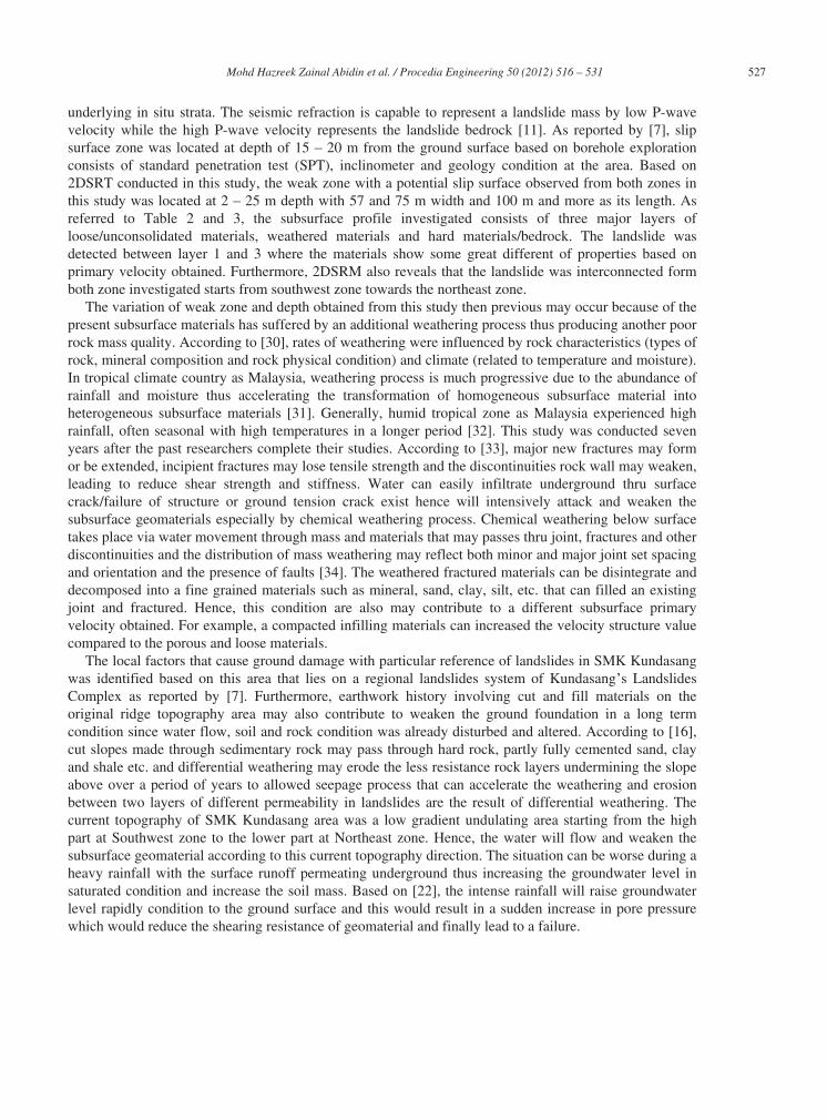
The seismic refraction results conducted were compared and correlated with a previous researcher [7].Comparison was made based on borehole cross section A A and B B as given in Figure 6 andprimary velocities from Table 1. According to [19], [20] and [29], the using concept of seismic refractionin locating weakness plane (slip surface /shear plane) is that the materials above the weakness planeconsist of great difference properties such as a slipped mass will exhibit lower seismic velocity than those
527 Mohd Hazreek Zainal Abidin et al. / Procedia Engineering 50 ( 2012 ) 516 – 531
underlying in situ strata. The seismic refraction is capable to represent a landslide mass by low P-wavevelocity while the high P-wave velocity represents the landslide bedrock [11]. As reported by [7], slipsurface zone was located at depth of 15 20 m from the ground surface based on borehole explorationconsists of standard penetration test (SPT), inclinometer and geology condition at the area. Based on2DSRT conducted in this study, the weak zone with a potential slip surface observed from both zones inthis study was located at 2 25 m depth with 57 and 75 m width and 100 m and more as its length. Asreferred to Table 2 and 3, the subsurface profile investigated consists of three major layers ofloose/unconsolidated materials, weathered materials and hard materials/bedrock. The landslide wasdetected between layer 1 and 3 where the materials show some great different of properties based onprimary velocity obtained. Furthermore, 2DSRM also reveals that the landslide was interconnected formboth zone investigated starts from southwest zone towards the northeast zone.
The variation of weak zone and depth obtained from this study then previous may occur because of thepresent subsurface materials has suffered by an additional weathering process thus producing another poor rock mass quality. According to [30], rates of weathering were influenced by rock characteristics (types of rock, mineral composition and rock physical condition) and climate (related to temperature and moisture).In tropical climate country as Malaysia, weathering process is much progressive due to the abundance ofrainfall and moisture thus accelerating the transformation of homogeneous subsurface material intoheterogeneous subsurface materials [31]. Generally, humid tropical zone as Malaysia experienced highrainfall, often seasonal with high temperatures in a longer period [32]. This study was conducted sevenyears after the past researchers complete their studies. According to [33], major new fractures may formor be extended, incipient fractures may lose tensile strength and the discontinuities rock wall may weaken, leading to reduce shear strength and stiffness. Water can easily infiltrate underground thru surfacecrack/failure of structure or ground tension crack exist hence will intensively attack and weaken thesubsurface geomaterials especially by chemical weathering process. Chemical weathering below surfacetakes place via water movement through mass and materials that may passes thru joint, fractures and other discontinuities and the distribution of mass weathering may reflect both minor and major joint set spacingand orientation and the presence of faults [34]. The weathered fractured materials can be disintegrate anddecomposed into a fine grained materials such as mineral, sand, clay, silt, etc. that can filled an existingjoint and fractured. Hence, this condition are also may contribute to a different subsurface primaryvelocity obtained. For example, a compacted infilling materials can increased the velocity structure valuecompared to the porous and loose materials.
The local factors that cause ground damage with particular reference of landslides in SMK Kundasangwas identified based on this area that lies on a regional landslides system of Kundasang s LandslidesComplex as reported by [7]. Furthermore, earthwork history involving cut and fill materials on theoriginal ridge topography area may also contribute to weaken the ground foundation in a long termcondition since water flow, soil and rock condition was already disturbed and altered. According to [16],cut slopes made through sedimentary rock may pass through hard rock, partly fully cemented sand, clayand shale etc. and differential weathering may erode the less resistance rock layers undermining the slopeabove over a period of years to allowed seepage process that can accelerate the weathering and erosionbetween two layers of different permeability in landslides are the result of differential weathering. Thecurrent topography of SMK Kundasang area was a low gradient undulating area starting from the highpart at Southwest zone to the lower part at Northeast zone. Hence, the water will flow and weaken thesubsurface geomaterial according to this current topography direction. The situation can be worse during a heavy rainfall with the surface runoff permeating underground thus increasing the groundwater level insaturated condition and increase the soil mass. Based on [22], the intense rainfall will raise groundwaterlevel rapidly condition to the ground surface and this would result in a sudden increase in pore pressurewhich would reduce the shearing resistance of geomaterial and finally lead to a failure.

528 Mohd Hazreek Zainal Abidin et al. / Procedia Engineering 50 ( 2012 ) 516 – 531
The effect of geological structure is also regarded as one of the several factors that contribute thedamageability condition in Kundasang area especially during an earthquake. According to [5], the entiredistrict of Kundasang has been exposed to minor earthquake tremor and continuous translatory soilmovement that contributing to frequent landslides in the area. This seismic activity has affected structuralgeology in several areas in Sabah including Kundasang. Kundasang was located at the intersection ofregional fault zone of Quaternary age as reported by [6]. Locally Kundasang is located near to the Lobou-lobou fault line which is considered as a part of the Crocker fault zone in northern segment that intersectwith another regional Mensaban fault zone. According to [6], Lobou-lobou fault segment is a currentlyactive fault with a sinistral displacement. Mass movements in SMK Kundasang can easily be observedthrough ground damage by an existing fault, tension crack and fractured or failure of manmade structure.The Trusmadi rock is one of the unstable geomaterial present identified as one of the root causes ofwidespread and continuous mass movement in Kundasang area by a still rising Kinabalu pluton [35].Borneo Post (2011) also reported that a study conducted by the South East Asia Disaster ProgrammeResearch Institute (SEADPRI) and the Department of Mineral and Geoscience Malaysia alreadyconfirmed that Kundasang has a sensitive, fragile and complex geological system.
4. Conclusions
The problematic subsurface profile in landslides was successfully being investigated using 2D seismicrefraction tomography. The geometry and primary velocity distribution of SMK Kundasang hasdetermined by analyzing seismic refraction data obtained along the NE and SW zones and the result hasshown a good similarity with the borehole data. This finding has proved that this method is able to predict the landslides features in order to assist the conventional borehole data. 2DSRT was successfully mappedthe subsurface profile which able to extend the surface information mapped by geodynamic mapping andother physical mapping. The mechanics and physical characteristics of the landslide can be easilyrecognized. The determination of shape and depth of the subsurface landslide which caused grounddamage are easier and cheaper than with conventional borehole method. The information from therefraction survey was useful for rehabilitation and mitigation purposes such as rippability and excavationworks. This geophysical method is suitable for our sustainable ground investigation since it can reducetime, money and compliment others conventional method especially by its 2D surface technique ofinvestigation. The application of seismic refraction tomography in conjunction with geological andborehole information was effectively being applied for mapping of ground damage with particularreference of near surface landslides.
Acknowledgements
Thank are due to all supervisors and research members for their tremendous guidance, work andcooperation. Many thanks go to Universiti Tun Hussein Onn Malaysia for the sponsor and financialsupport throughout this research activity.
References
[1] Yalcin A. A geotechnical study on the landslides in the Trabzon Province, NE, Turkey. Applied Clay Science 2011;52:11-19.
[2] Israil M, Pachauri AK. Geophysical characterization of a landslide site in the Himalayan foothill region. Journal of Asian
Earth Sciences 2003; 22:253-263.

529 Mohd Hazreek Zainal Abidin et al. / Procedia Engineering 50 ( 2012 ) 516 – 531
[3] Guzzetti F. Landslide fatalities and the evaluation of landslide risk in Italy. Engineering Geology 2000;58:89-107.
[4] McCann DM, & Forster A. Reconnaissance geophysical methods in landslide investigations. Engineering Geology
1990;29:59-78.
[5] Morpi M. Borneo Post - May 7, 2011, Saturday.
[6] Tjia HD. Kundasang (Sabah) at the intersection of regional of Quaternary Age. Bulletin 53 Geological Society of Malaysia
2007;59 66.
[7] Komoo I, Lim CS. Kompleks Gelinciran Tanah Kundasang: Pemetaan Terperinci di Kawasan Sekolah Menengah
Kundasang. Bulletin Geological Society of Malaysia 2003;387 - 392.
[8] Abidin MHZ, Ishak MF, Baharuddin MFT, Zin NSM, Omardin MA. The application of seismic refraction survey for
subsurface profile investigation. Proc. International Conference on Building, Science and Engineering 2009 Johor Bahru Malaysia.
[9] Godio A, Strobbia C, De Bacco G. Geophysical characterisation of a rockslide in an alpine region. Engineering Geology
2006;83:273-286.
[10] Mauritsch HJ, Seiberl W, Arndt R, Römer A, Schneiderbauer K, Sendlhofer GP. Geophysical investigations of large
landslides in the Carnic Region of southern Austria. Engineering Geology 2000;56:373-388.
[11] Göktürkler G, Balkaya Ç, Erhan Z. Geophysical investigation of a landslide: The Alt nda landslide site, zmir (western
Turkey). Journal of Applied Geophysics 2008;65:84-96.
[12] Hack R. Geophysics for slope stability. Surveys in Geophysics 2000;21:423-448.
[13] Bogoslovsky VA, Ogilvy AA. Geophysical methods for the investigation of landslides. International Journal of Rock
Mechanics and Mining Sciences & amp; Geomechanics Abstracts 1978;15:562 571.
[14] Cummings D, Clark BR. Use of seismic refraction and electrical resistivity surveys in landslides investigations. Bulletin
Association of Engineering Geologists 1988;Vol. XXV,No. 4:459-464.
[15] Palmer DF, Weisgarber SL, Geophysical survey of the Stump Basin Landslide, Ohio. Bulletin Association of Engineering
Geologist 1988;Vol. XXV, No. 3:363-370.
[16] Cornforth DH. Landslides in Practice: Investigation, Analysis and Remedial/Preventative Option in Soils, New Jersey: John
Wiley & Sons, Inc.;2005.
[17] Ferrucci F, Amelio M, Sorriso-Valvo M, Tansi C. Seismic prospecting of a slope affected by deep-seated gravitational
slope deformation: the Lago Sackung, Calabria, Italy. Engineering Geology 2000;57:53-64.
[18] Kim MI, Kim JS, Kim NW, Jeong GC. Surface geophysical investigations of landslide at the Wiri area in southeastern
Korea. Environmental Earth Sciences 2011;63:999-1009.
[19] Al-Saigh N, Al-Dabbagh T. Identification of landslide slip-surface and its shear strength: A new application for shallow
seismic refraction method. Journal of the Geological Society of India 2010;76:175-180.
[20] Glade T, Stark P, Dikau R. Determination of potential landslide shear plane depth using seismic refraction a case study in
Rheinhessen, Germany. Bulletin of Engineering Geology and the Environment 2005;64:151-158.
[21] Clayton CRI, Matthews MC, Simons NE. Site Investigation, 2nd ed. Oxford; Blackwell Science: 1995.
[22] Lee TS. Slope Stability and Stabilization Methods, 2nd ed. New York; John Wiley & Sons, Inc.: 2002.
[23] Liu C, Evett JB, Soils and Foundations. 7th ed. Jurong; Pearson: 2008.
[24] Jacobson G. Gunung Kinabalu Area, Sabah, Malaysia. Geological Survey Malaysia Report 8, 1970;118.
[25] Hutchinson CS, Bergman SC, Graves JE. A Miocene collisional belt in North Borneo: uplift mechanism and isostatic
adjustment quantified by termochronology. Journal of Geological Society London 2000;157:783-793.
[26] Burger HR, Sheehan AF, Jones CH. Introduction to Applied Geophysics: Exploring the Shallow Subsurface. New York. W.
W. Norton & Company; 2006.
[27] McCarthy DF. Essentials of Soil Mechanics and Foundations: Basic Geotechnics. 7th ed. New Jersey; Pearson
International Edition: 2007.
[28] Peck RB, Hanson WE, Thornburn TH. Foundation Engineering. New York; Wiley: 1974.
[29] Caris JPT, Van Asch TWJ. Geophysical, geotechnical and hydrological investigations of a small landslide in the French
Alps. Engineering Geology 1991;31:249-276.
[30] Lutgens FK, Tarbuck EJ. Essentials of Geology. 9th ed. New Jersey; Pearson International Edition: 2006.

530 Mohd Hazreek Zainal Abidin et al. / Procedia Engineering 50 ( 2012 ) 516 – 531
[31] Abidin MH, Saad R, Ahmad F, Wijeyesekera DC, Baharuddin MFT. Integral analysis of geoelectrical (resistivity) and
geotechnical (SPT) data in slope stability assessment. International Journal of Arts and Sciences 2012.
[32] Saunders MK, Fookes PG. A review of the relationship of rock weathering and climate and its significance to foundation
engineering. Engineering Geology 1970;4:289-325.
[33] Dearman W, Price D, Martin R, Pinches G, Fookes PG. The description and classification of weathered rocks for
engineering purposes. The Quarterly Journal of Engineering Geology 1995:212.
[34] Currey DT. Deeply weathered rock at Victorian dam sites. Engineering Geology 1977.
[35] Tjia HD, Root causes of extensive mass movements around Mount Kinabalu, Southeast Asia s Summit. Proc. 8th Fieldwise
Seminar and 3rd International Symposium on Geological Engineering Education, Gadjah Mada University, Yogyakarta, Indonesia
2006.

531 Mohd Hazreek Zainal Abidin et al. / Procedia Engineering 50 ( 2012 ) 516 – 531
Appendix
Fig. 7. Location of spread line (SL) in SMK Kundasang Sabah, Malaysia
Fig. 8. Location of spread line conducted with some of the geodynamic mapping in SMK Kundasang Sabah, Malaysia [7]
A
B