seismic response of reinforced concrete silos for … · model ii is the reinforced concrete silo...
TRANSCRIPT

486
Available online through - http://ijifr.com/searchjournal.aspx Accepted After Review On: October 22, 2015
Published On: October 24, 2015
International Journal of Informative & Futuristic Research
ISSN: 2347-1697 Volume 3 Issue 2 October 2015
Abstract
Silos are the stack-like structures that are more commonly used for bulk storage of grain, coal, cement, carbon black, woodchips, food products and sawdust. As the density, flow and friction properties of stored material vary, the loads applied on silo structure and associated load carrying system also vary. In this paper reinforced concrete silo supported with shear walls and supported on only columns are considered with same dimensions. These two silos are modeled using Finite Element Method package software SAP 2000.These are molded for the soil type II situated in the zone II when silo is empty, partially filled and fully filled with storage material. These models are analysed for load combination 1.2 (DL+IL±EL) for both X and Y direction according to IS 1893 (Part-I) : 2002 and then response of reinforced concrete silo with shear wall and without shear walls has been determined in terms of Lateral displacement. The results reveal the effect of stored material on non-linear seismic behavior of Reinforced Concrete Silo.
1. Introduction
Silos are used for storing different types of granular as well as powdery materials which are
subjected to many different unconventional loading conditions which result in unusual failure
modes. Silo failure have alerted design engineers to the danger of designing silos for only static
pressures due to stored material at rest. Those failures have inspired wide spread research into the
variation of pressures and flow materials into the Silo. The silo is designed according IS 1893 (Part-
I): 2002 considering clinker as the storage material.
2. Modelling And Analysis
In this present study a friendly user FEM software package SAP 2000 is used. Here two reinforced
concrete silo models with only columns and with shear wall are considered when the Silo is fully
Seismic Response Of Reinforced Concrete Silos
For Loading Combination 1.2 (DL+IL±EL) Paper ID IJIFR/ V3/ E2/ 042 Page No. 486-492 Research Area Civil Engineering
Index Terms Silo, Clinker, FEM, EQx, EQy
Rajani S Togarsi
Assistant Professor
Department of Civil Engineering
KLS Gogte Institute of Technology
Belagavi, Karnataka, India

487
ISSN: 2347-1697 International Journal of Informative & Futuristic Research (IJIFR)
Volume - 3, Issue -2, October 2015 Continuous 26th Edition, Page No.:486-492
Rajani S Togarsi:: Seismic Response Of Reinforced Concrete Silos For Loading Combination 1.2 (DL+IL±EL)
filled with storage material. Clinker is considered as granular storage material with density 16.50
kN/ m3. Gravity load analysis and lateral load analysis is carried out as per the seismic code 1893
(Part I): 2002 are carried out for both reinforced concrete silo models and an effort is made to study
the effect of seismic load on them. Design data considered for the Silo are
given in appendix. The silo consists of 1) Cylindrical wall, hopper bottom, curved beams on top and
bottom, columns and 2) Cylindrical wall, hopper bottom, curved beams on top and bottom,
columns with shear wall. Cylindrical walls are modeled as shell element. Columns and curved
beams provided at top and bottom are modeled as frame element. Curved beams are modeled as
rigid diaphragms. The beam column joints are assumed to be rigid.
In this dissertation two distinct models of silo are considered are shown in fig 1 and 2.
MODEL I - Reinforced Concrete Silo elevated on Columns.
MODEL II - Reinforced Concrete Silo elevated on Shear Wall.
Model I is the Reinforced Concrete Silo model elevated on columns in which silo walls are
modeled as shell element and 8 columns are provided each at a radial distance of 45o of length 9 m.
A Plinth beam is provided at 1m above the ground surface to provide connectivity between the
columns. Model II is the Reinforced Concrete Silo model elevated on Shear wall. In this model silo
Figure 1: Reinforced Concrete Silo
supported on columns only (MODEL I)
Figure 2: Reinforced Concrete Silo supported on
columns with shear walls (MODEL II)
488
ISSN: 2347-1697 International Journal of Informative & Futuristic Research (IJIFR)
Volume - 3, Issue -2, October 2015 Continuous 26th Edition, Page No.:486-492
Rajani S Togarsi:: Seismic Response Of Reinforced Concrete Silos For Loading Combination 1.2 (DL+IL±EL)
walls as well as shear walls are modeled as shell element and 8 columns are provided each at a
radial distance of 45o of length 9 m.
A Plinth beam is provided at the base to provide connectivity between the columns and shear walls.
Four Shear walls are provided along with the columns alternatively along the radial direction.
Clinker is considered as storage material and live load acting due to storage material is calculated
manually and applied uniformly along the height of the silo. A detail of shell elements and frame
elements considered for the model making is given in Appendix.
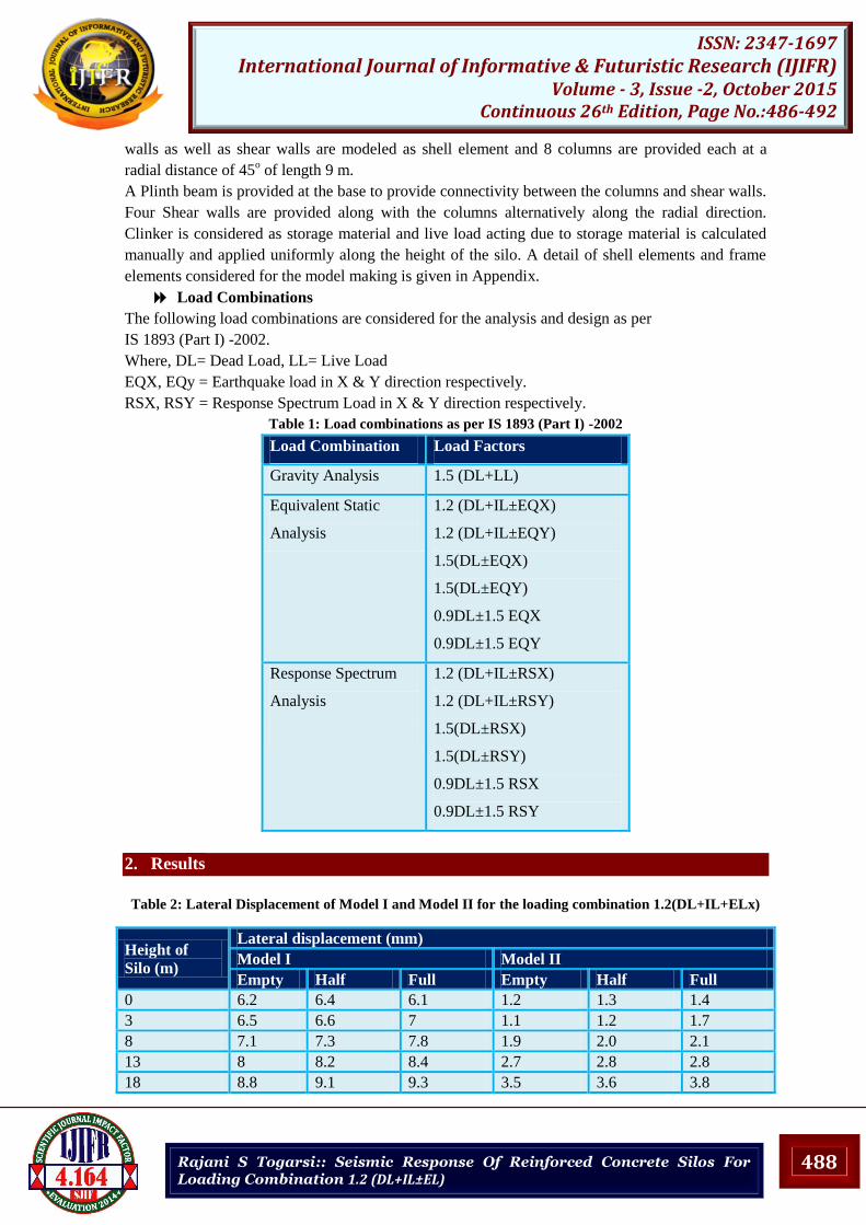
Load Combinations
The following load combinations are considered for the analysis and design as per
IS 1893 (Part I) -2002.
Where, DL= Dead Load, LL= Live Load
EQX, EQy = Earthquake load in X & Y direction respectively.
RSX, RSY = Response Spectrum Load in X & Y direction respectively.
Table 1: Load combinations as per IS 1893 (Part I) -2002
Load Combination Load Factors
Gravity Analysis 1.5 (DL+LL)
Equivalent Static
Analysis
1.2 (DL+IL±EQX)
1.2 (DL+IL±EQY)
1.5(DL±EQX)
1.5(DL±EQY)
0.9DL±1.5 EQX
0.9DL±1.5 EQY
Response Spectrum
Analysis
1.2 (DL+IL±RSX)
1.2 (DL+IL±RSY)
1.5(DL±RSX)
1.5(DL±RSY)
0.9DL±1.5 RSX
0.9DL±1.5 RSY
2. Results
Table 2: Lateral Displacement of Model I and Model II for the loading combination 1.2(DL+IL+ELx)
Height of
Silo (m)
Lateral displacement (mm)
Model I Model II
Empty Half Full Empty Half Full
0 6.2 6.4 6.1 1.2 1.3 1.4
3 6.5 6.6 7 1.1 1.2 1.7
8 7.1 7.3 7.8 1.9 2.0 2.1
13 8 8.2 8.4 2.7 2.8 2.8
18 8.8 9.1 9.3 3.5 3.6 3.8

489
ISSN: 2347-1697 International Journal of Informative & Futuristic Research (IJIFR)
Volume - 3, Issue -2, October 2015 Continuous 26th Edition, Page No.:486-492
Rajani S Togarsi:: Seismic Response Of Reinforced Concrete Silos For Loading Combination 1.2 (DL+IL±EL)
Figure 3: Lateral Displacement of Model I and Model II for loading 1.2(DL+IL+ELx)
Table 3 Lateral Displacement of Model I and Model II for loading 1.2(DL+IL+ELy)
Height of
Silo (m)
Lateral displacement (mm)
Model I Model II
Empty Half Full Empty Half Full
0 3.1 3.2 3.3 0.3 0.3 0.4
3 3.3 3.6 3.7 0.5 0.6 0.7
8 3.6 4.2 4.3 0.7 0.9 1.1
13 3.9 4.9 5.0 1.2 1.3 1.6
18 4.2 5.6 5.8 1.7 1.8 2.1
Figure 4: Lateral Displacement of Model I and Model II for loading 1.2(DL+IL+ELy)
490
ISSN: 2347-1697 International Journal of Informative & Futuristic Research (IJIFR)
Volume - 3, Issue -2, October 2015 Continuous 26th Edition, Page No.:486-492
Rajani S Togarsi:: Seismic Response Of Reinforced Concrete Silos For Loading Combination 1.2 (DL+IL±EL)
From the Table 3, Figure 3 it is observed that the lateral displacement is observed to be more on the
top of the silo and decreases at the bottom for both the models I & II. We can also observe that the
provision of shear wall decreases the deformation from 6.2 mm to 1.2mm for empty filling
condition. Similarly, from the table 3 and Fig 4 it is observed that the lateral displacement is
observed to be more on the top of the silo and decreases at the bottom for both the model I & II.
4. Conclusions
In this study the seismic behavior of reinforced concrete silo supported on shear walls and
supported on only columns were analysed for empty, partially filled and fully filled filling
conditions. The seismic response of reinforced concrete silo is determined in the form of lateral
displacement and were analysed and compared for silo supported on staging with and without shear
walls. Lateral displacement increases with increase in mass and stiffness. Silo with full filled
materials experiences high Lateral displacement than Silo with half-filled storage material or empty
silo. Silo supported on shear wall experiences less Lateral displacement than Silo supported on only
columns. Lateral displacement increases with increase in mass and stiffness. Silo with full filled
materials experiences high Lateral displacement than Silo with half-filled storage material or empty
silo. Silo supported on shear wall experiences less Lateral displacement than Silo supported on only
columns.
5. Scope For Future Work
The study may further be carried out for Soil Structure Interaction effect.
The study may be considered for Silo with only one opening for the movement of vehicles.
The study may be carried out for other types of Silos and bunkers with different wall
thickness.
6. References
[1] [1] Adem Dogangun, Zeki Karaca, Ahmet Durmus and Halil Sezen (2009), Cause of Damage and
Failures in Silo Structures, Journal of Performance of Constructed Facilities, Vol.23, No. 2, pp ( 65-71).
[2] [2] Alnabuddin L.V. & Sohrbuddin Ahmad, (1995), Design Forces and Moments in Circular Silos
Based on Finite Element Package, Journal of the Civil Engineering division, The Institution of Engineers,
Bangladesh, Vol CE23, pp (59-88).
[3] [3] Bradely M S, Berrey R.G. and Farnis R.J.(2007), Methods for design of Hoppers, Silos, Bunkers &
Bins for reliable gravity Flow for Pharmaceutical, Food, Mineral and Other applications,The Wolfson
Centre of Bulk solids Handling Technology,University of Greenwich,UK, pp ( 213-220).
[4] [4] Carson J. W, Phd and. Jenkyn R.T, (1993), Load Development and Structural
[5] [5] Flat Tinis and Faith Bazman, (2006) Stiffening of Thin Cylindrical Silo Shell against Buckling
Loads, The 12th International Conference On Machine Design & Production8, Turkey, pp (05-08).
[6] [6] Gabriel Perez, (2008),Numerical simulations in granular matter :The discharge of a 2D silo, Indian
Academy of Sciences,Vol. 70, No. 6, . 989-1007, journal of June, pp (989-1007).
[7] [7] Jofriet J. C. and Kleywegt H. S. (1980) , Design Criteria For Hoops Of Concrete
[8] [8] Stave Silos, School of Engineering, Universityof Guelph, Guelph, Ontario NIG 2W1, Can. Agric.
Eng. 22,pp ( 9-13).
[9] [9] John W. Carson and Tracy, (200),Silo Failures: Why Do They Happen?, One Technology Drive,
Westford, MA, USA, Vol.4, pp ( 499-512).
[10] [10] Mohmed T. Abdel-Fattah, Ian D.Moore, and Tarek T.Abdel-Fattah, (2006) Behavior of elevated
concrete Silos filled with saturated Solids, NRC Research Press Web, Vol. 227, pp (33-239)
[11] [11] Nateghi F and Yakhchalian M (2012) Seismic Behavior of Silos with Different Height to Diameter
Ratios Considering Granular Material-structure Interaction, Structural Engineering Research Center, Iran,
Vol. 25, No. 1, pp ( 26-37).

491
ISSN: 2347-1697 International Journal of Informative & Futuristic Research (IJIFR)
Volume - 3, Issue -2, October 2015 Continuous 26th Edition, Page No.:486-492
Rajani S Togarsi:: Seismic Response Of Reinforced Concrete Silos For Loading Combination 1.2 (DL+IL±EL)
APPENDIX
Table A1: Detailed data of the Reinforced Concrete Silo studied
Structure OMRF
Cylindrical Height (H) 15 m
Hopper Bottom Height (h) 5 m
Diameter of Silo (D) 10 m
Diameter of Hopper Bottom (d) 1m
Column Height 8m
Number of Columns 9
Angle between each Column 45o
Height of Shear Wall 9m
Material Properties
Grade of concrete M30
Grade of steel Fe 415
Young’s modulus M30 concrete (E) 27.38 x 10⁶ kN/m2
Density of reinforced concrete 24 kN/m3
Density of Clinker (W) 16.5 kN/m3 (IS 4995 Part 1): 197
Angle of Friction b/w wall and storage material 36o (IS 4995 Part 1): 1974
Coefficient of wall friction (μ) 0.7
Member Properties
Thickness Silo Wall 0.2 m for Cylindrical wall
0.22 m for hopper bottom wall
Top Curved Beam size 0.23m X 0.35m
Bottom Curved Beam size 0.75mX 0.35m
Column Size 0.5m X 0.75m
Table A2: Input data of all the structures for equivalent static analysis
Zone II
Zone factor, Z (Table 2)
IS: 1893 (Part 1 ) -2002 0.10
Importance factor, I (Table 8),
IS: 1893 (Part 4) -2005 1.5
Response reduction factor, R (Table 7),
IS: 1893 (Part 4) -2005 3.0
Damping ratio 5% (for RC framed structure)
Fundamental Natural Period:
As per IS 1893 ( Part 4) -2005, clause: 14.2, The approximate fundamental natural period of
vibration (T) of stack-like structure can be determined by Rayleigh’s approximation for
fundamental mode of vibration as follows in seconds.
The fundamental time period for Stack-Like Structures T is given by
T= CT √ (W t h)/ Es g …………………. ( 5.1)
Where,
CT = Coefficient depending upon the slenderness ratio of the structure given in table 6 of IS 1893
(Part 4),

492
ISSN: 2347-1697 International Journal of Informative & Futuristic Research (IJIFR)
Volume - 3, Issue -2, October 2015 Continuous 26th Edition, Page No.:486-492
Rajani S Togarsi:: Seismic Response Of Reinforced Concrete Silos For Loading Combination 1.2 (DL+IL±EL)
Wt = Total weight of the structure including weight of lining contents above base,
h = Height of the structure above base
Es = Modulus of elasticity of material of structural life
A = Area of cross section at the base of the structural shell
g = acceleration due to gravity
√
∑ ( )
∑
= weight lumped at ith location with the weights applied simultaneously with the force
applied horizontally
= Lateral static deflection under its own lumped weight at ith location
N = number of locations of lumped weight and
g = acceleration due to gravity
For Medium Soil Sites:
{
}
Design Horizontal Seismic Coefficient, Ah;
Ah =
Ah =
= 0.0625
Design Seismic Base Shear
VB =Ah xW
VB = 0.0625 X 30217.50 = 2015.50
Vertical Distribution of Base Shear to Different Floor Levels;
The design base shear VB computed is distributed along the height of the building as per
following
Expressions
∑