selecting and sizing exhaust hoods
TRANSCRIPT
Improving Commercia
Selecting &
This design guide provides informa-tion that will help achieve optimum performance and energy efficiency in commercial kitchen ventilation sys-tems by properly selecting and sizing exhaust hoods. The information pre-sented is applicable to new construc-tion and, in many instances, retrofit construction. The audience for this guideline is kitchen designers, me-chanical engineers, code officials, food service operators, property man-agers, and maintenance people. This guide is intended to augment compre-hensive design information published in the Kitchen Ventilation Chapter in the ASHRAE Handbook on HVAC Applications, as well as Design Guide 2: Improving Commercial Kitchen Ventilation System Performance – Optimizing Makeup Air (previously published in 2002 by the California Energy Commission under the title Improving Commercial Kitchen Venti-lation Performance). This guide reviews the fundamentals of kitchen exhaust, describes the de-sign process from the perspective of exhaust hood application and con-cludes with real-world design exam-ples illustrating the potential for en-ergy efficient design.
F
h
c
a
W
t
m
t
(
T
h
g
s
B
t
F
b
o
a
p
w
g
r
a
o
a
The Design Process
Design Guide 1 l Kitchen Ventilation System Performance
Sizing Exhaust Hoods
undamentals of Kitchen Exhaust Hot air rises! An exhaust fan in the ceiling could remove much of the
eat produced by cooking equipment. But mix in smoke, volatile organic
ompounds, grease particles and vapor from cooking, and a means to capture
nd contain the effluent becomes necessary to avoid health and fire hazards.
hile an exhaust hood serves that purpose, the key question becomes: what is
he appropriate exhaust rate? The answer always depends on several factors: the
enu of food products and the type (and use) of the cooking equipment under
he hood, the style and geometry of the hood itself, and how the makeup air
conditioned or otherwise) is introduced into the kitchen.
he Cooking Factor Cooking appliances are categorized as light-, medium-, heavy-, and extra
eavy-duty, depending on the strength of the thermal plume and the quantity of
rease, smoke, heat, water vapor, and combustion products produced. The
trength of the thermal plume is a major factor in determining the exhaust rate.
y their nature, these thermal plumes rise by natural convection, but they are
urbulent and different cooking processes have different “surge” characteristics.
or example, the plume from hamburger cooking is strongest when flipping the
urgers. Ovens and pressure fryers may have very little plume until they are
pened to remove food product. Open flame, non-thermostatically controlled
ppliances, such as underfired broilers and open top ranges, exhibit strong steady
lumes. Thermostatically controlled appliances, such as griddles and fryers have
eaker plumes that fluctuate in sequence with thermostat cycling (particularly
as-fired equipment). As the plume rises, it should be captured by the hood and
emoved by the suction of the exhaust fan. Air in the proximity of the appliances
nd hood moves in to replace it. This replacement air, which must ultimately
riginate as outside air, is referred to as makeup air.
Fundamentals of Kitchen Exhaust 1
The Cooking Factor 1
The Hood Factor 2
The Makeup Air Factor 6
The Design Process 7
QSR Design Example A-1
Casual Dining Example B-1
Building codes distinguish between cooking processes that create smoke
nd grease (e.g., frying, griddling, or charbroiling) and those that produce only
Fundamentals of Kitchen Exhaust
heat and moisture (e.g., dishwashing and some baking and steaming operations).
Cooking that produces smoke and grease requires liquid-tight construction with
a built-in fire suppression system (Type I hood), while operations that produce
only heat and moisture do not require liquid-tight construction or a fire sup-
pression system (Type II hood).
Menu items may produce more or less smoke and grease depending on
their fat content and how they are cooked. Higher fat content foods tend to re-
lease more smoke and grease regardless of the type of cooking process. Testing
under an ASHRAE sponsored research project at the University of Minnesota
confirmed that hamburger cooked on a charbroiler releases finer smoke parti-
cles and more grease vapor and particles than hamburger cooked on a griddle.
The percentage fat content of hamburger also contributes to differences in the
amount of grease and smoke released in cooking. Chicken breast, which has
less fat compared to hamburger, releases less particulate and less grease during
cooking on a charbroiler or on a griddle compared to hamburger.
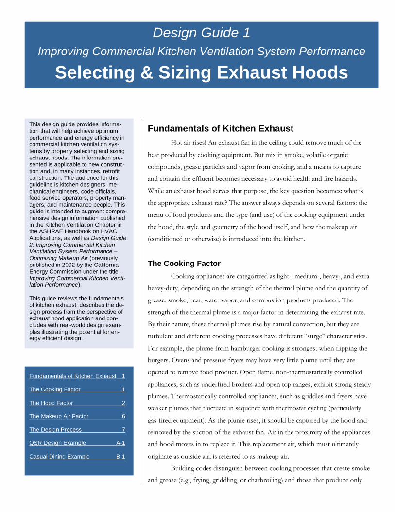
The Hood Factor The design exhaust rate also depends on the hood style and construc-
tion features. Wall-mounted canopy hoods, island (single or double) canopy
hoods, and proximity (backshelf, pass-over, or eyebrow) hoods all have differ-
ent capture areas and are mounted at different heights and horizontal positions
relative to the cooking equipment (see Figure 1). Generally, for the identical
(thermal plume) challenge, a single-island canopy hood requires more exhaust
than a wall-mounted canopy hood, and a wall-mounted canopy hood requires
more exhaust than a proximity (backshelf) hood. The performance of a double-
island canopy tends to emulate the performance of two back-to-back wall-
canopy hoods, although the lack of a physical barrier between the two hood
sections makes the configuration more susceptible to cross drafts.
Building Codes Historically the United States had three organizations that drafted model building codes which were adopted by local ju-risdictions as law. These organizations sponsored development of standardized building codes, usually called “model building codes”, to assure better code uniformity within the three regions in which they evolved. In the northeast US, the Building Officials Council Association sponsored the National Building Code. In the southeast US, the Southern Build-ing Code Council International, spon-sored the Standard Building Code. In western US, the International Council of Building Code Officials sponsored the Uniform Building Code. California juris-dictions adopted the UBC, including the Uniform Mechanical Code (UMC). In 1994 these organizations formed the International Code Council to unify their codes. In 2000, the first full edition of the International Building Code (IBC) was published. In 2000, the National Fire Protection Association (NFPA) announced that it would sponsor a complete building code that would be an alternative to the IBC. In 2002, NFPA published its first edition. Mechanical code requirements for kitchen ventilation are similar among these model codes. Unlisted Hoods must meet the prescrip-tive materials and design requirements of the local building and health codes. In addition they must be operated at ex-haust rates dictated by the local building code. Listed Hoods have been tested against a recognized standard, such as Under-writers Laboratories (UL) Standard 710. Standard 710 dictates materials and design requirements similar to those in the building code and it has a perform-ance test requirement for capture and containment of the thermal plume. Building codes also require Type I hoods (liquid-tight construction with a built-in fire suppression system) over cooking operations which produce smoke and grease. requires Cooking operations that produce only heat and moisture require a Type II hood (liquid-tight construction and a fire suppression system are not required).
Design Guide 1 – Selecting and Sizing Exhaust Hoods – 03.15.04 2
Fundamentals of Kitchen Exhaust
Design Guide 1 – Selecting and Sizin
y
Figure 1. Styles of Exhaus
Wall Mounted Canop
g Exhaust Hoods – 03.15.04
f
t Hoods.
A note of caution: Although a wel
applied with success at very low exhaust rate
medium-duty equipment), this same style of
formance data and/or in accordance with m
ted by code) may fail to effectively capture an
exhaust rates of 300 cfm/ft or more. Figure
ineffective applications of proximity hoods.
Single Island Canopy
Double Island Canopyl-engin
s (e.g.,
hood (
aximum
d con
2 illust
Eyebrow
Back Shel Pass Over3
eered proximity hood can be
150 cfm per linear foot over
if specified without per-
height and setback permit-
tain the cooking effluent at
rates relatively effective and

Fundamentals of Kitchen Exhaust
Design Guide 1 – Selecting and Sizing Exhaust Hoods – 03.15.04 4
Figure 2. Proximity Hood Effective Design Ineffective Design
Building and/or health codes typically provide basic construction and
materials requirements for exhaust hoods, as well as prescriptive exhaust rates
based on appliance duty and length of the hood (cfm per linear ft.) or open face
area of the hood (cfm per ft2). Codes usually recognize exceptions for hoods
that have been tested against a recognized standard, such as Underwriters Labo-
ratories (UL) Standard 710. Part of the UL standard is a “cooking smoke and
flair up” test. This test is essentially a cooking effluent capture and containment
(C&C) test where “no evidence of smoke or flame escaping outside the exhaust
hood” must be observed. Hoods bearing a recognized laboratory mark are
called listed hoods, while those constructed to the prescriptive requirements of
the building code are called unlisted hoods. Generally, an off-the-shelf listed hood
can be operated at a lower exhaust rate than an unlisted hood of comparable style
and size over the same cook line. Lower exhaust rates may be proven by labora-
tory testing with specific hood(s) and appliance lineup using the test protocol
described in ASTM Standard F-1704, Test Method for Performance of Commercial
Kitchen Ventilation Systems. This process is sometimes referred to as “custom-
engineering” a hood.
Laboratory testing of different combinations of appliances has demon-
strated that minimum capture and containment rates vary significantly due to
appliance type and position under the hood. For example a heavy-duty appli-
ance at the end of a hood is more prone to spillage than the same appliance lo-
cated in the middle of the hood.

Fundamentals of Kitchen Exhaust
Design Guide 1 – Selecting and Sizing Exhaust Hoods – 03.15.04 5
Side Panels and Overhang Side (or end) panels (as represented in Figure 3) permit a reduced ex-
haust rate in most cases, as all of the replacement air is drawn across the front
of the equipment, which improves containment of the effluent plume generated
by the hot equipment. They are a relatively inexpensive way to improve C&C
and reduce the total exhaust rate. Another benefit of end panels is to mitigate
the negative effect that cross drafts can have on hood performance. It is impor-
tant to know that partial side panels can provide almost the same benefit as full
panels. Although tending to defy its definition as an “island” canopy, end panels
can improve the performance of a double-island or single-island canopy hood.
An increase in overhang should improve the ability of a canopy hood
to capture because of the increased distance between the plume and hood
edges. This may be accomplished by pushing the appliances as far back under a
canopy hood as practical and/or by increasing the side length. Although this
improves C&C performance, for unlisted hoods under a local jurisdiction refer-
encing the Uniform Mechanical Code (UMC), this would require increase in the
code-required exhaust rate. Larger overhangs are recommended for appliances
that create plume surges, such as convection and combination ovens, steamers
and pressure fryers. This was the driving argument for converting the code-
specified exhaust rates from a “cfm/ft2” to a “cfm/linear ft.” basis in the cur-
rent edition of the International Mechanical Code (IMC). Figure 3. Illustration of partial and full side panels.
Hood Geometry The ability of a hood to capture and contain cooking effluent can often
be enhanced by adding passive features (e.g., angles, flanges, or geometric flow
deflectors) or active features (e.g., low-flow, high-velocity jets) along the edges
of the hood or within the hood reservoir. Such design features can improve
hood performance dramatically over a basic box-style hood with the same
nominal dimensions.
Cross Drafts Cross drafts can have a detrimental affect on all hood/appliance com-
binations. Cross-drafts affect island canopy hoods more than wall mounted
canopy hoods because they have more open area allowing drafts to push or pull
effluent from the hood. For example, a pedestal fan used by staff for additional
cooling can severely degrade hood performance, may make capture impossible,
Fundamentals of Kitchen Exhaust
Design Guide 1 – Selecting and Sizing Exhaust Hoods – 03.15.04 6
and may spill the plume into the kitchen. Location of delivery doors, service
doors, pass-through openings and drive-through windows may be sources of
cross drafts due to external and internal air pressure differences. Cross drafts
can also be developed when the makeup air system is not working correctly,
causing air to be pulled from open drive-through windows or doors.
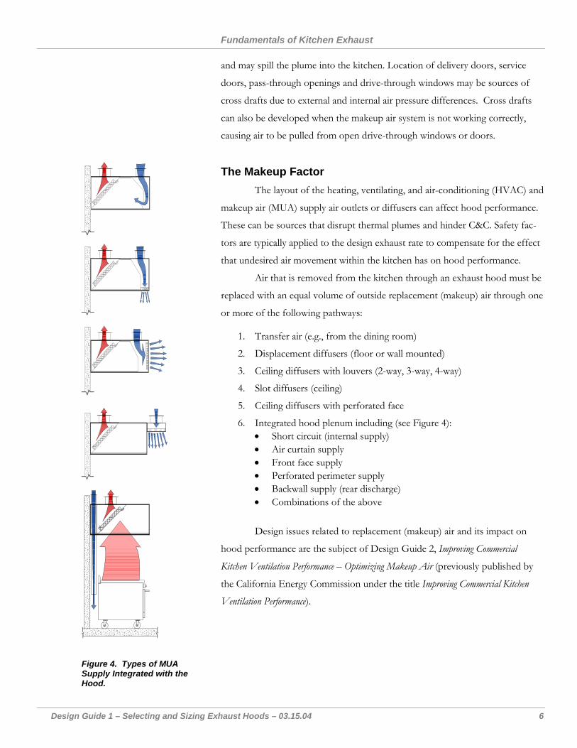
The Makeup Factor The layout of the heating, ventilating, and air-conditioning (HVAC) and
makeup air (MUA) supply air outlets or diffusers can affect hood performance.
These can be sources that disrupt thermal plumes and hinder C&C. Safety fac-
tors are typically applied to the design exhaust rate to compensate for the effect
that undesired air movement within the kitchen has on hood performance.
Air that is removed from the kitchen through an exhaust hood must be
replaced with an equal volume of outside replacement (makeup) air through one
or more of the following pathways:
1. Transfer air (e.g., from the dining room)
2. Displacement diffusers (floor or wall mounted)
3. Ceiling diffusers with louvers (2-way, 3-way, 4-way)
4. Slot diffusers (ceiling)
5. Ceiling diffusers with perforated face
6. Integrated hood plenum including (see Figure 4): • Short circuit (internal supply) • Air curtain supply • Front face supply • Perforated perimeter supply • Backwall supply (rear discharge) • Combinations of the above
Design issues related to replacement (makeup) air and its impact on
hood performance are the subject of Design Guide 2, Improving Commercial
Kitchen Ventilation Performance – Optimizing Makeup Air (previously published by
the California Energy Commission under the title Improving Commercial Kitchen
Ventilation Performance).
Figure 4. Types of MUA Supply Integrated with the Hood.
Design Guide 1 – Selecting and Sizing Exhaust Hoods – 03.15.04 7
The Design Process Successfully applying the fundamentals of commercial kitchen ventila-
tion (CKV) during the design process requires a good understanding of the local
building code requirements, the menu and appliance preferences, and the pro-
ject’s budget. Information about the kitchen equipment and ventilation re-
quirements may evolve over the course of the design phase. Data needed by
other members of the design team may require early estimates of certain pa-
rameters (e.g., the amount of exhaust and makeup air, motor horsepower, water
supply and wastewater flow rates). As more decisions are made, new informa-
tion may allow (or require) refinements to the design that affect exhaust and
makeup air requirements.
The fundamental steps in the design of a CKV system are:
1. Establish location and “duty” classifications of appliances including menu effects. Determine (or coordinate with foodservice consult-ant) preferred appliance layout for optimum exhaust ventilation.
2. Select hood type, style, and features.
3. Size exhaust airflow rate.
4. Select makeup air strategy; size airflow and layout diffusers.
Steps 1 through 3 are discussed in this Design Guide; Step 4 is the subject of
Design Guide 2, Improving Commercial Kitchen Ventilation Performance – Optimizing
Makeup Air.
A good understanding of how building code requirements apply to
kitchen design is essential. Local or state building codes are usually based on
one of the “model” building codes promulgated by national code organizations
(see sidebar). Our discussion of the building codes will be limited to require-
ments that affect design exhaust and makeup air rates, which are usually found
in the mechanical code portion of the overall building code.
Historically, codes and test standards used “temperature” ratings for
classifying cooking equipment. Although these temperature ratings roughly cor-
related with the ventilation requirement of the appliances, there were many gray
areas. During development of ASHRAE Standard 154, Ventilation for Com-
mercial Cooking Appliances, it was recognized that plume strength, which takes
into account plume volume and surge characteristics, as well as plume tempera-
ture, would be a better measure for rating appliances for application in building
codes. “Duty” ratings were created for the majority of commercial cooking ap-
pliances under Standard 154, and these were recently adopted by the Interna-
The Design Process
Design Guide 1 – Exhaust Hood Selection and Sizing – 03.15.04 8
tional Mechanical Code (IMC). The Kitchen Ventilation chapter of the
ASHRAE Applications Handbook (2003 edition) applied the same concept to
establish ranges of exhaust rates for listed hoods. The appended Design Exam-
ples in this Guide reference duty classifications for appliances. The duty classifi-
cations listed in the sidebar are from ASHRAE Standard 154-2003, Ventilation
for Commercial Cooking Operations.
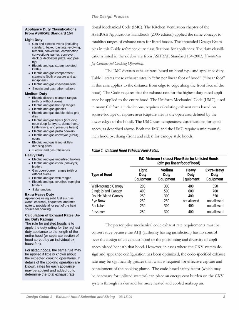
Appliance Duty Classifications From ASHRAE Standard 154
Light Duty • Gas and electric ovens (including
standard, bake, roasting, revolving, retherm, convection, combination convection/steamer, conveyor, deck or deck-style pizza, and pas-try)
• Electric and gas steam-jacketed kettles
• Electric and gas compartment steamers (both pressure and at-mospheric)
• Electric and gas cheesemelters • Electric and gas rethermalizers
Medium Duty • Electric discrete element ranges
(with or without oven) • Electric and gas hot-top ranges • Electric and gas griddles • Electric and gas double-sided grid-
dles • Electric and gas fryers (including
open deep-fat fryers, donut fryers, kettle fryers, and pressure fryers)
• Electric and gas pasta cookers • Electric and gas conveyor (pizza)
ovens • Electric and gas tilting skillets
/braising pans • Electric and gas rotisseries
Heavy Duty • Electric and gas underfired broilers • Electric and gas chain (conveyor)
broilers • Gas open-burner ranges (with or
without oven) • Electric and gas wok ranges • Electric and gas overfired (upright)
broilers • Salamanders
Extra Heavy Duty Appliances using solid fuel such as wood, charcoal, briquettes, and mes-quite to provide all or part of the heat source for cooking.
Calculation of Exhaust Rates Us-ing Duty Ratings The rule for unlisted hoods is to apply the duty rating for the highest duty appliance to the length of the entire hood (or separate section of hood served by an individual ex-haust fan).
For listed hoods, the same rule may be applied if little is known about the expected cooking operations. If details of the cooking operation are known, rates for each appliance may be applied and added up to determine the total exhaust rate.
The IMC dictates exhaust rates based on hood type and appliance duty.
Table 1 states these exhaust rates in “cfm per linear foot of hood” (“linear foot”
in this case applies to the distance from edge to edge along the front face of the
hood). The Code requires that the exhaust rate for the highest duty-rated appli-
ance be applied to the entire hood. The Uniform Mechanical Code (UMC), used
in many California jurisdictions, requires calculating exhaust rates based on
square-footage of capture area (capture area is the open area defined by the
lower edges of the hood). The UMC uses temperature classifications for appli-
ances, as described above. Both the IMC and the UMC require a minimum 6-
inch hood overhang (front and sides) for canopy style hoods.
Table 1. Unlisted Hood Exhaust Flow Rates.
IMC Minimum Exhaust Flow Rate for Unlisted Hoods (cfm per linear foot of hood)
Type of Hood Light Duty
Equipment
Medium Duty
Equipment
Heavy Duty
Equipment
Extra-Heavy Duty
Equipment
Wall-mounted Canopy 200 300 400 550 Single Island Canopy 400 500 600 700 Double Island Canopy 250 300 400 550 Eye Brow 250 250 not allowed not allowed Backshelf 250 300 400 not allowed Passover 250 300 400 not allowed
The prescriptive mechanical code exhaust rate requirements must be
conservative because the AHJ (authority having jurisdiction) has no control
over the design of an exhaust hood or the positioning and diversity of appli-
ances placed beneath that hood. However, in cases where the CKV system de-
sign and appliance configuration has been optimized, the code-specified exhaust
rate may be significantly greater than what is required for effective capture and
containment of the cooking plume. The code-based safety factor (which may
be necessary for unlisted systems) can place an energy cost burden on the CKV
system through its demand for more heated and cooled makeup air.
The Design Process
Design Guide 1 – Exhaust Hood Selection and Sizing – 03.15.04 9
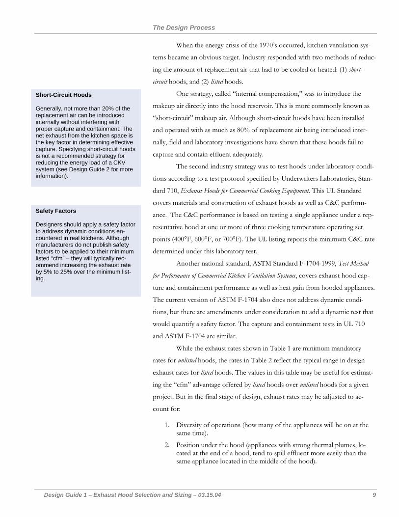
When the energy crisis of the 1970’s occurred, kitchen ventilation sys-
tems became an obvious target. Industry responded with two methods of reduc-
ing the amount of replacement air that had to be cooled or heated: (1) short-
circuit hoods, and (2) listed hoods.
One strategy, called “internal compensation,” was to introduce the
makeup air directly into the hood reservoir. This is more commonly known as
“short-circuit” makeup air. Although short-circuit hoods have been installed
and operated with as much as 80% of replacement air being introduced inter-
nally, field and laboratory investigations have shown that these hoods fail to
capture and contain effluent adequately.
Short-Circuit Hoods Generally, not more than 20% of the replacement air can be introduced internally without interfering with proper capture and containment. The net exhaust from the kitchen space is the key factor in determining effective capture. Specifying short-circuit hoods is not a recommended strategy for reducing the energy load of a CKV system (see Design Guide 2 for more information).
The second industry strategy was to test hoods under laboratory condi-
tions according to a test protocol specified by Underwriters Laboratories, Stan-
dard 710, Exhaust Hoods for Commercial Cooking Equipment. This UL Standard
covers materials and construction of exhaust hoods as well as C&C perform-
ance. The C&C performance is based on testing a single appliance under a rep-
resentative hood at one or more of three cooking temperature operating set
points (400°F, 600°F, or 700°F). The UL listing reports the minimum C&C rate
determined under this laboratory test.
Safety Factors Designers should apply a safety factor to address dynamic conditions en-countered in real kitchens. Although manufacturers do not publish safety factors to be applied to their minimum listed “cfm” – they will typically rec-ommend increasing the exhaust rate by 5% to 25% over the minimum list-ing.
Another national standard, ASTM Standard F-1704-1999, Test Method
for Performance of Commercial Kitchen Ventilation Systems, covers exhaust hood cap-
ture and containment performance as well as heat gain from hooded appliances.
The current version of ASTM F-1704 also does not address dynamic condi-
tions, but there are amendments under consideration to add a dynamic test that
would quantify a safety factor. The capture and containment tests in UL 710
and ASTM F-1704 are similar.
While the exhaust rates shown in Table 1 are minimum mandatory
rates for unlisted hoods, the rates in Table 2 reflect the typical range in design
exhaust rates for listed hoods. The values in this table may be useful for estimat-
ing the “cfm” advantage offered by listed hoods over unlisted hoods for a given
project. But in the final stage of design, exhaust rates may be adjusted to ac-
count for:
1. Diversity of operations (how many of the appliances will be on at the same time).
2. Position under the hood (appliances with strong thermal plumes, lo-cated at the end of a hood, tend to spill effluent more easily than the same appliance located in the middle of the hood).
The Design Process
Design Guide 1 – Exhaust Hood Selection and Sizing – 03.15.04 10
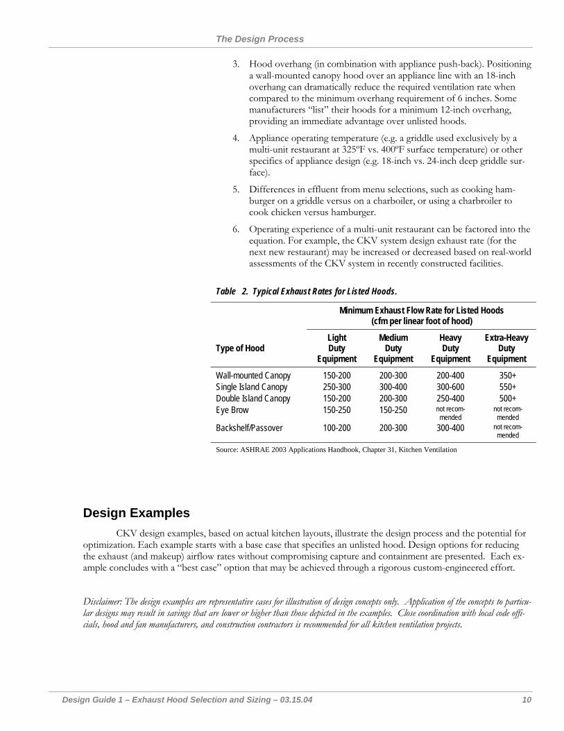
3. Hood overhang (in combination with appliance push-back). Positioning a wall-mounted canopy hood over an appliance line with an 18-inch overhang can dramatically reduce the required ventilation rate when compared to the minimum overhang requirement of 6 inches. Some manufacturers “list” their hoods for a minimum 12-inch overhang, providing an immediate advantage over unlisted hoods.
4. Appliance operating temperature (e.g. a griddle used exclusively by a multi-unit restaurant at 325ºF vs. 400ºF surface temperature) or other specifics of appliance design (e.g. 18-inch vs. 24-inch deep griddle sur-face).
5. Differences in effluent from menu selections, such as cooking ham-burger on a griddle versus on a charboiler, or using a charbroiler to cook chicken versus hamburger.
6. Operating experience of a multi-unit restaurant can be factored into the equation. For example, the CKV system design exhaust rate (for the next new restaurant) may be increased or decreased based on real-world assessments of the CKV system in recently constructed facilities.
Table 2. Typical Exhaust Rates for Listed Hoods.
Minimum Exhaust Flow Rate for Listed Hoods (cfm per linear foot of hood)
Type of Hood Light Duty
Equipment
Medium Duty
Equipment
Heavy Duty
Equipment
Extra-Heavy Duty
Equipment
Wall-mounted Canopy 150-200 200-300 200-400 350+ Single Island Canopy 250-300 300-400 300-600 550+ Double Island Canopy 150-200 200-300 250-400 500+ Eye Brow 150-250 150-250 not recom-
mended not recom-
mended Backshelf/Passover 100-200 200-300 300-400 not recom-
mended Source: ASHRAE 2003 Applications Handbook, Chapter 31, Kitchen Ventilation
Design Examples CKV design examples, based on actual kitchen layouts, illustrate the design process and the potential for
optimization. Each example starts with a base case that specifies an unlisted hood. Design options for reducing the exhaust (and makeup) airflow rates without compromising capture and containment are presented. Each ex-ample concludes with a “best case” option that may be achieved through a rigorous custom-engineered effort.
Disclaimer: The design examples are representative cases for illustration of design concepts only. Application of the concepts to particu-lar designs may result in savings that are lower or higher than those depicted in the examples. Close coordination with local code offi-cials, hood and fan manufacturers, and construction contractors is recommended for all kitchen ventilation projects.
Design Guide 1 – Example A – 03.15.04 A-1
Design Example A: Quick Service Restaurant A quick serve restaurant (QSR) has the appliances listed in Table A-1. As in most quick-service restaurants,
kitchen space is at a premium and the limited menu is prepared using a few primary appliances.
Table A-1. Duty Rating and Lengths of Appliances.
Appliances (left to right under hood) Appliance
Rated Input (kBtu/h)
Appliance Duty Rating
(per IMC)
Active Cooking Length (Ft)
Hood Front Face Length (Ft)
Overhang (6-inches) 0.00 0.50 Two (2) Deep Fat Fryers (80 kBtu/h each) 160 Medium 2.50 2.50 Fryer Drip Station 0.00 1.25 4-foot Griddle 80 Medium 4.00 4.00 Half-Size Convection Oven 35 Light 2.50 2.50 Overhang (6-inches) 0.00 0.50
Total 275 9.00 11.25
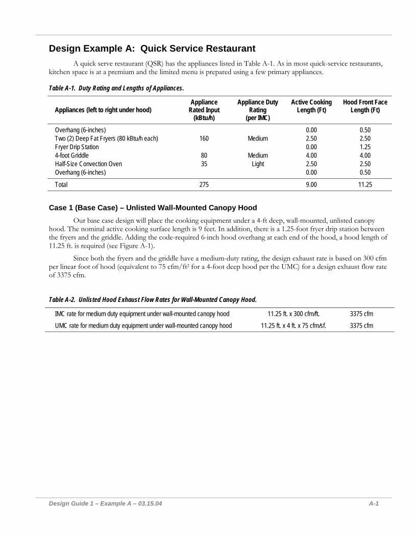
Case 1 (Base Case) – Unlisted Wall-Mounted Canopy Hood Our base case design will place the cooking equipment under a 4-ft deep, wall-mounted, unlisted canopy
hood. The nominal active cooking surface length is 9 feet. In addition, there is a 1.25-foot fryer drip station between the fryers and the griddle. Adding the code-required 6-inch hood overhang at each end of the hood, a hood length of 11.25 ft. is required (see Figure A-1).
Since both the fryers and the griddle have a medium-duty rating, the design exhaust rate is based on 300 cfm per linear foot of hood (equivalent to 75 cfm/ft2 for a 4-foot deep hood per the UMC) for a design exhaust flow rate of 3375 cfm.
Table A-2. Unlisted Hood Exhaust Flow Rates for Wall-Mounted Canopy Hood.
IMC rate for medium duty equipment under wall-mounted canopy hood 11.25 ft. x 300 cfm/ft. 3375 cfm
UMC rate for medium duty equipment under wall-mounted canopy hood 11.25 ft. x 4 ft. x 75 cfm/sf. 3375 cfm
Design Example A: Quick Service Restaurant
Design Guide 1 – Example A – 03.15.04 A-2
11.25 ft
Figure A-1. Base Case - Unlisted Wall-Mounted Canopy Hood.
Design Example A: Quick Service Restaurant
Design Guide 1 – Example A – 03.15.04 A-3
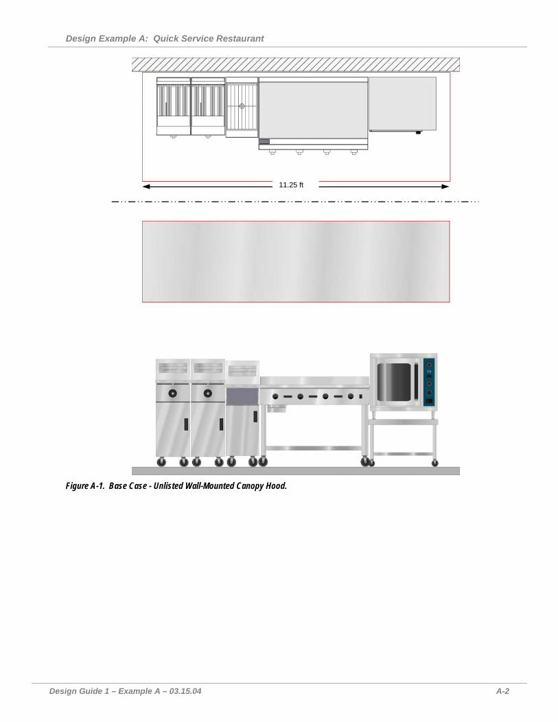
Case 2: Application of a Listed Canopy Hood In this second design scenario, the unlisted canopy hood is replaced with a listed canopy hood that will per-
mit selecting an exhaust airflow rate below the prescriptive code value. In addition (following coordination with the owner and operations manager), the fryer dump station is moved to the end of the line (partially under the hood), while a full-size end panel is added to the oven-end of the hood. This reduces the hood length from 11.25 ft. to 9.5 ft. For listed hoods, the exhaust rate is also established by the highest appliance duty, which in this case is set by either the fryer and griddle as medium duty. Based on its own testing and experience with the selected hood and the pro-posed cookline, the manufacturer recommends a design ventilation rate of 250 cfm per linear foot of hood. Note that if the hood length were not reduced, the required exhaust rate would be about 440 cfm greater, or 2815 cfm.
Table A-4. Listed Wall-Mounted Canopy Hood Exhaust Flow Rates.
UL Listed Canopy hood @ 250 cfm/ft 9.5 ft x 250 cfm/ft 2375 cfm
9.5 ft
Figure A-2. Case 2 - Listed Wall-Mounted Canopy Hood with End Panel.
Design Example A: Quick Service Restaurant
Design Guide 1 – Example A – 03.15.04 A-4
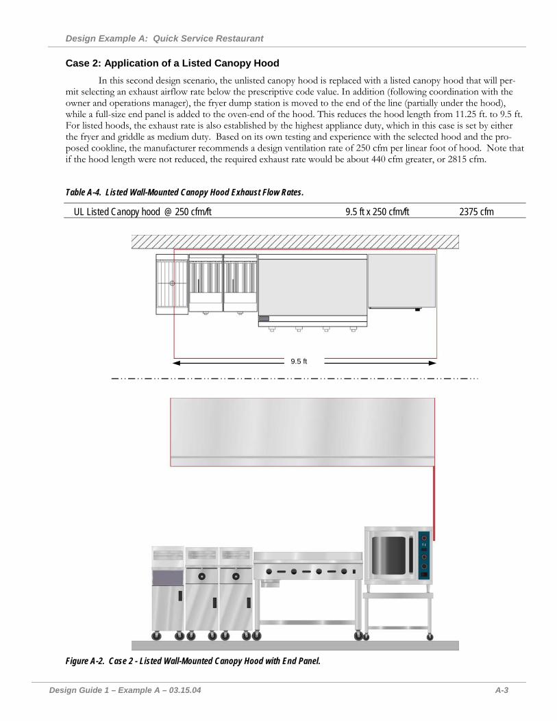
Case 3: Optimized Design Using a Listed Backshelf and Canopy Hood Capitalizing on the design practice of larger QSR operators, the canopy hood over the fryers and griddle is
replaced with a listed backshelf hood. Within its listing for this hood, the manufacturer recommends an exhaust rate of 150 cfm per linear ft. for medium duty equipment. Since this backshelf hood incorporates integrated side panels (in accordance with its listing), the fryer dump station can be moved completely outside of the hood footprint and the hood length is reduced to 9 feet. A custom canopy hood with full side panels serves the convection oven, again at the manufacturer’s recommended exhaust rate of 150 cfm per linear ft. The exhaust rates in this example would require laboratory verification in accordance with ASTM F1704-99.
2.5
6.5
Figure A-3. Case 3 - Optimized Design with a Listed Backshelf Hood and a Listed Canopy Hood. Table A-5. Listed Backshelf and Canopy Hood Exhaust Flow Rates.
Listed canopy hood w/full side panels 2.5 ft. x 150 cfm/ft. 375 cfm Listed backshelf hood with side panels 6.5 ft. x 150 cfm/ft. 975 cfm Total Exhaust Rate 1350 cfm
Design Example A: Quick Service Restaurant
Design Guide 1 – Example A – 03.15.04 A-5
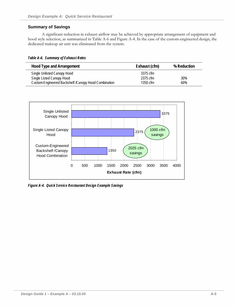
Summary of Savings A significant reduction in exhaust airflow may be achieved by appropriate arrangement of equipment and
hood style selection, as summarized in Table A-6 and Figure A-4. In the case of the custom-engineered design, the dedicated makeup air unit was eliminated from the system.
Table A-6. Summary of Exhaust Rates
Hood Type and Arrangement Exhaust (cfm) % Reduction Single Unlisted Canopy Hood 3375 cfm Single Listed Canopy Hood 2375 cfm 30% Custom-Engineered Backshelf /Canopy Hood Combination 1350 cfm 60%
1350
2375
3375
0 500 1000 1500 2000 2500 3000 3500 4000
Custom-EngineeredBackshelf /CanopyHood Combination
Single Listed CanopyHood
Single UnlistedCanopy Hood
Exhaust Rate (cfm)
1000 cfm savings
2025 cfm savings
Figure A-4. Quick Service Restaurant Design Example Savings

Design Guide 1 – Example B – 03.15.04 B-1
Design Example B: Casual Dining Restaurant A casual dining restaurant will have the appliances listed in Table B-1. Figure B-1 shows the proposed layout.
Table B-1. Duty Rating and Lengths of Appliances.
Appliances (left to right under hood) Typical Rated Input
(kBtu/h) Typical IMC Appli-ance Duty Rating
Active Cooking Length (Ft)
Front Face Length (Ft)
Overhang (6-in– over 1-ft Counter) 0.5 6-foot Griddle 120 Medium 6 6 3-foot Charbroiler 96 Heavy 3 3 Fryer Drip Station 1.25 Three (3) Fryers (80 kBtu/h each) 240 Medium 3.75 3.75 Prep Surface 1 4-burner Open Range Top 80 Heavy 2 2 Overhang (6-in) 0.5
Totals 536 14.75 18.0
18 ft
Figure B-1. Base Case Appliance Layout.
Design Example B: Casual Dining Restaurant
Design Guide 1 – Example B – 03.15.04 B-2
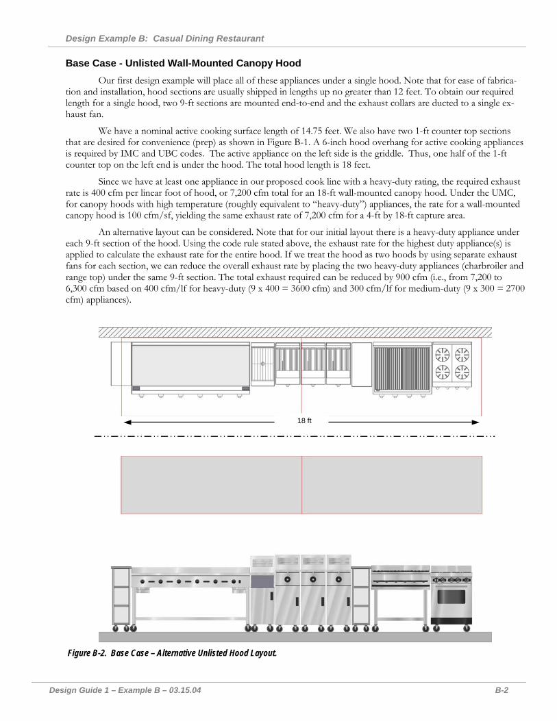
Base Case - Unlisted Wall-Mounted Canopy Hood Our first design example will place all of these appliances under a single hood. Note that for ease of fabrica-
tion and installation, hood sections are usually shipped in lengths up no greater than 12 feet. To obtain our required length for a single hood, two 9-ft sections are mounted end-to-end and the exhaust collars are ducted to a single ex-haust fan.
We have a nominal active cooking surface length of 14.75 feet. We also have two 1-ft counter top sections that are desired for convenience (prep) as shown in Figure B-1. A 6-inch hood overhang for active cooking appliances is required by IMC and UBC codes. The active appliance on the left side is the griddle. Thus, one half of the 1-ft counter top on the left end is under the hood. The total hood length is 18 feet.
Since we have at least one appliance in our proposed cook line with a heavy-duty rating, the required exhaust rate is 400 cfm per linear foot of hood, or 7,200 cfm total for an 18-ft wall-mounted canopy hood. Under the UMC, for canopy hoods with high temperature (roughly equivalent to “heavy-duty”) appliances, the rate for a wall-mounted canopy hood is 100 cfm/sf, yielding the same exhaust rate of 7,200 cfm for a 4-ft by 18-ft capture area.
An alternative layout can be considered. Note that for our initial layout there is a heavy-duty appliance under each 9-ft section of the hood. Using the code rule stated above, the exhaust rate for the highest duty appliance(s) is applied to calculate the exhaust rate for the entire hood. If we treat the hood as two hoods by using separate exhaust fans for each section, we can reduce the overall exhaust rate by placing the two heavy-duty appliances (charbroiler and range top) under the same 9-ft section. The total exhaust required can be reduced by 900 cfm (i.e., from 7,200 to 6,300 cfm based on 400 cfm/lf for heavy-duty (9 x 400 = 3600 cfm) and 300 cfm/lf for medium-duty (9 x 300 = 2700 cfm) appliances).
18 ft
Figure B-2. Base Case – Alternative Unlisted Hood Layout.
Design Example B: Casual Dining Restaurant
Design Guide 1 – Example B – 03.15.04 B-3
Table B-2. Unlisted Wall-Mounted Canopy Hood Exhaust Flow Rates.
Base Case: Single Unlisted Wall-Mounted Canopy Hood IMC, Heavy Duty Equipment: 18 ft. x 400 cfm/ft. 7,200 cfm UMC, High Temperature Equipment: 18 ft. x 4 ft. x 100 cfm/ft2. 7,200 cfm
Alternative Layout Case: Two Unlisted Wall-Mounted Canopy Hood IMC, Heavy Duty Equipment: 9 ft. x 400 cfm/ft. 3,600 cfm IMC, Medium Duty Equipment: 9 ft. x 300 cfm/ft. 2,700 cfm Total for Alternative Layout under the IMC: 6,300 cfm UMC, High Temperature Equipment: 9 ft. x 4 ft. x 100 cfm/ft2. 3,600 cfm UMC, Medium Temperature Equipment: 9 ft. x 4 ft. x 75 cfm/ft2. 2,700 cfm Total for Alternative Layout under the UBC: 6,300 cfm
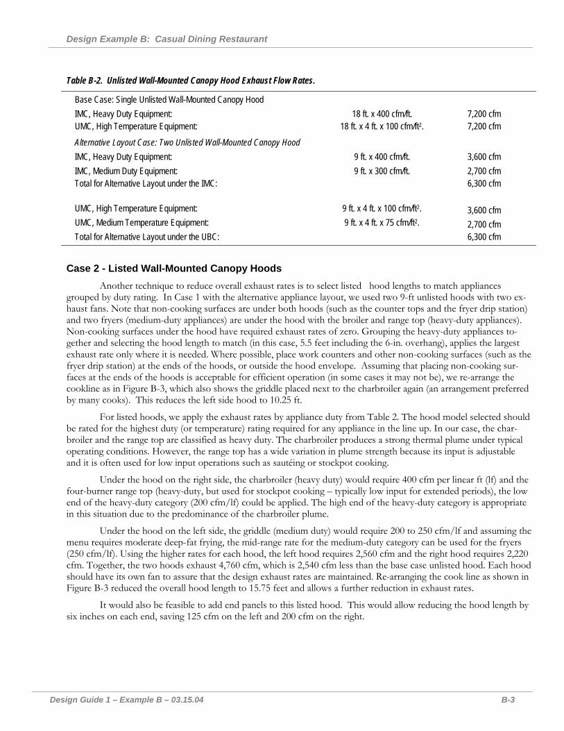
Case 2 - Listed Wall-Mounted Canopy Hoods Another technique to reduce overall exhaust rates is to select listed hood lengths to match appliances
grouped by duty rating. In Case 1 with the alternative appliance layout, we used two 9-ft unlisted hoods with two ex-haust fans. Note that non-cooking surfaces are under both hoods (such as the counter tops and the fryer drip station) and two fryers (medium-duty appliances) are under the hood with the broiler and range top (heavy-duty appliances). Non-cooking surfaces under the hood have required exhaust rates of zero. Grouping the heavy-duty appliances to-gether and selecting the hood length to match (in this case, 5.5 feet including the 6-in. overhang), applies the largest exhaust rate only where it is needed. Where possible, place work counters and other non-cooking surfaces (such as the fryer drip station) at the ends of the hoods, or outside the hood envelope. Assuming that placing non-cooking sur-faces at the ends of the hoods is acceptable for efficient operation (in some cases it may not be), we re-arrange the cookline as in Figure B-3, which also shows the griddle placed next to the charbroiler again (an arrangement preferred by many cooks). This reduces the left side hood to 10.25 ft.
For listed hoods, we apply the exhaust rates by appliance duty from Table 2. The hood model selected should be rated for the highest duty (or temperature) rating required for any appliance in the line up. In our case, the char-broiler and the range top are classified as heavy duty. The charbroiler produces a strong thermal plume under typical operating conditions. However, the range top has a wide variation in plume strength because its input is adjustable and it is often used for low input operations such as sautéing or stockpot cooking.
Under the hood on the right side, the charbroiler (heavy duty) would require 400 cfm per linear ft (lf) and the four-burner range top (heavy-duty, but used for stockpot cooking – typically low input for extended periods), the low end of the heavy-duty category (200 cfm/lf) could be applied. The high end of the heavy-duty category is appropriate in this situation due to the predominance of the charbroiler plume.
Under the hood on the left side, the griddle (medium duty) would require 200 to 250 cfm/lf and assuming the menu requires moderate deep-fat frying, the mid-range rate for the medium-duty category can be used for the fryers (250 cfm/lf). Using the higher rates for each hood, the left hood requires 2,560 cfm and the right hood requires 2,220 cfm. Together, the two hoods exhaust 4,760 cfm, which is 2,540 cfm less than the base case unlisted hood. Each hood should have its own fan to assure that the design exhaust rates are maintained. Re-arranging the cook line as shown in Figure B-3 reduced the overall hood length to 15.75 feet and allows a further reduction in exhaust rates.
It would also be feasible to add end panels to this listed hood. This would allow reducing the hood length by six inches on each end, saving 125 cfm on the left and 200 cfm on the right.
Design Example B: Casual Dining Restaurant
Design Guide 1 – Example B – 03.15.04 B-4
5.5 ft 10.25 ft
Figure B-3. Revised Layout with Two Listed Hoods.
Table B-4. Revised Layout with Listed Wall-Mounted Canopy Hood Exhaust Flow Rates.
Hood over griddle & fryers: 10.25 ft. x 250 cfm/ft. 2,560 cfm Hood over broiler & range: 5.5 ft. x 400 cfm/ft. 2,200 cfm Total Exhaust Rate: 4,760 cfm
Case 3 – Optimized Design - Combination Backshelf/Canopy
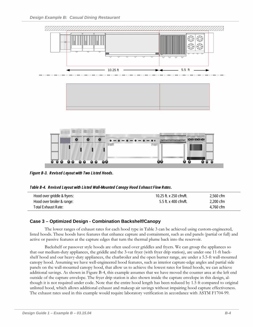
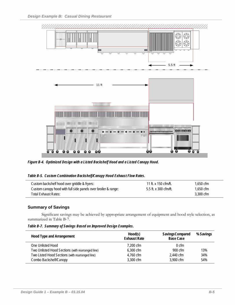
The lower ranges of exhaust rates for each hood type in Table 3 can be achieved using custom-engineered, listed hoods. These hoods have features that enhance capture and containment, such as end panels (partial or full) and active or passive features at the capture edges that turn the thermal plume back into the reservoir.
Backshelf or passover style hoods are often used over griddles and fryers. We can group the appliances so that our medium-duty appliances, the griddle and the 3-vat fryer (with fryer drip station), are under one 11-ft back-shelf hood and our heavy-duty appliances, the charbroiler and the open burner range, are under a 5.5-ft wall-mounted canopy hood. Assuming we have well-engineered hood features, such as interior capture-edge angles and partial side panels on the wall-mounted canopy hood, that allow us to achieve the lowest rates for listed hoods, we can achieve additional savings. As shown in Figure B-4, this example assumes that we have moved the counter area at the left end outside of the capture envelope. The fryer drip station is also shown inside the capture envelope in this design, al-though it is not required under code. Note that the entire hood length has been reduced by 1.5 ft compared to original unlisted hood, which allows additional exhaust and makeup air savings without impairing hood capture effectiveness. The exhaust rates used in this example would require laboratory verification in accordance with ASTM F1704-99.
Design Example B: Casual Dining Restaurant
Design Guide 1 – Example B – 03.15.04 B-5
5.5 ft
11 ft
Figure B-4. Optimized Design with a Listed Backshelf Hood and a Listed Canopy Hood.
Table B-5. Custom Combination Backshelf/Canopy Hood Exhaust Flow Rates.
Custom backshelf hood over griddle & fryers: 11 ft. x 150 cfm/ft. 1,650 cfm Custom canopy hood with full side panels over broiler & range: 5.5 ft. x 300 cfm/ft. 1,650 cfm Total Exhaust Rates: 3,300 cfm
Summary of Savings Significant savings may be achieved by appropriate arrangement of equipment and hood style selection, as
summarized in Table B-7.
Table B-7. Summary of Savings Based on Improved Design Examples.
Hood Type and Arrangement Hood(s) Exhaust Rate
SavingsCompared Base Case
% Savings
One Unlisted Hood 7,200 cfm 0 cfm Two Unlisted Hood Sections (with rearranged line) 6,300 cfm 900 cfm 13% Two Listed Hood Sections (with rearranged line) 4,760 cfm 2,440 cfm 34% Combo Backshelf/Canopy 3,300 cfm 3,900 cfm 54%

Design Guide 1 – Acknowledgements – 03.15.04 C-1
Notes and Acknowledgments
Funding Southern California Edison P.O. Box 6400 Rancho Cucamonga, CA 91729 (800) 990-7788 www.sce.com/showcasing-energy-efficiency
This Guide is funded by California utility cus-tomers and administered by Southern California Edison under the auspices of the California Public Utilities Commission
Research Team Architectural Energy Corporation 2540 Frontier Ave, Suite 201 Boulder, CO 80301 (800) 450-4454 www.archenergy.com
Fisher Nickel, inc. 12949 Alcosta Boulevard, Suite 101 San Ramon, CA 94583 (925) 838-7561 www.fishnick.com
Research Labs Commercial Kitchen Ventilation Laboratory 955 North Lively Blvd. Wood Dale, IL 60191 (630) 860-1439 www.archenergy.com/ckv
Food Service Technology Center 12949 Alcosta Boulevard, Suite 101 San Ramon, CA 94583 (925) 866-2864 www.pge.com/fstc
© 2004 by Southern California Edison. Permission is granted to reproduce this document in its entirely provided that this copyright notice is included.