selecting the correct fan - rocky mountain...
TRANSCRIPT

1
Selecting the Correct Fan
Ryan B. JohnsonAir Purification CompanySales EngineerMember, ASHRAEPikes Peak Chapter

2
Your Speakercirca 1998
• Fan Types– Applications– Performance Characteristics
• Fan Construction– Drive Arrangements– Fan Rotation and Discharge– Fan Class of Construction– Spark Resistant Construction– Special Coatings and Materials
• Fan Selection Considerations– Motors– V-belt Drives– Air Volume Control

3
• Centrifugal– Backward Inclined Airfoil-blade – Backward Inclined Flat-blade– Forward Curved Blade– Radial Blade– Radial Tip
• Axial– Propeller / Panel Fan– Tubeaxial– Vaneaxial
• Special Designs– Power Roof Ventilators– Tubular Inline Centrifugal– Mixed Flow
Basic Fan / Wheel Types
4
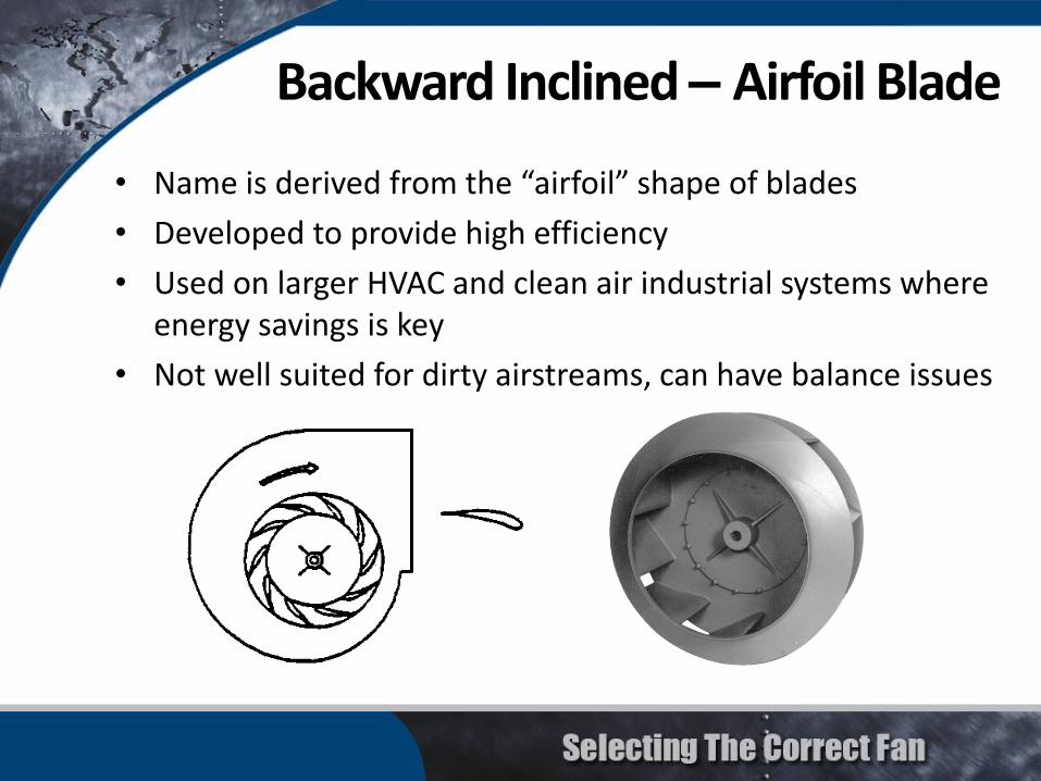
• Name is derived from the “airfoil” shape of blades
• Developed to provide high efficiency
• Used on larger HVAC and clean air industrial systems where energy savings is key
• Not well suited for dirty airstreams, can have balance issues
Backward Inclined – Airfoil Blade
5
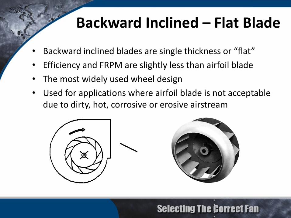
• Backward inclined blades are single thickness or “flat”
• Efficiency and FRPM are slightly less than airfoil blade
• The most widely used wheel design
• Used for applications where airfoil blade is not acceptable due to dirty, hot, corrosive or erosive airstream
Backward Inclined – Flat Blade

6
• Stable performance characteristic
• Non-overloading power curve
• High volume at moderate pressure
• Low abrasion resistance
• High efficiency
• Low noise
Backward Inclined – Flat & Airfoil

7
• Blades are curved forward in the direction of rotation
• Less efficient than airfoil or flat blade designs
• Requires the lowest speed of any centrifugal to move a given amount of air
• Used for low pressure HVAC systems
Forward Curved Blade

8
• OVERLOADING power curve
• Must be properly applied to avoid unstable operation
• Clean air and high temperature applications
• Higher volume at low pressure
• Small size for a given volume
Forward Curved Blade
9
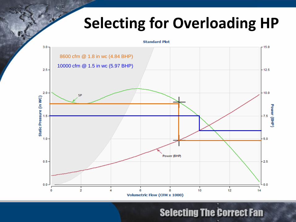
Selecting for Overloading HP
8600 cfm @ 1.8 in wc (4.84 BHP)
10000 cfm @ 1.5 in wc (5.97 BHP)

10
• Blades are flat and “radial” to the fan shaft
• Generally the least efficient of the centrifugal fans
• Material handling and moderate to high pressure industrial applications
Radial Blade

11
• OVERLOADING power curve
• Material handling, self cleaning
• Suitable for dirty airstream, high pressure, high temperature and corrosive applications
• Low volume at high pressure
• Moderate efficiency
• Easy to maintain
Radial Blade

12
• Similar to backward inclined near the hub, but gradually slope towards the direction of wheel rotation ending in a radial direction at the blade tip
• More efficient than the true radial blade
• Designed for wear resistance in mildly erosive air streams
Radial Tip

13
• Adjustable / fixed pitch cast aluminum
• Stamped / extruded aluminum
• Fabricated / die formed steel
• Polymer / composite
• Almost limitless number of configurations
Common Propeller Types

14
• One of the most basic fan designs
• Low pressure, high volume applications
• Designed for ventilation through a wall
• Ring fan design offers slightly higher pressure
Propeller or Panel Fan

15
Propeller panel fans are best utilized near free air
Propeller or Panel Fan

16
Air Flow
• More efficient than the panel fan • Cylindrical housing fits closely to outside diameter of
blade tips• Low to medium pressure ducted industrial and
commercial HVAC systems
Tubeaxial Fan

17
Performance curve sometimes includes a dip to the left of peak pressure which should be avoided
Tubeaxial Fan

18
• Highest efficiency propeller axial fan• Cylindrical housing fits very closely to outside diameter of
blade tips• Straightening vanes allow for greater efficiency and
pressure capabilities• For medium to high pressure HVAC systems
Straightening Vanes
Air Flow
Vaneaxial Fan

19
• More compact than centrifugal fans of same duty• Aerodynamic stall causes the performance curve to dip to
the left of peak pressure which should be avoided
Vaneaxial Fan

20
• Spun aluminum fans for roof mounted exhaust applications
• Upblast or downblast configurations
• Available with our without discharge dampers
• Can utilize centrifugal wheels, props or mixed flow impellers
Specialized Adaptations

21
• Offers tremendous flexibility for inlet and discharge in a AHU application
• Works better than a housed centrifugal for high flows and low SP
• Wall clearance rules must be followed to avoid significant system effect losses
Plenum/Plug Fan
Housed vs. plenum fan

22
• Wheel is generally an airfoil or backward inclined type
• Housing does not fit close to outer diameter of wheel
• For low and medium pressure HVAC systems or industrial applications when an inline housing is geometrically more convenient than a centrifugal configuration
Airflow
Inline Centrifugal Fan

23
• Cylindrical housing is similar to an inline centrifugal
• High volume advantages of axial propeller
• Low sound, high efficiency advantages of tubular centrifugal
Mixed Flow Fan

24
The required flow and pressure may control the style of fan used
Pressure
Flow
Centrifugal
Axial
Typical Application Range

25
• Drive Arrangements
• Fan Rotation and Discharge
• Fan Class of Construction
• Spark Resistant Construction
• Special Coatings and Materials
Fan Construction

26
Arrangement 10 SWSI• Belt drive• Impeller overhung• Two bearings with motor mounted inside base
Drive Arrangements for Centrifugal Fans

27
Arrangement 9 SWSI• Belt drive• Impeller overhung• Two bearings with motor mounted outside base
Drive Arrangements for Centrifugal Fans

28
Arrangement 1 SWSI• Belt drive• Impeller overhung• Two bearings on base• Motor mounted beside fan, typically on a common base
Drive Arrangements for Centrifugal Fans

29
Arrangement 4 SWSI• Direct drive• Impeller overhung on prime
mover shaft• No fan shaft / bearings• Motor base mounted or
integrally directly connected
Drive Arrangements for Centrifugal Fans

30
Arrangement 8 SWSI• Direct drive• Arrangement 1 plus extended base for motor• Motor coupled to fan shaft
Drive Arrangements for Centrifugal Fans
31
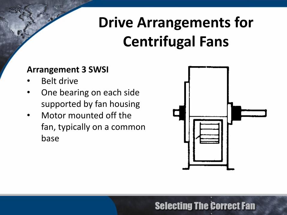
Arrangement 3 SWSI• Belt drive• One bearing on each side
supported by fan housing• Motor mounted off the
fan, typically on a common base
Drive Arrangements for Centrifugal Fans

32
Drive Arrangements for Centrifugal Fans
Arrangement 3 DWDI• For belt drive (or direct) connection• One bearing on each side and supported by fan housing• Motor mounted beside fan, typically on a common base

33
Arrangement 7 SWSI• For direct drive connection• Arrangement 3 plus base
for motor• Motor coupled to fan shaft
Drive Arrangements for Centrifugal Fans

34
Arrangement 7 DWDI• For direct drive connection• Arrangement 3 plus base
for motor• Motor coupled to fan shaft
Drive Arrangements for Centrifugal Fans
35
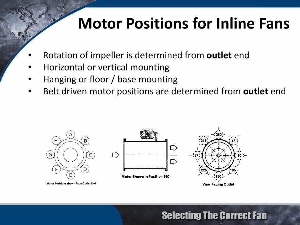
• Rotation of impeller is determined from outlet end• Horizontal or vertical mounting• Hanging or floor / base mounting• Belt driven motor positions are determined from outlet end
Motor Positions for Inline Fans

36
Location of motor is determined by facing the drive side of fan and designating the motor position by letter W, X, Y or Z
Motor Positions for Belt Drive Centrifugal Fans
37
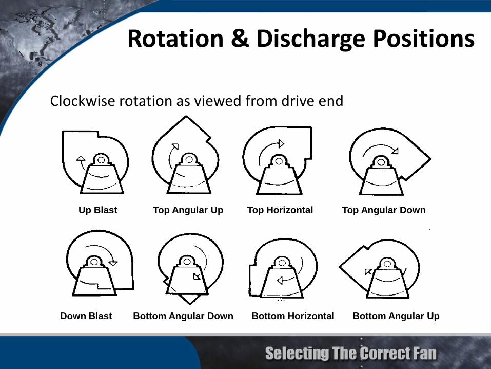
Up Blast Top Angular Up Top Horizontal Top Angular Down
Down Blast Bottom Angular Down Bottom Horizontal Bottom Angular Up
Rotation & Discharge Positions
Clockwise rotation as viewed from drive end

38
Up Blast Top Angular Up Top Horizontal Top Angular Down
Down Blast Bottom Angular Down Bottom Horizontal Bottom Angular Up
Counter-clockwise rotation viewed from drive end
Rotation & Discharge Positions

39
• AMCA designates minimum performance requirements for certain types of fans to determine fan class
1) Backward Inclined, SWSI and DWDI2) Backward Inclined airfoil, SWSI and DWDI3) Forward Curved, SWSI and DWDI4) Inline Centrifugal
• Construction standards are set based on pressure and outlet velocity (not volume and wheel size)
• Fan manufacturers use a variety of construction nomenclature (level, duty, numerical, etc.)
• In addition to performance limitations, fans have structural limitations
Fan Class of Construction

40
Centrifugal Fan Minimum Performance Points

41
Special construction used for applications where a spark may ignite explosion
– flammable or explosive gas or dust in airstream
AMCA Standard 99-0401 has guidelines for spark resistant construction with three levels
• Type A• Type B• Type C
Spark Resistant Construction

42
• Type A
– All parts of the fan in contact with the air or gas being handled shall be made of nonferrous material
• Type B
– The fan shall have a nonferrous impeller and nonferrous ring about the opening though which the shaft passes
• Type C
– The fan shall be so constructed that a shift of the impeller or shaft will not permit two ferrous parts of the fan to rub or strike
Spark Resistant Construction
43
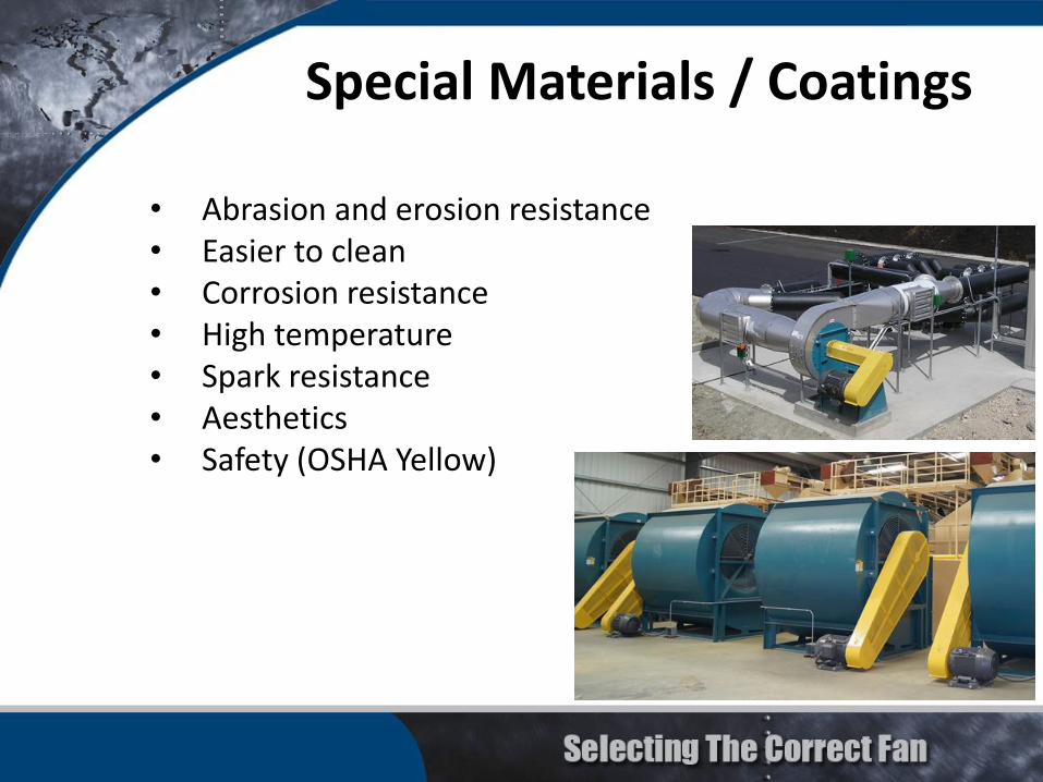
• Abrasion and erosion resistance• Easier to clean• Corrosion resistance• High temperature• Spark resistance• Aesthetics• Safety (OSHA Yellow)
Special Materials / Coatings

44
Coating Selection

45
• Power (HP, kW)
• Service Factor (Typically 15% or 1.15 SF)– Reverts to 1.0 when used with a frequency drive
• Physical Size in T-Frame or U-Frame (Automotive)
• Rotational Speed (RPM - Revolutions Per Minute)
Motor Characteristics
Typical Motor Speeds (RPM)60 Hz Power 50 Hz Power
# of Poles Synchronous Under Load # of Poles Synchronous Under Load
2 3600 3500 2 3000 2900
4 1800 1770 4 1500 1450
6 1200 1170 6 1000 970
8 900 870 8 750 720

46
Enclosure:Open Drip Proof (ODP)Totally Enclosed (TEFC, TEAO, TENV)Severe Duty (Mill & Chem., Hostile Duty, Dirty Duty...)Explosion Proof• Division I = Explosive agent present under normal
operating conditions• Division II = Explosive agent only present under
abnormal operating conditions• Class – Defines types of hazardous materials
(gases/dusts/fibers)• Group – Defines the relative degree of hazard for each
type of hazardous material
Motor Characteristics

47
– EPAct (Energy Policy Act of 1992)
• Standard efficiency (1HP and above)
– EISA (Energy Independence and Securities Act of 2007)
• Effective December 19, 2010
• EPAct efficiency eliminated (1HP and above)
• Motors manufactured for use in the US must meet the minimum efficiencies listed in NEMA MG 1, Table 12-12
Motor Efficiency

48
Advantages
• More compact
• Less maintenance
• No drive loss
• Easier to balance to low vibration levels
Disadvantages
• More difficult to make fan selections
• May require modified wheel
• Couplings can be difficult to align on Arrangement 7 or 8 fans
Direct Driven

49
Advantages
• Easy to change fan speeds and performance
• Easy to make fan selection
Disadvantages
• Requires more maintenance
• More difficult to guard
• Belts create dust (clean room problem)
• Tougher to achieve tight balance
• Drive losses due to belt slippage
V-Belt Drives

50
• Higher belt speeds tend to have higher losses than lower belt speeds at the same horsepower
• Drive losses are based on the conventional v-belt which has been the “work horse” of the drive industry for several decades
• Typically, an additional 5% to 7% should be added to fan BHP for sizing motors
Estimated Belt Drive Loss

51
Not recommend for use on fans by most fan manufacturers
• Noise (up to 13 dBA louder than V-Belt drives)
• Alignment is critical
• No slip characteristic is hard on motors
• Increased vibration
• Cost (2-3 times more expensive than V-Belt drives)
Timing Belt Drives

52
Adjustable sheaves not recommended for drives over 10 HP• Cost – Adjustable sheaves are 2-3 times more expensive than
fixed sheaves.• Adjustable sheaves use set screws to lock in pitch diameters
and set screws can vibrate loose.• Belt life is shorter on adjustable pitch drives (belt rides higher
or lower in sheave).
Dual groove drives not recommended with fractional HP motors• Motor may not be able to start fan because of the additional
resistance from the extra belts.
Belt Drive – Final Comments
53
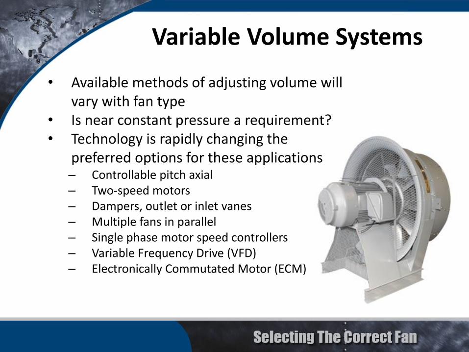
• Available methods of adjusting volume will vary with fan type
• Is near constant pressure a requirement?• Technology is rapidly changing the
preferred options for these applications– Controllable pitch axial– Two-speed motors– Dampers, outlet or inlet vanes– Multiple fans in parallel– Single phase motor speed controllers– Variable Frequency Drive (VFD)– Electronically Commutated Motor (ECM)
Variable Volume Systems
54
• Selecting the correct fan involves considering and prioritizing variables
– Application
– Performance (flow and pressure)
– First Cost of Fan
– Operating Costs
– Life, Durability & Reliability
– Space Requirements
– Simplicity of Installation
– High Temperatures and Severe Environments
– Variable Volume Requirements
– Sound Output
– Etc...
Selecting the Correct Fan
