selecting the right filter for your appplication
TRANSCRIPT

8/3/2019 Selecting the Right Filter for Your Appplication
http://slidepdf.com/reader/full/selecting-the-right-filter-for-your-appplication 1/10
/25/11 Selecting the Right Filter for Your Appplication
ww.conformit.com/artman/publish/printer_200.shtml
From
EMC COMPONENTSSelecing he Righ Filer for Yor Appplicaionb Eur Ing Keith Armstrong, CEng MIEE MIEEE
Jun 1, 2007
See this article i n our Digital Editi on
Download a pdf of this article (righ t click to save the pdf)
Filter choice can seem like a black art (although it is not) but it is fair to say that, in many applications, even
when all the best efforts have been made along the lines described below, it may be necessary to try out a
number of filters to find the correct one.
So, why bother with trying to choose them correctly in the first place? Following the guidelines presented herewill at least allow the correct size and style of filter to be chosen, so that the trial process is merely a matter of
substituting one filter for another; measuring the conducted and/or radiated emissions to see which filter gives
the best cost/performance ratio.
Where inadequate attempts are made to choose filters during the design process, Murphy’s Law (from which all
the laws of engineering and finance appear to be derived) says that the filter that turns out to be necessary will
be completely incompatible with the rest of the product. It will either be too large or too heavy to fit in the
molded plastic case and require expensive re-tooling, or it will require a fixing method that cannot be provided,
or it will have leakage currents that present safety hazards for the market segment the product is intended for. If
the correct types and styles of filters have not been already designed-in, Murphy’s Law ensures that finding the
correct filter will add to development and manufacturing costs and delay the launch of the product. So the
guidance in this article could be regarded as “anti-Murphy” precautions.
Calclaing File Specificaion
To estimate a filter’s attenuation versus frequency performance for the control of emissions, compare the
anticipated spectrum of emissions from the (unfiltered) product with the limits of the relevant EMC emissions
standard.
For immunity, estimate a filter’s performance by comparing the external electrical noise (usually taken from the
relevant EMC immunity standard) with the susceptibility of the circuits in the product and the desired level of
performance during interference incidents. Commercial/industrial immunity standards are based on economic
compromises, so to ensure sufficient reliability in real life operation (to keep warranty costs down and
customers happy) it is best to assess the electromagnetic environment(s) that the product can be subjected to
[1] and compare them with the normal immunity standards.
Where the actual emissions or susceptibility of a product is accurately known, accurate calculations can
replace crude estimations. Unfortunately, it is impossible to rely on manufacturers’ specifications when
choosing which filter to purchase, unless working in a controlled 50Ω signal environment.
Poblem Wih Impedance
Filters all work on the principle of providing a large discontinuity in the characteristic impedance seen by a radio
frequency (RF) wave travelling along a conductor, with the intention of reflecting most of the energy in the waves
associated with the unwanted noises back to where it came from.
Most filters have their performance specified by tests done with 50 source and load impedances, which leads

8/3/2019 Selecting the Right Filter for Your Appplication
http://slidepdf.com/reader/full/selecting-the-right-filter-for-your-appplication 2/10
/25/11 Selecting the Right Filter for Your Appplication
ww.conformit.com/artman/publish/printer_200.shtml
us straight to a very important point – filter specifications are often hopelessly optimistic when compared with
their performance in real life.
Consider a typical mains filter. It fits between the AC mains supply and the AC-DC converter, which is the DC
power supply for the electronic product. The impedance of the AC supply varies from 2 to 2,000 during the
day, depending on the loads that are connected to it and the measured frequency. The RF characteristic
impedance of the mains lead to the product is around 150, and the impedance of the AC-DC converter
circuitry looks like a short-circuit when the rectifiers are turned on and an open-circuit at all other times.
Filter specifications employ 50 source and load impedances because most RF test equipment uses 50sources, loads and cables; and never mind the fact that for many practical uses of filters the attenuation
measurements obtained by this method are at best optimistic and at worst misleading.
Because filters are made from inductors and capacitors, they are resonant circuits and their performance and
resonance can depend critically on their source and load impedances. In real life it is sometimes possible for
an expensive filter with an excellent 50/50 performance specification to have worse performance than a
cheaper one with a mediocre 50/50 specification.
Mains Filters
Mains filters with a single stage, such as those shown in Figure 1, are very sensitive to source and load
impedances and can easily provide gain, rather than attenuation, when operated with source and load
impedances other than their specification. This gain usually pops up in the 150kHz to 4MHz region and isusually between 10 and 20dB, leading to the possibility that fitting a single-stage mains filter can increase
emissions and/or worsen susceptibility in that frequency range.
Figure 1: Some tpical single-stage mains filters
Filters with two or more stages, such as those in Figure 2, are able to maintain an internal node at an
impedance which does not depend very much on source and load impedances, so they are better able to
provide an attenuation performance at least vaguely in line with their 50/50 specification. Of course, they are
larger and cost more.

8/3/2019 Selecting the Right Filter for Your Appplication
http://slidepdf.com/reader/full/selecting-the-right-filter-for-your-appplication 3/10
/25/11 Selecting the Right Filter for Your Appplication
ww.conformit.com/artman/publish/printer_200.shtml
Figure 2: A tpical 2-stage mains filter
To deal with this impedance problem, it is best to only purchase filters for which the manufacturer has specified
both common-mode (CM, “asymmetrical”) and differential-mode (DM, “symmetrical”) performance, with both
“matched” 50/50 and “mismatched” sources and loads. Mismatched measurements are made using a 0.1
source and 100 load (and vice-versa).
The trick is to draw an attenuation versus frequency curve which follows the worst-case figures from all of the
six attenuation curves provided, and to assume that this “overall worst-case” curve represents the filter’s actual
performance. Figure 3 shows an example of this procedure. When filters are chosen in this way, to suit the
predicted needs of their application, their performance is usually as good or better than expected.

8/3/2019 Selecting the Right Filter for Your Appplication
http://slidepdf.com/reader/full/selecting-the-right-filter-for-your-appplication 4/10
/25/11 Selecting the Right Filter for Your Appplication
ww.conformit.com/artman/publish/printer_200.shtml
Figure 3: Deriving a reliable filter attenuation curve from manufacturers data
M ai fie achiee aeai f CM iga b ig CM che, -ae Y caaci beee
hae ad gd. F aeai f diffeeia-de iga he e X caaci ceced beee
hae, he eaage idcace f he CM che.
B fie hich hae ce ih high ee f -feec ie f ich-de cee, hae agee ce, die ad he ie, fe eed e diffeeia-de aeai ha ca be achieed
b he abe ea, ad a eed e diffeeia-de che a h i Fige 4. Mageic aai
f he che ce ae i diffic ge a gea dea f diffeeia-de idcace i a a acage,
hee fie ed be age ad e eeie.

8/3/2019 Selecting the Right Filter for Your Appplication
http://slidepdf.com/reader/full/selecting-the-right-filter-for-your-appplication 5/10
/25/11 Selecting the Right Filter for Your Appplication
ww.conformit.com/artman/publish/printer_200.shtml
Fige 4: Eample of main file fo a ich-mode poe conee
Most mains filters use Y capacitors connected between phases and ground, with values around a few nF, so as
not to exceed the ground leakage limits imposed by the relevant safety standard. The general rule is that the Y
capacitors should be connected to the side of the filter that has the highest levels of noise on them. For
example, (typically) the Y capacitors would be fitted to a filters mains input when filtering a linear power supply
for an entirely low-frequency analogue product, but would be fitted to the filters mains output when filtering a
switch-mode converter and/or a product that contains any digital processing or RF analogue circuits.
For medical apparatus, especially if patient-connected, the ground-leakage currents may be limited to such low
levels that the use of any reasonable size of Y capacitors is impossible. Such filters need to achieve moreattenuation from their CM chokes and/or by using more stages, and so tend to be larger and more expensive.
(Although it is much better is to make the patient-connected equipment battery-powered and connected to the
mains-powered equipment solely through an opto-coupler or fiber-optic link, so that the ground leakage current
caused by Y capacitors in the mains power supply cannot compromise the safety of the patient.)
In large systems, the ground leakages from the small Y capacitors in a number of items of equipment can add
up to create very large ground leakage currents (70 amps of leakage current has been seen in the main earth
terminal of a building where 10,000 PCs and their monitors were in use). These can cause ground voltage
differences that impose hum and high levels of transients on cables between different equipment. Modern best-
practices call for three-dimensionally meshed ground system bonding (see IEC 61000-5-2 [2] and [3]) but many
older installations do not employ this technique, so apparatus intended for use in large systems can benefit
from the use of filters with small or even non-existent Y capacitors, even though such filters are larger and morecostly.
It is always best to use mains filters for which safety approval certificates have been obtained from their
manufacturer. These should be checked for authenticity (ask their issuing safety agency) and also checked for
temperature range, voltage and current ratings, and the application of the appropriate safety standard(s) for the
application.
Mains filters depend upon inductors, whose permeability varies with temperature and current. [4] shows that
varying the mains voltage, load current and ambient temperature within the rated ranges reduced the
attenuation of an example mains filter by up to 20dB, compared with the performance it achieved during normal
commercial/industrial emissions testing. So, to ensure acceptable emissions and immunity performance in real

8/3/2019 Selecting the Right Filter for Your Appplication
http://slidepdf.com/reader/full/selecting-the-right-filter-for-your-appplication 6/10
/25/11 Selecting the Right Filter for Your Appplication
ww.conformit.com/artman/publish/printer_200.shtml
life (and help keep customers happy) it is best to select a mains filter that achieves significantly more
attenuation than is required merely to pass the usual EMC tests.
Signal Filters
It is no good trying to reduce conducted or radiated emissions with differential-mode filters if the emissions are
caused by the spectrum of the wanted signal. But CM filtering may be applied to frequencies within the wanted
signal’s spectrum, since the wanted signals are always differential and so are unaffected by CM filtering. CM
filtering is a powerful technique, because CM currents cause most of the emissions between 1 and 1000MHz.
Operation of a digital IC’s internal circuits create ground-bounce noise, and even if the RF bonding between theprinted-circuit board’s (PCB’s) 0V plane and the chassis are perfect this can still add a great deal of
unexpected high-frequency noise to all of a device’s inputs and outputs. This extra noise can affect the
selection of signal filters.
Filters for low level digital or analogue signals may need to use two (or more) stage filters to achieve sufficient
immunity, especially where very sensitive electronics are employed. But high level digital or analogue signals
are often not very sensitive and simple single-stage R, L, C, RC, LC, Tee, or filters are usually sufficient, as
shown in Figure 5.
Figure 5: Different tpes of single-line filters
R and L filters work by creating a high impedance to reflect the interference, but can usually only achieve a few
dB of attenuation. They are best used where the source and load impedances are low. L filters suffer fromresonances and so are best made from soft ferrites (see below). L and R filter components have their
attenuation compromised at high frequencies by the stray capacitance that exists between their terminals (and
between their PCB pads and traces, if they are PCB-mounted).
C filters rely on creating a low impedance to reflect the interference, and are best used where the source and
load impedances are high. Performance figures published for C filters are often very good – much better than
they usually achieve in real life – due to the stray inductance in their leads and ground terminations.
RC filters, and resistive Tee or filters that use high R values are the most predictable because they cannot
resonate in any very dramatic fashion, but high values of R (say, above 1kΩ) may not be able to be used where
the wanted signals are more than a few kHz or kb/s.

8/3/2019 Selecting the Right Filter for Your Appplication
http://slidepdf.com/reader/full/selecting-the-right-filter-for-your-appplication 7/10
8/3/2019 Selecting the Right Filter for Your Appplication
http://slidepdf.com/reader/full/selecting-the-right-filter-for-your-appplication 8/10
/25/11 Selecting the Right Filter for Your Appplication
ww.conformit.com/artman/publish/printer_200.shtml
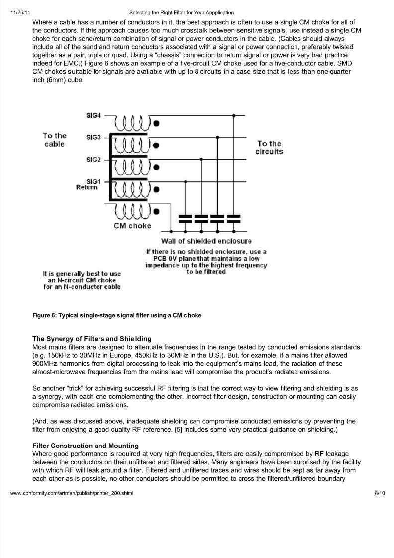
Where a cable has a number of conductors in it, the best approach is often to use a single CM choke for all of
the conductors. If this approach causes too much crosstalk between sensitive signals, use instead a single CM
choke for each send/return combination of signal or power conductors in the cable. (Cables should always
include all of the send and return conductors associated with a signal or power connection, preferably twisted
together as a pair, triple or quad. Using a “chassis” connection to return signal or power is very bad practice
indeed for EMC.) Figure 6 shows an example of a five-circuit CM choke used for a five-conductor cable. SMD
CM chokes suitable for signals are available with up to 8 circuits in a case size that is less than one-quarter
inch (6mm) cube.
Figure 6: Tpical single-stage signal filter using a CM choke
The Snerg of Filters and Shielding
Most mains filters are designed to attenuate frequencies in the range tested by conducted emissions standards
(e.g. 150kHz to 30MHz in Europe, 450kHz to 30MHz in the U.S.). But, for example, if a mains filter allowed
900MHz harmonics from digital processing to leak into the equipments mains lead, the radiation of these
almost-microwave frequencies from the mains lead will compromise the products radiated emissions.
So another “trick” for achieving successful RF filtering is that the correct way to view filtering and shielding is asa synergy, with each one complementing the other. Incorrect filter design, construction or mounting can easily
compromise radiated emissions.
(And, as was discussed above, inadequate shielding can compromise conducted emissions by preventing the
filter from enjoying a good quality RF reference. [5] includes some very practical guidance on shielding.)
Filter Construction and Mounting
Where good performance is required at very high frequencies, filters are easily compromised by RF leakage
between the conductors on their unfiltered and filtered sides. Many engineers have been surprised by the facility
with which RF will leak around a filter. Filtered and unfiltered traces and wires should be kept as far away from
each other as is possible, no other conductors should be permitted to cross the filtered/unfiltered boundary

8/3/2019 Selecting the Right Filter for Your Appplication
http://slidepdf.com/reader/full/selecting-the-right-filter-for-your-appplication 9/10
/25/11 Selecting the Right Filter for Your Appplication
ww.conformit.com/artman/publish/printer_200.shtml
without being adequately filtered (or adequately shielded), and it may be necessary to use shielding techniques
to control any remaining leakages.
Where an external cable to be filtered connects to an unshielded PCB, the filter should employ the PCB’s 0V
plane as its RF reference and be directly bonded to it with very low inductance. [6] includes a great deal of
detail on combining filtering with shielding on a PCB.
Where an external cable to be filtered enters a shielded enclosure, the filter should be directly bonded to the
shielding surface at the point where the cable penetrates the enclosure. It is best if the filter’s metal body bonds
to the shielding surface all around the aperture it fits in, and some filters are provided with multiple groundbonding points for this purpose, whereas others may need to use a conductive gasket. Bulkhead-mounted
filters are the best (e.g. “feedthrough” filters) but are often quite costly items.
Some types of signal cable connectors are available with built-in “feedthrough” filters, such as D-types. These
are usually just 1nF capacitors but L, Tee and types are also available.
For mains filters, the IEC 60320-style inlet is the most common commercial style of bulkhead filter. An IEC
60320 inlet filter with a metal body installed in a shielded enclosure can only achieve good attenuation at
frequencies above 30MHz if its metal body has a seamless construction and if its body makes a very low
inductance connection directly to the shielding surface as shown in Figure 7.
Figure 7: Bonding filters to the all of a shielded enclosure
For high powers, most commercial and industrial mains filters use spade or screw-terminal connections,
making bulkhead mounting impossible.
Figure 7 shows a screw-terminal filter mounted using the “dirty-box” method, which encloses it in an additional
shielded enclosure within the main shielded enclosure. Even though the input and output cables in the “dirty
box” are kept very short and far away from each other, high frequencies may still leak between them and ferrite
cylinders or high-frequency feedthrough filters may be needed at the point where one of the cables penetrates
the wall of the “dirty box”.
8/3/2019 Selecting the Right Filter for Your Appplication
http://slidepdf.com/reader/full/selecting-the-right-filter-for-your-appplication 10/10
/25/11 Selecting the Right Filter for Your Appplication
ww conformit com/artman/publish/printer 200 shtml
Some filter manufacturers offer room filters intended for use with shielded rooms in EMC test facilities. These
typically use screw-terminal connections and provide their own dirty box designed to prevent undue RF
leakage between their inputs and filtered outputs.
Keith Armstrong is a principal with Cherry Clough Consultants ( www.cherryclough.com ). He can be reached at
Editors Note: Earlier versions of this article appeared in the EMC Compliance Journal, August 1998
( www.compliance-club.com ), and the June 2006 issue of Conformity.
Refeence
. Assessing an EM Environment , Keith Armstrong, from the Publications & Downloads page at
www.cherryclough.com.
. IEC 61000-5-2:1997, Electromagnetic Compatibility (EMC) Part 5: Installation and Mitigation
Guidelines - Section 2: Earthing and cabling .
. EMC for Systems and Installations, Keith Armstrong, a series of six articles in the EMC Compliance
Journal in 2000, via the Publications & Downloads page at www.cherryclough.com.
. EMC Performance of Drive Application Under Real Load Condition, F. Beck, J. Sroka, Schaffner EMV
AG application note, 11 March 1999.
.
Design Techniques for EMC , Keith Armstrong, a series of six articles in the EMC Compliance Journal in1999, via the Publications & Downloads page at www.cherryclough.com. These articles are being
rewritten and republished during 2006-7, the new ones appearing first at www.compliance-club.com.
. Advanced PCB Design and Layout for EMC , Keith Armstrong, a series of eight articles in the EMC
Compliance Journal 2004-5, via the Publications & Downloads page at www.cherryclough.com.
© Copyright 2007 Conformity