selective coordination - cooper industries coordination with fuses to determine fuse selectivity is...
TRANSCRIPT
1©2008 Cooper Bussmann
Selective Coordination
What Is Selective Coordination?Today, more than ever, one of the most important parts of any facility is theelectrical distribution system. Nothing will stop all activity, paralyze production, inconvenience and disconcert people, and possibly cause apanic, more than a major power failure. Selective coordination is critical forthe reliability of the electrical distribution system and must be analyzed.Selective coordination of overcurrent protective devices is required by theNEC® for a few building systems for a limited number of circuits that supplypower to vital loads. These requirements will be discussed in a later section.
For circuits supplying power to all other loads, selective coordination is avery desirable design consideration, but not mandatory. It is important todeal with selective coordination in the design phase. After switchboards,distribution panels, motor control centers, lighting panelboards, etc. areinstalled, there typically is little that can be done to retroactively "fix" a system that is not selectively coordinated.
While it's very important, it is not enough to select protective devices basedsolely on their ability to carry the system load current and interrupt the maximum fault current at their respective points of application. It is important to note that the type of overcurrent protective devices and ratings(or settings) selected determine if a system is selectively coordinated. A properly engineered and installed system will allow only the nearestupstream overcurrent protective device to open for both overloads and alltypes of short-circuits, leaving the remainder of the system undisturbed andpreserving continuity of service. Isolation of a faulted circuit from theremainder of the installation is critical in today’s modern electrical systems.Power blackouts cannot be tolerated.
Article 100 of the NEC® defines this as:
Coordination (Selective). Localization of an overcurrent condition to restrictoutages to the circuit or equipment affected, accomplished by the choiceof overcurrent protective devices and their ratings or settings.
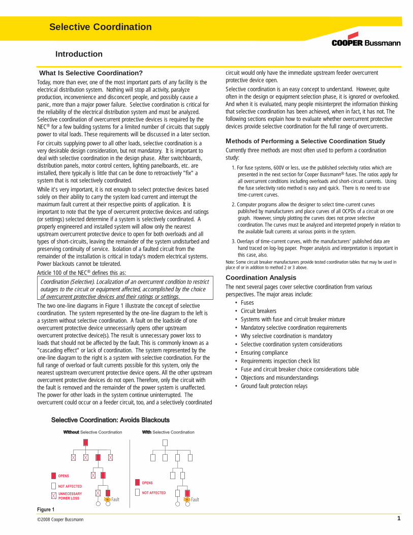
The two one-line diagrams in Figure 1 illustrate the concept of selectivecoordination. The system represented by the one-line diagram to the left isa system without selective coordination. A fault on the loadside of one overcurrent protective device unnecessarily opens other upstream overcurrent protective device(s). The result is unnecessary power loss toloads that should not be affected by the fault. This is commonly known as a"cascading effect" or lack of coordination. The system represented by theone-line diagram to the right is a system with selective coordination. For thefull range of overload or fault currents possible for this system, only thenearest upstream overcurrent protective device opens. All the other upstreamovercurrent protective devices do not open. Therefore, only the circuit withthe fault is removed and the remainder of the power system is unaffected.The power for other loads in the system continue uninterrupted. The overcurrent could occur on a feeder circuit, too, and a selectively coordinated
circuit would only have the immediate upstream feeder overcurrent protective device open.
Selective coordination is an easy concept to understand. However, quiteoften in the design or equipment selection phase, it is ignored or overlooked.And when it is evaluated, many people misinterpret the information thinkingthat selective coordination has been achieved, when in fact, it has not. Thefollowing sections explain how to evaluate whether overcurrent protectivedevices provide selective coordination for the full range of overcurrents.
Methods of Performing a Selective Coordination StudyCurrently three methods are most often used to perform a coordinationstudy:
1. For fuse systems, 600V or less, use the published selectivity ratios which are presented in the next section for Cooper Bussmann® fuses. The ratios apply forall overcurrent conditions including overloads and short-circuit currents. Usingthe fuse selectivity ratio method is easy and quick. There is no need to usetime-current curves.
2. Computer programs allow the designer to select time-current curves published by manufacturers and place curves of all OCPDs of a circuit on onegraph. However, simply plotting the curves does not prove selective coordination. The curves must be analyzed and interpreted properly in relation tothe available fault currents at various points in the system.
3. Overlays of time-current curves, with the manufacturers’ published data arehand traced on log-log paper. Proper analysis and interpretation is important inthis case, also.
Note: Some circuit breaker manufacturers provide tested coordination tables that may be used inplace of or in addition to method 2 or 3 above.
Coordination AnalysisThe next several pages cover selective coordination from various perspectives. The major areas include:
• Fuses• Circuit breakers• Systems with fuse and circuit breaker mixture• Mandatory selective coordination requirements• Why selective coordination is mandatory• Selective coordination system considerations• Ensuring compliance• Requirements inspection check list• Fuse and circuit breaker choice considerations table• Objections and misunderstandings• Ground fault protection relays
Introduction
WithoutWithout Selective Coordination WithWith Selective Coordination
Selective Coordination: Avoids BlackoutsSelective Coordination: Avoids BlackoutsSelective Coordination: Avoids BlackoutsSelective Coordination: Avoids Blackouts
OPENS
NOT AFFECTED
UNNECESSARY
POWER LOSS
OPENS
NOT AFFECTED
Fault Fault
Selective Coordination
Figure 1
2 ©2008 Cooper Bussmann
Selective Coordination
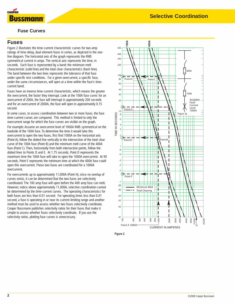
FusesFigure 2 illustrates the time-current characteristic curves for two amp ratings of time-delay, dual-element fuses in series, as depicted in the one-line diagram. The horizontal axis of the graph represents the RMS symmetrical current in amps. The vertical axis represents the time, in seconds. Each fuse is represented by a band: the minimum melt characteristic (solid line) and the total clear characteristics (hash line).The band between the two lines represents the tolerance of that fuse under specific test conditions. For a given overcurrent, a specific fuse,under the same circumstances, will open at a time within the fuse’s time-current band.
Fuses have an inverse time-current characteristic, which means the greaterthe overcurrent, the faster they interrupt. Look at the 100A fuse curve: for anovercurrent of 200A, the fuse will interrupt in approximately 200 secondsand for an overcurrent of 2000A, the fuse will open in approximately 0.15second.
In some cases, to assess coordination between two or more fuses, the fusetime-current curves are compared. This method is limited to only the overcurrent range for which the fuse curves are visible on the graph.
For example: Assume an overcurrent level of 1000A RMS symmetrical on theloadside of the 100A fuse. To determine the time it would take this overcurrent to open the two fuses, first find 1000A on the horizontal axis(Point A), follow the dotted line vertically to the intersection of the total clearcurve of the 100A fuse (Point B) and the minimum melt curve of the 400Afuse (Point C). Then, horizontally from both intersection points, follow the dotted lines to Points D and E. At 1.75 seconds, Point D represents the maximum time the 100A fuse will take to open the 1000A overcurrent. At 90seconds, Point E represents the minimum time at which the 400A fuse couldopen this overcurrent. These two fuses are coordinated for a 1000A overcurrent.
For overcurrents up to approximately 11,000A (Point H), since no overlap ofcurves exists, it can be determined that the two fuses are selectively coordinated. The 100 amp fuse will open before the 400 amp fuse can melt.However, notice above approximately 11,000A, selective coordination cannotbe determined by the time-current curves. The operating characteristics forboth fuses are less than 0.01 second. For operating times less than 0.01second, a fuse is operating in or near its current-limiting range and anothermethod must be used to assess whether two fuses selectively coordinate.Cooper Bussmann publishes selectivity ratios for their fuses that make itsimple to assess whether fuses selectively coordinate. If you use the selectivity ratios, plotting fuse curves is unnecessary.
Fuse Curves
Point BPoint D
Point F
Point A 1000A
600
400
300
200
100
80
60
40
30
20
108
6
4
3
2
1.8
.6
.4
.3
.2
.1.08
.04
.06
.03
.02
.01
CURRENT IN AMPERES
TIM
E IN
SE
CO
ND
S
100A
400A
Minimum MeltTotal Clearing
Point G
Available FaultCurrentLevel1000A
400A
100A
Figure 3a.
Point CPoint E
100
200
300
400
600
800
1000
2000
3000
4000
6000
8000
10,0
00
20,0
00
H
Figure 2
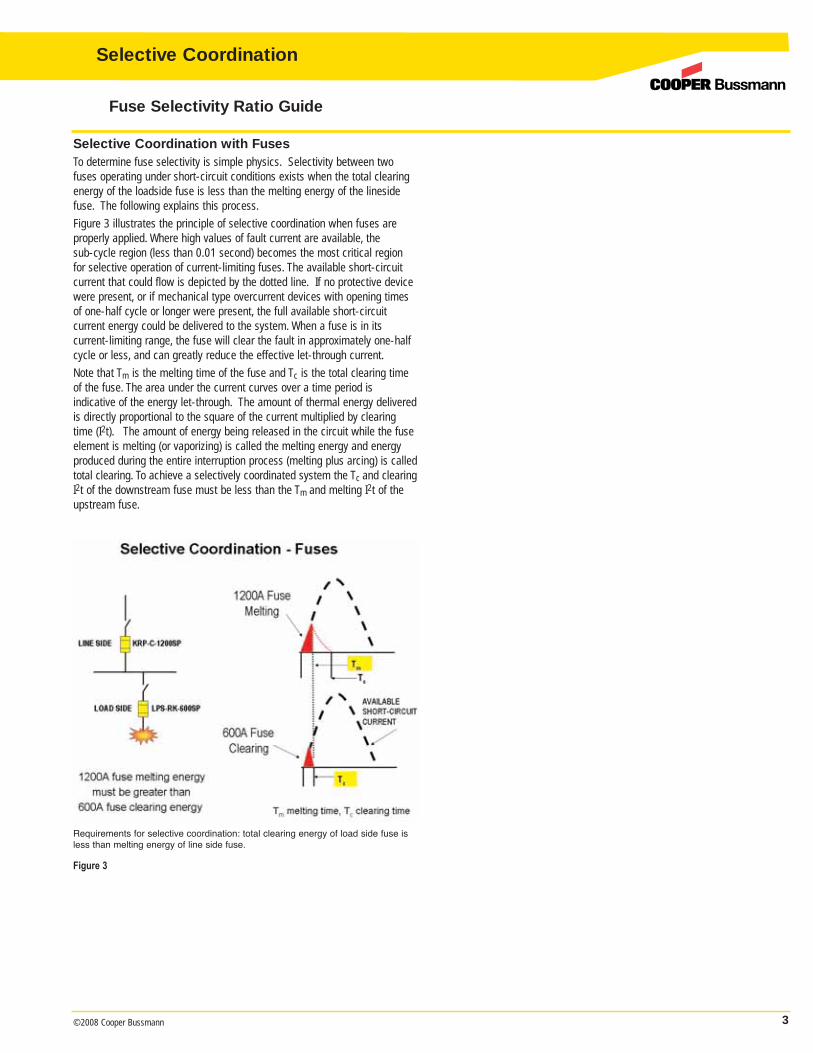
Selective Coordination with FusesTo determine fuse selectivity is simple physics. Selectivity between twofuses operating under short-circuit conditions exists when the total clearingenergy of the loadside fuse is less than the melting energy of the linesidefuse. The following explains this process.
Figure 3 illustrates the principle of selective coordination when fuses areproperly applied. Where high values of fault current are available, the sub-cycle region (less than 0.01 second) becomes the most critical regionfor selective operation of current-limiting fuses. The available short-circuitcurrent that could flow is depicted by the dotted line. If no protective devicewere present, or if mechanical type overcurrent devices with opening timesof one-half cycle or longer were present, the full available short-circuit current energy could be delivered to the system. When a fuse is in itscurrent-limiting range, the fuse will clear the fault in approximately one-halfcycle or less, and can greatly reduce the effective let-through current.
Note that Tm is the melting time of the fuse and Tc is the total clearing timeof the fuse. The area under the current curves over a time period is indicative of the energy let-through. The amount of thermal energy deliveredis directly proportional to the square of the current multiplied by clearingtime (I2t). The amount of energy being released in the circuit while the fuseelement is melting (or vaporizing) is called the melting energy and energy produced during the entire interruption process (melting plus arcing) is calledtotal clearing. To achieve a selectively coordinated system the Tc and clearingI2t of the downstream fuse must be less than the Tm and melting I2t of theupstream fuse.
3©2008 Cooper Bussmann
Selective Coordination
Fuse Selectivity Ratio Guide
Figure 3
Requirements for selective coordination: total clearing energy of load side fuse isless than melting energy of line side fuse.
4 ©2008 Cooper Bussmann
Selective Coordination
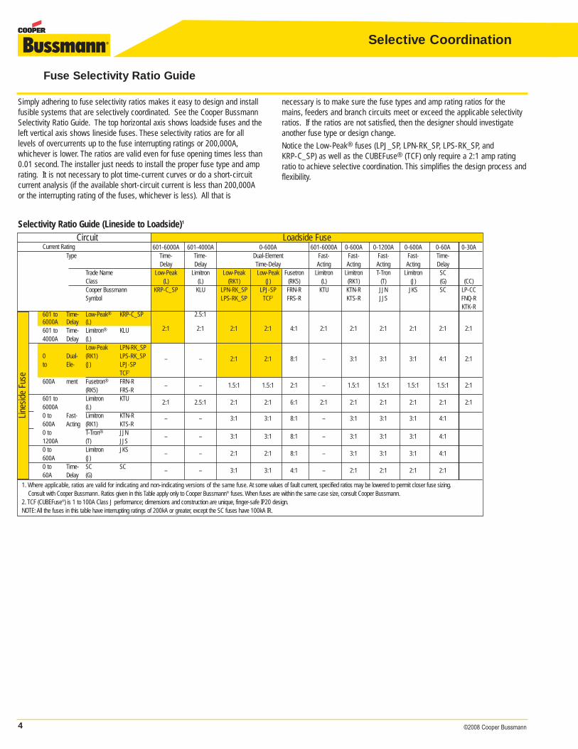
Simply adhering to fuse selectivity ratios makes it easy to design and installfusible systems that are selectively coordinated. See the Cooper BussmannSelectivity Ratio Guide. The top horizontal axis shows loadside fuses and theleft vertical axis shows lineside fuses. These selectivity ratios are for all levels of overcurrents up to the fuse interrupting ratings or 200,000A,whichever is lower. The ratios are valid even for fuse opening times less than0.01 second. The installer just needs to install the proper fuse type and amprating. It is not necessary to plot time-current curves or do a short-circuitcurrent analysis (if the available short-circuit current is less than 200,000Aor the interrupting rating of the fuses, whichever is less). All that is
necessary is to make sure the fuse types and amp rating ratios for themains, feeders and branch circuits meet or exceed the applicable selectivityratios. If the ratios are not satisfied, then the designer should investigateanother fuse type or design change.
Notice the Low-Peak® fuses (LPJ_SP, LPN-RK_SP, LPS-RK_SP, and KRP-C_SP) as well as the CUBEFuse® (TCF) only require a 2:1 amp ratingratio to achieve selective coordination. This simplifies the design process andflexibility.
Fuse Selectivity Ratio Guide
Circuit Loadside FuseCurrent Rating 601-6000A 601-4000A 0-600A 601-6000A 0-600A 0-1200A 0-600A 0-60A 0-30A
Type Time- Time- Dual-Element Fast- Fast- Fast- Fast- Time-Delay Delay Time-Delay Acting Acting Acting Acting Delay
Trade Name Low-Peak Limitron Low-Peak Low-Peak Fusetron Limitron Limitron T-Tron Limitron SCClass (L) (L) (RK1) (J) (RK5) (L) (RK1) (T) (J) (G) (CC)Cooper Bussmann KRP-C_SP KLU LPN-RK_SP LPJ-SP FRN-R KTU KTN-R JJN JKS SC LP-CCSymbol LPS-RK_SP TCF2 FRS-R KTS-R JJS FNQ-R
KTK-R601 to Time- Low-Peak® KRP-C_SP 2.5:16000A Delay (L)601 to Time- Limitron® KLU 2:1 2:1 2:1 2:1 4:1 2:1 2:1 2:1 2:1 2:1 2:1
4000A Delay (L)Low-Peak LPN-RK_SP
0 Dual- (RK1) LPS-RK_SP 2:1to Ele- (J) LPJ-SP
– – 2:1 2:1 8:1 – 3:1 3:1 3:1 4:1
TCF1
600A ment Fusetron® FRN-R– – 1.5:1 1.5:1 2:1 – 1.5:1 1.5:1 1.5:1 1.5:1 2:1
(RK5) FRS-R601 to Limitron KTU
2:1 2.5:1 2:1 2:1 6:1 2:1 2:1 2:1 2:1 2:1 2:16000A (L)0 to Fast- Limitron KTN-R – – 3:1 3:1 8:1 – 3:1 3:1 3:1 4:1600A Acting (RK1) KTS-R0 to T-Tron® JJN
– – 3:1 3:1 8:1 – 3:1 3:1 3:1 4:11200A (T) JJS0 to Limitron JKS
– – 2:1 2:1 8:1 – 3:1 3:1 3:1 4:1600A (J)0 to Time- SC SC
– – 3:1 3:1 4:1 – 2:1 2:1 2:1 2:160A Delay (G)
1. Where applicable, ratios are valid for indicating and non-indicating versions of the same fuse. At some values of fault current, specified ratios may be lowered to permit closer fuse sizing.Consult with Cooper Bussmann. Ratios given in this Table apply only to Cooper Bussmann® fuses. When fuses are within the same case size, consult Cooper Bussmann.
2. TCF (CUBEFuse®) is 1 to 100A Class J performance; dimensions and construction are unique, finger-safe IP20 design.NOTE: All the fuses in this table have interrupting ratings of 200kA or greater, except the SC fuses have 100kA IR.
Line
side
Fus
e
Selectivity Ratio Guide (Lineside to Loadside)1
5©2008 Cooper Bussmann
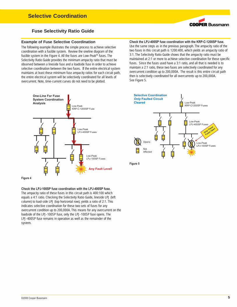
Example of Fuse Selective CoordinationThe following example illustrates the simple process to achieve selectivecoordination with a fusible system. Review the oneline diagram of thefusible system in the Figure 4. All the fuses are Low-Peak® fuses. TheSelectivity Ratio Guide provides the minimum ampacity ratio that must beobserved between a lineside fuse and a loadside fuse in order to achieveselective coordination between the two fuses. If the entire electrical systemmaintains at least these minimum fuse ampacity ratios for each circuit path,the entire electrical system will be selectively coordinated for all levels ofovercurrent. Note, time-current curves do not need to be plotted.
Check the LPJ-400SP fuse coordination with the KRP-C-1200SP fuse.Use the same steps as in the previous paragraph. The ampacity ratio of thetwo fuses in this circuit path is 1200:400, which yields an ampacity ratio of3:1. The Selectivity Ratio Guide shows that the ampacity ratio must be maintained at 2:1 or more to achieve selective coordination for these specificfuses. Since the fuses used have a 3:1 ratio, and all that is needed is tomaintain a 2:1 ratio, these two fuses are selectively coordinated for anyovercurrent condition up to 200,000A. The result is this entire circuit paththen is selectively coordinated for all overcurrents up to 200,000A.See Figure 5.
Check the LPJ-100SP fuse coordination with the LPJ-400SP fuse.The ampacity ratio of these fuses in this circuit path is 400:100 whichequals a 4:1 ratio. Checking the Selectivity Ratio Guide, lineside LPJ (left column) to load-side LPJ (top horizontal row), yields a ratio of 2:1. This indicates selective coordination for these two sets of fuses for any overcurrent condition up to 200,000A. This means for any overcurrent on theloadside of the LPJ-100SP fuse, only the LPJ-100SP fuse opens. The LPJ-400SP fuse remains in operation as well as the remainder of the system.
One-Line For FuseSystem CoordinationAnalysis
Low-PeakKRP-C-1200SP Fuse
Low-PeakLPJ-400SP Fuses
Low-PeakLPJ-100SP Fuses
Any Fault Level!
Any Fault Level !
Selective CoordinationOnly Faulted Circuit Cleared Low-Peak
KRP-C1200SP Fuses
Low-PeakLPJ-400SP Fuses
Low-PeakLPJ-100SP Fuses
Only These
Fuses Open
Opens
NotAffected
Figure 4
Figure 5
Fuse Selectivity Ratio Guide
Selective Coordination
6 ©2008 Cooper Bussmann
Selective Coordination
Fusible Lighting Panels
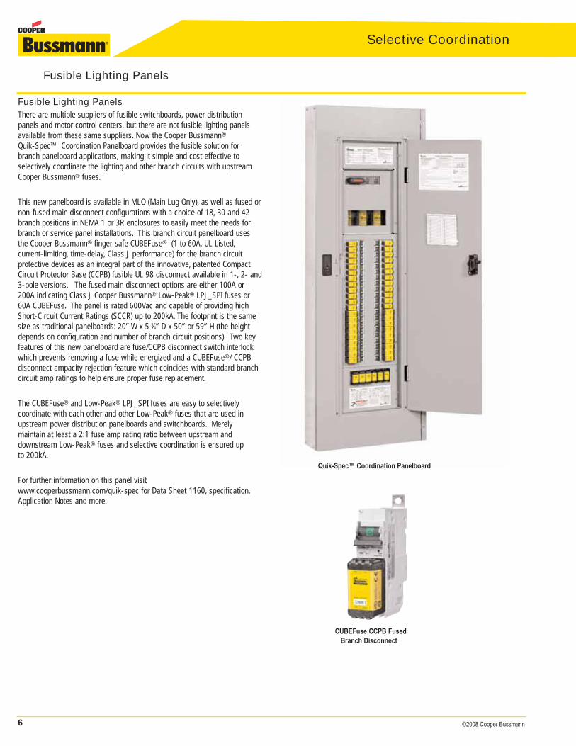
Fusible Lighting PanelsThere are multiple suppliers of fusible switchboards, power distribution panels and motor control centers, but there are not fusible lighting panelsavailable from these same suppliers. Now the Cooper Bussmann®
Quik-Spec™ Coordination Panelboard provides the fusible solution forbranch panelboard applications, making it simple and cost effective to selectively coordinate the lighting and other branch circuits with upstreamCooper Bussmann® fuses.
This new panelboard is available in MLO (Main Lug Only), as well as fused ornon-fused main disconnect configurations with a choice of 18, 30 and 42branch positions in NEMA 1 or 3R enclosures to easily meet the needs forbranch or service panel installations. This branch circuit panelboard usesthe Cooper Bussmann® finger-safe CUBEFuse® (1 to 60A, UL Listed,current-limiting, time-delay, Class J performance) for the branch circuit protective devices as an integral part of the innovative, patented CompactCircuit Protector Base (CCPB) fusible UL 98 disconnect available in 1-, 2- and3-pole versions. The fused main disconnect options are either 100A or200A indicating Class J Cooper Bussmann® Low-Peak® LPJ_SPI fuses or60A CUBEFuse. The panel is rated 600Vac and capable of providing highShort-Circuit Current Ratings (SCCR) up to 200kA. The footprint is the samesize as traditional panelboards: 20” W x 5 3⁄4” D x 50” or 59” H (the heightdepends on configuration and number of branch circuit positions). Two keyfeatures of this new panelboard are fuse/CCPB disconnect switch interlockwhich prevents removing a fuse while energized and a CUBEFuse®/ CCPBdisconnect ampacity rejection feature which coincides with standard branchcircuit amp ratings to help ensure proper fuse replacement.
The CUBEFuse® and Low-Peak® LPJ_SPI fuses are easy to selectively coordinate with each other and other Low-Peak® fuses that are used inupstream power distribution panelboards and switchboards. Merely maintain at least a 2:1 fuse amp rating ratio between upstream and downstream Low-Peak® fuses and selective coordination is ensured up to 200kA.
For further information on this panel visit www.cooperbussmann.com/quik-spec for Data Sheet 1160, specification,Application Notes and more.
Quik-Spec™ Coordination Panelboard
CUBEFuse CCPB FusedBranch Disconnect
7©2008 Cooper Bussmann
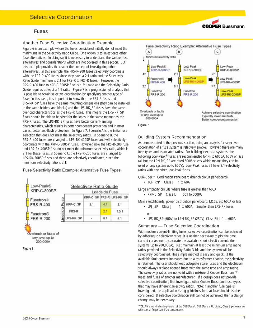
Another Fuse Selective Coordination ExampleFigure 6 is an example where the fuses considered initially do not meet theminimums in the Selectivity Ratio Guide. One option is to investigate otherfuse alternatives. In doing so, it is necessary to understand the various fusealternatives and considerations which are not covered in this section. Butthis example provides the reader the concept of investigating other alternatives. In this example, the FRS-R-200 fuses selectively coordinatewith the FRS-R-400 fuses since they have a 2:1 ratio and the SelectivityRatio Guide minimum is 2:1 for FRS-R to FRS-R fuses. However, the FRS-R-400 fuse to KRP-C-800SP fuse is a 2:1 ratio and the Selectivity RatioGuide requires at least a 4:1 ratio. Figure 7 is a progression of analysis thatis possible to obtain selective coordination by specifying another type offuse. In this case, it is important to know that the FRS-R fuses and LPS-RK_SP fuses have the same mounting dimensions (they can be installedin the same holders and blocks) and the LPS-RK_SP fuses have the sameoverload characteristics as the FRS-R fuses. This means the LPS-RK_SPfuses should be able to be sized for the loads in the same manner as theFRS-R fuses. The LPS-RK_SP fuses have better current-limiting characteristics, which results in better component protection and in mostcases, better arc-flash protection. In Figure 7, Scenario A is the initial fuseselection that does not meet the selectivity ratios. In Scenario B, the FRS-R-400 fuses are changed to LPS-RK-400SP fuses and will selectivelycoordinate with the KRP-C-800SP fuses. However, now the FRS-R-200 fuseand LPS-RK-400SP fuse do not meet the minimum selectivity ratio, which is8:1 for these fuses. In Scenario C, the FRS-R-200 fuses are changed toLPS-RK-200SP fuses and these are selectively coordinated, since the minimum selectivity ratio is 2:1.
Building System RecommendationAs demonstrated in the previous section, doing an analysis for selectivecoordination of a fuse system is relatively simple. However, there are manyfuse types and associated ratios. For building electrical systems, the following Low-Peak® fuses are recommended for 1⁄10 to 6000A, 600V or less(all but the LPN-RK_SP are rated 600V or less which means they can beused on any system up to 600V). Low-Peak fuses all have 2:1 selectivityratios with any other Low-Peak fuses.
Quik-Spec™ Cordination Panelboard (branch circuit panelboard) • TCF_RN* Class J 1 to 60A
Large ampacity circuits where fuse is greater than 600A• KRP-C_SP Class L 601 to 6000A
Main switchboards, power distribution panelboard, MCCs, etc 600A or less• LPJ_SP Class J 1 to 600A Smaller than LPS-RK fuses
or• LPS-RK_SP (600V) or LPN-RK_SP (250V) Class RK1 1 to 600A
Summary — Fuse Selective CoordinationWith modern current-limiting fuses, selective coordination can be achievedby adhering to selectivity ratios. It is neither necessary to plot the time current curves nor to calculate the available short-circuit currents (for systems up to 200,000A). Just maintain at least the minimum amp ratingratios provided in the Selectivity Ratio Guide and the system will be selectively coordinated. This simple method is easy and quick. If the available fault current increases due to a transformer change, the selectivityis retained. The user should keep adequate spare fuses and the electricianshould always replace opened fuses with the same type and amp rating.The selectivity ratios are not valid with a mixture of Cooper Bussmann®
fuses and fuses of another manufacturer. If a design does not provideselective coordination, first investigate other Cooper Bussmann fuse typesthat may have different selectivity ratios. Note: if another fuse type is investigated, the application sizing guidelines for that fuse should also beconsidered. If selective coordination still cannot be achieved, then a designchange may be necessary.*TCF_RN is non-indicating version of the CUBEFuse®. CUBEFuse is UL Listed, Class J performancewith special finger-safe IP20 construction.
Fuses
Figure 6
Figure 7
Selective Coordination
8 ©2008 Cooper Bussmann
Selective Coordination
Circuit Breaker Operation BasicsCircuit breakers are mechanical overcurrent protective devices. All circuitbreakers share three common operating functions:1. Current sensing means:
A. ThermalB. MagneticC. Electronic
2. Unlatching mechanism: mechanical3. Current/voltage interruption means (both)
A. Contact parting: mechanicalB. Arc chute
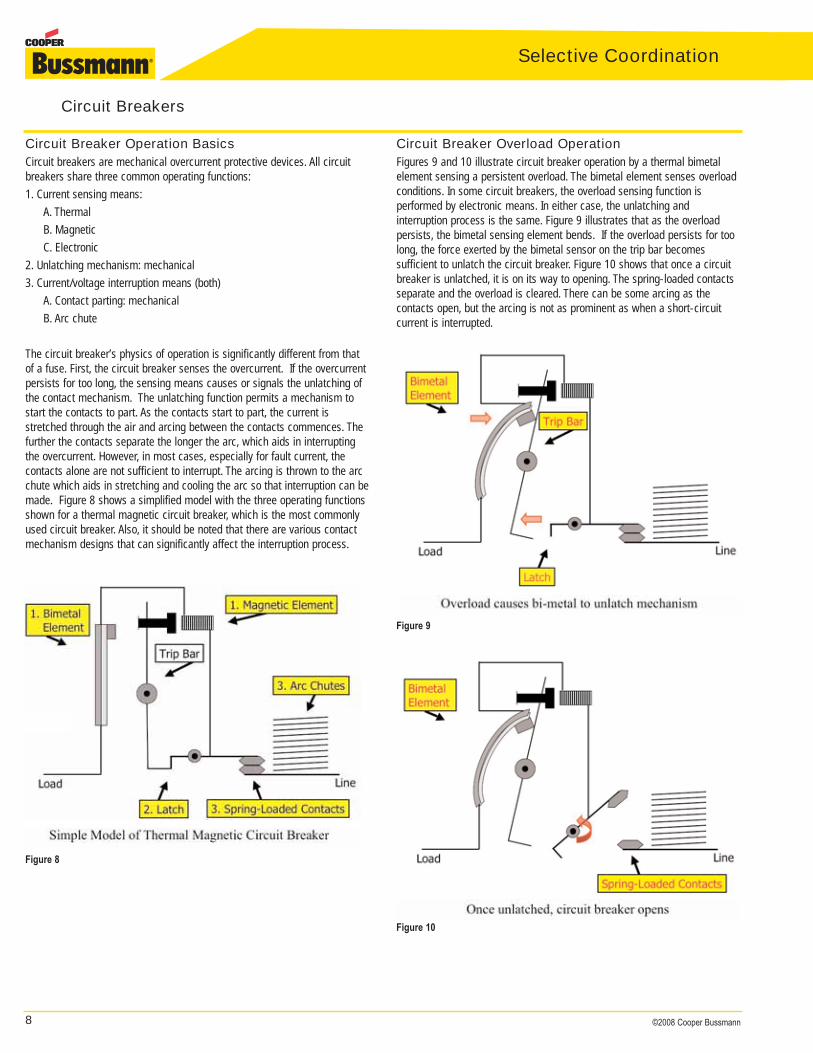
The circuit breaker’s physics of operation is significantly different from thatof a fuse. First, the circuit breaker senses the overcurrent. If the overcurrentpersists for too long, the sensing means causes or signals the unlatching ofthe contact mechanism. The unlatching function permits a mechanism tostart the contacts to part. As the contacts start to part, the current isstretched through the air and arcing between the contacts commences. Thefurther the contacts separate the longer the arc, which aids in interruptingthe overcurrent. However, in most cases, especially for fault current, the contacts alone are not sufficient to interrupt. The arcing is thrown to the arcchute which aids in stretching and cooling the arc so that interruption can bemade. Figure 8 shows a simplified model with the three operating functionsshown for a thermal magnetic circuit breaker, which is the most commonlyused circuit breaker. Also, it should be noted that there are various contactmechanism designs that can significantly affect the interruption process.
Circuit Breaker Overload OperationFigures 9 and 10 illustrate circuit breaker operation by a thermal bimetal element sensing a persistent overload. The bimetal element senses overloadconditions. In some circuit breakers, the overload sensing function is performed by electronic means. In either case, the unlatching and interruption process is the same. Figure 9 illustrates that as the overload persists, the bimetal sensing element bends. If the overload persists for toolong, the force exerted by the bimetal sensor on the trip bar becomes sufficient to unlatch the circuit breaker. Figure 10 shows that once a circuitbreaker is unlatched, it is on its way to opening. The spring-loaded contactsseparate and the overload is cleared. There can be some arcing as the contacts open, but the arcing is not as prominent as when a short-circuitcurrent is interrupted.
Circuit Breakers
Figure 8
Figure 9
Figure 10
9©2008 Cooper Bussmann
Circuit Breakers
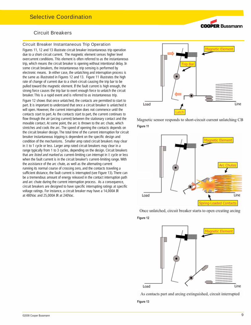
Circuit Breaker Instantaneous Trip OperationFigures 11, 12 and 13 illustrate circuit breaker instantaneous trip operationdue to a short-circuit current. The magnetic element senses higher levelovercurrent conditions. This element is often referred to as the instantaneoustrip, which means the circuit breaker is opening without intentional delay. Insome circuit breakers, the instantaneous trip sensing is performed by electronic means. In either case, the unlatching and interruption process isthe same as illustrated in Figures 12 and 13. Figure 11 illustrates the highrate of change of current due to a short-circuit causing the trip bar to bepulled toward the magnetic element. If the fault current is high enough, thestrong force causes the trip bar to exert enough force to unlatch the circuitbreaker. This is a rapid event and is referred to as instantaneous trip.Figure 12 shows that once unlatched, the contacts are permitted to start topart. It is important to understand that once a circuit breaker is unlatched itwill open. However, the current interruption does not commence until thecontacts start to part. As the contacts start to part, the current continues toflow through the air (arcing current) between the stationary contact and themovable contact. At some point, the arc is thrown to the arc chute, whichstretches and cools the arc. The speed of opening the contacts depends onthe circuit breaker design. The total time of the current interruption for circuitbreaker instantaneous tripping is dependent on the specific design and condition of the mechanisms. Smaller amp rated circuit breakers may clearin 1⁄2 to 1 cycle or less. Larger amp rated circuit breakers may clear in arange typically from 1 to 3 cycles, depending on the design. Circuit breakersthat are listed and marked as current-limiting can interrupt in 1⁄2 cycle or lesswhen the fault current is in the circuit breaker’s current-limiting range. Withthe assistance of the arc chute, as well as the alternating current running its normal course of crossing zero, and the contacts traveling a sufficient distance, the fault current is interrupted (see Figure 13). There canbe a tremendous amount of energy released in the contact interruption pathand arc chute during the current interruption process. As a consequence,circuit breakers are designed to have specific interrupting ratings at specificvoltage ratings. For instance, a circuit breaker may have a 14,000A IR at 480Vac and 25,000A IR at 240Vac.
Figure 11
Figure 12
Figure 13
Selective Coordination
10 ©2008 Cooper Bussmann
Selective Coordination
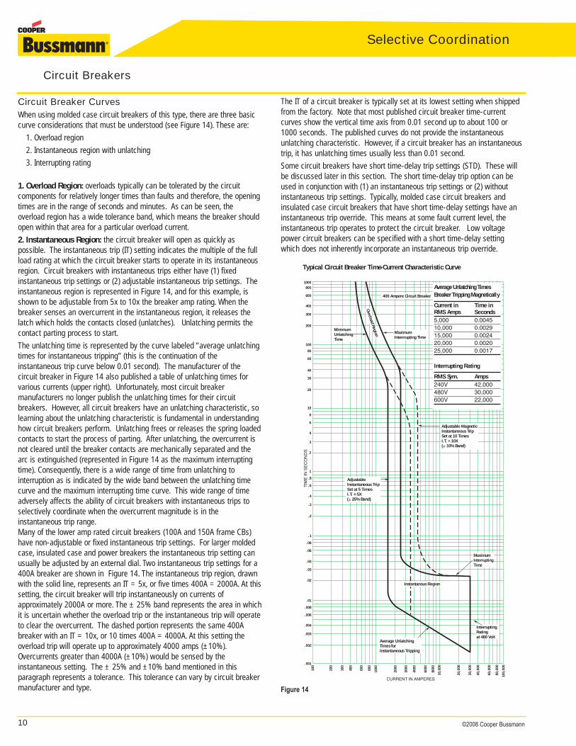
Circuit Breaker CurvesWhen using molded case circuit breakers of this type, there are three basiccurve considerations that must be understood (see Figure 14). These are:
1. Overload region2. Instantaneous region with unlatching3. Interrupting rating
1. Overload Region: overloads typically can be tolerated by the circuit components for relatively longer times than faults and therefore, the openingtimes are in the range of seconds and minutes. As can be seen, the overload region has a wide tolerance band, which means the breaker shouldopen within that area for a particular overload current.2. Instantaneous Region: the circuit breaker will open as quickly as possible. The instantaneous trip (IT) setting indicates the multiple of the fullload rating at which the circuit breaker starts to operate in its instantaneousregion. Circuit breakers with instantaneous trips either have (1) fixed instantaneous trip settings or (2) adjustable instantaneous trip settings. Theinstantaneous region is represented in Figure 14, and for this example, isshown to be adjustable from 5x to 10x the breaker amp rating. When thebreaker senses an overcurrent in the instantaneous region, it releases thelatch which holds the contacts closed (unlatches). Unlatching permits thecontact parting process to start.The unlatching time is represented by the curve labeled “average unlatchingtimes for instantaneous tripping” (this is the continuation of the instantaneous trip curve below 0.01 second). The manufacturer of the circuit breaker in Figure 14 also published a table of unlatching times forvarious currents (upper right). Unfortunately, most circuit breaker manufacturers no longer publish the unlatching times for their circuit breakers. However, all circuit breakers have an unlatching characteristic, solearning about the unlatching characteristic is fundamental in understandinghow circuit breakers perform. Unlatching frees or releases the spring loadedcontacts to start the process of parting. After unlatching, the overcurrent isnot cleared until the breaker contacts are mechanically separated and thearc is extinguished (represented in Figure 14 as the maximum interruptingtime). Consequently, there is a wide range of time from unlatching to interruption as is indicated by the wide band between the unlatching timecurve and the maximum interrupting time curve. This wide range of timeadversely affects the ability of circuit breakers with instantaneous trips toselectively coordinate when the overcurrent magnitude is in the instantaneous trip range.Many of the lower amp rated circuit breakers (100A and 150A frame CBs)have non-adjustable or fixed instantaneous trip settings. For larger moldedcase, insulated case and power breakers the instantaneous trip setting canusually be adjusted by an external dial. Two instantaneous trip settings for a400A breaker are shown in Figure 14. The instantaneous trip region, drawnwith the solid line, represents an IT = 5x, or five times 400A = 2000A. At thissetting, the circuit breaker will trip instantaneously on currents of approximately 2000A or more. The ± 25% band represents the area in whichit is uncertain whether the overload trip or the instantaneous trip will operateto clear the overcurrent. The dashed portion represents the same 400Abreaker with an IT = 10x, or 10 times 400A = 4000A. At this setting theoverload trip will operate up to approximately 4000 amps (±10%).Overcurrents greater than 4000A (±10%) would be sensed by the instantaneous setting. The ± 25% and ±10% band mentioned in this paragraph represents a tolerance. This tolerance can vary by circuit breakermanufacturer and type.
The IT of a circuit breaker is typically set at its lowest setting when shippedfrom the factory. Note that most published circuit breaker time-currentcurves show the vertical time axis from 0.01 second up to about 100 or1000 seconds. The published curves do not provide the instantaneousunlatching characteristic. However, if a circuit breaker has an instantaneoustrip, it has unlatching times usually less than 0.01 second.Some circuit breakers have short time-delay trip settings (STD). These willbe discussed later in this section. The short time-delay trip option can beused in conjunction with (1) an instantaneous trip settings or (2) withoutinstantaneous trip settings. Typically, molded case circuit breakers and insulated case circuit breakers that have short time-delay settings have aninstantaneous trip override. This means at some fault current level, theinstantaneous trip operates to protect the circuit breaker. Low voltagepower circuit breakers can be specified with a short time-delay settingwhich does not inherently incorporate an instantaneous trip override.
Circuit Breakers
CURRENT IN AMPERES
100
200
300
400
600
800
1000
2000
3000
4000
6000
8000
10,0
00
20,0
00
30,0
00
40,0
00
60,0
00
80,0
00
100,
000
600
400
300
200
100
80
60
40
30
20
10
8
6
4
3
2
1
.8
.6
.4
.3
.2
.1
.08
.04
.06
.03
.02
.01
TIM
E IN
SE
CO
ND
S
8001000
.008
.006
.004
.003
.002
.001
InterruptingRatingat 480 Volt
Instantanous Region
MinimumUnlatchingTime
Overload Region MaximumInterrrupting Time
400 Ampere Circuit Breaker
AdjustableInstantaneous TripSet at 5 TimesI.T. = 5X(± 25% Band)
Adjustable MagneticInstantaneous TripSet at 10 TimesI.T. = 10X(± 10% Band)
MaximumInterruptingTime
Average UnlatchingTimes for Instantaneous Tripping
Typical Circuit Breaker Time-Current Characteristic Curve
Average Unlatching TimesBreaker Tripping Magnetically
Current in Time in RMS Amps Seconds5,000 0.004510,000 0.002915,000 0.002420,000 0.002025,000 0.0017
Interrupting Rating
RMS Sym. Amps240V 42,000480V 30,000600V 22,000
Figure 14
11©2008 Cooper Bussmann
Interrupting Rating: The interrupting rating is represented on the drawingby a vertical line at the right end of the curve. The interrupting rating for circuit breakers varies based on the voltage level; see the interrupting ratingtable in Figure 14 which lists the interrupting ratings for this specific circuitbreaker. For coordination purposes, the vertical line is often drawn at thefault current level in lieu of the interrupting rating (if the interrupting rating isgreater than the available short-circuit current). However, if the fault currentis above the interrupting rating, a misapplication and violation of NEC® 110.9is evident. In Figure 14, the circuit breaker interrupting rating at 480 volts is30,000 amps. The marked interrupting rating on a three-pole circuit breakeris a three-pole rating and not a single-pole rating (refer to Single-PoleInterrupting Capability section for more information).
Achieving Selective Coordination with Low VoltageCircuit BreakersTo achieve selective coordination with low voltage circuit breakers, no overlap of time-current curves (including the unlatching time) is permitted upto the available short-circuit current. The ability of circuit breakers toachieve coordination depends upon the type of circuit breakers selected;amp ratings, settings and options of the circuit breakers, and the availableshort-circuit currents. The type of circuit breaker selected could be one ofthree types: circuit breakers with instantaneous trips; circuit breakers withshort time-delay but incorporating instantaneous overrides; or circuit breakers with short time-delays (no instantaneous override). In this section,various alternative circuit breaker schemes will be discussed in relation toassessing for selective coordination.
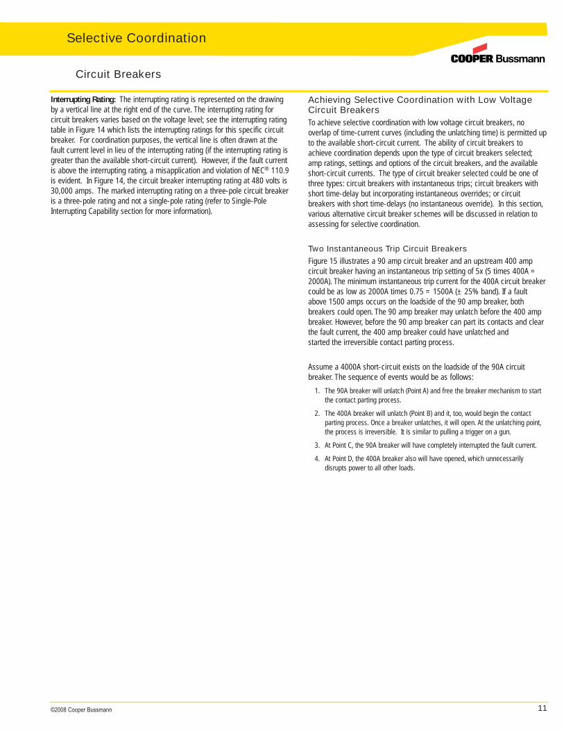
Two Instantaneous Trip Circuit BreakersFigure 15 illustrates a 90 amp circuit breaker and an upstream 400 amp circuit breaker having an instantaneous trip setting of 5x (5 times 400A =2000A). The minimum instantaneous trip current for the 400A circuit breakercould be as low as 2000A times 0.75 = 1500A (± 25% band). If a faultabove 1500 amps occurs on the loadside of the 90 amp breaker, both breakers could open. The 90 amp breaker may unlatch before the 400 ampbreaker. However, before the 90 amp breaker can part its contacts and clearthe fault current, the 400 amp breaker could have unlatched and started the irreversible contact parting process.
Assume a 4000A short-circuit exists on the loadside of the 90A circuit breaker. The sequence of events would be as follows:
1. The 90A breaker will unlatch (Point A) and free the breaker mechanism to startthe contact parting process.
2. The 400A breaker will unlatch (Point B) and it, too, would begin the contact parting process. Once a breaker unlatches, it will open. At the unlatching point,the process is irreversible. It is similar to pulling a trigger on a gun.
3. At Point C, the 90A breaker will have completely interrupted the fault current.
4. At Point D, the 400A breaker also will have opened, which unnecessarily disrupts power to all other loads.
Circuit Breakers
Selective Coordination
12 ©2008 Cooper Bussmann
Selective Coordination
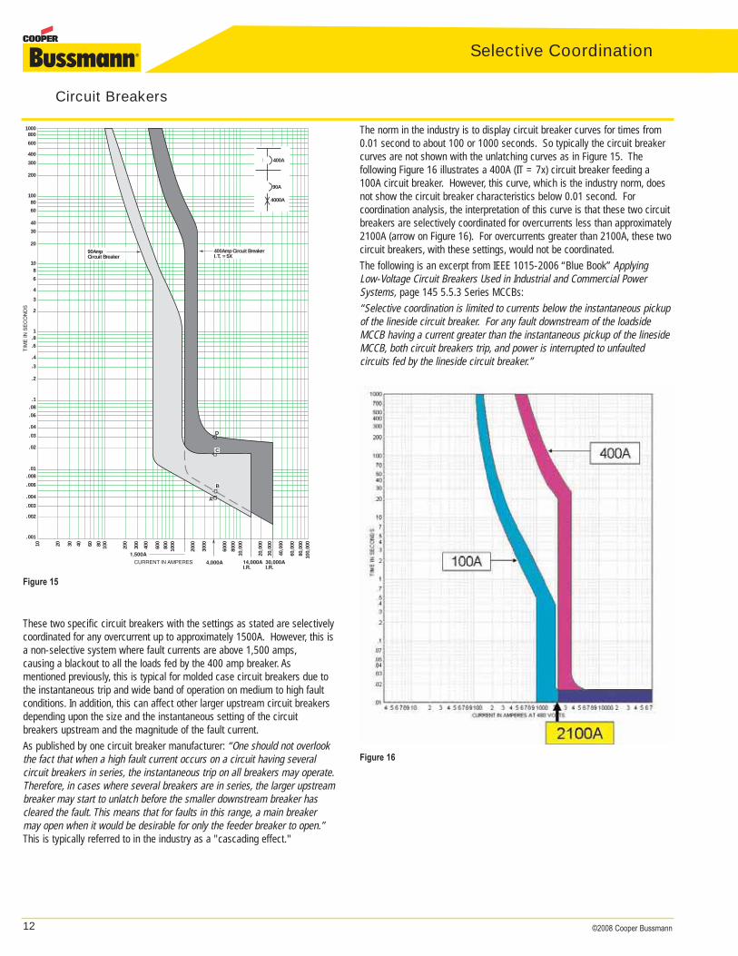
These two specific circuit breakers with the settings as stated are selectivelycoordinated for any overcurrent up to approximately 1500A. However, this isa non-selective system where fault currents are above 1,500 amps,causing a blackout to all the loads fed by the 400 amp breaker. As mentioned previously, this is typical for molded case circuit breakers due tothe instantaneous trip and wide band of operation on medium to high faultconditions. In addition, this can affect other larger upstream circuit breakersdepending upon the size and the instantaneous setting of the circuit breakers upstream and the magnitude of the fault current.As published by one circuit breaker manufacturer: “One should not overlookthe fact that when a high fault current occurs on a circuit having several circuit breakers in series, the instantaneous trip on all breakers may operate.Therefore, in cases where several breakers are in series, the larger upstreambreaker may start to unlatch before the smaller downstream breaker hascleared the fault. This means that for faults in this range, a main breakermay open when it would be desirable for only the feeder breaker to open.”This is typically referred to in the industry as a "cascading effect."
The norm in the industry is to display circuit breaker curves for times from0.01 second to about 100 or 1000 seconds. So typically the circuit breakercurves are not shown with the unlatching curves as in Figure 15. The following Figure 16 illustrates a 400A (IT = 7x) circuit breaker feeding a100A circuit breaker. However, this curve, which is the industry norm, doesnot show the circuit breaker characteristics below 0.01 second. For coordination analysis, the interpretation of this curve is that these two circuitbreakers are selectively coordinated for overcurrents less than approximately2100A (arrow on Figure 16). For overcurrents greater than 2100A, these twocircuit breakers, with these settings, would not be coordinated.The following is an excerpt from IEEE 1015-2006 “Blue Book” Applying Low-Voltage Circuit Breakers Used in Industrial and Commercial PowerSystems, page 145 5.5.3 Series MCCBs:“Selective coordination is limited to currents below the instantaneous pickupof the lineside circuit breaker. For any fault downstream of the loadsideMCCB having a current greater than the instantaneous pickup of the linesideMCCB, both circuit breakers trip, and power is interrupted to unfaulted circuits fed by the lineside circuit breaker.”
Circuit Breakers
80
TIM
E IN
SE
CO
ND
S
•�•�
•�
•�
CURRENT IN AMPERES
1,500A
A
C
D
B
30,000AI.R.
14,000AI.R.
90AmpCircuit Breaker
400Amp Circuit BreakerI.T. = 5X
400A
90A
4000A
4,000A
1000
600
400
300
200
100
60
40
30
20
108
6
4
3
2
1.8.6
.4
.3
.2
.1.08
.04
.06
.03
.02
.01
800
.008
.004
.006
.003
.002
.001
3010 20 40 60 80 100
200
300
400
600
800
1000
2000
3000
6000
8000
10,0
00
20,0
00
30,0
00
40,0
00
60,0
00
80,0
0010
0,00
0
Figure 15
Figure 16
13©2008 Cooper Bussmann
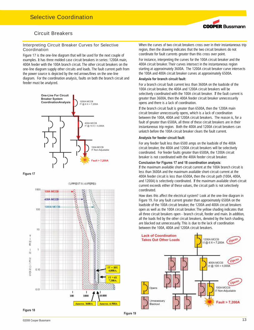
Interpreting Circuit Breaker Curves for SelectiveCoordinationFigure 17 is the one-line diagram that will be used for the next couple ofexamples. It has three molded case circuit breakers in series: 1200A main,400A feeder with the 100A branch circuit. The other circuit breakers on theone-line diagram supply other circuits and loads. The fault current path fromthe power source is depicted by the red arrows/lines on the one-line diagram. For the coordination analysis, faults on both the branch circuit andfeeder must be analyzed.
When the curves of two circuit breakers cross over in their instantaneous tripregion, then the drawing indicates that the two circuit breakers do not coordinate for fault currents greater than this cross over point.For instance, interpreting the curves for the 100A circuit breaker and the400A circuit breaker. Their curves intersect in the instantaneous region starting at approximately 3600A. The 1200A circuit breaker curve intersectsthe 100A and 400A circuit breaker curves at approximately 6500A.Analysis for branch circuit fault:
For a branch circuit fault current less than 3600A on the loadside of the 100A circuit breaker, the 400A and 1200A circuit breakers will be selectively coordinated with the 100A circuit breaker. If the fault current is greater than 3600A, then the 400A feeder circuit breaker unnecessarily opens and there is a lack of coordination.If the branch circuit fault is greater than 6500A, then the 1200A main circuit breaker unnecessarily opens, which is a lack of coordination between the 100A, 400A and 1200A circuit breakers. The reason is, for a fault of greater than 6500A, all three of these circuit breakers are in their instantaneous trip region. Both the 400A and 1200A circuit breakers can unlatch before the 100A circuit breaker clears the fault current.
Analysis for feeder circuit fault:
For any feeder fault less than 6500 amps on the loadside of the 400A circuit breaker, the 400A and 1200A circuit breakers will be selectively coordinated. For feeder faults greater than 6500A, the 1200A circuit breaker is not coordinated with the 400A feeder circuit breaker.Conclusion for Figures 17 and 18 coordination analysis:If the maximum available short-circuit current at the 100A branch circuit isless than 3600A and the maximum available short-circuit current at the400A feeder circuit is less than 6500A, then the circuit path (100A, 400A,and 1200A) is selectively coordinated. If the maximum available short-circuitcurrent exceeds either of these values, the circuit path is not selectively coordinated.How does this affect the electrical system? Look at the one-line diagram inFigure 19. For any fault current greater than approximately 6500A on theloadside of the 100A circuit breaker, the 1200A and 400A circuit breakersopen as well as the 100A circuit breaker. The yellow shading indicates thatall three circuit breakers open - branch circuit, feeder and main. In addition,all the loads fed by the other circuit breakers, denoted by the hash shading,are blacked out unnecessarily. This is due to the lack of coordinationbetween the 100A, 400A and 1200A circuit breakers.
Circuit Breakers
Figure 17
Figure 18Figure 19
Selective Coordination
14 ©2008 Cooper Bussmann
Selective Coordination
Circuit Breakers
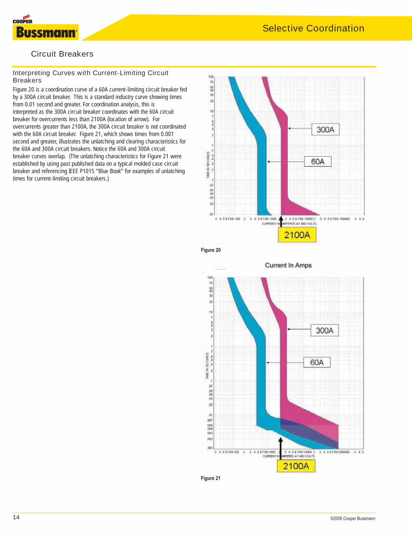
Interpreting Curves with Current-Limiting CircuitBreakersFigure 20 is a coordination curve of a 60A current-limiting circuit breaker fedby a 300A circuit breaker. This is a standard industry curve showing timesfrom 0.01 second and greater. For coordination analysis, this is interpreted as the 300A circuit breaker coordinates with the 60A circuitbreaker for overcurrents less than 2100A (location of arrow). For overcurrents greater than 2100A, the 300A circuit breaker is not coordinatedwith the 60A circuit breaker. Figure 21, which shows times from 0.001 second and greater, illustrates the unlatching and clearing characteristics forthe 60A and 300A circuit breakers. Notice the 60A and 300A circuit breaker curves overlap. (The unlatching characteristics for Figure 21 wereestablished by using past published data on a typical molded case circuitbreaker and referencing IEEE P1015 “Blue Book” for examples of unlatchingtimes for current-limiting circuit breakers.)
Figure 21
Figure 20
15©2008 Cooper Bussmann
General note: Many 100A and 150A frame circuit breakers have fixed instantaneous trips which are not adjustable. For these circuit breakers thefixed instantaneous trip will typically “pickup” between 800 to 1300 amps.For adjustable circuit breakers, the instantaneous trip adjustment range canvary depending upon frame size, manufacturer and type.Typically adjustable settings of 4 to 10 times the amp rating are available(check manufacturers’ data for specific circuit breakers). Circuit breakers aregenerally shipped from the factory at the lowest adjustable instantaneoustrip setting. This setting should not be changed without a detailed analysis ofhow it will affect the overall electrical system protection, coordination andpersonnel safety.
With the Tolerances This second example of the easy method will include the instantaneous trippickup tolerance band. This is a more accurate determination. The tolerance is ±. However, for this simple method, it is only necessary to consider the negative tolerance.Information needed for each feeder and main circuit breaker (CB):
1. CB’s amp rating or amp setting2. CB’s instantaneous trip setting (IT)
• Most feeder and main CBs have adjustable IT settings with varying ranges from 3 to 12X
• Some CBs have fixed IT settings • Some newer feeder CBs have fixed IT set at 20X
3. CB’s IT pickup percentage (%) tolerance 4. If CB IT pickup % tolerance is not known, here are some worst case*
practical rules of thumb:• Thermal magnetic (high trip setting): ± 20%• Thermal magnetic (low trip setting): ± 25%• Electronic trip: ± 10%
* Based on numerous samples taken from leading CB manufacturers’ data.
Equation:ISCA Coordination < (CB amp rating x IT setting) x (1 -% tolerance**)100
ISCA Coordination is the maximum short-circuit overcurrent at which the circuit breaker will selectively coordinate with downstream circuit breakers.** Use actual CB % tolerance, otherwise use assumed worst case % tolerances
CB Coordination: Simplified Method Without Time-Current Curves It is not necessary to draw the curves to assess circuit breaker coordinationwhen the circuit breakers are of the instantaneous trip type. There is a simple method to determine the highest short-circuit current or short-circuitamps (ISCA) at which circuit breakers will selectively coordinate. Simply multiply the instantaneous trip setting by the circuit breaker amp rating. Theproduct of a circuit breaker’s instantaneous trip setting and its amp rating isthe approximate point at which a circuit breaker enters its instantaneous tripregion. This method is applicable to the instantaneous trip only, not theoverload region. However, in most cases, the circuit breaker overloadregions will coordinate. This simple method can be used as a first test inassessing if a system is selectively coordinated. There may be other meansto determine higher values of ISCA where circuit breakers selectively coordinate (such as manufacturer’s tables), but this is a practical, easymethod.As explained previously, there is a tolerance where the instantaneous trip initially picks up. A vertical band depicts the instantaneous trip pickup tolerance. The following will illustrate this simple method ignoring the tolerances. Then the simple method with the tolerances will be illustrated.
Ignoring the Tolerances For this first example of the easy method, we will ignore the instantaneoustrip pickup tolerance band. However, the fault values where the circuitbreakers are selectively coordinated will differ from the same example whenusing the curves in the previous section.Using the simple method for the example in Figure 17, the 400A circuitbreaker has its instantaneous trip (IT) set at 10 times its amp rating (10x).Therefore for fault currents above 10 x 400A = 4000 amps, the 400A circuitbreaker will unlatch in its instantaneous trip region, thereby opening. Thesame could be determined for the 1200A circuit breaker, which has itsinstantaneous trip set at 6x its amp rating. Therefore, for fault currents above7200 amps (6 x 1200 = 7200A), the 1200A circuit breaker unlatches in itsinstantaneous trip region, thereby opening.The coordination analysis of the circuit breakers merely requires knowingwhat the numbers mean.Analysis for branch circuit faults: In Figure 17, for a branch circuit fault less than 4000A on the loadside of the 100A circuit breaker, the 400A and 1200A circuit breakers will be selectively coordinated with the 100A circuit breaker. If the fault current is greater than 4000A, then the 400A feeder circuit breaker unnecessarily opens and there is a lack of coordination.If the branch circuit fault is greater than 7200A, then the 1200A main circuit breaker may unnecessarily open, which is a lack of coordination between the 100A, 400A and 1200A circuit breakers. The reason is: for a fault of greater than 7200A, all three of these circuit breakers are in their instantaneous trip region. Both the 400A and 1200A circuit breakers can unlatch before the 100A circuit breaker clears the fault current.For faults on the loadside of the 400A circuit breaker:For any feeder fault less than 7200 amps on the loadside of the 400A circuit breaker, the 400A and 1200A circuit breakers will be selectively coordinated. For feeder faults greater than 7200A, the 1200A circuit breaker is not coordinated with the 400A feeder circuit breaker.
Circuit Breakers
Selective Coordination
16 ©2008 Cooper Bussmann
Selective Coordination
Circuit Breakers
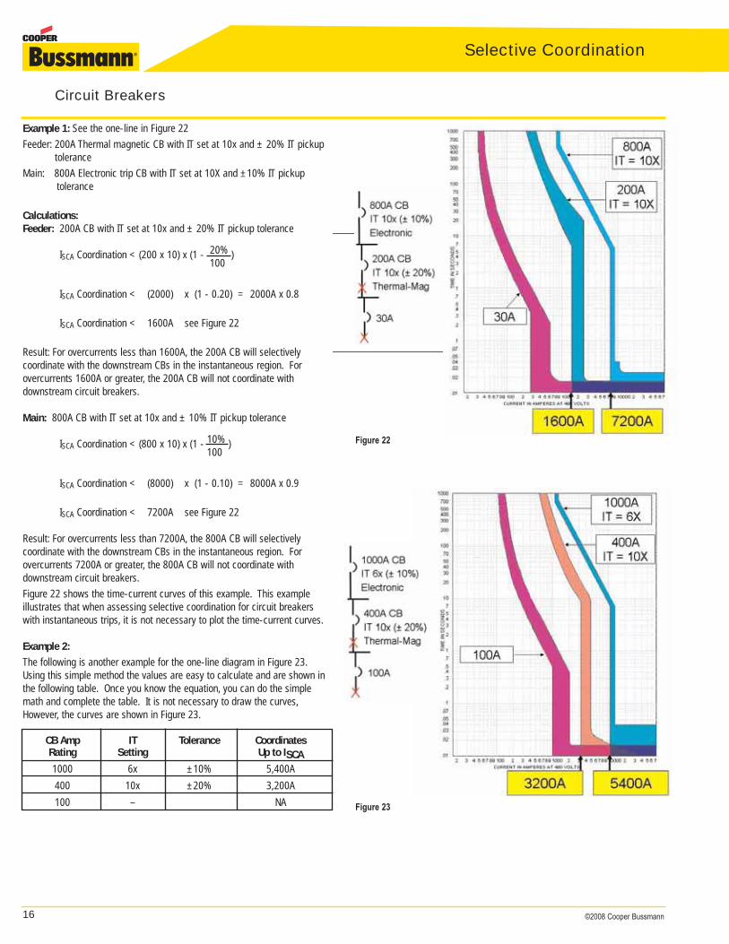
Example 1: See the one-line in Figure 22 Feeder: 200A Thermal magnetic CB with IT set at 10x and ± 20% IT pickup
toleranceMain: 800A Electronic trip CB with IT set at 10X and ±10% IT pickup
tolerance
Calculations:Feeder: 200A CB with IT set at 10x and ± 20% IT pickup tolerance
ISCA Coordination < (200 x 10) x (1 - 20% )100
ISCA Coordination < (2000) x (1 - 0.20) = 2000A x 0.8
ISCA Coordination < 1600A see Figure 22
Result: For overcurrents less than 1600A, the 200A CB will selectively coordinate with the downstream CBs in the instantaneous region. For overcurrents 1600A or greater, the 200A CB will not coordinate with downstream circuit breakers.
Main: 800A CB with IT set at 10x and ± 10% IT pickup tolerance
ISCA Coordination < (800 x 10) x (1 - 10% )100
ISCA Coordination < (8000) x (1 - 0.10) = 8000A x 0.9
ISCA Coordination < 7200A see Figure 22
Result: For overcurrents less than 7200A, the 800A CB will selectively coordinate with the downstream CBs in the instantaneous region. For overcurrents 7200A or greater, the 800A CB will not coordinate with downstream circuit breakers.Figure 22 shows the time-current curves of this example. This exampleillustrates that when assessing selective coordination for circuit breakerswith instantaneous trips, it is not necessary to plot the time-current curves.
Example 2:
The following is another example for the one-line diagram in Figure 23.Using this simple method the values are easy to calculate and are shown inthe following table. Once you know the equation, you can do the simplemath and complete the table. It is not necessary to draw the curves,However, the curves are shown in Figure 23.
Figure 23
Figure 22
CB Amp IT Tolerance CoordinatesRating Setting Up to ISCA1000 6x ±10% 5,400A400 10x ±20% 3,200A100 – NA
17©2008 Cooper Bussmann
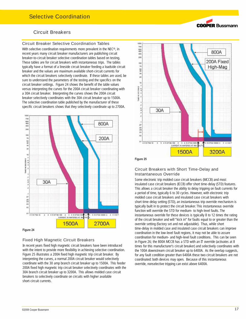
Circuit Breaker Selective Coordination TablesWith selective coordination requirements more prevalent in the NEC®, inrecent years many circuit breaker manufacturers are publishing circuitbreaker-to-circuit breaker selective coordination tables based on testing.These tables are for circuit breakers with instantaneous trips. The tables typically have a format of a lineside circuit breaker feeding a loadside circuitbreaker and the values are maximum available short-circuit currents forwhich the circuit breakers selectively coordinate. If these tables are used, besure to understand the parameters of the testing and the specifics on thecircuit breaker settings. Figure 24 shows the benefit of the table values versus interpreting the curves for the 200A circuit breaker coordinating witha 30A circuit breaker. Interpreting the curves shows the 200A circuit breaker selectively coordinates with the 30A circuit breaker up to 1500A.The selective coordination table published by the manufacturer of these specific circuit breakers shows that they selectively coordinate up to 2700A.
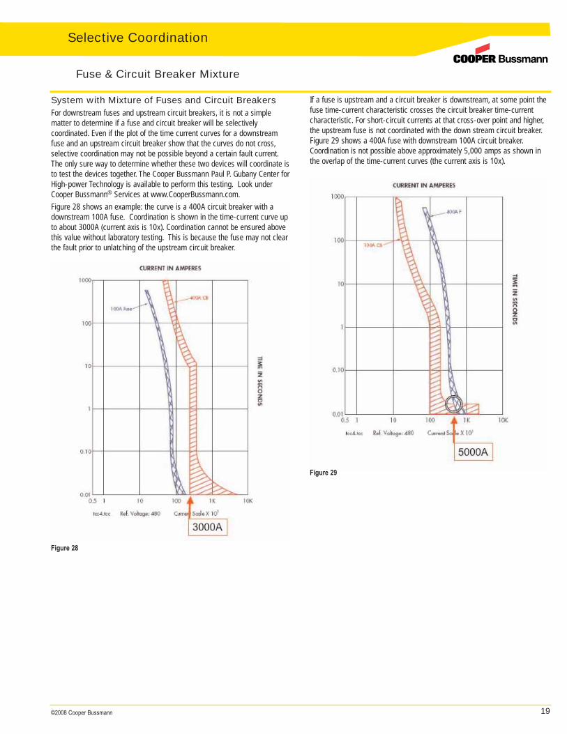
Fixed High Magnetic Circuit BreakersIn recent years fixed high magnetic circuit breakers have been introducedwith the intent to provide more flexibility in achieving selective coordination.Figure 25 illustrates a 200A fixed high magnetic trip circuit breaker. By interpreting the curves, a normal 200A circuit breaker would selectivelycoordinate with the 30 amp branch circuit breaker up to 1500A. This feeder200A fixed high magnetic trip circuit breaker selectively coordinates with the30A branch circuit breaker up to 3200A. This allows molded case circuitbreakers to selectively coordinate on circuits with higher available short-circuit currents.
Circuit Breakers with Short Time-Delay andInstantaneous OverrideSome electronic trip molded case circuit breakers (MCCB) and most insulated case circuit breakers (ICCB) offer short time-delay (STD) features.This allows a circuit breaker the ability to delay tripping on fault currents fora period of time, typically 6 to 30 cycles. However, with electronic trip molded case circuit breakers and insulated case circuit breakers with short time-delay setting (STD), an instantaneous trip override mechanism istypically built in to protect the circuit breaker. This instantaneous overridefunction will override the STD for medium- to high-level faults. The instantaneous override for these devices is typically 8 to 12 times the ratingof the circuit breaker and will “kick in” for faults equal to or greater than theoverride setting (factory set and not adjustable). Thus, while short time-delay in molded case and insulated case circuit breakers can improve coordination in the low-level fault regions, it may not be able to assure coordination for medium- and high-level fault conditions. This can be seenin Figure 26; the 800A MCCB has a STD with an IT override (activates at 8times for this manufacturer’s circuit breaker) and selectively coordinates withthe 100A downstream circuit breaker up to 6400A. As the overlap suggests,for any fault condition greater than 6400A these two circuit breakers are notcoordinated: both devices may open. Because of this instantaneous override, nonselective tripping can exist above 6400A.
Circuit Breakers
Figure 24
Figure 25
Selective Coordination

18 ©2008 Cooper Bussmann
Selective Coordination
Low Voltage Power Circuit Breakers (LVPCB) withShort Time-DelayShort time-delay, with settings from 6 to 30 cycles, is also available on lowvoltage power circuit breakers. However, with low voltage power circuitbreakers an instantaneous override is not required. Thus, low voltage powercircuit breakers with short time-delay can “hold on” to faults for up to 30cycles. Figure 27 illustrates a 30A molded case circuit breaker fed by a200A LVPCB and 800A LVPCB. The 200A and 800A circuit breakers haveshort time settings that provide selective coordination. The 200A circuitbreaker has a STD set at 6 cycles and the 800A circuit breaker has a STDset at 20 cycles. The curves can be plotted to ensure the circuit breakersdo not intersect at any point. If there is intersection, investigate differentshort time-delay settings. The interrupting ratings for the circuit breakerswith short time-delay may be less than the same circuit breaker with aninstantaneous trip.
Summary for Circuit Breaker Selective CoordinationIt is possible to design electrical systems with circuit breakers and achieveselective coordination. It requires analysis and proper choice of circuitbreaker types and options. In most cases it is necessary to calculate theavailable short-circuit currents at the point of application of each circuitbreaker, a coordination analysis (plotting of curves) and proper interpretationof the results for each circuit path. Following is a list that provides methodsfor using circuit breakers to achieve selective coordination, with the leastexpensive options appearing at the top:
1. MCCBs and ICCBs with instantaneous trip settings2. Circuit breakers coordinated to manufacturer’s tested coordination
tables. These tables can enable circuit breakers to coordinate for fault currents higher than shown on the time-current curves.
3. MCCBs with fixed high magnetic trip or larger frame size may allow higher instantaneous trip
4. CBs with short time-delay having instantaneous trip override:• MCCBs and ICCBs with short time-delay settings have an instantaneous
trip override that opens the CB instantaneously for higher fault currents (8x to12x amp rating)
• ICCBs may have higher instantaneous override settings than MCCBs5. LVPCBs with short time-delay (with no instantaneous override)
Notes:• The instantaneous trip of upstream circuit breakers must be greater than
the available short-circuit current for alternatives 1, 3, and 4• Some options may require larger frame size or different type CBs• Exercise, maintenance and testing should be performed periodically or
after fault interruption to retain proper clearing times and the coordination scheme
In alternatives 1 through 4, if selective coordination can be achieved, it is jobor application specific; i.e., the designer must do the analysis for each application or job. If the available short-circuit current increases due to system changes, the selective coordination may no longer be valid. Duringinstallation, the contractor must set the circuit breakers correctly.
Circuit Breakers
Figure 26 Figure 27
19©2008 Cooper Bussmann
Figure 28
Figure 29
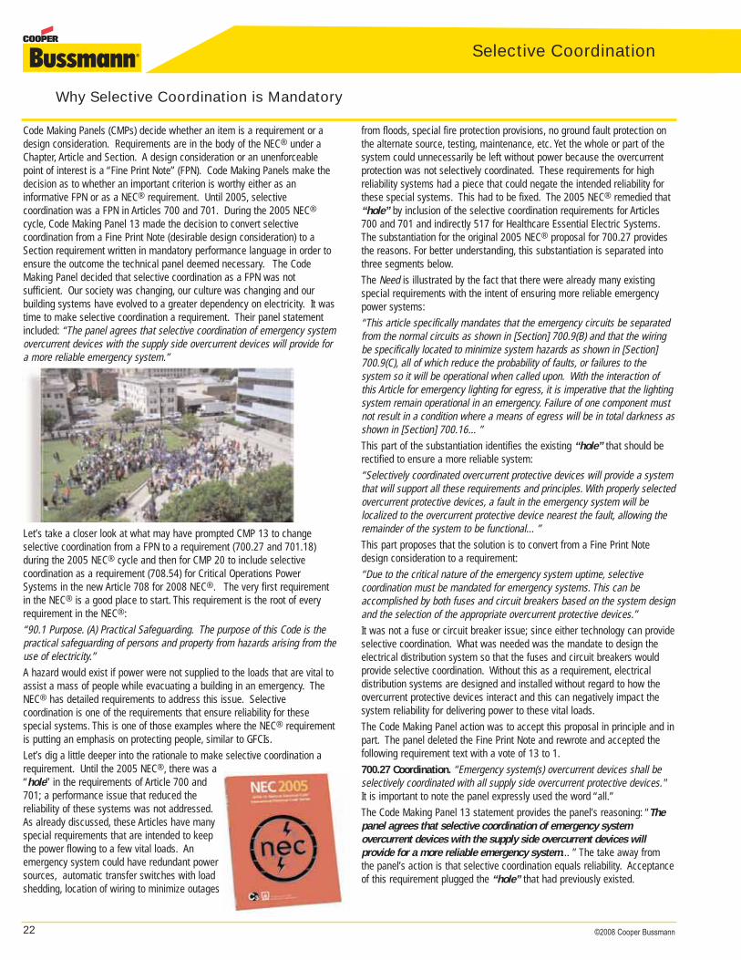
If a fuse is upstream and a circuit breaker is downstream, at some point thefuse time-current characteristic crosses the circuit breaker time-currentcharacteristic. For short-circuit currents at that cross-over point and higher,the upstream fuse is not coordinated with the down stream circuit breaker.Figure 29 shows a 400A fuse with downstream 100A circuit breaker.Coordination is not possible above approximately 5,000 amps as shown inthe overlap of the time-current curves (the current axis is 10x).
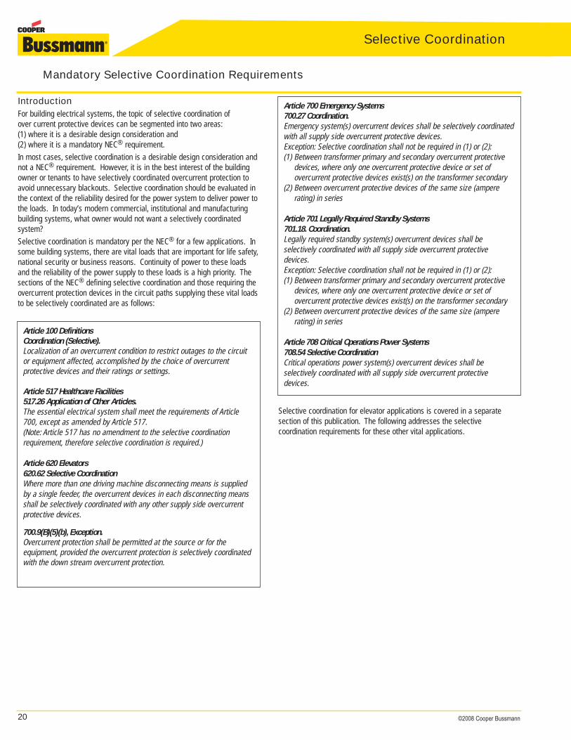
System with Mixture of Fuses and Circuit BreakersFor downstream fuses and upstream circuit breakers, it is not a simple matter to determine if a fuse and circuit breaker will be selectively coordinated. Even if the plot of the time current curves for a downstreamfuse and an upstream circuit breaker show that the curves do not cross,selective coordination may not be possible beyond a certain fault current.The only sure way to determine whether these two devices will coordinate isto test the devices together. The Cooper Bussmann Paul P. Gubany Center forHigh-power Technology is available to perform this testing. Look underCooper Bussmann® Services at www.CooperBussmann.com.Figure 28 shows an example: the curve is a 400A circuit breaker with adownstream 100A fuse. Coordination is shown in the time-current curve upto about 3000A (current axis is 10x). Coordination cannot be ensured abovethis value without laboratory testing. This is because the fuse may not clearthe fault prior to unlatching of the upstream circuit breaker.
Fuse & Circuit Breaker Mixture
Selective Coordination
20 ©2008 Cooper Bussmann
Selective Coordination
IntroductionFor building electrical systems, the topic of selective coordination of over current protective devices can be segmented into two areas:(1) where it is a desirable design consideration and (2) where it is a mandatory NEC® requirement.In most cases, selective coordination is a desirable design consideration andnot a NEC® requirement. However, it is in the best interest of the buildingowner or tenants to have selectively coordinated overcurrent protection toavoid unnecessary blackouts. Selective coordination should be evaluated inthe context of the reliability desired for the power system to deliver power tothe loads. In today’s modern commercial, institutional and manufacturingbuilding systems, what owner would not want a selectively coordinated system?Selective coordination is mandatory per the NEC® for a few applications. Insome building systems, there are vital loads that are important for life safety,national security or business reasons. Continuity of power to these loadsand the reliability of the power supply to these loads is a high priority. Thesections of the NEC® defining selective coordination and those requiring theovercurrent protection devices in the circuit paths supplying these vital loadsto be selectively coordinated are as follows:
Selective coordination for elevator applications is covered in a separate section of this publication. The following addresses the selective coordination requirements for these other vital applications.
Article 100 DefinitionsCoordination (Selective).Localization of an overcurrent condition to restrict outages to the circuitor equipment affected, accomplished by the choice of overcurrent protective devices and their ratings or settings.
Article 517 Healthcare Facilities 517.26 Application of Other Articles.The essential electrical system shall meet the requirements of Article700, except as amended by Article 517.(Note: Article 517 has no amendment to the selective coordinationrequirement, therefore selective coordination is required.)
Article 620 Elevators620.62 Selective CoordinationWhere more than one driving machine disconnecting means is suppliedby a single feeder, the overcurrent devices in each disconnecting meansshall be selectively coordinated with any other supply side overcurrentprotective devices.
700.9(B)(5)(b), Exception.Overcurrent protection shall be permitted at the source or for the equipment, provided the overcurrent protection is selectively coordinatedwith the down stream overcurrent protection.
Article 700 Emergency Systems 700.27 Coordination.Emergency system(s) overcurrent devices shall be selectively coordinatedwith all supply side overcurrent protective devices.Exception: Selective coordination shall not be required in (1) or (2):(1) Between transformer primary and secondary overcurrent protective
devices, where only one overcurrent protective device or set of overcurrent protective devices exist(s) on the transformer secondary
(2) Between overcurrent protective devices of the same size (ampere rating) in series
Article 701 Legally Required Standby Systems701.18. Coordination.Legally required standby system(s) overcurrent devices shall be selectively coordinated with all supply side overcurrent protectivedevices.Exception: Selective coordination shall not be required in (1) or (2):(1) Between transformer primary and secondary overcurrent protective
devices, where only one overcurrent protective device or set of overcurrent protective devices exist(s) on the transformer secondary
(2) Between overcurrent protective devices of the same size (ampere rating) in series
Article 708 Critical Operations Power Systems708.54 Selective Coordination Critical operations power system(s) overcurrent devices shall be selectively coordinated with all supply side overcurrent protectivedevices.
Mandatory Selective Coordination Requirements

21©2008 Cooper Bussmann
Why Selective Coordination is Mandatory: It Fills the Reliability “Hole”The NEC® has mandatory selective coordination requirements for the following systems:
• Emergency Systems- Article 700: 700.27 • Legally Required Standby Systems- Article 701: 701.18• Critical Operations Power Systems- Article 708: 708.54• Healthcare Article 517: 517.26 Required for Essential Electrical Systems
(In addition, selective coordination is required in elevator circuits (620.62), which is not discussedin depth in this section.)
Notice these requirements are not in NEC® Chapters 1 through 4, such asArticles 210 Branch Circuits, 215 Feeders, or 240 Overcurrent Protection.Chapters 1 through 4 requirements pertain generally to all premise electricalinstallations. Instead, these requirements are in Chapters 5 and 7 which areunder special occupancies and special conditions, respectively. Specialattention is given to these systems in the NEC® and they have some uniquerequirements. Articles 700, 701, 708, and 517 are for circuits and systemsthat are intended to deliver reliable power for loads that are vital to life safety, public safety or national security. Reliability for these systems in theabove articles has to be greater than the reliability for the normal systemscovered by Chapters 1 through 4.Reviewing portions of the scopes of these Articles provides further insight.
Article 700: Emergency Systems“700.1 Scope. The provisions of this article apply to the electrical safety ofthe installation, operation, and maintenance…” The inclusion of operationand maintenance indicates that reliability of these systems is very important.For these systems, installation requirements alone are not sufficient. Thesesystems must operate when needed so this Article includes operational andmaintenance requirements. Why? The following statement from the scope is clear: “Essential for safety of human life.” For instance, in times of emergency, these loads are critical to evacuate a mass of people from a building.
Article 708: Critical Operations Power Systems (COPS)“708.1 Scope. FPN No. 1: Critical operations power systems are generallyinstalled in vital infrastructure facilities that, if destroyed or incapacitated,would disrupt national security, the economy, public health or safety; andwhere enhanced electrical infrastructure for continuity of operation has beendeemed necessary by governmental authority.” Due to recent events such as9/11 and Hurricane Katrina, Homeland Security requested that NFPA developelectrical requirements for systems that are vital to the public. The newlycreated Article 708 (COPS) includes requirements, such as selective coordination, that are minimum requirements for electrical systems that areimportant for national security.
Articles 700, 701, 708, and 517 are unique. They have more restrictive minimum requirements (versus the general requirements for normal systems) in order for these systems to provide more reliable power to vitalloads. Selective coordination is one of the requirements that support higherreliability. To make the point, here are just a few of the more restrictive minimum requirements in Article 700:
• Periodic testing, maintenance and record retention• Alternate power sources• Wiring from emergency source to emergency loads shall be separate
from all other wiring• Special fire protection for wiring • Locating wiring to avoid outage due to physical damage during fires,
floods, vandalism, etc.• Automatic transfer switches (ATS) with sophisticated sensors,
monitors and controls• Separate ATSs and load segmenting (emergency, legally required
standby and optional standby) with sophisticated load shedding, ifrequired
Article 708 (COPS) also has a similar list of restrictive requirements with theintent of providing a reliable power system.
Why have these special, more restrictive requirements? The reason thesearticles for special systems exist is that the electrical industry, the standardmaking bodies, the technical code panel members and Homeland Securityfeel special rules are needed to ensure minimum requirements for deliveringreliable power for designated vital loads. To better understand why we havemore restrictive requirements, focus on the loads that are being served bythese special systems. There are a few vital loads that pertain to life safety,public safety and national security. For instance, 700.1 Scope FPN states “FPN No. 3: Emergency systems are generally installed in places of assemblywhere artificial illumination is required for safe exiting and for panic controlin buildings subject to occupancy by large numbers of persons, such ashotels, theaters, sports arenas, healthcare facilities and similar institutions.Emergency systems may also provide power for such functions as ventilationwhere essential to maintain life, fire detection and alarm systems, elevators,fire pumps, public safety communications systems, industrial processeswhere current interruption would produce serious life safety or health hazards, and similar functions.”The requirements for these systems are intended to increase the system reliability to deliver power and thereby increase the availability of these vitalloads during emergencies, disasters and the like.
Why Selective Coordination is Mandatory
Selective Coordination
22 ©2008 Cooper Bussmann
Selective Coordination
Code Making Panels (CMPs) decide whether an item is a requirement or adesign consideration. Requirements are in the body of the NEC® under aChapter, Article and Section. A design consideration or an unenforceablepoint of interest is a “Fine Print Note” (FPN). Code Making Panels make thedecision as to whether an important criterion is worthy either as an informative FPN or as a NEC® requirement. Until 2005, selective coordination was a FPN in Articles 700 and 701. During the 2005 NEC®
cycle, Code Making Panel 13 made the decision to convert selective coordination from a Fine Print Note (desirable design consideration) to aSection requirement written in mandatory performance language in order toensure the outcome the technical panel deemed necessary. The CodeMaking Panel decided that selective coordination as a FPN was not sufficient. Our society was changing, our culture was changing and ourbuilding systems have evolved to a greater dependency on electricity. It wastime to make selective coordination a requirement. Their panel statementincluded: “The panel agrees that selective coordination of emergency systemovercurrent devices with the supply side overcurrent devices will provide fora more reliable emergency system.”
Let’s take a closer look at what may have prompted CMP 13 to changeselective coordination from a FPN to a requirement (700.27 and 701.18) during the 2005 NEC® cycle and then for CMP 20 to include selective coordination as a requirement (708.54) for Critical Operations PowerSystems in the new Article 708 for 2008 NEC®. The very first requirementin the NEC® is a good place to start. This requirement is the root of everyrequirement in the NEC®:“90.1 Purpose. (A) Practical Safeguarding. The purpose of this Code is thepractical safeguarding of persons and property from hazards arising from theuse of electricity.”A hazard would exist if power were not supplied to the loads that are vital toassist a mass of people while evacuating a building in an emergency. TheNEC® has detailed requirements to address this issue. Selective coordination is one of the requirements that ensure reliability for these special systems. This is one of those examples where the NEC® requirementis putting an emphasis on protecting people, similar to GFCIs.Let’s dig a little deeper into the rationale to make selective coordination arequirement. Until the 2005 NEC®, there was a“hole” in the requirements of Article 700 and701; a performance issue that reduced the reliability of these systems was not addressed.As already discussed, these Articles have manyspecial requirements that are intended to keepthe power flowing to a few vital loads. An emergency system could have redundant powersources, automatic transfer switches with loadshedding, location of wiring to minimize outages
from floods, special fire protection provisions, no ground fault protection onthe alternate source, testing, maintenance, etc. Yet the whole or part of thesystem could unnecessarily be left without power because the overcurrentprotection was not selectively coordinated. These requirements for high reliability systems had a piece that could negate the intended reliability forthese special systems. This had to be fixed. The 2005 NEC® remedied that“hole” by inclusion of the selective coordination requirements for Articles700 and 701 and indirectly 517 for Healthcare Essential Electric Systems.The substantiation for the original 2005 NEC® proposal for 700.27 providesthe reasons. For better understanding, this substantiation is separated intothree segments below.The Need is illustrated by the fact that there were already many existingspecial requirements with the intent of ensuring more reliable emergencypower systems:“This article specifically mandates that the emergency circuits be separatedfrom the normal circuits as shown in [Section] 700.9(B) and that the wiringbe specifically located to minimize system hazards as shown in [Section]700.9(C), all of which reduce the probability of faults, or failures to the system so it will be operational when called upon. With the interaction ofthis Article for emergency lighting for egress, it is imperative that the lightingsystem remain operational in an emergency. Failure of one component mustnot result in a condition where a means of egress will be in total darkness asshown in [Section] 700.16…”This part of the substantiation identifies the existing “hole” that should be rectified to ensure a more reliable system:“Selectively coordinated overcurrent protective devices will provide a systemthat will support all these requirements and principles. With properly selectedovercurrent protective devices, a fault in the emergency system will be localized to the overcurrent protective device nearest the fault, allowing theremainder of the system to be functional…”This part proposes that the solution is to convert from a Fine Print Notedesign consideration to a requirement:“Due to the critical nature of the emergency system uptime, selective coordination must be mandated for emergency systems. This can be accomplished by both fuses and circuit breakers based on the system designand the selection of the appropriate overcurrent protective devices.”It was not a fuse or circuit breaker issue; since either technology can provideselective coordination. What was needed was the mandate to design theelectrical distribution system so that the fuses and circuit breakers wouldprovide selective coordination. Without this as a requirement, electrical distribution systems are designed and installed without regard to how theovercurrent protective devices interact and this can negatively impact thesystem reliability for delivering power to these vital loads.The Code Making Panel action was to accept this proposal in principle and inpart. The panel deleted the Fine Print Note and rewrote and accepted thefollowing requirement text with a vote of 13 to 1.700.27 Coordination. “Emergency system(s) overcurrent devices shall beselectively coordinated with all supply side overcurrent protective devices."It is important to note the panel expressly used the word “all.”The Code Making Panel 13 statement provides the panel’s reasoning: “Thepanel agrees that selective coordination of emergency system overcurrent devices with the supply side overcurrent devices will provide for a more reliable emergency system…” The take away fromthe panel’s action is that selective coordination equals reliability. Acceptanceof this requirement plugged the “hole” that had previously existed.
Why Selective Coordination is Mandatory
23©2008 Cooper Bussmann
In the comment stage, this new requirement was challenged but was notoverturned. Some people incorrectly characterized this as a circuit breakerversus fuse issue. At the NFPA Annual Meeting, a motion was brought forthto delete this requirement for the 2005 NEC®. The same comments, bothpro and con, that were brought up in the proposal and comment stages werediscussed. After the discussion, the motion to delete this new requirementfailed. So in the 2005 NEC®, selective coordination was required in emergency and legally required standby systems. In addition, since selectivecoordination was required in 700.27, it was required in healthcare essentialelectrical systems.The selective coordination requirements expanded in the 2008 NEC®. A new Article 708Critical Operations Power Systems (COPS) wasdeveloped by the newly created Code Making Panel20 and the message carried through. The COPSscope encompasses electrical systems designatedfor national security and public safety. Is there aneed for these systems to deliver reliable power? Absolutely, there is a need. If there is a need for reliablepower, then there is a need for selective coordination. CMP 20 included arequirement for selective coordination in Article 708:708.54 Selective Coordination “Critical operations power system(s) overcurrent devices shall be selectively coordinated with all supply side overcurrent protective devices.”Also, in the 2008 NEC® cycle, the selective coordination requirements in700.27 (emergency systems), 701.18 (legally required standby systems), and620.62 (elevator circuits) were challenged. In the proposal and commentstages, there were plenty of pro and con submittals. All rationale was presented, debated and discussed in this Code cycle. All selective coordination requirements were retained with 700.27 and 701.18 adding twoclarifying exceptions. Neither exception reduced life safety because no additional parts of the electrical system would be shut down unnecessarily.
To understand the support for these requirements by thenational industry experts on the technical committee, the fol-lowing is
official voting from the 2008 NEC® comment stage:• Code Making Panel 12 voted unanimously (11–0) to retain the
requirement for selective coordination in elevator circuits (620.62)• Code Making Panel 13 voted 11–2 to add exceptions to 700.27 and
701.18 for two devices of the same amp rating in series, and singledevices on the primary and secondary of a transformer
• Code Making Panel 20 voted 16–0 (three times) and 15–1 (one time)to reject all attempts to reduce or eliminate this key life safetyrequirement (708.54)
During the 2008 NEC® proposal stage, CMP 13 reaffirmed the selective coordination and communicated several key positions in their statement. Inthis case, the panel statement clearly communicates the panel action andposition. Proposal 13-135 proposed the elimination of the selective coordination requirement for 700.27 and moving the language back to a FinePrint Note. This proposal was rejected 9 to 4.Panel Statement: “This proposal removes the selective coordination requirement from the mandatory text and places it in a non-mandatory FPN.The requirement for selective coordination for emergency system overcurrentdevices should remain in the mandatory text. Selective coordinationincreases the reliability of the emergency system. The current wording ofthe NEC® is adequate. The instantaneous portion of the time-currentcurve is no less important than the long time portion. Selective coordination is achievable with the equipment available now.”
Special note: some people are still advocating lessening or diluting therequirement to wording similar to “for times greater than 0.1 second”. Thiswould only provide selective coordination for overloads, would not covermost ground faults or arcing faults, and would definitely not cover high levelshort-circuit currents. It certainly would reduce the reliability of these powersystems. CMP 13 considered all these type proposals and by their abovestatement, clearly stated that the selective coordination requirement is for alllevels of overcurrent, irrespective of the operating time of an overcurrentdevice.
During the 2008 NEC® comment stage, Code Making Panel 20 reaffirmedthe selective coordination requirement based on system reliability. Comment20-13 proposed the deletion of the 708.54 selective coordination requirement. This comment was rejected 16 to 0.Panel Statement: “The overriding theme of Article 585 (renumbered to708) is to keep the power on for vital loads. Selective coordination isobviously essential for the continuity of service required in criticaloperations power systems. Selective coordination increases the reliability of the COPS system.”Inevitably, costs are discussed even though the first requirement in theNEC®, 90.1, tells us the NEC® is concerned about safety, even if not efficientor convenient. For designing and installing selectively coordinated overcurrent protective devices, the cost may not necessarily be greater. Thatdepends on the design. It is important to keep in mind that the requirementsin the whole of Articles 700, 701, 517, and 708 result in extra work and cost.An alternate power source with additional electrical distribution gear,automatic transfer switches, sophisticated sensors, monitoring, control andother provisions costs more and takes additional engineering effort. These systems also require extra time and money to test, maintain, and retainrecords. The extra cost is expected in order to provide more reliability forthese special systems compared to normal systems. For mission criticalbusiness operations, such as data servers, financial applications and communication industry centers, electrical distribution system design andequipment selection for selective coordination is the norm. No less shouldbe expected for the few important loads that are critical for life safety. If wedo it to protect our vital business assets, why can’t we do it to protect ourpeople?Summarizing
Selective coordination for elevator circuits has been a requirement since the1993 NEC® and the industry has adjusted to compliance. For two NEC®
cycles, opposition to the 700.27 and 701.18 requirements has vigorouslyworked on removing or diluting these selective coordination requirements.However, during this time, the requirements have been reaffirmed andexpanded with Article 708 (COPS) in the 2008 NEC®. Now three CodeMaking Panels have inserted selective coordination requirements in fourArticles of the NEC®.
Why Selective Coordination is Mandatory
Selective Coordination
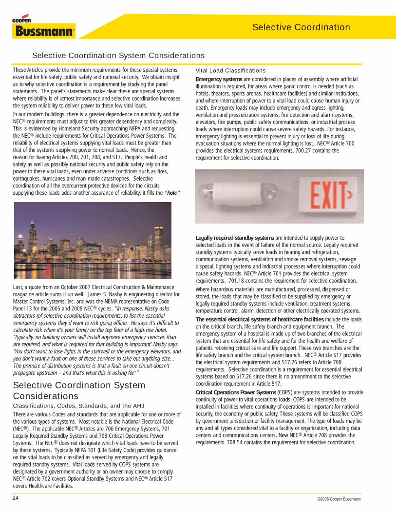
24 ©2008 Cooper Bussmann
Selective Coordination
These Articles provide the minimum requirements for these special systemsessential for life safety, public safety and national security. We obtain insightas to why selective coordination is a requirement by studying the panelstatements. The panel’s statements make clear these are special systemswhere reliability is of utmost importance and selective coordination increasesthe system reliability to deliver power to these few vital loads.In our modern buildings, there is a greater dependence on electricity and theNEC® requirements must adjust to this greater dependency and complexity.This is evidenced by Homeland Security approaching NFPA and requestingthe NEC® include requirements for Critical Operations Power Systems. Thereliability of electrical systems supplying vital loads must be greater thanthat of the systems supplying power to normal loads. Hence, the reason for having Articles 700, 701, 708, and 517. People’s health and safety as well as possibly national security and public safety rely on thepower to these vital loads, even under adverse conditions such as fires,earthquakes, hurricanes and man-made catastrophes. Selective coordination of all the overcurrent protective devices for the circuits supplying these loads adds another assurance of reliability: it fills the “hole”.
Last, a quote from an October 2007 Electrical Construction & Maintenancemagazine article sums it up well. James S. Nasby is engineering director forMaster Control Systems, Inc. and was the NEMA representative on CodePanel 13 for the 2005 and 2008 NEC® cycles. “In response, Nasby asksdetractors (of selective coordination requirements) to list the essential emergency systems they’d want to risk going offline. He says it’s difficult tocalculate risk when it’s your family on the top floor of a high-rise hotel.‘Typically, no building owners will install anymore emergency services thanare required, and what is required for that building is important’ Nasby says.‘You don’t want to lose lights in the stairwell or the emergency elevators, andyou don’t want a fault on one of these services to take out anything else...The premise of distribution systems is that a fault on one circuit doesn’tpropagate upstream – and that’s what this is asking for.’”
Selective Coordination SystemConsiderationsClassifications, Codes, Standards, and the AHJThere are various Codes and standards that are applicable for one or more ofthe various types of systems. Most notable is the National Electrical Code(NEC®). The applicable NEC® Articles are 700 Emergency Systems, 701Legally Required Standby Systems and 708 Critical Operations PowerSystems. The NEC® does not designate which vital loads have to be servedby these systems. Typically NFPA 101 (Life Safety Code) provides guidanceon the vital loads to be classified as served by emergency and legallyrequired standby systems. Vital loads served by COPS systems are designated by a government authority or an owner may choose to comply.NEC® Article 702 covers Optional Standby Systems and NEC® Article 517 covers Healthcare Facilities.
Vital Load ClassificationsEmergency systems are considered in places of assembly where artificialillumination is required, for areas where panic control is needed (such ashotels, theaters, sports arenas, healthcare facilities) and similar institutions,and where interruption of power to a vital load could cause human injury ordeath. Emergency loads may include emergency and egress lighting,ventilation and pressurization systems, fire detection and alarm systems,elevators, fire pumps, public safety communications, or industrial processloads where interruption could cause severe safety hazards. For instance,emergency lighting is essential to prevent injury or loss of life during evacuation situations where the normal lighting is lost. NEC® Article 700 provides the electrical systems requirements. 700.27 contains the requirement for selective coordination.
Legally required standby systems are intended to supply power to selected loads in the event of failure of the normal source. Legally requiredstandby systems typically serve loads in heating and refrigeration,communication systems, ventilation and smoke removal systems, sewagedisposal, lighting systems and industrial processes where interruption couldcause safety hazards. NEC® Article 701 provides the electrical system requirements. 701.18 contains the requirement for selective coordination.Where hazardous materials are manufactured, processed, dispensed orstored, the loads that may be classified to be supplied by emergency orlegally required standby systems include ventilation, treatment systems,temperature control, alarm, detection or other electrically operated systems.The essential electrical systems of healthcare facilities include the loadson the critical branch, life safety branch and equipment branch. The emergency system of a hospital is made up of two branches of the electricalsystem that are essential for life safety and for the health and welfare ofpatients receiving critical care and life support. These two branches are thelife safety branch and the critical system branch. NEC® Article 517 providesthe electrical system requirements and 517.26 refers to Article 700 requirements. Selective coordination is a requirement for essential electricalsystems based on 517.26 since there is no amendment to the selectivecoordination requirement in Article 517.Critical Operations Power Systems (COPS) are systems intended to providecontinuity of power to vital operations loads. COPS are intended to beinstalled in facilities where continuity of operations is important for nationalsecurity, the economy or public safety. These systems will be classified COPSby government jurisdiction or facility management. The type of loads may beany and all types considered vital to a facility or organization, including datacenters and communications centers. New NEC® Article 708 provides therequirements. 708.54 contains the requirement for selective coordination.
Selective Coordination System Considerations
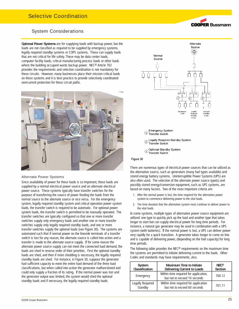
25©2008 Cooper Bussmann
Optional Power Systems are for supplying loads with backup power, but theloads are not classified as required to be supplied by emergency systems,legally required standby systems or COPS systems. These can supply loadsthat are not critical for life safety. These may be data center loads,computer facility loads, critical manufacturing process loads or other loadswhere the building occupant wants backup power. NEC® Article 702 provides the requirements and selective coordination is not mandatory forthese circuits. However, many businesses place their mission critical loadson these systems and it is best practice to provide selectively coordinated overcurrent protection for these circuit paths.
Alternate Power SystemsSince availability of power for these loads is so important, these loads aresupplied by a normal electrical power source and an alternate electricalpower source. These systems typically have transfer switches for the purpose of transferring the source of power feeding the loads from the normal source to the alternate source or vice versa. For the emergency system, legally required standby system and critical operation power systemloads, the transfer switch is required to be automatic. For optional powersystem loads, the transfer switch is permitted to be manually operated. Thetransfer switches are typically configured so that one or more transferswitches supply only emergency loads and another one or more transferswitches supply only legally required standby loads, and one or moretransfer switches supply the optional loads (see Figure 30). The systems are automated such that if normal power on the lineside terminals of a transferswitch is lost for any reason, the alternate source is called into action and atransfer is made to the alternate source supply. If for some reason the alternate power source supply can not meet the connected load demand, theloads are shed in reverse order of their priorities. First the optional standbyloads are shed, and then if more shedding is necessary, the legally requiredstandby loads are shed. For instance, in Figure 30, suppose the generatorhad sufficient capacity to meet the entire load demand of the three loadclassifications, but when called into action the generator malfunctioned andcould only supply a fraction of its rating. If the normal power was lost andthe generator output was limited, the system would shed the optional standby loads and if necessary, the legally required standby loads.
There are numerous types of electrical power sources that can be utilized asthe alternative source, such as generators (many fuel types available) andstored energy battery systems. Uninterruptible Power Systems (UPS) arealso often used. The selection of the alternate power source type(s) andpossibly stored energy/conversion equipment, such as UPS systems, arebased on many factors. Two of the most important criteria are:
1. After the normal power is lost, the time required for the alternative power system to commence delivering power to the vital loads.
2. The time duration that the alternative system must continue to deliver power tothe vital loads.
In some systems, multiple types of alternative power source equipment areutilized: one type to quickly pick up the load and another type that takeslonger to start but can supply electrical power for long time periods. Forinstance, a natural gas generator may be used in combination with a UPSsystem (with batteries). If the normal power is lost, a UPS can deliver powervery rapidly for a quick transition. A generator takes longer to come on lineand is capable of delivering power, (depending on the fuel capacity) for longtime periods.The following table provides the NEC® requirements on the maximum timethe systems are permitted to initiate delivering current to the loads. OtherCodes and standards may have requirements, also.
Figure 30
System Considerations
System Maximum Time to Initiate NEC®
Classification Delivering Current to Loads Section
Emergency Within time required for application, 700.12but not to exceed 10 secondsLegally Required Within time required for application 701.11Standby but not to exceed 60 seconds
Selective Coordination
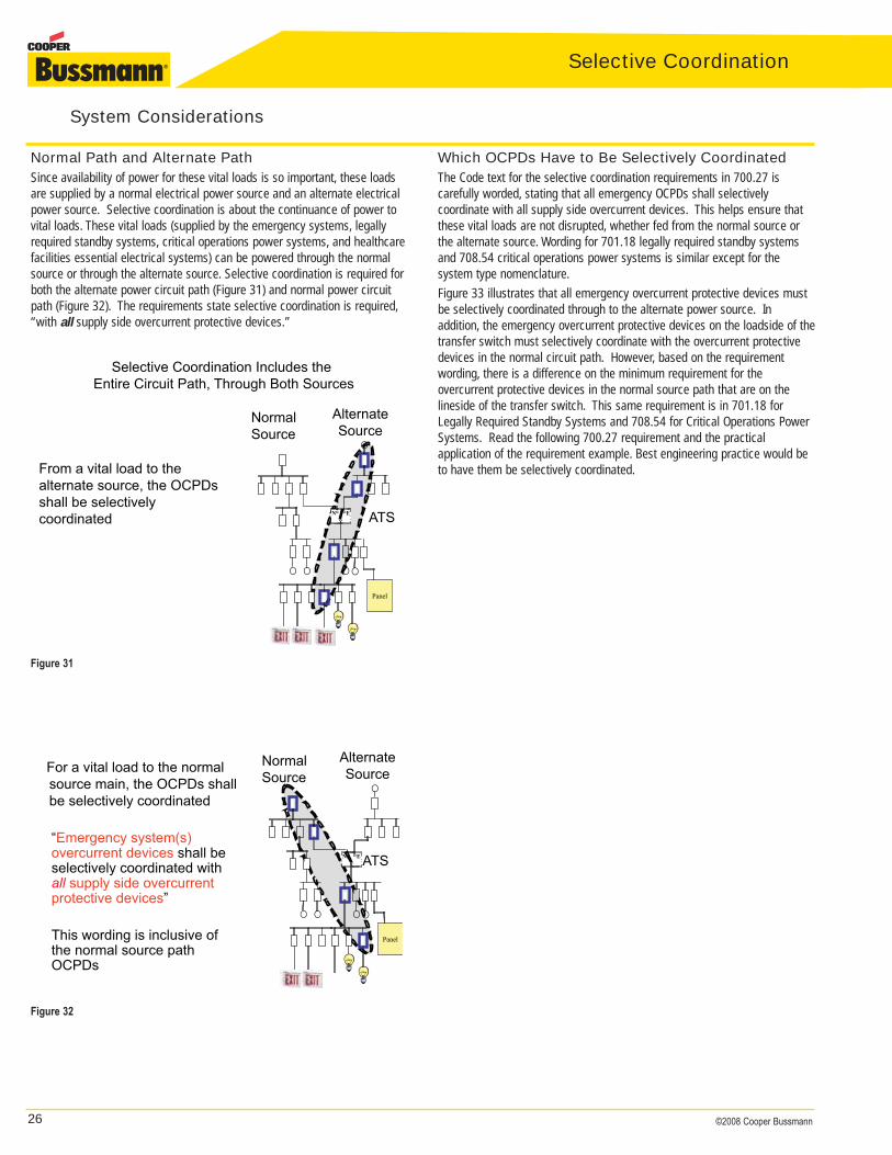
26 ©2008 Cooper Bussmann
Selective Coordination
Figure 31
Normal Path and Alternate PathSince availability of power for these vital loads is so important, these loadsare supplied by a normal electrical power source and an alternate electricalpower source. Selective coordination is about the continuance of power tovital loads. These vital loads (supplied by the emergency systems, legallyrequired standby systems, critical operations power systems, and healthcarefacilities essential electrical systems) can be powered through the normalsource or through the alternate source. Selective coordination is required forboth the alternate power circuit path (Figure 31) and normal power circuitpath (Figure 32). The requirements state selective coordination is required,“with all supply side overcurrent protective devices.”
Which OCPDs Have to Be Selectively CoordinatedThe Code text for the selective coordination requirements in 700.27 is carefully worded, stating that all emergency OCPDs shall selectively coordinate with all supply side overcurrent devices. This helps ensure thatthese vital loads are not disrupted, whether fed from the normal source orthe alternate source. Wording for 701.18 legally required standby systemsand 708.54 critical operations power systems is similar except for the system type nomenclature.Figure 33 illustrates that all emergency overcurrent protective devices mustbe selectively coordinated through to the alternate power source. In addition, the emergency overcurrent protective devices on the loadside of thetransfer switch must selectively coordinate with the overcurrent protectivedevices in the normal circuit path. However, based on the requirementwording, there is a difference on the minimum requirement for the overcurrent protective devices in the normal source path that are on the lineside of the transfer switch. This same requirement is in 701.18 forLegally Required Standby Systems and 708.54 for Critical Operations PowerSystems. Read the following 700.27 requirement and the practical application of the requirement example. Best engineering practice would beto have them be selectively coordinated.
Selective Coordination Includes theEntire Circuit Path, Through Both Sources
From a vital load to thealternate source, the OCPDsshall be selectivelycoordinated ATS
AlternateSource
N E
NormalSource
Panel
Figure 32
For a vital load to the normalsource main, the OCPDs shallbe selectively coordinated
ATS
AlternateSource
N E
NormalSource
Panel
“Emergency system(s)overcurrent devices shall beselectively coordinated withall supply side overcurrentprotective devices”
This wording is inclusive ofthe normal source pathOCPDs
System Considerations
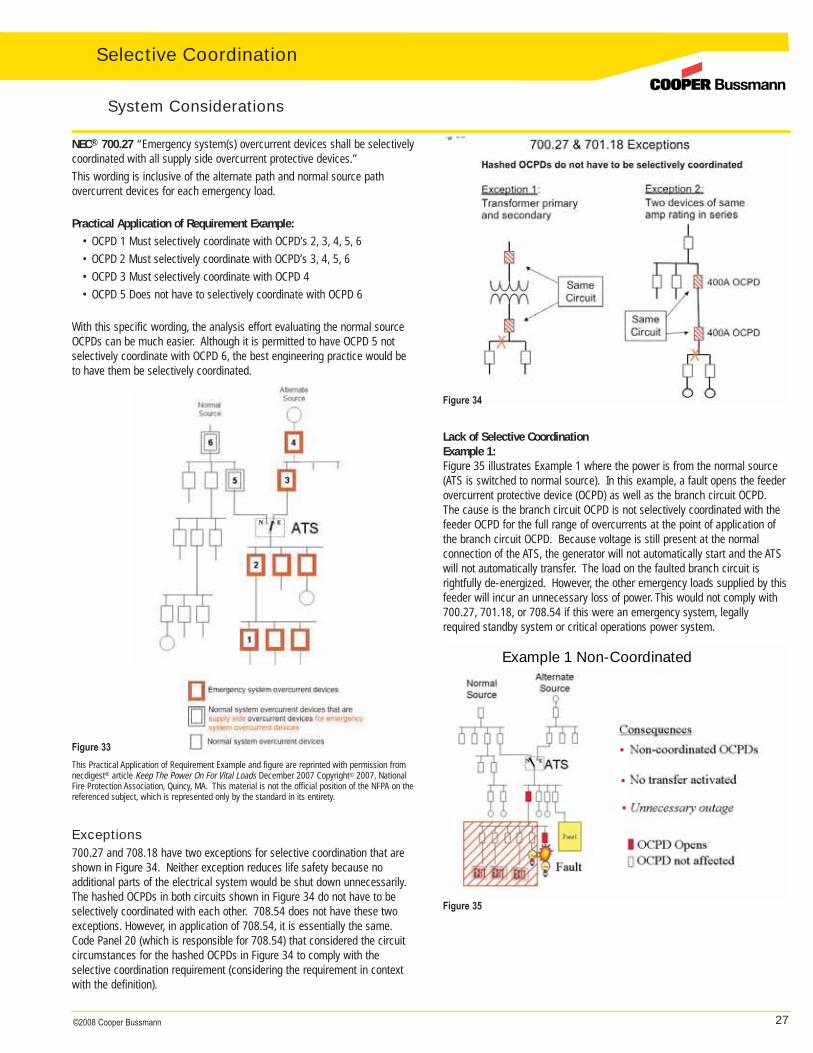
27©2008 Cooper Bussmann
Figure 33
Exceptions700.27 and 708.18 have two exceptions for selective coordination that areshown in Figure 34. Neither exception reduces life safety because no additional parts of the electrical system would be shut down unnecessarily.The hashed OCPDs in both circuits shown in Figure 34 do not have to beselectively coordinated with each other. 708.54 does not have these twoexceptions. However, in application of 708.54, it is essentially the same.Code Panel 20 (which is responsible for 708.54) that considered the circuit circumstances for the hashed OCPDs in Figure 34 to comply with the selective coordination requirement (considering the requirement in contextwith the definition).
This Practical Application of Requirement Example and figure are reprinted with permission fromnecdigest® article Keep The Power On For Vital Loads December 2007 Copyright© 2007, NationalFire Protection Association, Quincy, MA. This material is not the official position of the NFPA on thereferenced subject, which is represented only by the standard in its entirety.
Lack of Selective CoordinationExample 1:Figure 35 illustrates Example 1 where the power is from the normal source(ATS is switched to normal source). In this example, a fault opens the feeder overcurrent protective device (OCPD) as well as the branch circuit OCPD.The cause is the branch circuit OCPD is not selectively coordinated with thefeeder OCPD for the full range of overcurrents at the point of application ofthe branch circuit OCPD. Because voltage is still present at the normal connection of the ATS, the generator will not automatically start and the ATSwill not automatically transfer. The load on the faulted branch circuit is rightfully de-energized. However, the other emergency loads supplied by thisfeeder will incur an unnecessary loss of power. This would not comply with700.27, 701.18, or 708.54 if this were an emergency system, legallyrequired standby system or critical operations power system.
Figure 34
•
•
•
Example 1 Non-Coordinated
Figure 35
NEC® 700.27 “Emergency system(s) overcurrent devices shall be selectivelycoordinated with all supply side overcurrent protective devices.”This wording is inclusive of the alternate path and normal source path overcurrent devices for each emergency load.
Practical Application of Requirement Example:
• OCPD 1 Must selectively coordinate with OCPD’s 2, 3, 4, 5, 6• OCPD 2 Must selectively coordinate with OCPD’s 3, 4, 5, 6 • OCPD 3 Must selectively coordinate with OCPD 4• OCPD 5 Does not have to selectively coordinate with OCPD 6
With this specific wording, the analysis effort evaluating the normal sourceOCPDs can be much easier. Although it is permitted to have OCPD 5 notselectively coordinate with OCPD 6, the best engineering practice would beto have them be selectively coordinated.
System Considerations
Selective Coordination
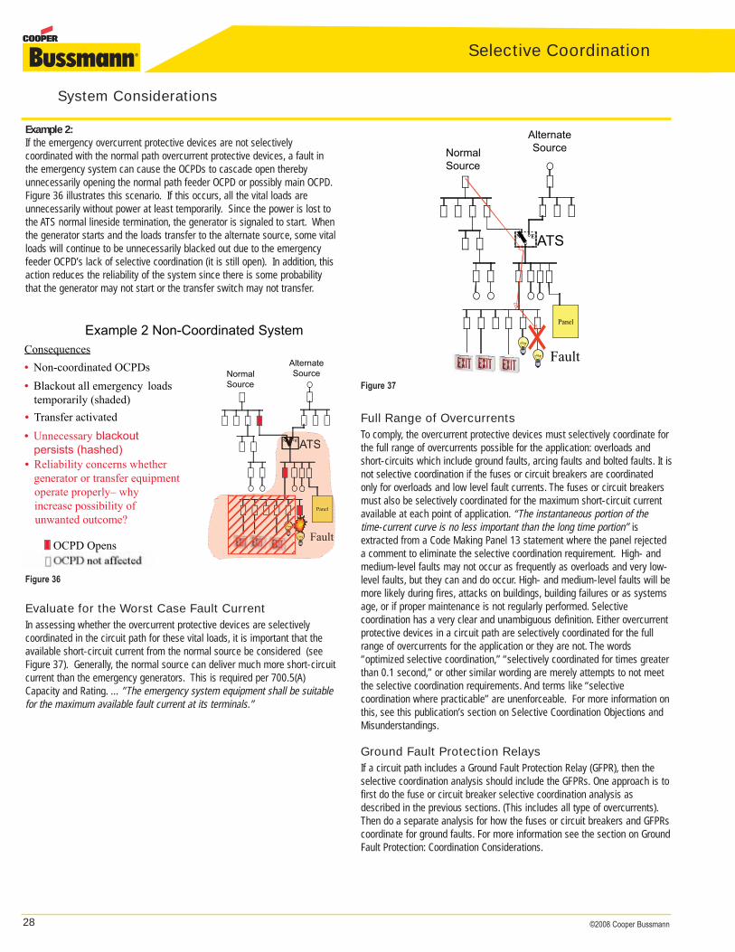
28 ©2008 Cooper Bussmann
Selective Coordination
Example 2:If the emergency overcurrent protective devices are not selectively coordinated with the normal path overcurrent protective devices, a fault inthe emergency system can cause the OCPDs to cascade open therebyunnecessarily opening the normal path feeder OCPD or possibly main OCPD.Figure 36 illustrates this scenario. If this occurs, all the vital loads areunnecessarily without power at least temporarily. Since the power is lost tothe ATS normal lineside termination, the generator is signaled to start. Whenthe generator starts and the loads transfer to the alternate source, some vitalloads will continue to be unnecessarily blacked out due to the emergencyfeeder OCPD’s lack of selective coordination (it is still open). In addition, thisaction reduces the reliability of the system since there is some probabilitythat the generator may not start or the transfer switch may not transfer.
ATS
AlternateSource
N E
NormalSource
Example 2 Non-Coordinated SystemConsequences
• Non-coordinated OCPDs
OCPD Opens
Panel
Fault
• Reliability concerns whethergenerator or transfer equipmentoperate properly – whyincrease possibility ofunwanted outcome?
• Unnecessary blackout persists (hashed)
• Transfer activated
ATSNN E
Panel
Fault
• Blackout all emergency loadstemporarily (shaded)
Figure 36
ATS
AlternateSource
N E
NormalSource
Panel
Fault
Figure 37
Evaluate for the Worst Case Fault CurrentIn assessing whether the overcurrent protective devices are selectively coordinated in the circuit path for these vital loads, it is important that theavailable short-circuit current from the normal source be considered (seeFigure 37). Generally, the normal source can deliver much more short-circuitcurrent than the emergency generators. This is required per 700.5(A)Capacity and Rating. …”The emergency system equipment shall be suitablefor the maximum available fault current at its terminals.”
Full Range of OvercurrentsTo comply, the overcurrent protective devices must selectively coordinate forthe full range of overcurrents possible for the application: overloads andshort-circuits which include ground faults, arcing faults and bolted faults. It isnot selective coordination if the fuses or circuit breakers are coordinatedonly for overloads and low level fault currents. The fuses or circuit breakersmust also be selectively coordinated for the maximum short-circuit currentavailable at each point of application. “The instantaneous portion of the time-current curve is no less important than the long time portion” isextracted from a Code Making Panel 13 statement where the panel rejecteda comment to eliminate the selective coordination requirement. High- andmedium-level faults may not occur as frequently as overloads and very low-level faults, but they can and do occur. High- and medium-level faults will bemore likely during fires, attacks on buildings, building failures or as systemsage, or if proper maintenance is not regularly performed. Selective coordination has a very clear and unambiguous definition. Either overcurrentprotective devices in a circuit path are selectively coordinated for the fullrange of overcurrents for the application or they are not. The words “optimized selective coordination,” “selectively coordinated for times greaterthan 0.1 second,” or other similar wording are merely attempts to not meetthe selective coordination requirements. And terms like “selective coordination where practicable” are unenforceable. For more information onthis, see this publication’s section on Selective Coordination Objections andMisunderstandings.
Ground Fault Protection RelaysIf a circuit path includes a Ground Fault Protection Relay (GFPR), then theselective coordination analysis should include the GFPRs. One approach is tofirst do the fuse or circuit breaker selective coordination analysis asdescribed in the previous sections. (This includes all type of overcurrents).Then do a separate analysis for how the fuses or circuit breakers and GFPRscoordinate for ground faults. For more information see the section on GroundFault Protection: Coordination Considerations.
System Considerations
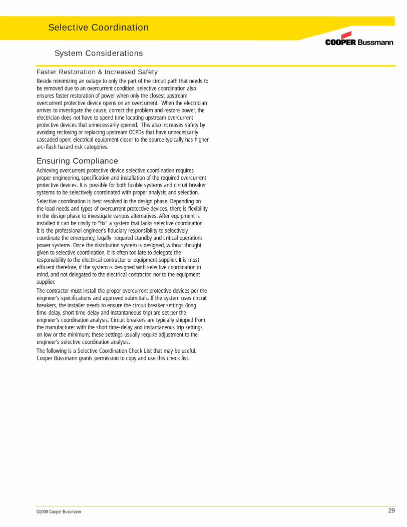
29©2008 Cooper Bussmann
Faster Restoration & Increased SafetyBeside minimizing an outage to only the part of the circuit path that needs tobe removed due to an overcurrent condition, selective coordination alsoensures faster restoration of power when only the closest upstream overcurrent protective device opens on an overcurrent. When the electricianarrives to investigate the cause, correct the problem and restore power, theelectrician does not have to spend time locating upstream overcurrent protective devices that unnecessarily opened. This also increases safety byavoiding reclosing or replacing upstream OCPDs that have unnecessarilycascaded open; electrical equipment closer to the source typically has higherarc-flash hazard risk categories.
Ensuring ComplianceAchieving overcurrent protective device selective coordination requires proper engineering, specification and installation of the required overcurrentprotective devices. It is possible for both fusible systems and circuit breakersystems to be selectively coordinated with proper analysis and selection.Selective coordination is best resolved in the design phase. Depending onthe load needs and types of overcurrent protective devices, there is flexibilityin the design phase to investigate various alternatives. After equipment isinstalled it can be costly to “fix” a system that lacks selective coordination.It is the professional engineer’s fiduciary responsibility to selectively coordinate the emergency, legally required standby and critical operationspower systems. Once the distribution system is designed, without thoughtgiven to selective coordination, it is often too late to delegate the responsibility to the electrical contractor or equipment supplier. It is mostefficient therefore, if the system is designed with selective coordination inmind, and not delegated to the electrical contractor, nor to the equipmentsupplier.The contractor must install the proper overcurrent protective devices per theengineer’s specifications and approved submittals. If the system uses circuitbreakers, the installer needs to ensure the circuit breaker settings (longtime-delay, short time-delay and instantaneous trip) are set per the engineer’s coordination analysis. Circuit breakers are typically shipped fromthe manufacturer with the short time-delay and instantaneous trip settingson low or the minimum; these settings usually require adjustment to the engineer’s selective coordination analysis.The following is a Selective Coordination Check List that may be useful.Cooper Bussmann grants permission to copy and use this check list.
System Considerations
Selective Coordination
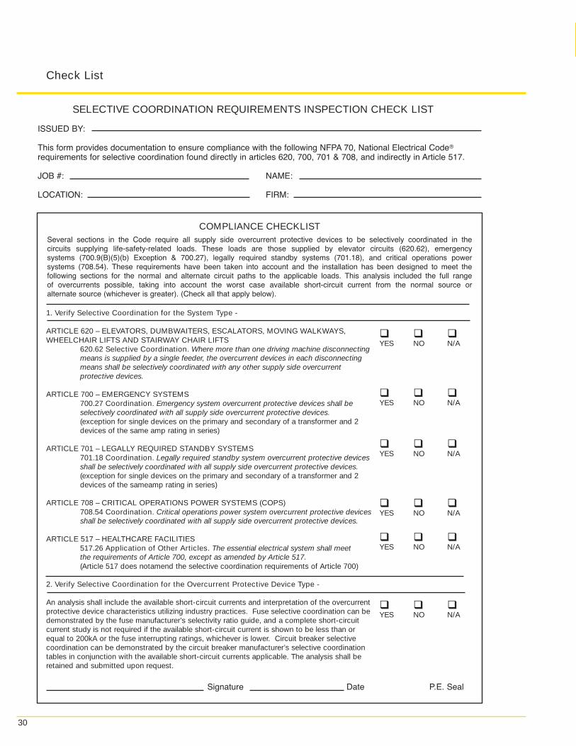
30
Check List
Several sections in the Code require all supply side overcurrent protective devices to be selectively coordinated in thecircuits supplying life-safety-related loads. These loads are those supplied by elevator circuits (620.62), emergencysystems (700.9(B)(5)(b) Exception & 700.27), legally required standby systems (701.18), and critical operations powersystems (708.54). These requirements have been taken into account and the installation has been designed to meet thefollowing sections for the normal and alternate circuit paths to the applicable loads. This analysis included the full rangeof overcurrents possible, taking into account the worst case available short-circuit current from the normal source oralternate source (whichever is greater). (Check all that apply below).
SELECTIVE COORDINATION REQUIREMENTS INSPECTION CHECK LIST
ISSUED BY:
This form provides documentation to ensure compliance with the following NFPA 70, National Electrical Code®
requirements for selective coordination found directly in articles 620, 700, 701 & 708, and indirectly in Article 517.
JOB #: NAME:
LOCATION: FIRM:
COMPLIANCE CHECKLIST
1. Verify Selective Coordination for the System Type -
ARTICLE 620 – ELEVATORS, DUMBWAITERS, ESCALATORS, MOVING WALKWAYS,WHEELCHAIR LIFTS AND STAIRWAY CHAIR LIFTS
620.62 Selective Coordination. Where more than one driving machine disconnectingmeans is supplied by a single feeder, the overcurrent devices in each disconnectingmeans shall be selectively coordinated with any other supply side overcurrentprotective devices.
ARTICLE 700 – EMERGENCY SYSTEMS700.27 Coordination. Emergency system overcurrent protective devices shall beselectively coordinated with all supply side overcurrent protective devices.(exception for single devices on the primary and secondary of a transformer and 2 devices of the same amp rating in series)
ARTICLE 701 – LEGALLY REQUIRED STANDBY SYSTEMS701.18 Coordination. Legally required standby system overcurrent protective devicesshall be selectively coordinated with all supply side overcurrent protective devices.(exception for single devices on the primary and secondary of a transformer and 2 devices of the sameamp rating in series)
ARTICLE 708 – CRITICAL OPERATIONS POWER SYSTEMS (COPS)708.54 Coordination. Critical operations power system overcurrent protective devicesshall be selectively coordinated with all supply side overcurrent protective devices.
ARTICLE 517 – HEALTHCARE FACILITIES517.26 Application of Other Articles. The essential electrical system shall meetthe requirements of Article 700, except as amended by Article 517.(Article 517 does notamend the selective coordination requirements of Article 700)
2. Verify Selective Coordination for the Overcurrent Protective Device Type -
An analysis shall include the available short-circuit currents and interpretation of the overcurrent protective device characteristics utilizing industry practices. Fuse selective coordination can be demonstrated by the fuse manufacturer’s selectivity ratio guide, and a complete short-circuit current study is not required if the available short-circuit current is shown to be less than or equal to 200kA or the fuse interrupting ratings, whichever is lower. Circuit breaker selective coordination can be demonstrated by the circuit breaker manufacturer’s selective coordination tables in conjunction with the available short-circuit currents applicable. The analysis shall be retained and submitted upon request.
� � �YES NO N/A
� � �YES NO N/A
� � �YES NO N/A
� � �YES NO N/A
� � �YES NO N/A
� � �YES NO N/A
Signature Date P.E. Seal
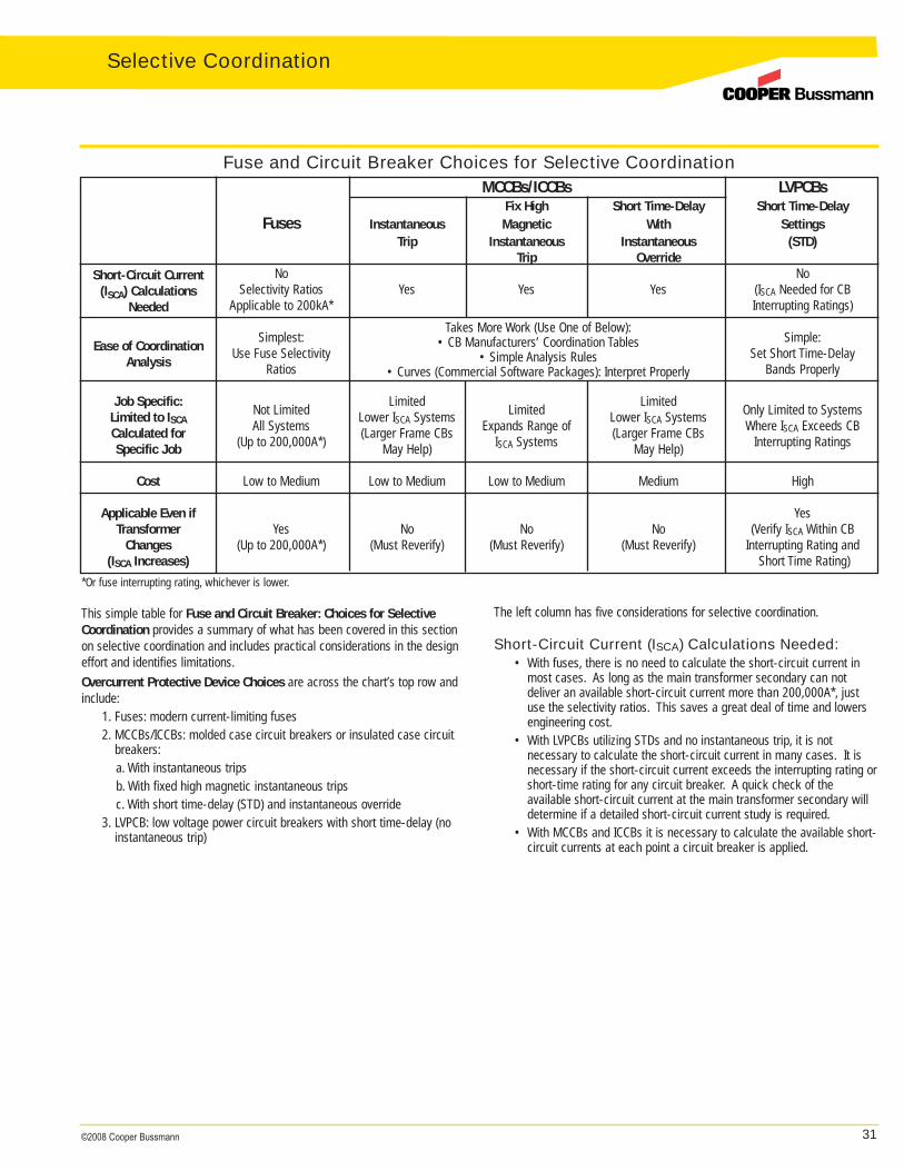
31©2008 Cooper Bussmann
MCCBs/ICCBs LVPCBsFix High Short Time-Delay Short Time-Delay
Fuses Instantaneous Magnetic With SettingsTrip Instantaneous Instantaneous (STD)
Trip OverrideShort-Circuit Current No No
(ISCA) Calculations Selectivity Ratios Yes Yes Yes (ISCA Needed for CBNeeded Applicable to 200kA* Interrupting Ratings)
Simplest: Simple:Ease of Coordination Use Fuse Selectivity Set Short Time-Delay
Analysis Ratios Bands Properly
Job Specific: Limited LimitedLimited to ISCA
Not Limited Lower ISCA Systems Limited Lower ISCA Systems Only Limited to Systems
Calculated for All Systems (Larger Frame CBs Expands Range of (Larger Frame CBs Where ISCA Exceeds CB
Specific Job (Up to 200,000A*) May Help) ISCA Systems May Help) Interrupting Ratings
Cost Low to Medium Low to Medium Low to Medium Medium High
Applicable Even if YesTransformer Yes No No No (Verify ISCA Within CB
Changes (Up to 200,000A*) (Must Reverify) (Must Reverify) (Must Reverify) Interrupting Rating and(ISCA Increases) Short Time Rating)
Fuse and Circuit Breaker Choices for Selective Coordination
The left column has five considerations for selective coordination.
Short-Circuit Current (ISCA) Calculations Needed:• With fuses, there is no need to calculate the short-circuit current in
most cases. As long as the main transformer secondary can notdeliver an available short-circuit current more than 200,000A*, justuse the selectivity ratios. This saves a great deal of time and lowers engineering cost.
• With LVPCBs utilizing STDs and no instantaneous trip, it is not necessary to calculate the short-circuit current in many cases. It isnecessary if the short-circuit current exceeds the interrupting rating orshort-time rating for any circuit breaker. A quick check of the available short-circuit current at the main transformer secondary willdetermine if a detailed short-circuit current study is required.
• With MCCBs and ICCBs it is necessary to calculate the available short-circuit currents at each point a circuit breaker is applied.
This simple table for Fuse and Circuit Breaker: Choices for SelectiveCoordination provides a summary of what has been covered in this sectionon selective coordination and includes practical considerations in the designeffort and identifies limitations.Overcurrent Protective Device Choices are across the chart’s top row andinclude:
1. Fuses: modern current-limiting fuses2. MCCBs/ICCBs: molded case circuit breakers or insulated case circuit
breakers:a. With instantaneous tripsb. With fixed high magnetic instantaneous tripsc. With short time-delay (STD) and instantaneous override
3. LVPCB: low voltage power circuit breakers with short time-delay (noinstantaneous trip)
Takes More Work (Use One of Below):• CB Manufacturers’ Coordination Tables
• Simple Analysis Rules• Curves (Commercial Software Packages): Interpret Properly
*Or fuse interrupting rating, whichever is lower.
Selective Coordination
32 ©2008 Cooper Bussmann
Selective Coordination
Ease of Coordination Analysis:• With fuses, just use the selectivity ratio guide which is applicable for
the full range of overcurrents up to the fuses’ interrupting ratings or200,000A, which is lower. This saves a great deal of time and lowersthe engineering cost.
• With LVPCBs, utilizing STDs and no instantaneous trip, it is a matter ofselecting short time-delay bands that do not intersect. However, it iseasy to achieve selective coordination.
• With MCCBs and ICCBs it is necessary to do a detailed analysis. Thisis because the available short-circuit currents may trip the upstreamcircuit breakers. The method entails knowing the available short-circuit current at each CB point of application and determining ifthe circuit breakers are selectively coordinated or not. Three methods are:
1. Circuit breaker coordination tables (published by each CB manufacturer).
2. Analysis method (without plotting curves) presented in a previous section.
3. Using a commercial software package that plots the curves (necessary to interpret the curves properly).
Job Specific: Limited to ISCA Calculated for Specific Job
• With fuses, the selective coordination scheme determined is not limited just to that specific job since it is a matter of utilizing theselectivity ratios. The same specification of fuse types and sizescould be utilized for another project as long as the short-circuit current is not greater than 200,000A*.
• With LVPCBs, utilizing STDs and no instantaneous trip, the selectivecoordination scheme determined is not limited just to that specific jobsince it is a matter of specifying STD bands that do not intersect.Once determined, the same specification of circuit breaker types and settings could be used on another project, as long as the short-circuitcurrent does not exceed any circuit breaker interrupting or short time-delay rating.
• With MCCBs and ICCBs the selective coordination scheme that isselectively coordinated for one project is not necessarily transferableto another project. The reason is that even if the same circuit breakers are used, each project will have its own specific availableshort-circuit currents. Therefore, using these type circuit breakersrequires each project to have a short-circuit current and coordinationanalysis.
Cost:• This row is a rough estimate of the cost range of the electrical
equipment.
Applicable Even if Transformer Changes (ISCA increases):
• With fuses, even if there is a system change that increases theshort-circuit current, such as when the main transformer getschanged, selective coordination is retained (up to 200,000A*).
• With LVPCBs, utilizing STDs and no instantaneous trip, the selectivecoordination is also retained. In this case, it is necessary to verify thehigher short-circuit current does not now exceed the interrupting orshort time-delay rating for any circuit breaker.
• With MCCBs and ICCBs selective coordination may be negated if theshort-circuit current increases due to a system change. It is necessary to perform a new short-circuit current study and revisit theselective coordination analysis to verify if selective coordination is still valid.
Note: If the system includes ground fault protection relays, selective coordination must be analyzed with these protective devices, also. See thesection on Selective Coordination: Ground Fault Protection Relays.
*Or fuse interrupting rating, whichever is lower.

33©2008 Cooper Bussmann
Objection 1
Changing the requirement for selective coordination to times of 0.1 secondand greater is a better method.Clarifying Facts to Objection 1
A. The Code Making Panels have already considered this option and rejected it. The real question that has already been answered by the industry experts on three National Electrical Code panels is what level of coordination is required to provide system reliability to supply power to vital loads. Their answer is selective coordination, for the full range of overcurrents. Selective coordination can not be specified by time parameters as some are promoting. Selective coordination is a matter of the available fault current and how characteristics of the various overcurrent protective devices in series in the circuit path perform relative to one another. Selective coordination is for the full range of overcurrents that the specific system is capable of delivering. In reality it comes down to this:• Fuses: if the fuses comply with the fuse manufacturer’s selectivity
ratios, the fuses selectively coordinate for fault currents up to 200,000A or the fuses interrupting rating, whichever is lower. There is no need to limit reliability to times of only 0.1 second and longer.
• Circuit breakers: the fault current level in the specific system/location determines the type of circuit breakers that would be the most cost effective and still selectively coordinate. If there are low available fault currents, then molded case circuit breakers may comply. If the fault current is in a higher range, then molded case circuit breakers with fixed high magnetic instantaneous trips may comply. If not, then short time-delay circuit breakers may be necessary. See the section on Achieving Selective Coordination with Low Voltage Circuit Breakersfor more details on the various options for different levels of fault current. As with fusible systems, circuit breaker solutions are available to provide selective coordination for all available fault currents.
B. The argument to consider coordination for times only greater than 0.1 second is merely a tactic to circumvent the detailed engineering required to ensure a more reliable system for life safety. It is only half of the story. It clearly is intended to ignore circuit breaker instantaneous trip settings when analyzing selective coordination. This will provide coordination for primarily only overloads and it will not even ensure selective coordination for low level arcing fault currents on many systems. This is purely a ploy by some individuals who do not want to alter their typical “cookie cutter” designs to meet the new higher reliability requirements. If all levels of short-circuit currents are not an important criteria, why be concerned with complying with the interrupting rating requirements of NEC® 110.9 or short-circuit current rating requirements such as 110.10? Code panel 13 recognized that selective coordination has to be for the full range of overcurrents. In a panel statement rejecting a proposal to modify the selective coordination requirement, included “The instantaneous portion of the time-current curve is no less important than the long time portion.”(The instantaneous portion covers times below 0.1 second) (Panel Statement to Comment 13-135 during the 2005 NEC® cycle.)
C. Overcurrents in branch circuits can be either overloads or faults.However, overcurrents in feeder circuits (distribution panels and switchboards) tend to be faults and not overloads. As a consequence,without selective coordination for the full range of overcurrents, feeder faults will have a greater probability to unnecessarily blackout vital life safety loads due to cascading overcurrent protective devices.
Selective Coordination Objections & Misunderstandings
Selective Coordination Objections andMisunderstandingsMandatory selective coordination required in the NEC® for the circuit pathsof some vital loads requires some changes in the industry. As with anychange, there are those who are quick adopters and they have moved on,ensuring their design, installations and inspections comply. Others havebeen more reluctant to change. Although selective coordination is an easyconcept to understand, the devil can be in the details. This section presentsthe most common objections voiced in opposition to the selective coordination requirements with accompanying clarifying facts. As with anycomplex subject, it is easy to provide general statements that support oroppose a position. As one digs deeper into the objections, the realitybecomes:
1. For many of the objections, there are remedies or technologies that are suitable solutions
2. Some of the objections are not accurate 3. For other objections, since selective coordination is now mandatory,
selective coordination is a higher priority All these arguments as to why mandatory selective coordination requirements should be deleted or diluted have been thoroughly presented,discussed and debated in the technical Code panels as well as in otherindustry forums for more than two Code cycles. For elevator circuits,selective coordination has been a mandatory requirement since the 1993NEC®. Three Code panels have made selective coordination a mandatoryrequirement because it increases the system reliability for powering vital lifesafety loads and it is achievable with existing technology. In addition, as istypical with significant industry changes, manufacturers are responding withnew products that make it easier and less costly to comply.To answer the broad question why selective coordination is needed as aNEC® requirement, see the section on: Why Selective Coordination isMandatory: It fills the reliability “Hole.”
Selective Coordination
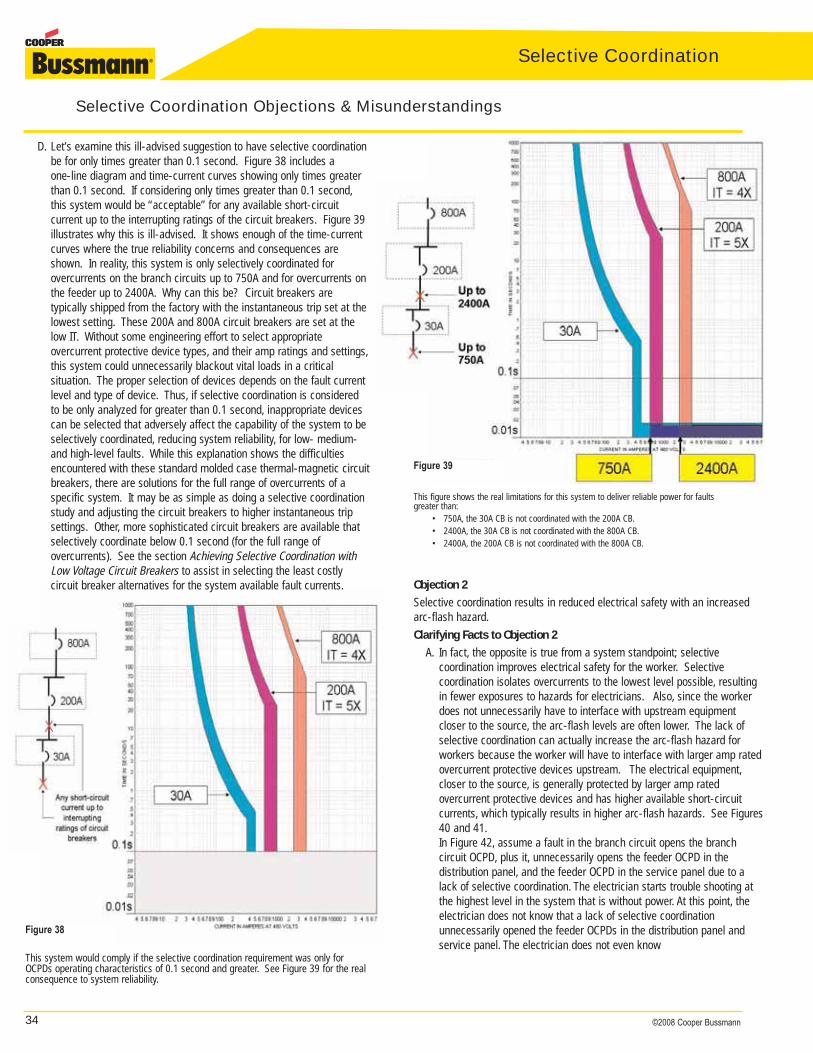
34 ©2008 Cooper Bussmann
Selective Coordination
Figure 38
D. Let’s examine this ill-advised suggestion to have selective coordination be for only times greater than 0.1 second. Figure 38 includes a one-line diagram and time-current curves showing only times greater than 0.1 second. If considering only times greater than 0.1 second,this system would be “acceptable” for any available short-circuit current up to the interrupting ratings of the circuit breakers. Figure 39 illustrates why this is ill-advised. It shows enough of the time-current curves where the true reliability concerns and consequences are shown. In reality, this system is only selectively coordinated for overcurrents on the branch circuits up to 750A and for overcurrents on the feeder up to 2400A. Why can this be? Circuit breakers are typically shipped from the factory with the instantaneous trip set at the lowest setting. These 200A and 800A circuit breakers are set at the low IT. Without some engineering effort to select appropriate overcurrent protective device types, and their amp ratings and settings,this system could unnecessarily blackout vital loads in a critical situation. The proper selection of devices depends on the fault current level and type of device. Thus, if selective coordination is considered to be only analyzed for greater than 0.1 second, inappropriate devices can be selected that adversely affect the capability of the system to be selectively coordinated, reducing system reliability, for low- medium- and high-level faults. While this explanation shows the difficulties encountered with these standard molded case thermal-magnetic circuit breakers, there are solutions for the full range of overcurrents of a specific system. It may be as simple as doing a selective coordination study and adjusting the circuit breakers to higher instantaneous trip settings. Other, more sophisticated circuit breakers are available that selectively coordinate below 0.1 second (for the full range of overcurrents). See the section Achieving Selective Coordination with Low Voltage Circuit Breakers to assist in selecting the least costly circuit breaker alternatives for the system available fault currents.
Figure 39
Selective Coordination Objections & Misunderstandings
This system would comply if the selective coordination requirement was only forOCPDs operating characteristics of 0.1 second and greater. See Figure 39 for the realconsequence to system reliability.
Objection 2
Selective coordination results in reduced electrical safety with an increasedarc-flash hazard.Clarifying Facts to Objection 2
A. In fact, the opposite is true from a system standpoint; selective coordination improves electrical safety for the worker. Selective coordination isolates overcurrents to the lowest level possible, resulting in fewer exposures to hazards for electricians. Also, since the worker does not unnecessarily have to interface with upstream equipment closer to the source, the arc-flash levels are often lower. The lack of selective coordination can actually increase the arc-flash hazard for workers because the worker will have to interface with larger amp rated overcurrent protective devices upstream. The electrical equipment,closer to the source, is generally protected by larger amp rated overcurrent protective devices and has higher available short-circuit currents, which typically results in higher arc-flash hazards. See Figures 40 and 41.In Figure 42, assume a fault in the branch circuit opens the branch circuit OCPD, plus it, unnecessarily opens the feeder OCPD in the distribution panel, and the feeder OCPD in the service panel due to a lack of selective coordination. The electrician starts trouble shooting at the highest level in the system that is without power. At this point, the electrician does not know that a lack of selective coordination unnecessarily opened the feeder OCPDs in the distribution panel and service panel. The electrician does not even know
This figure shows the real limitations for this system to deliver reliable power for faultsgreater than:
• 750A, the 30A CB is not coordinated with the 200A CB.• 2400A, the 30A CB is not coordinated with the 800A CB.• 2400A, the 200A CB is not coordinated with the 800A CB.
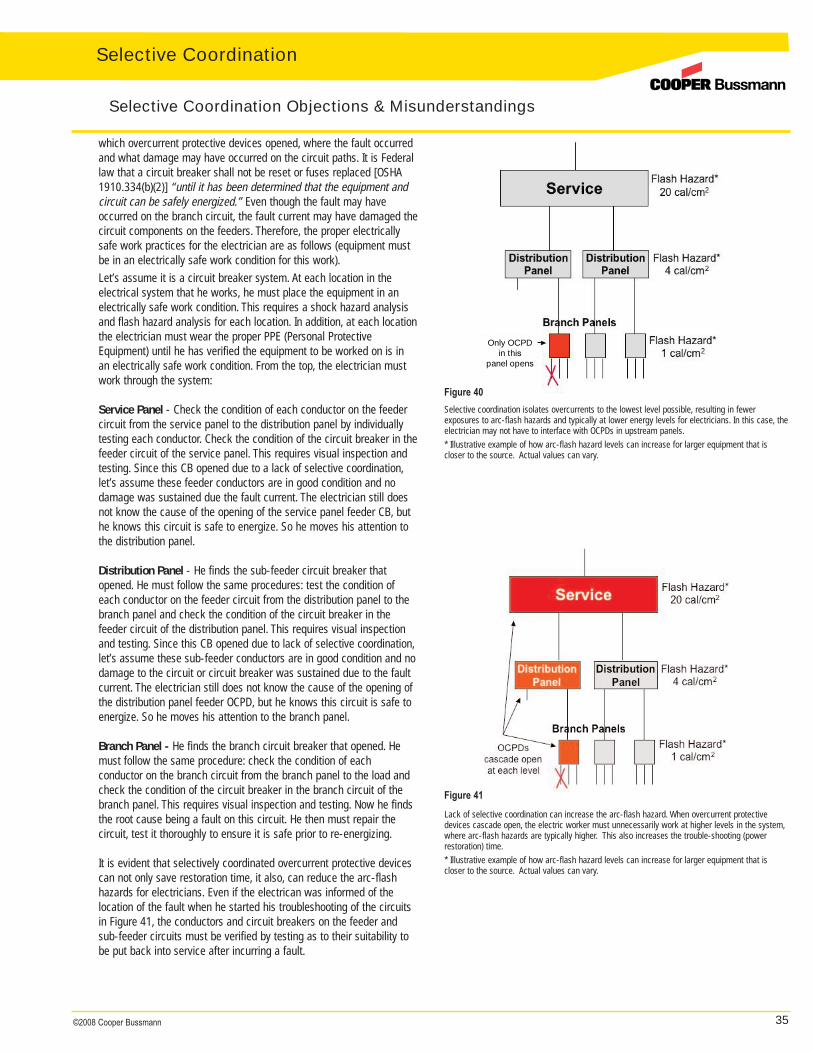
35©2008 Cooper Bussmann
Only OCPDin this
panel opens
Figure 40
Figure 41
Selective coordination isolates overcurrents to the lowest level possible, resulting in fewer exposures to arc-flash hazards and typically at lower energy levels for electricians. In this case, the electrician may not have to interface with OCPDs in upstream panels.* Illustrative example of how arc-flash hazard levels can increase for larger equipment that is closer to the source. Actual values can vary.
Lack of selective coordination can increase the arc-flash hazard. When overcurrent protectivedevices cascade open, the electric worker must unnecessarily work at higher levels in the system,where arc-flash hazards are typically higher. This also increases the trouble-shooting (power restoration) time.* Illustrative example of how arc-flash hazard levels can increase for larger equipment that is closer to the source. Actual values can vary.
Selective Coordination Objections & Misunderstandings
which overcurrent protective devices opened, where the fault occurred and what damage may have occurred on the circuit paths. It is Federal law that a circuit breaker shall not be reset or fuses replaced [OSHA 1910.334(b)(2)] “until it has been determined that the equipment and circuit can be safely energized.” Even though the fault may have occurred on the branch circuit, the fault current may have damaged thecircuit components on the feeders. Therefore, the proper electrically safe work practices for the electrician are as follows (equipment must be in an electrically safe work condition for this work).Let’s assume it is a circuit breaker system. At each location in the electrical system that he works, he must place the equipment in an electrically safe work condition. This requires a shock hazard analysis and flash hazard analysis for each location. In addition, at each location the electrician must wear the proper PPE (Personal Protective Equipment) until he has verified the equipment to be worked on is in an electrically safe work condition. From the top, the electrician must work through the system:
Service Panel - Check the condition of each conductor on the feeder circuit from the service panel to the distribution panel by individually testing each conductor. Check the condition of the circuit breaker in thefeeder circuit of the service panel. This requires visual inspection and testing. Since this CB opened due to a lack of selective coordination,let’s assume these feeder conductors are in good condition and no damage was sustained due the fault current. The electrician still does not know the cause of the opening of the service panel feeder CB, but he knows this circuit is safe to energize. So he moves his attention to the distribution panel.
Distribution Panel - He finds the sub-feeder circuit breaker that opened. He must follow the same procedures: test the condition of each conductor on the feeder circuit from the distribution panel to the branch panel and check the condition of the circuit breaker in the feeder circuit of the distribution panel. This requires visual inspection and testing. Since this CB opened due to lack of selective coordination,let’s assume these sub-feeder conductors are in good condition and no damage to the circuit or circuit breaker was sustained due to the fault current. The electrician still does not know the cause of the opening of the distribution panel feeder OCPD, but he knows this circuit is safe to energize. So he moves his attention to the branch panel.
Branch Panel - He finds the branch circuit breaker that opened. He must follow the same procedure: check the condition of each conductor on the branch circuit from the branch panel to the load and check the condition of the circuit breaker in the branch circuit of the branch panel. This requires visual inspection and testing. Now he finds the root cause being a fault on this circuit. He then must repair the circuit, test it thoroughly to ensure it is safe prior to re-energizing.
It is evident that selectively coordinated overcurrent protective devices can not only save restoration time, it also, can reduce the arc-flash hazards for electricians. Even if the electrican was informed of the location of the fault when he started his troubleshooting of the circuits in Figure 41, the conductors and circuit breakers on the feeder and sub-feeder circuits must be verified by testing as to their suitability to be put back into service after incurring a fault.
Selective Coordination
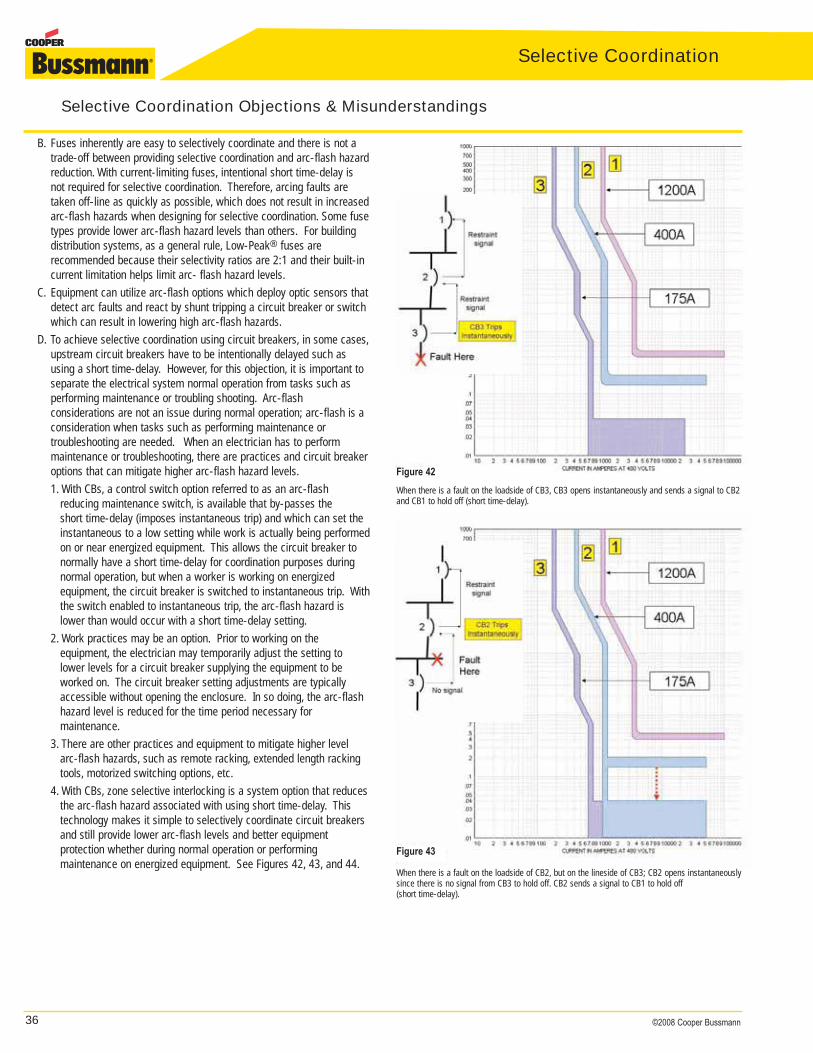
36 ©2008 Cooper Bussmann
Selective Coordination
B. Fuses inherently are easy to selectively coordinate and there is not a trade-off between providing selective coordination and arc-flash hazard reduction. With current-limiting fuses, intentional short time-delay is not required for selective coordination. Therefore, arcing faults are taken off-line as quickly as possible, which does not result in increased arc-flash hazards when designing for selective coordination. Some fuse types provide lower arc-flash hazard levels than others. For building distribution systems, as a general rule, Low-Peak® fuses are recommended because their selectivity ratios are 2:1 and their built-in current limitation helps limit arc- flash hazard levels.
C. Equipment can utilize arc-flash options which deploy optic sensors thatdetect arc faults and react by shunt tripping a circuit breaker or switch which can result in lowering high arc-flash hazards.
D. To achieve selective coordination using circuit breakers, in some cases,upstream circuit breakers have to be intentionally delayed such as using a short time-delay. However, for this objection, it is important to separate the electrical system normal operation from tasks such as performing maintenance or troubling shooting. Arc-flash considerations are not an issue during normal operation; arc-flash is a consideration when tasks such as performing maintenance or troubleshooting are needed. When an electrician has to perform maintenance or troubleshooting, there are practices and circuit breaker options that can mitigate higher arc-flash hazard levels.1. With CBs, a control switch option referred to as an arc-flash
reducing maintenance switch, is available that by-passes the short time-delay (imposes instantaneous trip) and which can set the instantaneous to a low setting while work is actually being performed on or near energized equipment. This allows the circuit breaker to normally have a short time-delay for coordination purposes during normal operation, but when a worker is working on energized equipment, the circuit breaker is switched to instantaneous trip. With the switch enabled to instantaneous trip, the arc-flash hazard is lower than would occur with a short time-delay setting.
2. Work practices may be an option. Prior to working on the equipment, the electrician may temporarily adjust the setting to lower levels for a circuit breaker supplying the equipment to be worked on. The circuit breaker setting adjustments are typically accessible without opening the enclosure. In so doing, the arc-flash hazard level is reduced for the time period necessary for maintenance.
3. There are other practices and equipment to mitigate higher level arc-flash hazards, such as remote racking, extended length racking tools, motorized switching options, etc.
4. With CBs, zone selective interlocking is a system option that reduces the arc-flash hazard associated with using short time-delay. This technology makes it simple to selectively coordinate circuit breakers and still provide lower arc-flash levels and better equipment protection whether during normal operation or performing maintenance on energized equipment. See Figures 42, 43, and 44.
Figure 42
Figure 43
When there is a fault on the loadside of CB3, CB3 opens instantaneously and sends a signal to CB2and CB1 to hold off (short time-delay).
When there is a fault on the loadside of CB2, but on the lineside of CB3; CB2 opens instantaneouslysince there is no signal from CB3 to hold off. CB2 sends a signal to CB1 to hold off (short time-delay).
Selective Coordination Objections & Misunderstandings

37©2008 Cooper Bussmann
Objection 4
Selective coordination results in greater equipment short-circuit damagewhen short time-delay is used.Clarifying Facts to Objection 4
A. With current-limiting fuses, intentional short time-delay is not required for selective coordination. Therefore, short-circuits are taken off-line as quickly as possible; equipment damage is not increased.
B. Equipment, such as transfer switches and busways, is now available with longer short-time withstand ratings (short-circuit current rating).
C. With CBs, zone selective interlocking allows the upstream CB to open as quickly as possible, bypassing the short time-delay for all faults between the two CBs, thus improving equipment protection.
Objection 5
There are no documented incidents where a lack of coordination caused aproblem.Clarifying Facts to Objection 5
A. Incidents are suppressed (sealed) due to litigation or fears of negative publicity.
B. Eaton/Cutler-Hammer discusses details of a serious incident in a healthcare facility in their service newsletter Power Systems Outage in Critical Care Publication SA.81A.01.S.E, April 1999. Key points:• Fault on a fan (branch circuit) causes loss of power to entire
emergency system in healthcare facility.• Switched to emergency – fault still present, tripped emergency
generator device.• All power to critical care loads including life support and ventilation
systems lost – patients required immediate medical attention.• Lack of coordination and maintenance was determined as cause of
loss of power.C. Findings by informal polling: a large percentage of electricians have
experienced occurrences where a lack of OCPD selective coordination unnecessarily blacked out portions of a system.
D. Lack of coordination is accepted by experienced electricians as something that normally happens. Once a system is installed with overcurrent protective devices that are not selectively coordinated, the situation typically can only be corrected by changing out the electrical gear: so people live with it.
E. Code Making Panel (CMP) 13 (Articles 700 and 701) panel statement included: “The panel agrees that selective coordination of emergency system overcurrent devices with the supply side overcurrent devices will provide for a more reliable emergency system.” (Panel Statement to Proposal 13-135 during the 2005 NEC® cycle.)
F. CMP 20 panel statement in 2008 NEC® cycle: “The overriding theme ofArticles 585 (renumbered to 708) is to keep the power on for vital loads. Selective coordination is obviously essential for the continuity of service required in critical operations power systems. Selective coordination increases the reliability of the COPS system.” (Panel Statement to Comment 20-13 during the 2008 NEC® cycle.)
Selective Coordination Objections & Misunderstandings
Figure 44
Objection 3
Bolted short-circuits or high level fault currents don’t occur very frequently,so selective coordination should only be required for overload conditions.Clarifying Facts to Objection 3
A. Bolted faults are not the only condition where higher fault currents can result. Low impedance arcing faults (results in high fault current) can and do occur. Higher-level faults are more likely in fires, natural catastrophes, human caused catastrophes and other emergency situations.
B. Line-to-ground arcing faults in enclosures tend to quickly escalate to three-phase arcing faults of significant levels. Arcing faults range from 70% to 43% of the bolted ISCA available in testing performed per IEEE Paper PCIC-99-36. The lower the bolted ISCA, the higher the arcing fault current as a % of the bolted fault current.
C. Even low-level faults can unnecessarily open multiple levels of overcurrent protective devices if these devices are chosen without regard to the available fault current. Low-level fault currents can still result in a lack of coordination between the branch and feeder devices or feeder and main devices if proper OCPD selection and selective coordination analysis is not done.
When there is a fault on the loadside of CB1, but on the lineside of CB2, CB1 opens instantaneouslysince there is no signal from CB3 or CB2 to hold off.
Selective Coordination
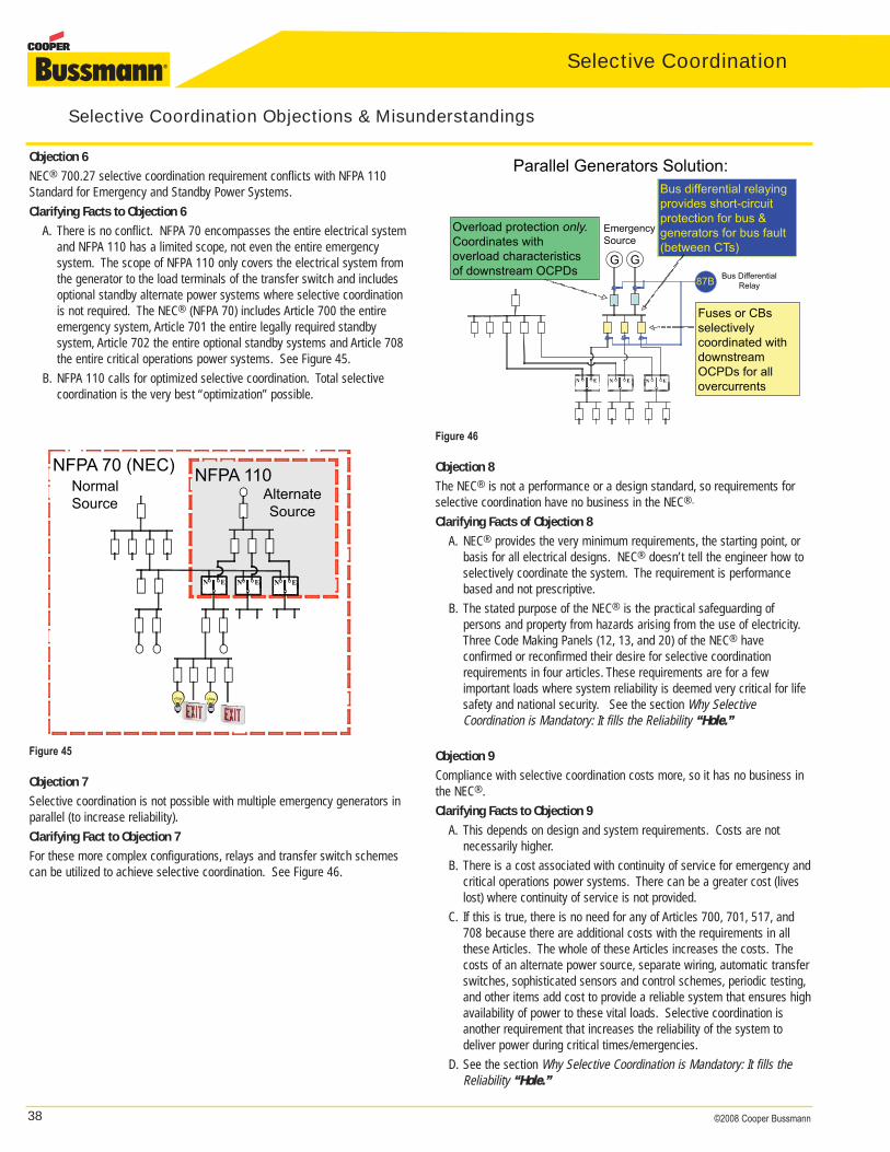
38 ©2008 Cooper Bussmann
Selective Coordination
Objection 6
NEC® 700.27 selective coordination requirement conflicts with NFPA 110Standard for Emergency and Standby Power Systems.Clarifying Facts to Objection 6
A. There is no conflict. NFPA 70 encompasses the entire electrical systemand NFPA 110 has a limited scope, not even the entire emergency system. The scope of NFPA 110 only covers the electrical system from the generator to the load terminals of the transfer switch and includes optional standby alternate power systems where selective coordination is not required. The NEC® (NFPA 70) includes Article 700 the entire emergency system, Article 701 the entire legally required standby system, Article 702 the entire optional standby systems and Article 708 the entire critical operations power systems. See Figure 45.
B. NFPA 110 calls for optimized selective coordination. Total selective coordination is the very best “optimization” possible.
NFPA 110AlternateSource
N E
NormalSource
N E N E
NFPA 70 (NEC)
Figure 45
Objection 7
Selective coordination is not possible with multiple emergency generators inparallel (to increase reliability).Clarifying Fact to Objection 7
For these more complex configurations, relays and transfer switch schemescan be utilized to achieve selective coordination. See Figure 46.
NormalSource
Parallel Generators Solution:
N E N E N E
G
87B
G
Bus differential relayingprovides short-circuitprotection for bus &generators for bus fault(between CTs)
Fuses or CBsselectivelycoordinated withdownstreamOCPDs for allovercurrents
Overload protection only.Coordinates withoverload characteristicsof downstream OCPDs
EmergencySource
Bus DifferentialRelay
Figure 46
Objection 8
The NEC® is not a performance or a design standard, so requirements forselective coordination have no business in the NEC®.
Clarifying Facts of Objection 8
A. NEC® provides the very minimum requirements, the starting point, or basis for all electrical designs. NEC® doesn’t tell the engineer how to selectively coordinate the system. The requirement is performance based and not prescriptive.
B. The stated purpose of the NEC® is the practical safeguarding of persons and property from hazards arising from the use of electricity.Three Code Making Panels (12, 13, and 20) of the NEC® have confirmed or reconfirmed their desire for selective coordination requirements in four articles. These requirements are for a few important loads where system reliability is deemed very critical for life safety and national security. See the section Why Selective Coordination is Mandatory: It fills the Reliability “Hole.”
Objection 9
Compliance with selective coordination costs more, so it has no business inthe NEC®.Clarifying Facts to Objection 9
A. This depends on design and system requirements. Costs are not necessarily higher.
B. There is a cost associated with continuity of service for emergency andcritical operations power systems. There can be a greater cost (lives lost) where continuity of service is not provided.
C. If this is true, there is no need for any of Articles 700, 701, 517, and 708 because there are additional costs with the requirements in all these Articles. The whole of these Articles increases the costs. The costs of an alternate power source, separate wiring, automatic transfer switches, sophisticated sensors and control schemes, periodic testing,and other items add cost to provide a reliable system that ensures high availability of power to these vital loads. Selective coordination is another requirement that increases the reliability of the system to deliver power during critical times/emergencies.
D. See the section Why Selective Coordination is Mandatory: It fills the Reliability “Hole.”
Selective Coordination Objections & Misunderstandings
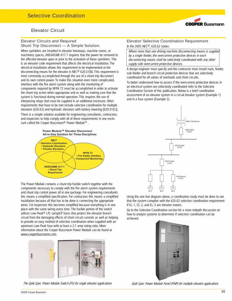
39©2008 Cooper Bussmann
Elevator Circuits and Required Shunt Trip Disconnect — A Simple Solution.When sprinklers are installed in elevator hoistways, machine rooms, ormachinery spaces, ANSI/ASME A17.1 requires that the power be removed tothe affected elevator upon or prior to the activation of these sprinklers. Thisis an elevator code requirement that affects the electrical installation. The electrical installation allows this requirement to be implemented at the disconnecting means for the elevator in NEC® 620.51(B). This requirement ismost commonly accomplished through the use of a shunt trip disconnectand its own control power. To make this situation even more complicated,interface with the fire alarm system along with the monitoring of components required by NFPA 72 must be accomplished in order to activatethe shunt trip action when appropriate and as well as making sure that thesystem is functional during normal operation. This requires the use of interposing relays that must be supplied in an additional enclosure. Otherrequirements that have to be met include selective coordination for multipleelevators (620.62) and hydraulic elevators with battery lowering [620.91(C)].There is a simple solution available for engineering consultants, contractors,and inspectors to help comply with all of these requirements in one enclo-sure called the Cooper Bussmann® Power Module™.
Elevator Selective Coordination RequirementIn the 2005 NEC®, 620.62 states:
Where more than one driving machine disconnecting means is suppliedby a single feeder, the overcurrent protective devices in each disconnecting means shall be selectively coordinated with any othersupply side overcurrent protective devices.
A design engineer must specify and the contractor must install main, feeder,sub-feeder and branch circuit protective devices that are selectively coordinated for all values of overloads and short-circuits.To better understand how to assess if the overcurrent protective devices inan electrical system are selectively coordinated refer to the SelectiveCoordination Section of this publication. Below is a brief coordination assessment of an elevator system in a circuit breaker system (Example 1)and in a fuse system (Example 2).
Elevator Circuit
NEC®
• Selective Coordination• Hydraulic Elevators• Traction Elevators
NFPA 72• Fire Safety Interface
• Component Monitoring
ANSI/ASME A17.1• Shunt TripRequirement
Power Module™ Elevator DisconnectAll-in-One Solution for Three Disciplines
The Power Module contains a shunt trip fusible switch together with the components necessary to comply with the fire alarm system requirementsand shunt trip control power all in one package. For engineering consultantsthis means a simplified specification. For contractors this means a simplified installation because all that has to be done is connecting the appropriatewires. For inspectors this becomes simplified because everything is in oneplace with the same wiring every time. The fusible portion of the switch utilizes Low-Peak® LPJ-(amp)SP fuses that protect the elevator branch circuit from the damaging effects of short-circuit currents as well as helpingto provide an easy method of selective coordination when supplied with anupstream Low-Peak fuse with at least a 2:1 amp rating ratio. More information about the Cooper Bussmann Power Module can be found atwww.cooperbussmann.com.
Using the one-line diagram above, a coordination study must be done to seethat the system complies with the 620.62 selective coordination requirementif EL-1, EL-2, and EL-3 are elevator motors.Go to the Selective Coordination section for a more indepth discussion onhow to analyze systems to determine if selective coordination can beachieved.
The Quik-Spec Power Module Switch (PS) for single elevator applications Quik-Spec Power Module Panel (PMP) for multiple elevator applications
Selective Coordination
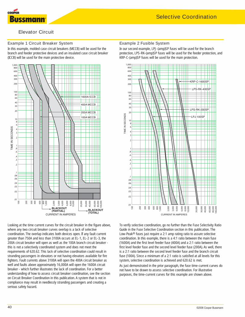
40 ©2008 Cooper Bussmann
Selective Coordination
Example 1 Circuit Breaker SystemIn this example, molded case circuit breakers (MCCB) will be used for thebranch and feeder protective devices and an insulated case circuit breaker(ICCB) will be used for the main protective device.
Example 2 Fusible SystemIn our second example, LPJ-(amp)SP fuses will be used for the branch protection, LPS-RK-(amp)SP fuses will be used for the feeder protection, andKRP-C-(amp)SP fuses will be used for the main protection.
Elevator Circuit
1600A ICCB
200A MCCB
400A MCCB
BLACKOUT(TOTAL)
100A MCCB
BLACKOUT(PARTIAL)
CURRENT IN AMPERES
1,000800600
400300
200
1008060
4030
20
1086
43
2
1.8.6
.4
.3
.2
.1.08.06
.04
.03
.02
.01
TIM
EIN
SE
CO
ND
S
100,
000
80,0
0060
,000
40,0
00
30,0
00
20,0
00
10,0
008,
000
6,00
0
4,00
0
3,00
0
2,00
0
1,00
080
060
0
400
300
200
100
TIM
EIN
SE
CO
ND
S
1,000800
600
400300
200
1008060
40
30
20
1086
43
2
1.8.6
.4
.3
.2
.1.08.06
.04
.03
.02
.01
CURRENT IN AMPERES10
0,00
080
,000
60,0
00
10,0
00
40,0
0030
,000
20,0
00
8,00
06,
000
4,00
0
3,00
0
2,00
0
1,00
080
060
0
400
300
200
100
LPS-RK-200SP
LPS-RK-400SP
KRP-C-1600SP
LPJ-100SP
Looking at the time current curves for the circuit breaker in the figure above,where any two circuit breaker curves overlap is a lack of selective coordination. The overlap indicates both devices open. If any fault currentgreater than 750A and less than 3100A occurs at EL-1, EL-2 or EL-3, the200A circuit breaker will open as well as the 100A branch circuit breaker -this is not a selectively coordinated system and does not meet the requirements of 620.62. This lack of selective coordination could result instranding passengers in elevators or not having elevators available for firefighters. Fault currents above 3100A will open the 400A circuit breaker aswell and faults above approximately 16,000A will open the 1600A circuitbreaker - which further illustrates the lack of coordination. For a betterunderstanding of how to assess circuit breaker coordination, see the sectionon Circuit Breaker Coordination in this publication. A system that is not incompliance may result in needlessly stranding passengers and creating aserious safety hazard.
To verify selective coordination, go no further than the Fuse Selectivity RatioGuide in the Fuse Selective Coordination section in this publication. The Low-Peak® fuses just require a 2:1 amp rating ratio to assure selectivecoordination. In this example, there is a 4:1 ratio between the main fuse(1600A) and the first level feeder fuse (400A) and a 2:1 ratio between thefirst level feeder fuse and the second level feeder fuse (200A). As well, thereis a 2:1 ratio between the second level feeder fuse and the branch circuitfuse (100A). Since a minimum of a 2:1 ratio is satisfied at all levels for thissystem, selective coordination is achieved and 620.62 is met.As just demonstrated in the prior paragraph, the fuse time-current curves donot have to be drawn to assess selective coordination. For illustrative purposes, the time-current curves for this example are shown above.
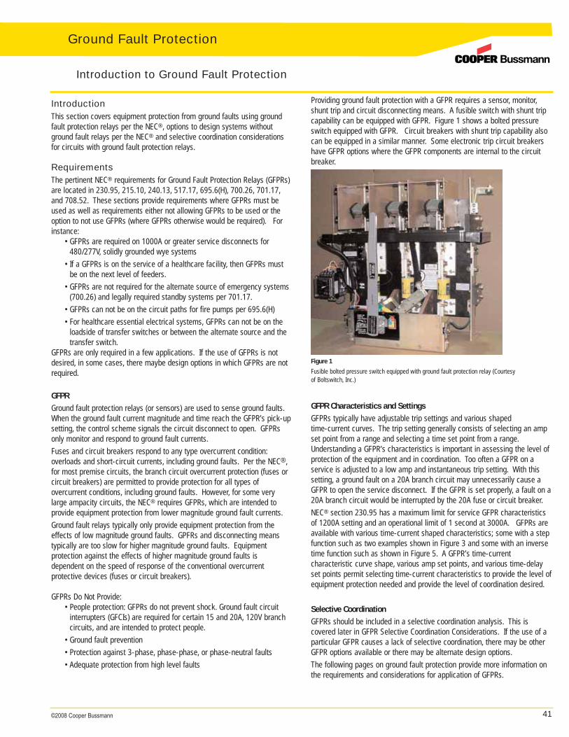
41©2008 Cooper Bussmann
Selective CoordinationGround Fault Protection
IntroductionThis section covers equipment protection from ground faults using groundfault protection relays per the NEC®, options to design systems withoutground fault relays per the NEC® and selective coordination considerationsfor circuits with ground fault protection relays.
RequirementsThe pertinent NEC® requirements for Ground Fault Protection Relays (GFPRs)are located in 230.95, 215.10, 240.13, 517.17, 695.6(H), 700.26, 701.17,and 708.52. These sections provide requirements where GFPRs must beused as well as requirements either not allowing GFPRs to be used or theoption to not use GFPRs (where GFPRs otherwise would be required). Forinstance:
• GFPRs are required on 1000A or greater service disconnects for 480/277V, solidly grounded wye systems
• If a GFPRs is on the service of a healthcare facility, then GFPRs must be on the next level of feeders.
• GFPRs are not required for the alternate source of emergency systems (700.26) and legally required standby systems per 701.17.
• GFPRs can not be on the circuit paths for fire pumps per 695.6(H) • For healthcare essential electrical systems, GFPRs can not be on the
loadside of transfer switches or between the alternate source and the transfer switch.
GFPRs are only required in a few applications. If the use of GFPRs is notdesired, in some cases, there maybe design options in which GFPRs are notrequired.
GFPR
Ground fault protection relays (or sensors) are used to sense ground faults.When the ground fault current magnitude and time reach the GFPR’s pick-upsetting, the control scheme signals the circuit disconnect to open. GFPRsonly monitor and respond to ground fault currents.Fuses and circuit breakers respond to any type overcurrent condition:overloads and short-circuit currents, including ground faults. Per the NEC®,for most premise circuits, the branch circuit overcurrent protection (fuses or circuit breakers) are permitted to provide protection for all types of overcurrent conditions, including ground faults. However, for some verylarge ampacity circuits, the NEC® requires GFPRs, which are intended to provide equipment protection from lower magnitude ground fault currents.Ground fault relays typically only provide equipment protection from theeffects of low magnitude ground faults. GPFRs and disconnecting meanstypically are too slow for higher magnitude ground faults. Equipment protection against the effects of higher magnitude ground faults is dependent on the speed of response of the conventional overcurrent protective devices (fuses or circuit breakers).
GFPRs Do Not Provide:• People protection: GFPRs do not prevent shock. Ground fault circuit
interrupters (GFCIs) are required for certain 15 and 20A, 120V branch circuits, and are intended to protect people.
• Ground fault prevention• Protection against 3-phase, phase-phase, or phase-neutral faults• Adequate protection from high level faults
Providing ground fault protection with a GFPR requires a sensor, monitor,shunt trip and circuit disconnecting means. A fusible switch with shunt tripcapability can be equipped with GFPR. Figure 1 shows a bolted pressureswitch equipped with GFPR. Circuit breakers with shunt trip capability alsocan be equipped in a similar manner. Some electronic trip circuit breakershave GFPR options where the GFPR components are internal to the circuitbreaker.
Figure 1
Fusible bolted pressure switch equipped with ground fault protection relay (Courtesy of Boltswitch, Inc.)
GFPR Characteristics and Settings
GFPRs typically have adjustable trip settings and various shaped time-current curves. The trip setting generally consists of selecting an ampset point from a range and selecting a time set point from a range.Understanding a GFPR’s characteristics is important in assessing the level ofprotection of the equipment and in coordination. Too often a GFPR on a service is adjusted to a low amp and instantaneous trip setting. With thissetting, a ground fault on a 20A branch circuit may unnecessarily cause aGFPR to open the service disconnect. If the GFPR is set properly, a fault on a20A branch circuit would be interrupted by the 20A fuse or circuit breaker.NEC® section 230.95 has a maximum limit for service GFPR characteristicsof 1200A setting and an operational limit of 1 second at 3000A. GFPRs areavailable with various time-current shaped characteristics; some with a stepfunction such as two examples shown in Figure 3 and some with an inversetime function such as shown in Figure 5. A GFPR’s time-current characteristic curve shape, various amp set points, and various time-delayset points permit selecting time-current characteristics to provide the level of equipment protection needed and provide the level of coordination desired.
Selective Coordination
GFPRs should be included in a selective coordination analysis. This is covered later in GFPR Selective Coordination Considerations. If the use of aparticular GFPR causes a lack of selective coordination, there may be otherGFPR options available or there may be alternate design options.The following pages on ground fault protection provide more information onthe requirements and considerations for application of GFPRs.
Introduction to Ground Fault Protection
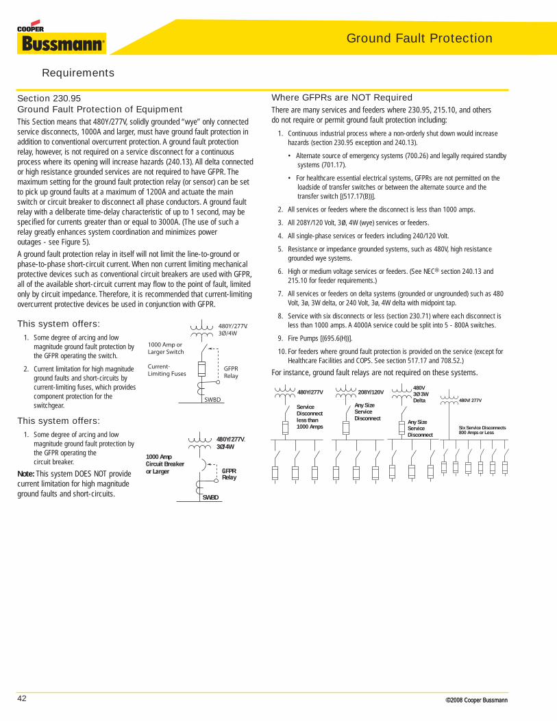
42 ©2008 Cooper Bussmann©2008 Cooper Bussmann
Ground Fault Protection
Section 230.95 Ground Fault Protection of EquipmentThis Section means that 480Y/277V, solidly grounded “wye” only connectedservice disconnects, 1000A and larger, must have ground fault protection inaddition to conventional overcurrent protection. A ground fault protectionrelay, however, is not required on a service disconnect for a continuousprocess where its opening will increase hazards (240.13). All delta connectedor high resistance grounded services are not required to have GFPR. Themaximum setting for the ground fault protection relay (or sensor) can be setto pick up ground faults at a maximum of 1200A and actuate the mainswitch or circuit breaker to disconnect all phase conductors. A ground faultrelay with a deliberate time-delay characteristic of up to 1 second, may bespecified for currents greater than or equal to 3000A. (The use of such arelay greatly enhances system coordination and minimizes power outages - see Figure 5).A ground fault protection relay in itself will not limit the line-to-ground orphase-to-phase short-circuit current. When non current limiting mechanicalprotective devices such as conventional circuit breakers are used with GFPR,all of the available short-circuit current may flow to the point of fault, limitedonly by circuit impedance. Therefore, it is recommended that current-limitingovercurrent protective devices be used in conjunction with GFPR.
This system offers:1. Some degree of arcing and low
magnitude ground fault protection bythe GFPR operating the switch.
2. Current limitation for high magnitudeground faults and short-circuits by current-limiting fuses, which providescomponent protection for theswitchgear.
This system offers:1. Some degree of arcing and low
magnitude ground fault protection bythe GFPR operating the circuit breaker.
Note: This system DOES NOT providecurrent limitation for high magnitudeground faults and short-circuits.
Requirements
480V/ 277V
Six Service Disconnects800 Amps or Less
480V3Ø 3WDelta
Any SizeServiceDisconnect
ServiceDisconnectless than 1000 Amps
480Y/277V 208Y/120V
Any SizeServiceDisconnect
480Y/277V.3Ø/4W
GFPRRelay
1000 Amp orLarger Switch
Current-Limiting Fuses
SWBD
SWBD
480Y/277V.3Ø/4W
GFPRRelay
1000 AmpCircuit Breakeror Larger
Where GFPRs are NOT RequiredThere are many services and feeders where 230.95, 215.10, and others do not require or permit ground fault protection including:
1. Continuous industrial process where a non-orderly shut down would increase hazards (section 230.95 exception and 240.13).
• Alternate source of emergency systems (700.26) and legally required standby systems (701.17).
• For healthcare essential electrical systems, GFPRs are not permitted on the loadside of transfer switches or between the alternate source and the transfer switch [(517.17(B))].
2. All services or feeders where the disconnect is less than 1000 amps.
3. All 208Y/120 Volt, 3ø, 4W (wye) services or feeders.
4. All single-phase services or feeders including 240/120 Volt.
5. Resistance or impedance grounded systems, such as 480V, high resistancegrounded wye systems.
6. High or medium voltage services or feeders. (See NEC® section 240.13 and215.10 for feeder requirements.)
7. All services or feeders on delta systems (grounded or ungrounded) such as 480Volt, 3ø, 3W delta, or 240 Volt, 3ø, 4W delta with midpoint tap.
8. Service with six disconnects or less (section 230.71) where each disconnect isless than 1000 amps. A 4000A service could be split into 5 - 800A switches.
9. Fire Pumps [(695.6(H))].
10. For feeders where ground fault protection is provided on the service (except forHealthcare Facilities and COPS. See section 517.17 and 708.52.)
For instance, ground fault relays are not required on these systems.
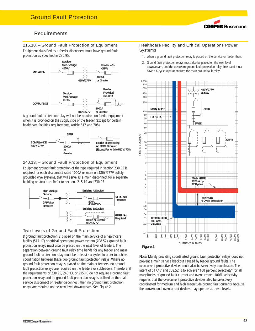
43©2008 Cooper Bussmann©2008 Cooper Bussmann
215.10. – Ground Fault Protection of EquipmentEquipment classified as a feeder disconnect must have ground fault protection as specified in 230.95.
Requirements
COMPLIANCE480Y/277V
Feeder of any ratingno GFPR Required(Except Per Article 517 & 708)
GFPR
1000AorGreater
VIOLATION
COMPLIANCE
480Y/277V
FeederProvidedw/GFPR
1000Aor Greater
Med. Voltage4160V
480Y/277V
Feeder w/oGFPR
1000Aor Greater
Service
Med. Voltage4160V
Service
A ground fault protection relay will not be required on feeder equipmentwhen it is provided on the supply side of the feeder (except for certainhealthcare facilities requirements, Article 517 and 708).
240.13. – Ground Fault Protection of EquipmentEquipment ground fault protection of the type required in section 230.95 isrequired for each disconnect rated 1000A or more on 480Y/277V solidlygrounded wye systems, that will serve as a main disconnect for a separatebuilding or structure. Refer to sections 215.10 and 230.95.
Two Levels of Ground Fault Protection If ground fault protection is placed on the main service of a healthcare facility (517.17) or critical operations power system (708.52), ground faultprotection relays must also be placed on the next level of feeders. The separation between ground fault relay time bands for any feeder and mainground fault protection relay must be at least six cycles in order to achievecoordination between these two ground fault protection relays. Where noground fault protection relay is placed on the main or feeders, no groundfault protection relays are required on the feeders or subfeeders. Therefore, ifthe requirements of 230.95, 240.13, or 215.10 do not require a ground faultprotection relay and no ground fault protection relay is utilized on the mainservice disconnect or feeder disconnect, then no ground fault protectionrelays are required on the next level downstream. See Figure 2.
Healthcare Facility and Critical Operations PowerSystems
1. When a ground fault protection relay is placed on the service or feeder then,
2. Ground fault protection relays must also be placed on the next level downstream, and the upstream ground fault protection relay time band musthave a 6 cycle separation from the main ground fault relay.
Note: Merely providing coordinated ground fault protection relays does notprevent a main service blackout caused by feeder ground faults. The overcurrent protective devices must also be selectively coordinated. Theintent of 517.17 and 708.52 is to achieve “100 percent selectivity” for allmagnitudes of ground fault current and overcurrents. 100% selectivityrequires that the overcurrent protective devices also be selectively coordinated for medium and high magnitude ground fault currents becausethe conventional overcurrent devices may operate at these levels.
High VoltageService
Building A Service
800A480Y/277V
Building B Service
1000A or Greater480Y/277V
GFPR NotRequired
Required
Required
GFPR Not
GFPR Not
TIM
E IN
SE
CO
ND
S
1,000800
600
400300
200
1008060
40
30
20
1086
43
2
1.8.6
.4
.3
.2
.1.08.06
.04
.03
.02
.01
CURRENT IN AMPS
100,
000
80,0
0060
,000
10,0
00
40,0
0030
,000
20,0
00
8,00
06,
000
4,00
0
3,00
0
2,00
0
1,00
080
060
0
400
300
200
100
MAIN GFPR1200 Amp12 Cycles
Minimum6 Cycle Separation
FEEDER GFPR800 Amp2 Cycles
MAIN GFPR
FDR GFPR
480Y/277V.3Ø/4W
GFPR
SWBD
GFPR
Figure 2
Ground Fault Protection
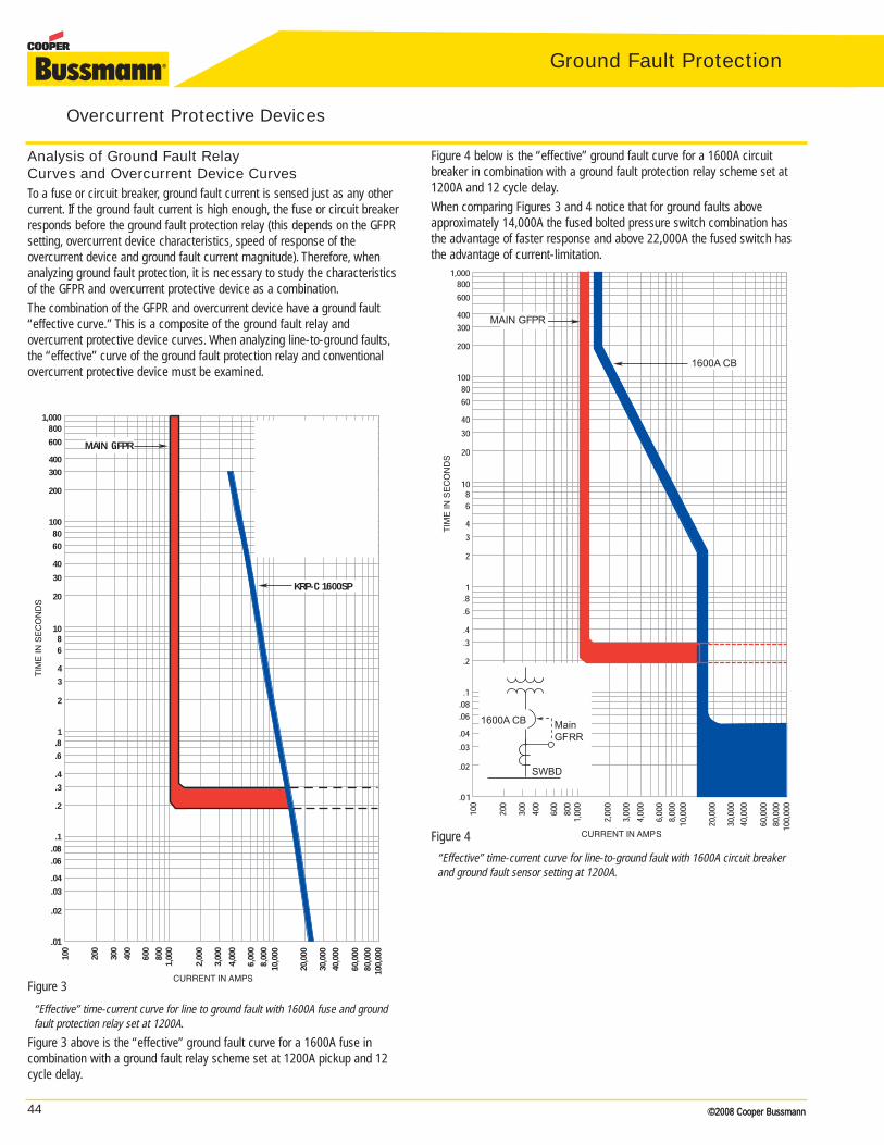
44 ©2008 Cooper Bussmann
TIM
E IN
SE
CO
ND
S
1,000800
600
400300
200
1008060
40
30
20
1086
4
3
2
1.8.6
.4
.3
.2
.1.08.06
.04
.03
.02
.01
CURRENT IN AMPS
100,
000
80,0
0060
,000
10,0
00
40,0
0030
,000
20,0
00
8,00
06,
000
4,00
0
3,00
0
2,00
0
1,00
080
0
600
400
300
200
100
MAIN GFPR
KRP-C 1600SP
MainG.F.R.KRP-C1600SP
©2008 Cooper Bussmann
Ground Fault Protection
Analysis of Ground Fault Relay Curves and Overcurrent Device CurvesTo a fuse or circuit breaker, ground fault current is sensed just as any othercurrent. If the ground fault current is high enough, the fuse or circuit breakerresponds before the ground fault protection relay (this depends on the GFPRsetting, overcurrent device characteristics, speed of response of the overcurrent device and ground fault current magnitude). Therefore, whenanalyzing ground fault protection, it is necessary to study the characteristicsof the GFPR and overcurrent protective device as a combination.The combination of the GFPR and overcurrent device have a ground fault“effective curve.” This is a composite of the ground fault relay and overcurrent protective device curves. When analyzing line-to-ground faults,the “effective” curve of the ground fault protection relay and conventionalovercurrent protective device must be examined.
Overcurrent Protective Devices
“Effective” time-current curve for line to ground fault with 1600A fuse and groundfault protection relay set at 1200A.
Figure 3 above is the “effective” ground fault curve for a 1600A fuse in combination with a ground fault relay scheme set at 1200A pickup and 12cycle delay.
Figure 4 below is the “effective” ground fault curve for a 1600A circuit breaker in combination with a ground fault protection relay scheme set at1200A and 12 cycle delay.When comparing Figures 3 and 4 notice that for ground faults above approximately 14,000A the fused bolted pressure switch combination hasthe advantage of faster response and above 22,000A the fused switch hasthe advantage of current-limitation.
“Effective” time-current curve for line-to-ground fault with 1600A circuit breakerand ground fault sensor setting at 1200A.
Figure 3
Figure 4
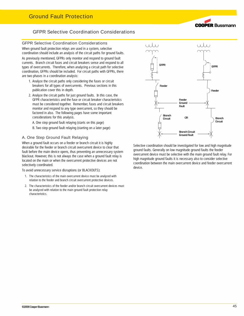
45©2008 Cooper Bussmann©2008 Cooper Bussmann
GFPR Selective Coordination ConsiderationsWhen ground fault protection relays are used in a system, selective coordination should include an analysis of the circuit paths for ground faults.As previously mentioned, GFPRs only monitor and respond to ground faultcurrents. Branch circuit fuses and circuit breakers sense and respond to alltypes of overcurrents. Therefore, when analyzing a circuit path for selectivecoordination, GFPRs should be included. For circuit paths with GFPRs, thereare two phases in a coordination analysis:
1. Analyze the circuit paths only considering the fuses or circuit breakers for all types of overcurrents. Previous sections in this publication cover this in depth.
2. Analyze the circuit paths for just ground faults. In this case, the GFPR characteristics and the fuse or circuit breaker characteristics must be considered together. Remember, fuses and circuit breakers monitor and respond to any type overcurrent, so they should be factored in also. The following pages have some important considerations for this analysis.A. One step ground fault relaying (starts on this page)B. Two step ground fault relaying (starting on a later page)
A. One Step Ground Fault RelayingWhen a ground fault occurs on a feeder or branch circuit it is highly desirable for the feeder or branch circuit overcurrent device to clear thatfault before the main device opens, thus preventing an unnecessary systemblackout. However, this is not always the case when a ground fault relay islocated on the main or when the overcurrent protective devices are notselectively coordinated.To avoid unnecessary service disruptions (or BLACKOUTS):
1. The characteristics of the main overcurrent device must be analyzed with relation to the feeder and branch circuit overcurrent protective devices.
2. The characteristics of the feeder and/or branch circuit overcurrent devices mustbe analyzed with relation to the main ground fault protection relay characteristics.
Ground Fault Protection
GFPR Selective Coordination Considerations
GFPR
Feeder
BranchCircuit
Feeder
BranchCircuit
FeederGroundFault
Branch CircuitGround Fault
OR
GFPR
Selective coordination should be investigated for low and high magnitudeground faults. Generally on low magnitude ground faults the feeder overcurrent device must be selective with the main ground fault relay. Forhigh magnitude ground faults it is necessary also to consider selective coordination between the main overcurrent device and feeder overcurrentdevice.

46 ©2008 Cooper Bussmann©2008 Cooper Bussmann
Ground Fault Protection
Low Magnitude Ground Faults on Feeders — One Step Ground Fault Relaying.For low magnitude feeder ground faults, the feeder overcurrent protectivedevice can clear the circuit without disrupting the main service if the feederovercurrent device lies to the left of the ground fault protection relay anddoes not cross at any point.In Figures 5 and 6, the ground fault protection relay located on the main hasan operating time-delay of 18 cycles and 1200A pickup. Its inverse-timecharacteristic with the maximum 1 second opening time at 3000A improvesselective coordination with downstream devices.
Fuse System
GFPR Selective Coordination Considerations
MAIN GRPR
MAIN GFPR
MainGFPR
Selective coordination considerations for low magnitude feeder ground faults.Longer GFPR relay delay permits larger feeder fuse to coordinate with main relay.
Figure 5 illustrates that an inverse-time main ground fault relay may permit alarger size feeder fuse to selectively coordinate with the ground fault relay. Inthis case, the inverse time ground fault relay is set at 1200A and 18 cycledelay. A LPS-RK-200SP amp feeder fuse coordinates with this main groundfault relay. A JKS-400A feeder fuse, which is a non time-delay fuse,coordinates with this same main GFPR (figure not included).
Coordination considerations for low magnitude feeder ground faults. Consider mainground fault relay and feeder overcurrent device. A lack of coordination exists forground faults between 1200A and 1800A.
Circuit Breaker SystemFigure 6 illustrates that for some low magnitude ground faults this 200A circuit breaker will not coordinate with the ground fault relay. If this circuitbreaker has an adjustable instaneous trip, it may be possible to lower thesetting and achieve coordination with the GFPR.
Figure 5
Figure 6
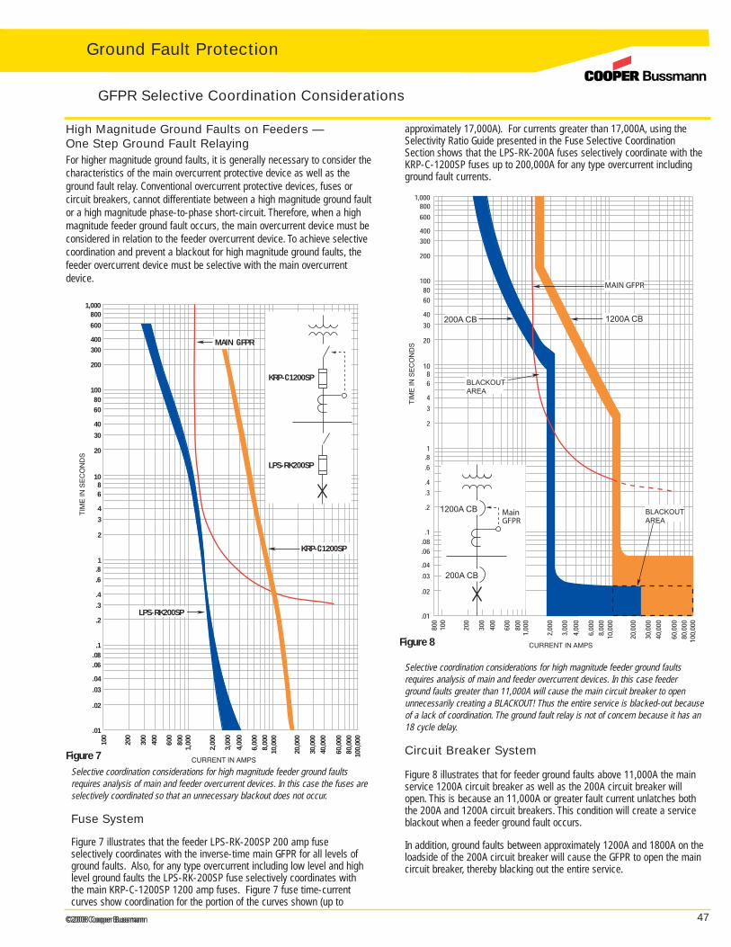
47©2008 Cooper Bussmann©2008 Cooper Bussmann
High Magnitude Ground Faults on Feeders — One Step Ground Fault RelayingFor higher magnitude ground faults, it is generally necessary to consider thecharacteristics of the main overcurrent protective device as well as theground fault relay. Conventional overcurrent protective devices, fuses or circuit breakers, cannot differentiate between a high magnitude ground faultor a high magnitude phase-to-phase short-circuit. Therefore, when a highmagnitude feeder ground fault occurs, the main overcurrent device must beconsidered in relation to the feeder overcurrent device. To achieve selectivecoordination and prevent a blackout for high magnitude ground faults, thefeeder overcurrent device must be selective with the main overcurrentdevice.
Ground Fault Protection
GFPR Selective Coordination Considerations
LPS-RK200SP
MAINMAIN GFPR
KRP-C1200SP
TIM
E IN
SE
CO
ND
S
1,000800
600
400300
200
1008060
40
30
20
1086
4
3
2
1.8.6
.4
.3
.2
.1.08.06
.04
.03
.02
.01
CURRENT IN AMPS
100,
000
80,0
0060
,000
10,0
00
40,0
0030
,000
20,0
00
8,00
06,
000
4,00
0
3,00
0
2,00
0
1,00
080
0
600
400
300
200
100
LPS-RK200SP
KRP-C1200SP
Selective coordination considerations for high magnitude feeder ground faultsrequires analysis of main and feeder overcurrent devices. In this case the fuses areselectively coordinated so that an unnecessary blackout does not occur.
Fuse System
Figure 7 illustrates that the feeder LPS-RK-200SP 200 amp fuse selectively coordinates with the inverse-time main GFPR for all levels ofground faults. Also, for any type overcurrent including low level and highlevel ground faults the LPS-RK-200SP fuse selectively coordinates withthe main KRP-C-1200SP 1200 amp fuses. Figure 7 fuse time-currentcurves show coordination for the portion of the curves shown (up to
approximately 17,000A). For currents greater than 17,000A, using theSelectivity Ratio Guide presented in the Fuse Selective CoordinationSection shows that the LPS-RK-200A fuses selectively coordinate with theKRP-C-1200SP fuses up to 200,000A for any type overcurrent includingground fault currents.
Selective coordination considerations for high magnitude feeder ground faultsrequires analysis of main and feeder overcurrent devices. In this case feederground faults greater than 11,000A will cause the main circuit breaker to openunnecessarily creating a BLACKOUT! Thus the entire service is blacked-out becauseof a lack of coordination. The ground fault relay is not of concern because it has an18 cycle delay.
Circuit Breaker System
Figure 8 illustrates that for feeder ground faults above 11,000A the mainservice 1200A circuit breaker as well as the 200A circuit breaker willopen. This is because an 11,000A or greater fault current unlatches boththe 200A and 1200A circuit breakers. This condition will create a serviceblackout when a feeder ground fault occurs.
In addition, ground faults between approximately 1200A and 1800A on theloadside of the 200A circuit breaker will cause the GFPR to open the maincircuit breaker, thereby blacking out the entire service.
Figure 7
MainGFPR
MAIN GFPR
Figure 8
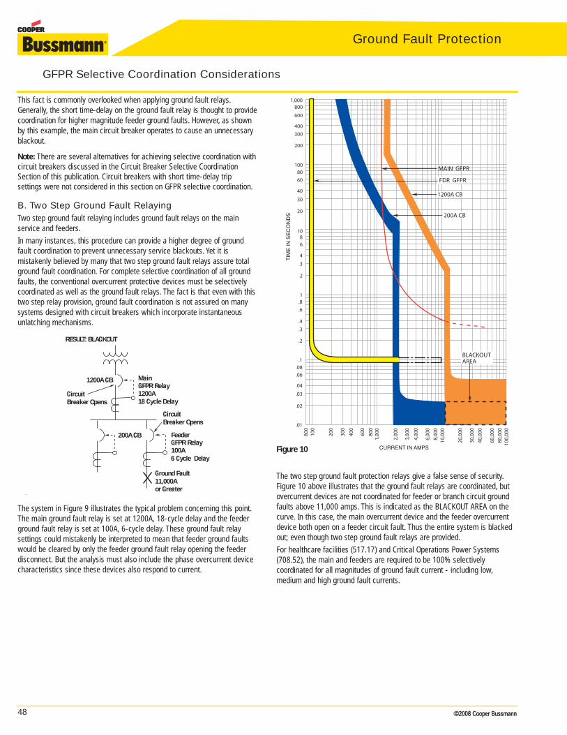
48 ©2008 Cooper Bussmann©2008 Cooper Bussmann
Ground Fault Protection
GFPR Selective Coordination Considerations
FDR GFPR
MAIN GFPR
BLACKOUTAREA
1200A CB
200A CB
TIM
E IN
SE
CO
ND
S
1,000800
600
400300
200
1008060
40
30
20
1086
4
3
2
1.8.6
.4
.3
.2
.1.08.06
.04
.03
.02
.01
CURRENT IN AMPS
100,
000
80,0
0060
,000
10,0
00
40,0
0030
,000
20,0
00
8,00
06,
000
4,00
0
3,00
0
2,00
0
1,00
080
060
0
400
300
200
100
800
The two step ground fault protection relays give a false sense of security.Figure 10 above illustrates that the ground fault relays are coordinated, butovercurrent devices are not coordinated for feeder or branch circuit groundfaults above 11,000 amps. This is indicated as the BLACKOUT AREA on thecurve. In this case, the main overcurrent device and the feeder overcurrentdevice both open on a feeder circuit fault. Thus the entire system is blackedout; even though two step ground fault relays are provided.For healthcare facilities (517.17) and Critical Operations Power Systems(708.52), the main and feeders are required to be 100% selectively coordinated for all magnitudes of ground fault current - including low,medium and high ground fault currents.
This fact is commonly overlooked when applying ground fault relays.Generally, the short time-delay on the ground fault relay is thought to providecoordination for higher magnitude feeder ground faults. However, as shownby this example, the main circuit breaker operates to cause an unnecessaryblackout.
Note: There are several alternatives for achieving selective coordination withcircuit breakers discussed in the Circuit Breaker Selective CoordinationSection of this publication. Circuit breakers with short time-delay trip settings were not considered in this section on GFPR selective coordination.
B. Two Step Ground Fault RelayingTwo step ground fault relaying includes ground fault relays on the main service and feeders.In many instances, this procedure can provide a higher degree of groundfault coordination to prevent unnecessary service blackouts. Yet it is mistakenly believed by many that two step ground fault relays assure totalground fault coordination. For complete selective coordination of all groundfaults, the conventional overcurrent protective devices must be selectivelycoordinated as well as the ground fault relays. The fact is that even with thistwo step relay provision, ground fault coordination is not assured on manysystems designed with circuit breakers which incorporate instantaneousunlatching mechanisms.
The system in Figure 9 illustrates the typical problem concerning this point.The main ground fault relay is set at 1200A, 18-cycle delay and the feederground fault relay is set at 100A, 6-cycle delay. These ground fault relay settings could mistakenly be interpreted to mean that feeder ground faultswould be cleared by only the feeder ground fault relay opening the feeder disconnect. But the analysis must also include the phase overcurrent devicecharacteristics since these devices also respond to current.
Figure 10
Figure 9
Feeder
100A6 Cycle Delay
MainGFPR Relay1200A18 Cycle Delay
200A CB
Ground Fault11,000Aor Greater
RESULT: BLACKOUT
CircuitBreaker Opens
1200A CB
CircuitBreaker Opens
GFPR Relay
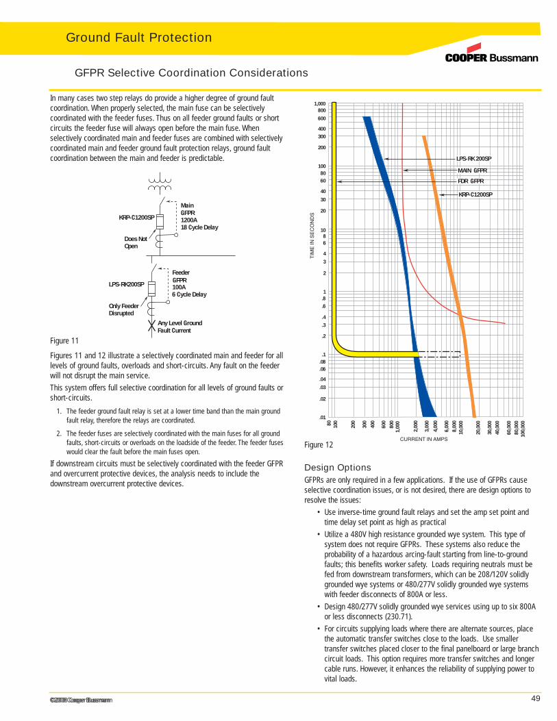
49©2008 Cooper Bussmann©2008 Cooper Bussmann
In many cases two step relays do provide a higher degree of ground faultcoordination. When properly selected, the main fuse can be selectively coordinated with the feeder fuses. Thus on all feeder ground faults or short circuits the feeder fuse will always open before the main fuse. When selectively coordinated main and feeder fuses are combined with selectivelycoordinated main and feeder ground fault protection relays, ground faultcoordination between the main and feeder is predictable.
Ground Fault Protection
GFPR Selective Coordination Considerations
MainGFPR1200A18 Cycle Delay
KRP-C1200SP
Feeder
100A6 Cycle Delay
Any Level GroundFault Current
Does NotOpen
LPS-RK200SP
Only FeederDisrupted
GFPR
CURRENT IN AMPS
100,
000
80,0
0060
,000
10,0
00
40,0
0030
,000
20,0
00
8,00
06,
000
4,00
0
3,00
0
2,00
0
1,00
080
0
600
400
300
200
10080
MAIN GFPR
FDR GFPR
TIM
E IN
SE
CO
ND
S
1,000800
600
400300
200
1008060
40
30
20
1086
4
3
2
1.8.6
.4
.3
.2
.1.08.06
.04
.03
.02
.01
LPS-RK 200SP
KRP-C1200SP
Figures 11 and 12 illustrate a selectively coordinated main and feeder for alllevels of ground faults, overloads and short-circuits. Any fault on the feederwill not disrupt the main service.This system offers full selective coordination for all levels of ground faults orshort-circuits.
1. The feeder ground fault relay is set at a lower time band than the main groundfault relay, therefore the relays are coordinated.
2. The feeder fuses are selectively coordinated with the main fuses for all groundfaults, short-circuits or overloads on the loadside of the feeder. The feeder fuseswould clear the fault before the main fuses open.
If downstream circuits must be selectively coordinated with the feeder GFPRand overcurrent protective devices, the analysis needs to include the downstream overcurrent protective devices.
Figure 11
Design OptionsGFPRs are only required in a few applications. If the use of GFPRs causeselective coordination issues, or is not desired, there are design options toresolve the issues:
• Use inverse-time ground fault relays and set the amp set point and time delay set point as high as practical
• Utilize a 480V high resistance grounded wye system. This type of system does not require GFPRs. These systems also reduce the probability of a hazardous arcing-fault starting from line-to-ground faults; this benefits worker safety. Loads requiring neutrals must be fed from downstream transformers, which can be 208/120V solidly grounded wye systems or 480/277V solidly grounded wye systems with feeder disconnects of 800A or less.
• Design 480/277V solidly grounded wye services using up to six 800A or less disconnects (230.71).
• For circuits supplying loads where there are alternate sources, place the automatic transfer switches close to the loads. Use smaller transfer switches placed closer to the final panelboard or large branch circuit loads. This option requires more transfer switches and longer cable runs. However, it enhances the reliability of supplying power to vital loads.
Figure 12

50 ©2008 Cooper Bussmann©2008 Cooper Bussmann
Ground Fault Protection
The Need for Current LimitationIf ground fault protection is required, then the best protection is a switchequipped with a ground fault protection relay scheme, a shunt trip mechanism and current-limiting fuses. The reason is that this system willoffer protection for high magnitude ground faults as well as low magnitudeground faults. Ground fault protection relay schemes and shunt trip mechanisms on switches or circuit breakers can protect equipment againstextensive damage from low magnitude ground faults - this is their intendedpurpose.
Current Limitation
CURRENT IN AMPS
TIM
EIN
SE
CO
ND
S
1600A CB
TIM
E IN
SE
CO
ND
S
1,000800600
400300
200
1008060
40
30
20
1086
4
3
2
1.8.6
.4
.3
.2
.1.08.06
.04
.03
.02
.01
CURRENT IN AMPS
100,
000
80,0
0060
,000
10,0
00
40,0
0030
,000
20,0
00
8,00
06,
000
4,00
0
3,00
0
2,00
0
1,00
080
0
600
400
300
200
100
Clearing characteristic for a 1600A fuse. A 20,000 amp fault is cleared by the KRP-C-1600SP fuse in 0.019 to 0.039 second (between one and two cycles).For currents greater than 25,000A, the fuse enters its current-limiting range.Then the clearing time is less than one half cycle (less than 0.008 second).
Clearing characteristic for 1600A circuit breaker. A 20,000A fault is cleared by the1600A circuit breaker in 0.05 second. The circuit breaker has a fixed operating timefor high values of current. This time is approximately 0.05 second (three cycles).Therefore, high magnitude ground faults and short-circuits are permitted to flow forat least three cycles.
The National Electrical Code® requires ground fault protection for intermediate and high ground faults as well as low grade ground faults. Forhigh magnitude ground faults, ground fault relay schemes operate too slowlyto prevent extensive equipment damage. The main or feeder overcurrentdevices, such as fuses or circuit breakers must clear the circuit.Current-limiting fuses substantially limit the energy let-through for highermagnitude ground faults and thereby offer a higher degree of protection.Conventional circuit breakers are not current-limiting protective devices andduring higher magnitude ground faults can let through large amounts ofdamaging energy.
Figure 13Figure 14