selective laser melting - ailu · pdf file1 selective laser melting developemts in slm...
TRANSCRIPT

1
Selective Laser Melting
Developemts in SLM Equipment d Pand Processes
Dr Chris Sutcliffe R+D Director MTT Technologies Group
Outline
• Introduction
• SLM process• SLM process
• Typical characteristics
• Various applications
• Validation
F t l tf• Future platforms

2
SLM Technology Center - Stone - United Kingdom
Locations
MTT TechnologiesWhitebridge Way,Whitebridge Park, Stone,Staffordshire ST15 8LQ.England
Tel: +44 (0)1785 815651Fax: +44 (0)1785 812115
SLM Technology Center - Lübeck - Germany
Locations
MTT TechnologiesRoggenhorster Strasse 9 cD- 23556 LübeckGermany
Tel. +49 451/16082- 0Fax.+49 451/16082 – 250

3
SLM timeline
1995-1998 Basic Research F&S and Fraunhofer1995 1998 Basic Research F&S and FraunhoferILT, University of Liverpool, University of Texas
1998-2002 F&S Research leading to IP
2002- F&S / MCP partner to develop, produce and market the MCP Realizer
2004 L h f SLM R li 2502004- Launch of SLM Realizer 250
2006 - Launch of SLM Realizer 100
2008- MTT/3DS partner to launch the machines in the USA
SLM timeline

4
SLM timeline
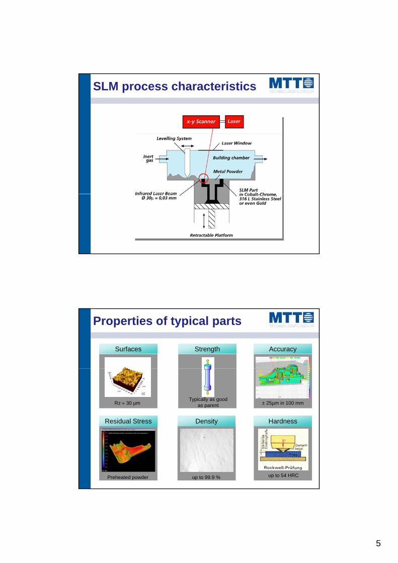
SLM process characteristics
• SLM is a cyclic process consisting of– The application of thin powder layer
– exposure of the powder bed to laser beamexposure of the powder bed to laser beam
– lowering of the build platform
• Typical deposition rates of 5 – 30 cm³/h
• Typical powder particle size of between 10 and 50µm
• Laser powers of 200W and up to 400W (more of this later)
Hi h d f t i f d i il t SLA• High degree of geometric freedom similar to SLA
• Fully automated one-step manufacturing (more of this later)
• Ability to process reactive powders
• Very good levels of powder recyclability
5
SLM process characteristics
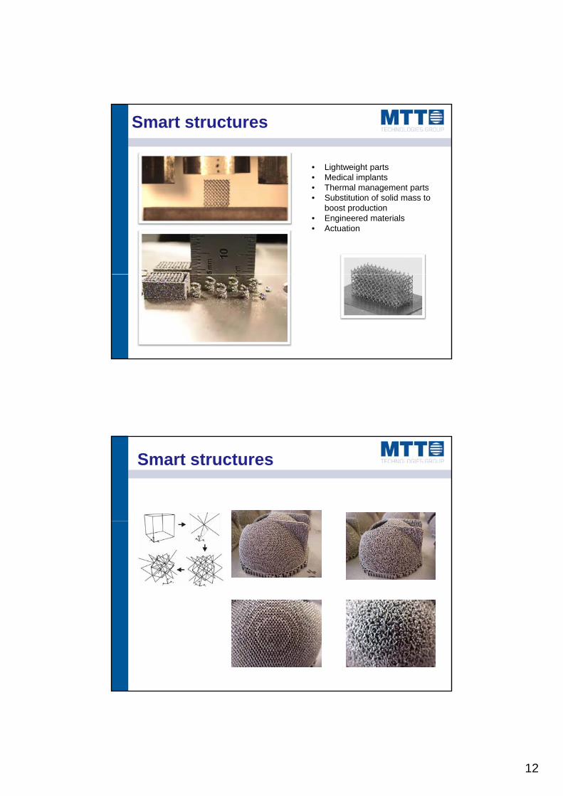
Properties of typical parts
Surfaces Strength Accuracy
Residual Stress Density Hardness
± 25µm in 100 mmTypically as good
as parentRz 30 µm
up to 54 HRCup to 99.9 %Preheated powder

6
Typical parts
Ti Al6 V4 Inconel 625
Al Si12 Mg1.4404
Typical uses
Heat sinks have beenHeat sinks have been designed and tested for avionics cooling

7
Typical uses
• Material:
• 1 2344 tool steel• 1.2344 tool steel
• Dimensions:
• 170 x 46 x 18 [mm]
• Layer thickness:
• 75 µm
• Build time:Build time:
• 48 hours
• Post treatment:
• Manual polishing
Typical uses
• Considerable reduction of cycle time
• Ideal design of size, form and function of cooling channels
• Quality improvement of injection moulding

8
Typical uses
• Mounting of four pre-fabricated cores on buildingfabricated cores on building platform
• Precise individual positioning of layer data to mounted cores
• Economic hybrid manufacturing
Interface between Rapid• Interface between Rapid Manufacturing / Conventional Tooling
Typical uses
• Up to 80 parts can be produced• Up to 80 parts can be produced in one run
• Customised parts can be produced
• Very good surface finish in many materials including CoCr, CoCrMb, CpTi, Ti6Al4V and Ti6 Al4NbAl4Nb
• Noble metals can be produced
• Low cost equipment is entering the market

9
Trabecular lower jaw implant Dense skull plate
Not so typical uses
P ti t ifi t i• Patient specific geometries
• Specialist alloysTiAl6Nb7 in this case
• Incorporation of surgical fixtures
• Structured bone integration surfaces
• Bone-Implant modulus matching
Source: Royal Perth Hospital, Australia
Not so typical uses
• Following a severe climbing accident th ti t i THR hi hthe patient was given a THR which was revised a number of times until further revision was impossible
• 3D X-ray and computer tomography allowed analysis of existing patient bone
• Models were made of the geometry

10
Source: Royal Perth Hospital, Australia
Customised SLM implants
• Cage designed to fit bone and give proper screw placement
• Results :minimum removal of healthy bone structure and reduction of operation time
Source: Royal Perth Hospital, Australia • Analysis of 3d data set, automatical generation of support structures
Customised SLM implants
pp
• SLM building of the cage
• with 0.05 mm thin layers (TiAl6Nb7 or TiAl6V4)
• Finish of the cage
• (removal of supports)
• SLM + Finish < 2 days
• Courier cage to Perth

11
Source: Royal Perth Hospital, Australia
Customised SLM implants
• Analysis and sterilisation of built prostheses
• Preparation of the patient
• No fitting required during operation due to custom cage
• Insertion and screwing of the cage made of TiAl6Nb7g
• Operation time reduced to 2 h compared to 3 h with standard prostheses
• density gain by improved melting
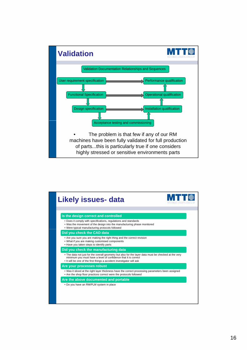
Smart structures
Density gain by improved melting strategy, D>99,8%
Helium leakage test fulfilled up to 6x10⁻¹⁰ mbar
UHV compatible!
2 mm
strategy, D>99.9%
• helium leak test fulfilled up to 6x10⁻¹⁰ mbar
• UHV compatibleUHV compatible!
Material: 1.2344 tool steel
• simultaneous growth of dense and porous regions
12
Smart structures
• Lightweight parts• Medical implants• Thermal management partsThermal management parts• Substitution of solid mass to
boost production• Engineered materials• Actuation
SOME EXAMPLESSmart structures

13
Material name Material type Typical applications
Stainless Steel 1.4404 (316L) t i l t l
functional prototypes
Current materials
stainless steel
Tool Steel 1.2344 (H13) tool steel
Injection moulding tooling; functional prototypes
CpTi Commercially Pure Titanium
Implants and medical devices
Ti64 Ti6Al4V Implants and high performance functional components
Ti6Al7Nb Ti6Al7Nb Implantable devices
Aluminium Aluminum Silicon Alloy
Functional prototypes and series parts;
Cobalt Chrome CoCrMo superalloy
Functional prototypes and series parts; medical, dental
Previous equipment
SLM 100
• Build volume:
Ø• 125 mm Ø x 70 mm
• Layer thickness:
• 20 µm – 50 µm
• Fiber Laser 50 W or 100 W
• Spot size: 30– 100 µmSpot size: 30 100 µm
• Build speed: up to 70 tooth caps per shift

14
Previous equipment
• Build volume 250 x 250 x 210mm
• Build speed: 5 cm3 –30 cm3 per h
• Layer thickness: 30 µm – 100 µm
• Fiber Laser:100 W –400 W cw400 W, cw
• Laser spot size: 80 µm – 250 µm
Future equipment?
• Custom build volumes
• Thinner layer thickness 10 µm – 100 µm
• Higher laser power 100 W – 1kW W, cw
Current equipment
Higher laser power 100 W 1kW W, cw
• Smaller spot size 50 µm – 2500 µm
• Smater materials delivery
• Better build atmospheres (sub 100ppm O2)
• Paletised substrates and removable build units
• Rugedised for the shop floor
• Simple controlled user interfaces
• Beam monitoring (now please)
• Powder handling
• HAZOP as standard
• Verifification as standard
• Data logging as standard

15
Future machine SLM XXXCurrent equipment
Future machine SLM XXXSo what?
16
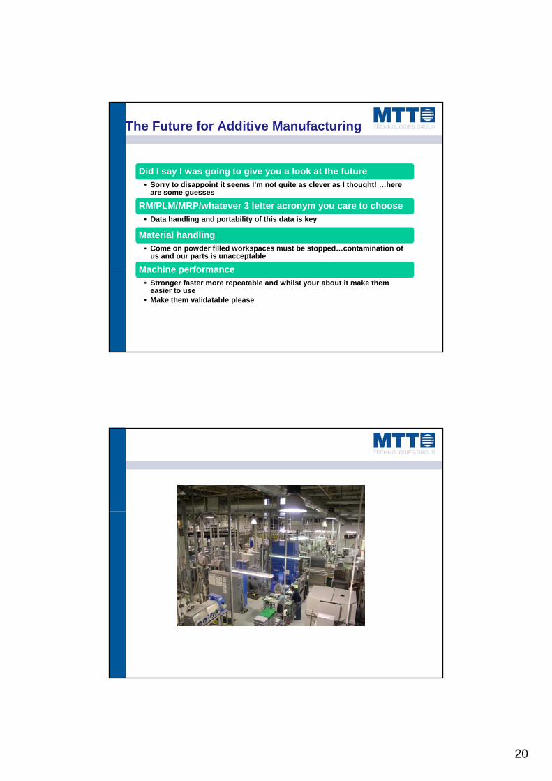
Validation
Validation Documentation Relationships and Sequences
User requirement specification Performance qualification
Functional Specification
Design specification
Operational qualification
Installation qualification
Acceptance testing and commissioning
• The problem is that few if any of our RM machines have been fully validated for full production
of parts...this is particularly true if one considers highly stressed or sensitive environments parts
Likely issues- data
Is the design correct and controlled• Does it comply with specifications, regulations and standards• Was the movement of the design into the manufacturing phase monitored• Were typical manufacturing protocols followed yp g p
Did you check the CAD data• Are you sure you are making the right thing and the correct revision• What if you are making customised components• Have you taken steps to identify parts
Did you check the manufacturing data• The data not just for the overall geometry but also for the layer data must be checked at the very
minimum you must have a level of confidence that it is correct• It will be one of the first things a accident investigator will ask
Are your processes robustAre your processes robust• Was it sliced at the right layer thickness have the correct processing parameters been assigned• Are the shop floor practices correct were the protocols followed
Are the above documented and portable• Do you have an RM/PLM system in place

17
Likely issues- machine
Material properties•Variation in material properties in the x/y/z direction is not acceptable full stop…lets not even bother having the argument I don’t care if you think you can design for it…you can’t.
Property variation on a machine•This is not acceptable the only property variation on a machine that is acceptable is random variation and this should be minimised.
Parameter variation between machines•All machines of a particular design must have the same machine parameters how else can you procreate and maintain validation.
Temporal Instability•Machines must be stable over time and they must be able to detect when they are outside limits…assuming those limits have been defined
Machine reliability•Will your machine stand up to production•Will it do its job day in day out for 10 plus years
Is the user interface simple enough•I want to drag someone in off the streets and get them to press go I do not want to employ PhD’s to work in my factory
Collection and storage of manufacturing data•Is the manufacturing data logged•Is it stored (75 years!)
Some Examples
The tensile strengths of samples are shown across 4 builds you can see the same characteristics on each build. It is clear this is NOT a random process variable…do you accept the parts…what if you part spans the whole p pbed…how do you design that out…

18
Some Examples
The compressive strength of samples are shown across 4 builds on two different machines at the same machine settings you can see one build is significantly weaker than the other. …do you accept the machines knowing full well that you will have to validate them separately
Some Examples
EVERY LAYER PLEASE…its not good enough to build test samples by each part

19
Some Examples
Thought I’d better put some stuff in on lasers
20
The Future for Additive Manufacturing
Did I say I was going to give you a look at the future• Sorry to disappoint it seems I’m not quite as clever as I thought! hereSorry to disappoint it seems I m not quite as clever as I thought! …here
are some guesses
RM/PLM/MRP/whatever 3 letter acronym you care to choose• Data handling and portability of this data is key
Material handling• Come on powder filled workspaces must be stopped…contamination of
us and our parts is unacceptable
Machine performanceMachine performance• Stronger faster more repeatable and whilst your about it make them
easier to use• Make them validatable please
Can we do it now?

21
THANKS FOR LISTENING
I was going to write someI was going to write some conclusions but to be honneset I guessed either you’d have seen enough of me by now or I’d have run out of time.
If you need any further information contact me on.