self-aligning tow bar - demco products
TRANSCRIPT

TB20060, Rev 304/20
SELF-ALIGNING TOW BARCommander 2

Page 2 TB20060
WARNING: Exceeding weight limitations or not using a towing vehicle larger and at least 500 lbs. heavier than the tow bar and the towed vehicle combined can result in loss of towing vehicle control, separation of the tow bar from the tow-ing vehicle, or separation of the towed vehicle from the tow bar, causing severe personal injury, death, and/or property damage.
Warranty Policy, Operator Manuals & RegistrationGo online to www.demco-products.com to review Demco warranty policies, operator manuals and register your Demco product.
Introduction
TABLE OF CONTENTSWarranty Policy, Operator Manuals & Registration .................................................................................................................... 2Equipment Safety Guidelines ....................................................................................................................................................... 3Remember ....................................................................................................................................................................................... 3Lighting and Marking ..................................................................................................................................................................... 3Safety Information .......................................................................................................................................................................... 3SAFETY Sign Locations .................................................................................................................................................................. 4Safety Sign Care .............................................................................................................................................................................. 4Before operation ............................................................................................................................................................................. 4During Operation ........................................................................................................................................................................... 5Highway and Transport Operations ............................................................................................................................................. 5Following Operation ...................................................................................................................................................................... 5Performing Maintenance ............................................................................................................................................................... 6Bolt Torque Data for Standard Nuts, Bolts, and Capscrews ...................................................................................................... 7Important Notice! ........................................................................................................................................................................... 8Latch Disassembly ......................................................................................................................................................................... 9Latch Reassembly ........................................................................................................................................................................... 9Hooking Up Tow Bar to Vehicle to Be Towed ........................................................................................................................... 10Unhooking the Towed Vehicle .................................................................................................................................................... 11Receiver Parts Brteakdown .......................................................................................................................................................... 12Pivot Head Parts Brteakdown ...................................................................................................................................................... 12Connecting Leg Parts Breakdown .............................................................................................................................................. 13Connecting Legs to Pivot Head Parts Breakdown .................................................................................................................... 14Saftey Cables ................................................................................................................................................................................. 15Safety Cable Extensions .............................................................................................................................................................. 154” or 6” Drop/Lift Receiver Hitch ................................................................................................................................................ 16Auxiliary Lighting Cable .............................................................................................................................................................. 163-Piece Locking Pins .................................................................................................................................................................... 17Tow Bar to Base PLate Locking Pins ........................................................................................................................................... 17Light Bar ......................................................................................................................................................................................... 18

TB20060 Page 3
SAFETYTAKE NOTE! THIS SAFETY ALERT SYMBOL FOUND THROUGHOUT THIS MANUAL IS USED TO CALL YOUR ATTENTION TO INSTRUCTIONS INVOLVING YOUR PERSONAL SAFETY AND SAFETY OF OTHERS. FAILURE TO FOLLOW THESE INSTRUCTIONS CAN RESULT IN INJURY OR DEATH.
Note use of following signal words DANGER, WARNING, and CAUTION with safety messages. Appropriate signal word for each has been selected using following guidelines:
DANGER: Indicates an imminently hazardous situation that, if not avoided, will result in serious injury or death. This signal word is to be limited to the most extreme situations typically for tow bar components which, for functional purposes, cannot be guarded.
WARNING: Indicates a potentially hazardous situation that, if not avoided, could result in serious injury or death, and includes hazards that are exposed when guards are removed. It may also be used to alert against unsafe practices.
CAUTION: Indicates a potentially hazardous situation that, if not avoided, may result in minor or moderate injury. It may also be used to alert against unsafe practices.
If you have questions not answered in this manual, or require additional copies, please contact your dealer or Demco, 4010 320th Street, Boyden, IA 51234, ph: (712) 725-2311 or (712) 725-2302, Toll Free: 1-800-543-3626 Fax: (712) 725-2380, http://www.demco-products.com
THIS SYMBOL MEANSATTENTION
BECOME ALERTYOUR SAFETY IS INVOLVED!
Every year many accidents occur which could have been avoided by a few seconds of thought and a more careful approach to handling equipment. You, the operator, can avoid many accidents by observing and following precautions in this section. To avoid personal injury, study following precautions and insist those working with you, or you yourself, follow them.
Replace any caution, warning, danger or instruction safety decal that is not readable or is missing. Location of such decals is indicated in this booklet.
Do not attempt to operate this tow bar under the influence of alcohol or drugs.
Review safety instructions with all users. Operator should be a responsible adult. DO NOT ALLOW PERSONS TO OPERATE OR ASSEMBLE THIS TOW BAR UNTIL THEY HAVE DEVELOPED A THOROUGH UNDERSTANDING OF SAFETY PRECAUTIONS AND HOW IT WORKS.
Do not paint over, remove, or deface any safety signs or warning decals on your tow bar. Observe all safety signs and practice instructions on them.
Never exceed limits of a tow bar. If its ability to do a job safely is in question DON’T TRY IT.
SAFETY...You can live with it
It is the responsibility of owner to know lighting and marking requirements of local highway authorities and to install and main-tain equipment to provide compliance with regulations. Light bar kits are available from your dealer or from manufacturer.
Your best assurance against accidents is a careful and responsible operator. If there is any portion of this manual or function you do not understand, contact your local authorized dealer or manufacturer.
Safety Information
Lighting and Marking
Remember
Equipment Safety Guidelines
Signal Words

Page 4 TB20060
Safety Sign Care• Keep safety signs clean and legible at all times.
• Replace safety signs that are missing or have become illegible.
• Replacement parts that displayed a safety sign should also display current sign.
• Safety signs are available from your distributor, dealer parts department, or factory.
How to install safety signs:
• Be sure installation surface is clean and dry.
• Decide on exact position before you remove backing paper.
• Remove smallest portion of split backing paper.
• Align decal over specified area and carefully press small portion with exposed sticky backing in place.
• Slowly peel back remaining paper and carefully smooth remaining portion of decal into place.
• Small air pockets can be pierced with a pin and smoothed out using piece of decal backing paper.
• Carefully study and understand this manual.
• Give tow bar a visual inspection for any loose bolts, worn parts, or cracked welds, and make necessary repairs. Follow mainte-nance safety instructions included in this manual.
• Be sure there are no tools lying on tow bar, towing unit or towed vehicle.
• Do not use tow bar until you are sure that area is clear, especially around children and animals.
• Don’t hurry learning process or take tow bar for granted. Ease into it and become familiar with your new tow unit.
• Practice operation of your tow unit and its attachments. Completely familiarize yourself and other operators with its operation before using.
• Securely attach to towing unit. Use an appropriately sized and rated hitch ball and/or a class III, class IV receiver and attach safety cables.
• Criss cross safety cables under tow bar, secure to mounting loops on towing vehicle.
• Do not allow anyone to stand between vehicles when backing up.
• Make sure tow rating on towing unit is high enough for what it is towing.
• To prevent swaying of towed vehicle insure all tires are inflated to specifications. Failure to inflate tires evenly will result in towed vehicle to pull unevenly.
Before operation
SAFETY Sign LocationsTypes of safety sign and locations on the Commander 2 are shown in illustration below. Good safe-ty requires that you familiarize yourself with various safety signs, type of warning, and particular function related to that area, that requires your SAFETY AWARENESS.
WARNING
CAUTION
Safety Information

TB20060 Page 5
During Operation• Always follow state and local regulations regarding auxiliary lighting when towing. Be sure to check with local law enforcement
agencies for your own particular regulations. Only safety cables (not elastic or nylon/plastic tow straps) should be used to retain connection between towing unit and towed vehicle in event of separation.
• Do not load towed vehicle with cargo. Towed vehicles exceeding weight limits will overload tow bar and may cause serious injury and damage.
• Beware of bystanders, PARTICULARLY CHILDREN! Always look around to make sure it is safe to start engine of towing unit and mov-ing towed vehicle. This is particularly important with higher noise levels, as you may not hear people shouting.
• NO PASSENGERS ALLOWED- Do not carry passengers anywhere on or in towed vehicle.
• When halting operation, even periodically, set towing unit’s parking brake, shut off engine, and remove ignition key.
• Be extra careful on inclines.
• MANEUVER TOWING UNIT AT SAFE SPEEDS.
• Avoid overhead wires or other obstacles. Contact with overhead lines could cause serious injury or death.
• Avoid loose gravel, rocks, and holes; they can be dangerous for unit operation or movement.
• Allow for unit length when making turns.
• Do not work under raised components or attachments unless securely positioned and blocked.
• Keep all bystanders and pets clear of work area.
• Operate towing unit from operators seat only.
• As a precaution, recheck hardware on tow bar every 200 miles, and correct all problems. Follow maintenance safety proce-dures.
Following Operation• Following operation, or when unhooking, stop towing vehicle, set parking brake, shut off engine and remove ignition key.
• Store tow bar in area away from human activity.
• Do not permit children to play on or around stored tow bar.
• Make sure parked vehicle is on hard, level surface.
• Wheel chocks may be needed to prevent vehicle from rolling.
Highway and Transport Operations• Adopt safe driving practices:
- Always drive at safe speed relative to local conditions and ensure that your speed is low enough for an emergency stop.
- Reduce speed prior to turns to avoid risk of overturning.
- Always keep towing unit in gear to provide engine braking when going downhill. Do not coast.
- Do not drink and drive!
• Comply with state and local laws governing highway safety.
• Local laws should be checked for all highway lighting and marking requirements.
• Plan your route to avoid heavy traffic.
• Be a safe and courteous driver. Always yield to oncoming traffic in all situations, including narrow bridges, intersections, etc.
• Watch for obstructions overhead and to both sides while towing vehicle.
• Operate with maximum visibility at all times. Make allowances for increased length and weight when making turns and stopping.
Safety Information

Page 6 TB20060
• Good maintenance is your responsibility. Poor maintenance is an invitation to trouble.
• Make sure there is plenty of ventilation. Never operate engine of towing unit in a closed building. Exhaust fumes may cause asphyxiation.
• Before working on tow bar, stop towing vehicle, set parking brake, turn off engine and remove ignition key.
• Always use proper tools or equipment for job at hand.
• Use extreme caution when making adjustments.
• Follow torque chart in this manual when tightening bolts and nuts.
• After servicing, be sure all tools, parts and service equipment are removed.
• Do not allow grease or oil to build up.
• When replacing bolts, refer to owners manual.
• Refer to bolt torque chart for head identification marking.
• Where replacement parts are necessary for periodic maintenance and servicing, genuine factory replacement parts must be used to restore your tow unit to original specifications. Manufacturer will not claim responsibility for use of unapproved parts and/or accessories or other damages as a result of their use.
• If tow unit has been altered in any way from original design, manufacturer does not accept any liability for injury or warranty.
• A fire extinguisher and first aid kit should be kept readily accessible while performing maintenance on this tow bar.
• Any disassembly of the Commander 2 must be performed by an authorized dealer or sent back to Demco for repair and main-tenance.
Performing Maintenance
Safety Information

TB20060 Page 7
Bolt Torque for Metric bolts *
CLASS 8.8 CLASS 9.8 CLASS 10.9 “A” lb-ft (N.m) lb-ft (N.m) lb-ft (N.m) 6 9 (13) 10 (14) 13 (17) 7 15 (21) 18 (24) 21 (29) 8 23 (31) 25 (34) 31 (42) 10 45 (61) 50 (68) 61 (83) 12 78 (106) 88 (118) 106 (144) 14 125 (169) 140 (189) 170 (230) 16 194 (263) 216 (293) 263 (357) 18 268 (363) -- -- 364 (493) 20 378 (513) -- -- 515 (689) 22 516 (699) -- -- 702 (952) 24 654 (886) -- -- 890 (1206)
Bolt Torque Data for Standard Nuts, Bolts, and CapscrewsTighten all bolts to torques specified in chart unless otherwise noted. Check tightness of bolts periodically, using bolt chart as guide. Replace hardware with same grade bolt.
NOTE: Unless otherwise specified, high-strength Grade 5 hex bolts are used throughout assembly of equipment.
Torque figures indicated are valid for non-greased or non-oiled threads and heads unless otherwise specified. Therefore, do not grease or oil bolts or capscrews unless otherwise specified in this manual. When using locking elements, increase torque values by 5%.
* GRADE or CLASS value for bolts and capscrews are identified by their head markings.
GRADE 2 GRADE 5 GRADE 8 “A” lb-ft (N.m) lb-ft (N.m) lb-ft (N.m)1/4” 6 (8) 9 (12) 12 (16)5/16” 10 (13) 18 (25) 25 (35)3/8” 20 (27) 30 (40) 45 (60)7/16” 30 (40) 50 (70) 80 (110)1/2” 45 (60) 75 (100) 115 (155)9/16” 70 (95) 115 (155) 165 (220)5/8” 95 (130) 150 (200) 225 (300)3/4” 165 (225) 290 (390) 400 (540)7/8” 170 (230) 420 (570) 650 (880)1” 225 (300) 630 (850) 970 (1310)
Torque all 1/4” button head screws to 6 ft/lbs and apply Blue RR to threads.
GRADE-2 CLASS 8.8 CLASS 10.9GRADE-5 GRADE-8 CLASS 9.8
8.8 9.8 10.9A
Bolt Torque
Bolt Torque for Standard bolts *
Page 8 TB20060
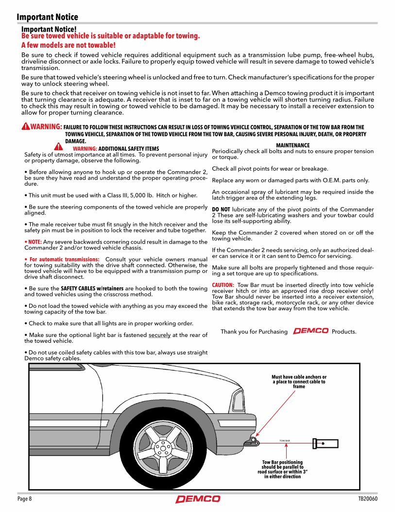
Important Notice!Be sure towed vehicle is suitable or adaptable for towing. A few models are not towable!Be sure to check if towed vehicle requires additional equipment such as a transmission lube pump, free-wheel hubs, driveline disconnect or axle locks. Failure to properly equip towed vehicle will result in severe damage to towed vehicle’s transmission. Be sure that towed vehicle’s steering wheel is unlocked and free to turn. Check manufacturer’s specifications for the proper way to unlock steering wheel.Be sure to check that receiver on towing vehicle is not inset to far. When attaching a Demco towing product it is important that turning clearance is adequate. A receiver that is inset to far on a towing vehicle will shorten turning radius. Failure to check this may result in towing or towed vehicle to be damaged. It may be necessary to install a receiver extension to allow for proper turning clearance.
WARNING: ADDITIONAL SAFETY ITEMSSafety is of utmost importance at all times. To prevent personal injury or property damage, observe the following.
• Before allowing anyone to hook up or operate the Commander 2, be sure they have read and understand the proper operating proce-dure.
• This unit must be used with a Class III, 5,000 lb. Hitch or higher.
• Be sure the steering components of the towed vehicle are properly aligned.
• The male receiver tube must fit snugly in the hitch receiver and the safety pin must be in position to lock the receiver and tube together.
• NOTE: Any severe backwards cornering could result in damage to the Commander 2
and/or towed vehicle chassis.
• For automatic transmissions: Consult your vehicle owners manual for towing suitability with the drive shaft connected. Otherwise, the towed vehicle will have to be equipped with a transmission pump or drive shaft disconnect.
• Be sure the SAFETY CABLES w/retainers are hooked to both the towing and towed vehicles using the crisscross method.
• Do not load the towed vehicle with anything as you may exceed the towing capacity of the tow bar.
• Check to make sure that all lights are in proper working order.
• Make sure the optional light bar is fastened securely at the rear of the towed vehicle.
• Do not use coiled safety cables with this tow bar, always use straight Demco safety cables.
WARNING: FAILURE TO FOLLOW THESE INSTRUCTIONS CAN RESULT IN LOSS OF TOWING VEHICLE CONTROL, SEPARATION OF THE TOW BAR FROM THE TOWING VEHICLE, SEPARATION OF THE TOWED VEHICLE FROM THE TOW BAR, CAUSING SEVERE PERSONAL INJURY, DEATH, OR PROPERTY DAMAGE.
MAINTENANCEPeriodically check all bolts and nuts to ensure proper tension or torque.
Check all pivot points for wear or breakage.
Replace any worn or damaged parts with O.E.M. parts only.
An occasional spray of lubricant may be required inside the latch trigger area of the extending legs.
DO NOT lubricate any of the pivot points of the Commander 2 These are self-lubricating washers and your towbar could lose its self-supporting ability.
Keep the Commander 2 covered when stored on or off the towing vehicle.
If the Commander 2 needs servicing, only an authorized deal-er can service it or it can sent to Demco for servicing.
Make sure all bolts are properly tightened and those requir-ing a set torque are up to specifications.
CAUTION: Tow Bar must be inserted directly into tow vehicle receiver hitch or into an approved rise drop receiver only! Tow Bar should never be inserted into a receiver extension, bike rack, storage rack, motorcycle rack, or any other device that extends the tow bar away from the tow vehicle.
Thank you for Purchasing Products.
Tow Bar positioningshould be parallel to
road surface or within 3” in either direction
Must have cable anchors or a place to connect cable to
frame
TOW BAR
Important Notice
TB20060 Page 9
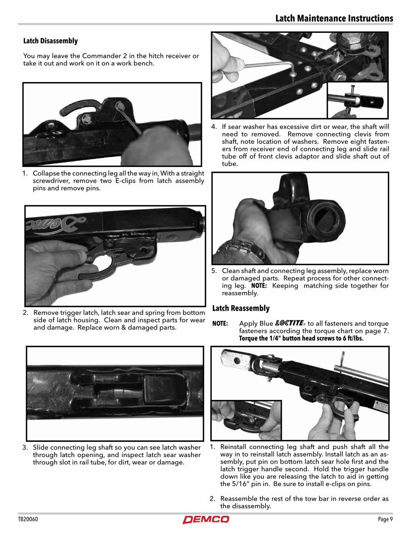
Latch Disassembly
You may leave the Commander 2 in the hitch receiver or take it out and work on it on a work bench.
Latch Reassembly
NOTE: Apply Blue RR to all fasteners and torque fasteners according the torque chart on page 7. Torque the 1/4” button head screws to 6 ft/lbs.
1. Collapse the connecting leg all the way in, With a straight screwdriver, remove two E-clips from latch assembly pins and remove pins.
3. Slide connecting leg shaft so you can see latch washer through latch opening, and inspect latch sear washer through slot in rail tube, for dirt, wear or damage.
5. Clean shaft and connecting leg assembly, replace worn or damaged parts. Repeat process for other connect-ing leg. NOTE: Keeping matching side together for reassembly.
1. Reinstall connecting leg shaft and push shaft all the way in to reinstall latch assembly. Install latch as an as-sembly, put pin on bottom latch sear hole first and the latch trigger handle second. Hold the trigger handle down like you are releasing the latch to aid in getting the 5/16” pin in. Be sure to install e-clips on pins.
2. Reassemble the rest of the tow bar in reverse order as the disassembly.
4. If sear washer has excessive dirt or wear, the shaft will need to removed. Remove connecting clevis from shaft, note location of washers. Remove eight fasten-ers from receiver end of connecting leg and slide rail tube off of front clevis adaptor and slide shaft out of tube.
2. Remove trigger latch, latch sear and spring from bottom side of latch housing. Clean and inspect parts for wear and damage. Replace worn & damaged parts.
Latch Maintenance Instructions

Page 10 TB20060
Step 5. Slide and twist the legs into position to attach them to the baseplate on towed vehicle. Secure to baseplate using the two attaching pins and 1/4” quick-lock pin. Attach safety cables (see below). Now connect the lighting cable between the tow-ing vehicle and the towed vehicle lighting system or optional light bar. The coiled section of the cable will be stored on the support rod. Towing vehicle must be larger and at least 500 lbs. heavier than the towed vehicle and tow bar combined.
Step 1. Out of the box, the Commander 2 tow bar is setup with the safety cables installed, ready for you to tow. Install the light cable (optional) by placing the coil over the wire support rod. Secure the cable with the cable locking hair pin.
Hooking Up Tow Bar to Vehicle to Be TowedRefer to load limits on inside of front cover.
Step 4. Position the vehicle to be towed approx. 24” behind the towing vehicle. Perform a tow bar check, look for any loose fasteners, condition of safety cables, excessive movement in connecting leg shaft when the shaft is extended and locked. If any excessive movement or loose fasteners, the tow bar will need to be serviced before towing. The vehicles do not have to be in straight alignment to complete the hook-up. Engage towed vehicle and towing vehicle parking brake.
Quick-Lock pin must beclosed properly. Fold ring of Quick-Lock Pin to the side of the pin that allows ring to snap against pin. If you have folded its ring the wrong way it will not snap against pin.
Step 2. Insert the Commander 2 into a Class III or IV hitch. CAUTION: Tow bar must be inserted directly into tow vehicle receiver hitch or into an approved rise drop receiver only! Tow bar should never be inserted into a receive extension, bike rack, storage rack, motorcycle rack, or any other device that extends the tow bar away from the tow vehicle.
Step 3. Insert receiver pin through receiver until pin passes through. Secure pin with the Receiver hair pin. Crisscross safety cables underneath pivot assembly and attach to chain anchors on towing vehicle. Do not use coiled safety cables with this tow bar, always use straight Demco safety cables.
Step 6. Hook safety cables to chain anchor of baseplate.Note: Make sure safety clip is in working order.
Step 7. Leave the electrical cable storage pin (circled above) out for the locking procedure in step 6. When step 6 is completed, position cable on storage rod leaving enough slack, and insert pin.
Tow Bar Instructions

TB20060 Page 11
Unhooking the Towed Vehicle
Step 1. Begin unhooking your unit by first applying both vehicle parking brakes and unhook your lighting and safety cables. Failure to have parking brakes applied could allow towed vehicle to roll forward. This could result in limited space between towing vehicle and towed ve-hicle.
Step 3. Remove pins that attach tow bar to towed vehicle. Commander 2 will remain in position. Slide the extendable legs back into tube. Position electrical cable on storage rod and in-sert pin to prevent cable from sliding off.
Step 4. Now take the bottom leg and lift up high enough for storage pin to clear under storage plate. Turn leg under storage and push leg down so pin locks into plate. Repeat for top leg.
Step 8. Once you are secured to the tow bar, release towed vehicle parking brake, and slowly back up the towed vehicle straight back until one leg latches. Determine which leg latched by having an assistant tell you. If you are by yourself put towed vehicle in neutral or park, and apply parking brake. Get out and check to see which leg latched. To latch the second leg, turn the top of towed vehicle’s steering wheel into the direction of the leg that first latched, and slowly back up again. This will latch the second leg. Once both legs are latched, straighten wheels on towed vehicle, shut vehicle off. Adjust tow bar receiver head so the vertical bolt is perpendicular to the baseplate height of towed vehicle. Tighten the 1/2” bolts on each side of joint head to 85 ft/lbs. If manual transmission, shift to neutral, unlock steering wheel and make sure parking brake is released. Note: For four wheel drive units, shift transfer case into neutral also. Reminder: Consult vehicle’s manufacturer for towing suitability of manual or automatic trans-mission vehicles.
Step 2. Use the latch trigger handle to release the connect-ing legs between the two vehicles by pressing down on the latch trigger handle.
NOTE: Your Commander 2 can store in three storage positions, both arms left, both arms right and one arm left and one arm right.
NOTE: The Commander 2 comes with a 1-1/2” off-set receiver that can be flipped to help level the tow bar with the towed ve-hicle. The receiver is in the down position from factory, to change to the higher position, remove both 1/2” bolts and washer from side of receiver joint head. Remove the 3/4” nut and bolt, slide receiver out of receiver joint head and flip receiver into the up po-sition. Slide receiver back into the receiver joint head and reinstall the fasteners.
Up Position Down Position
Tow Bar Instructions
Page 12 TB20060
4
7
21
8
3
6
95
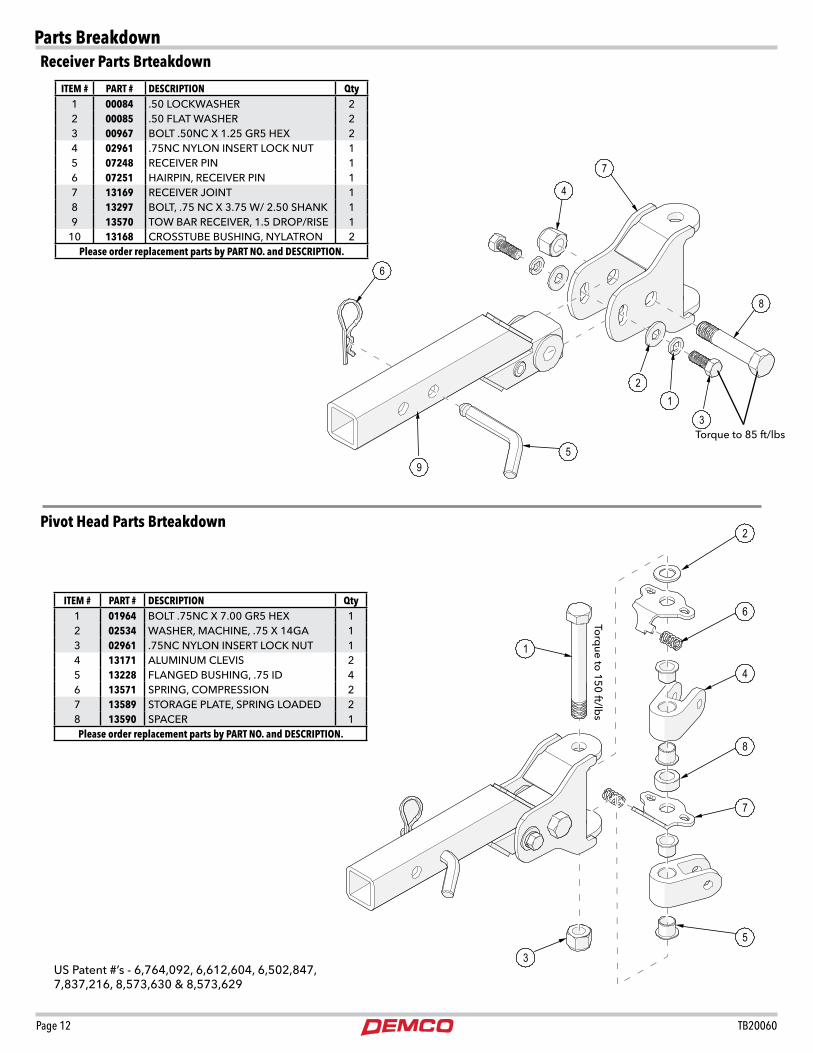
US Patent #’s - 6,764,092, 6,612,604, 6,502,847, 7,837,216, 8,573,630 & 8,573,629
Torque to 85 ft/lbs
Parts Breakdown
2
8
6
5
7
3
4
1
ITEM # PART # DESCRIPTION Qty1 00084 .50 LOCKWASHER 22 00085 .50 FLAT WASHER 23 00967 BOLT .50NC X 1.25 GR5 HEX 24 02961 .75NC NYLON INSERT LOCK NUT 15 07248 RECEIVER PIN 16 07251 HAIRPIN, RECEIVER PIN 17 13169 RECEIVER JOINT 18 13297 BOLT, .75 NC X 3.75 W/ 2.50 SHANK 19 13570 TOW BAR RECEIVER, 1.5 DROP/RISE 1
10 13168 CROSSTUBE BUSHING, NYLATRON 2Please order replacement parts by PART NO. and DESCRIPTION.
ITEM # PART # DESCRIPTION Qty1 01964 BOLT .75NC X 7.00 GR5 HEX 12 02534 WASHER, MACHINE, .75 X 14GA 13 02961 .75NC NYLON INSERT LOCK NUT 14 13171 ALUMINUM CLEVIS 25 13228 FLANGED BUSHING, .75 ID 46 13571 SPRING, COMPRESSION 27 13589 STORAGE PLATE, SPRING LOADED 28 13590 SPACER 1Please order replacement parts by PART NO. and DESCRIPTION.
Torq
ue to 150 ft/lb
s
Receiver Parts Brteakdown
Pivot Head Parts Brteakdown

TB20060 Page 13
19
1
15
617
2
13
3
21
59
12
188
16
20
107
4
22
14
11 PART # Qty DESCRIPTIONTB21041 2 Commander 2 DecalTB21038 1 User Instruction DecalTB21042 1 Warning Do Not Exceed Weight Limits &
Manufacturers Patent / Hitch Rating Decal
Please order replacement parts by PART NO. and DESCRIPTION.
DECALS
Before Towing, perform a tow bar safety check, look for any loose fasteners, condition of safety cables, excessive movement in connecting leg shaft when the shaft is extended and locked. If any excessive movement or loose fasteners are found, the tow bar will need to be serviced before towing. If tow bar needs servicing, please bring it to an au-thorized dealer or send it to Demco.
Parts Breakdown
ITEM # PART # DESCRIPTION Qty1 00182 HAIR PIN, .120 WIRE X 2.375 12 02397 LYNCH PIN 23 02592 NUT, .375NC NYLON LOCK 24 03805 WIRE SUPPORT ROD 15 03809 CLEVIS SPACER WASHER 46 03878 ATTACHING PIN 27 07223 ROLL PIN, .156 X .75 18 13176 TRIGGER HANDLE 29 13179 COMPRESSION SPRING 2
10 13185 SCREW, SOCKET BUTTON, .25 -20 X .50 SS 1611 13227 PLASTIC BUSHING, .50 ID X .75 LG 212 13249 CLEVIS GROOVED PIN, .313 X 1.25, SS 413 13250 RETAINING RING F/ .313 SHAFT 414 13431 STORAGE PIN 215 13432 RETAINING E-CLIP, SS F/ .25 SHAFT 216 13572 CLEVIS BOLT, .375 NC X 2.25 LG, 1.50 SHANK 217 13582 CONNECTING CLEVIS F/Commander 2 218 13859 LATCH SEAR 219 15713 CONNECTING SHAFT, Commander 2 220 16699 CONNECTING LEG TUBE, LEFT 121 16700 CONNECTING LEG TUBE, RIGHT 122 16701 FRONT ADAPTOR 2
Please order replacement parts by PART NO. and DESCRIPTION.
Connecting Leg Parts Breakdown
Page 14 TB20060
2
3
5
61
4
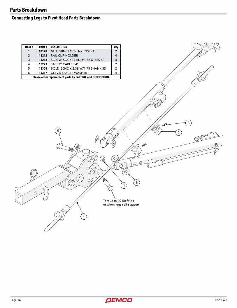
Torque to 40-50 ft/lbsor when legs self-support
ITEM # PART # DESCRIPTION Qty1 02178 NUT, .50NC LOCK, NY. INSERT 22 13212 RAIL CLIP HOLDER 43 13213 SCREW, SOCKET HD, #8-32 X .625 SS 44 13273 SAFETY CABLE 54” 25 13305 BOLT, .50NC X 2.38 W/1.75 SHANK SS 26 13317 CLEVIS SPACER WASHER 4
Please order replacement parts by PART NO. and DESCRIPTION.
Connecting Legs to Pivot Head Parts Breakdown
Parts Breakdown

TB20060 Page 15
1
1
2
1ITEM # PART # DESCRIPTION Qty
9523051 54”Safety Cable Kit (complete)9523055 64”Safety Cable Kit (complete) Optional
1. 13273 Straight Safety Cable w/Hooks 54” 21. 13507 Straight Safety Cable w/Hooks 64” 2
Please order replacement parts by PART NO. and DESCRIPTION.
ITEM # PART # DESCRIPTION Qty
9523064 12”Safety Cable Extension Kit
9523065 18”Safety Cable Extension Kit
1. 13779 Safety Cable Extension12” 2
2. 13780 Safety Cable Extension 18” 2
Please order replacement parts by PART NO. and DESCRIPTION.
Tow Bar Options
Saftey Cables
Safety Cable Extensions
Page 16 TB20060
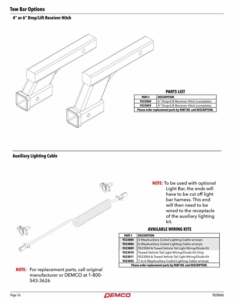
PART # DESCRIPTION9523060 6” Drop/Lift Receiver Hitch (complete)9523059 4” Drop/Lift Receiver Hitch (complete)
Please order replacement parts by PART NO. and DESCRIPTION.
PARTS LIST
PART # DESCRIPTION9523004 4-WayAuxiliary Coiled Lighting Cable w/recpt.9523006 6-WayAuxiliary Coiled Lighting Cable w/recpt.9523009 9523004 & Towed Vehicle Tail Light Wiring/Diode Kit9523010 Towed Vehicle Tail Light Wiring/Diode Kit Only9523011 9523006 & Towed Vehicle Tail Light Wiring/Diode Kit9523054 7 to 6-WayAuxiliary Coiled Lighting Cable w/recpt.
Please order replacement parts by PART NO. and DESCRIPTION.
AVAILABLE WIRING KITS
NOTE: For replacement parts, call original manufacturer or DEMCO at 1-800-543-3626
NOTE: To be used with optional Light Bar, the ends will have to be cut off light bar harness. This end will then need to be wired to the receptacle of the auxiliary lighting kit.
Tow Bar Options
4” or 6” Drop/Lift Receiver Hitch
Auxiliary Lighting Cable

TB20060 Page 17
ITEM # PART # DESCRIPTION9523067 Tow-Bar to Base Plate Locking Pin Set
1. 14054 Tow-Bar to Base Plate Single Locking Pin AssemblyPlease order replacement parts by PART NO. and DESCRIPTION.
PARTS LIST
1
ITEM # PART # DESCRIPTION9523068 3-Piece Locking Pin Set
1. 14054 Tow-Bar to Base Plate Single Locking Pin Assembly2. 14047 Tow-Bar to Motor Home receiver Locking Pin
Please order replacement parts by PART NO. and DESCRIPTION.
2
1
Tow Bar Options
Tow Bar to Classic Base PLate Locking Pins
PARTS LIST
Page 18 TB20060
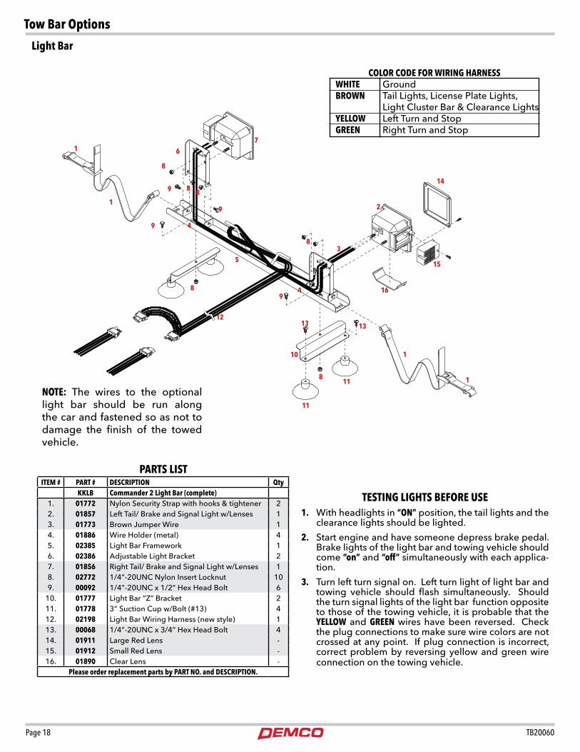
ITEM # PART # DESCRIPTION QtyKKLB Commander 2 Light Bar (complete)
1. 01772 Nylon Security Strap with hooks & tightener 22. 01857 Left Tail/ Brake and Signal Light w/Lenses 13. 01773 Brown Jumper Wire 14. 01886 Wire Holder (metal) 45. 02385 Light Bar Framework 16. 02386 Adjustable Light Bracket 27. 01856 Right Tail/ Brake and Signal Light w/Lenses 18. 02772 1/4”-20UNC Nylon Insert Locknut 109. 00092 1/4”-20UNC x 1/2” Hex Head Bolt 6
10. 01777 Light Bar “Z” Bracket 211. 01778 3” Suction Cup w/Bolt (#13) 412. 02198 Light Bar Wiring Harness (new style) 113. 00068 1/4”-20UNC x 3/4” Hex Head Bolt 414. 01911 Large Red Lens -15. 01912 Small Red Lens -16. 01890 Clear Lens -
Please order replacement parts by PART NO. and DESCRIPTION.
TESTING LIGHTS BEFORE USE1. With headlights in “ON” position, the tail lights and the
clearance lights should be lighted.
2. Start engine and have someone depress brake pedal. Brake lights of the light bar and towing vehicle should come “on” and “off” simultaneously with each applica-tion.
3. Turn left turn signal on. Left turn light of light bar and towing vehicle should flash simultaneously. Should the turn signal lights of the light bar function opposite to those of the towing vehicle, it is probable that the YELLOW and GREEN wires have been reversed. Check the plug connections to make sure wire colors are not crossed at any point. If plug connection is incorrect, correct problem by reversing yellow and green wire connection on the towing vehicle.
COLOR CODE FOR WIRING HARNESSWHITE GroundBROWN Tail Lights, License Plate Lights, Light Cluster Bar & Clearance LightsYELLOW Left Turn and StopGREEN Right Turn and Stop
1
12
1
1
67
8
88
9
9
9
8
1213 13
11
11
8
16
15
14
9
8
4
4
35
10
NOTE: The wires to the optional light bar should be run along the car and fastened so as not to damage the finish of the towed vehicle.
Tow Bar Options
PARTS LIST
Light Bar

TB20060 Page 19
