self-calibrating depth from refraction - osaka …it follows from snell’s law that the angle of...
TRANSCRIPT
Self-Calibrating Depth from Refraction
Zhihu Chen1, Kwan-Yee K. Wong1, Yasuyuki Matsushita2, Xiaolong Zhu1, and Miaomiao Liu1
1 Department of Computer Science, The University of Hong Kong, Hong Kong2 Microsoft Research Asia, Beijing, P.R.China
Abstract
In this paper, we introduce a novel method for depth ac-quisition based on refraction of light. A scene is capturedtwice by a fixed perspective camera, with the first imagecaptured directly by the camera and the second by placinga transparent medium between the scene and the camera. Adepth map of the scene is then recovered from the displace-ments of scene points in the images. Unlike other existingdepth from refraction methods, our method does not requirethe knowledge of the pose and refractive index of the trans-parent medium, but can recover them directly from the in-put images. We hence call our method self-calibrating depth
from refraction. Experimental results on both synthetic andreal-world data are presented, which demonstrate the effec-tiveness of the proposed method.
1. IntroductionDepth from refraction is a depth acquisition method
based on refraction of light. A scene is captured several
times by a fixed perspective camera, with the first image
captured directly by the camera and the others by placing a
transparent medium between the scene and the camera. The
depths of the scene points are then recovered from their dis-
placements in the images.
Depth from refraction approach has various advantages
over other existing 3D reconstruction approaches. First,
unlike multi-view stereo methods, it does not require cal-
ibrating the relative rotations and translations of the camera
as the viewpoint is fixed. Besides, a fixed viewpoint also
makes the correspondence-problem much easier as the pro-
jections of a 3D point remain similar across images. Sec-
ond, unlike depth from defocus methods which require ex-
pensive lenses with large apertures to improve depth sen-
sitivity, the accuracy of depth from refraction can be im-
proved by either 1) increasing the thickness of the refractive
medium; 2) using a medium with a large refractive index;
or 3) increasing the angle between the viewing direction of
a 3D point and the surface normal of the medium. Third,
camera
transparent medium
scene
(a) (c)
(b)
30.231.0
31.8
[cm]
32.633.4
34.2
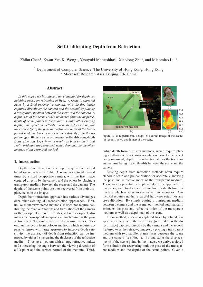
Figure 1. (a) Experimental setup; (b) a direct image of the scene;
(c) reconstructed depth map of the scene.
unlike depth from diffusion methods, which require plac-
ing a diffuser with a known orientation close to the object
being measured, depth from refraction allows the transpar-
ent medium being placed flexibly between the scene and the
camera.
Existing depth from refraction methods often require
elaborate setup and pre-calibration for accurately knowing
the pose and refractive index of the transparent medium.
These greatly prohibit the applicability of the approach. In
this paper, we introduce a novel method for depth from re-
fraction which is more usable in various scenarios. Our
method requires neither a careful hardware setup nor any
pre-calibration. By simply putting a transparent medium
between a camera and the scene, our method automatically
estimates the pose and refractive index of the transparent
medium as well as a depth map of the scene.
In our method, a scene is captured twice by a fixed per-
spective camera, with the first image (referred to as the di-
rect image) captured directly by the camera and the second
(referred to as the refracted image) by placing a transparent
medium with two parallel planar faces between the scene
and the camera (see Fig. 1). By analyzing the displace-
ments of the scene points in the images, we derive a closed
form solution for recovering both the pose of the transpar-
ent medium and the depths of the scene points. Given a
third image captured with the transparent medium placed in
a different pose, we further derive a closed form solution for
recovering also the refractive index of the medium. We call
our proposed method self-calibrating depth from refractionsince it directly exploits information obtained from the im-
ages of the scene to determine the necessary parameters for
estimating scene depth.
1.1. Related work
Depth acquisition has a long history in computer vision.
Based on the number of viewpoints required, existing meth-
ods can be broadly classified into multi-view and multi-
exposure approaches. Multi-view methods exploit stereo
information to recover the depth of a scene [13]. The loca-
tion of a 3D point can be estimated by finding and triangu-
lating correspondences across images.
Instead of moving the camera to change the viewpoints,
multi-exposure methods record the scene by changing the
imaging process. Depth from defocus methods obtain depth
by exploiting the fact that depth information is contained in
an image taken with a limited field of depth: objects at a
particular distance are focused in the image, while objects
at other distances are blurred by different degrees depend-
ing on their distances. Pentland estimated a depth map of
a scene by measuring the degree of defocus using one or
two images [12]. In [17], Subbarao and Gurumoorthy pro-
posed a simpler and more general method to recover depth
by measuring the degree of blur of an edge. Surya and Sub-
barao [18] used simple local operations on two images taken
by cameras with different aperture diameters for determin-
ing depth. Zhou et al. [20] pointed out that the accuracy of
depth is restricted by the use of a circular aperture. They
proposed a comprehensive framework to obtain an opti-
mized pair of apertures. All the aforementioned methods re-
quire large apertures to improve depth sensitivity. Recently,
Zhou et al. [19] proposed a depth from diffusion method.
Their method requires placing a diffuser with known orien-
tation near the scene. They showed that while depth from
diffusion is similar in principle to depth from defocus, it can
improve the accuracy of depth obtained with a small lens by
increasing the diffusion angle of a diffuser.
Our work is more closely related to [6, 9, 3, 4, 14, 15].
In [6], Lee and Kweon obtained the geometry of an ob-
ject using a transparent biprism. In [9] and [3], the au-
thors estimated the depth of a scene using a transparent pla-
nar plate with 2 opposite faces being parallel to the image
plane. In [4], Gao and Ahuja considered the case where the
faces of the transparent medium are not parallel to the im-
age plane, and images are captured by rotating the medium
about the principal axis of the camera. They estimated
the pose and the refractive index of the medium in an ex-
tra step using a calibration pattern. In [14, 15], Shimizu
and Okutomi proposed reflection stereo which records the
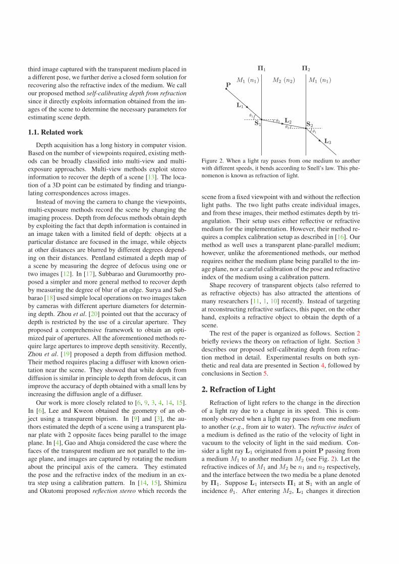
Figure 2. When a light ray passes from one medium to another
with different speeds, it bends according to Snell’s law. This phe-
nomenon is known as refraction of light.
scene from a fixed viewpoint with and without the reflection
light paths. The two light paths create individual images,
and from these images, their method estimates depth by tri-
angulation. Their setup uses either reflective or refractive
medium for the implementation. However, their method re-
quires a complex calibration setup as described in [16]. Our
method as well uses a transparent plane-parallel medium;
however, unlike the aforementioned methods, our method
requires neither the medium plane being parallel to the im-
age plane, nor a careful calibration of the pose and refractive
index of the medium using a calibration pattern.
Shape recovery of transparent objects (also referred to
as refractive objects) has also attracted the attentions of
many researchers [11, 1, 10] recently. Instead of targeting
at reconstructing refractive surfaces, this paper, on the other
hand, exploits a refractive object to obtain the depth of a
scene.
The rest of the paper is organized as follows. Section 2
briefly reviews the theory on refraction of light. Section 3
describes our proposed self-calibrating depth from refrac-
tion method in detail. Experimental results on both syn-
thetic and real data are presented in Section 4, followed by
conclusions in Section 5.
2. Refraction of LightRefraction of light refers to the change in the direction
of a light ray due to a change in its speed. This is com-
monly observed when a light ray passes from one medium
to another (e.g., from air to water). The refractive index of
a medium is defined as the ratio of the velocity of light in
vacuum to the velocity of light in the said medium. Con-
sider a light ray L1 originated from a point P passing from
a medium M1 to another medium M2 (see Fig. 2). Let the
refractive indices of M1 and M2 be n1 and n2 respectively,
and the interface between the two media be a plane denoted
by Π1. Suppose L1 intersects Π1 at S1 with an angle of
incidence θ1. After entering M2, L1 changes it direction
and results in a refracted ray L2 with an angle of refraction
θ2. By Snell’s law, the incident ray L1, the surface normal
at S1 and the refracted ray L2 are coplanar, and the angle of
incidence θ1 and the angle of refraction θ2 are related by
n1 sin θ1 = n2 sin θ2. (1)
After travelling for some distance in M2, L2 leaves M2 and
enters M1 again. Let the interface between M2 and M1 be
a plane denoted by Π2 which is parallel to Π1. Suppose
L2 intersects Π2 at S2 and after entering M1, it changes its
direction and results in a refracted ray L3. Since Π1 and
Π2 are parallel, it is easy to see that the angle of incidence
for L2 is θ2. It follows from Snell’s law that the angle of
refraction for L3 is θ1, and L1, L2, L3 and the surface nor-
mals of Π1 and Π2 are coplanar, with L1 parallel to L3.
Hence, the refraction plane of P (formed by L1, L2 and
L3) is perpendicular to both Π1 and Π2.
It is worth noting that total internal reflection might hap-
pen when a light ray passes from a medium with a higher
refractive index to one with a lower refractive index. The
critical angle is defined as the angle of incidence that re-
sults in an angle of refraction being 90◦. When the angle
of incidence is greater than the critical angle, total internal
reflection occurs and the light ray does not cross the inter-
face between the two media but is reflected totally back in
the original medium.
3. Depth from Refraction
In this section, we will derive a closed form solution for
recovering the depth of a scene from the displacements of
scene points observed in two images due to refraction of
light. As mentioned in Section 1, a scene will be captured
twice by a fixed perspective camera, with the first image
(referred to as the direct image) captured directly by the
camera and the second (referred to as the refracted image)
by placing a transparent medium between the scene and the
camera. We assume the intrinsic parameters of the camera
are known, and the transparent medium consists of two par-
allel planar faces through which light rays originate from
scene points enter and leave the medium before reaching
the camera.
3.1. Medium Surface ‖ Image Plane
Consider a 3D point P being observed by a camera cen-
tered at O (see Fig. 3). Let the projection of P on the image
plane be a point I. Suppose now a transparent medium Mwith two parallel planar faces is placed between P and the
camera in such a way that the two parallel planar faces are
parallel to the image plane. Due to refraction of light, Pwill no longer project to I. Let I′ be the new image posi-
tion for the projection of P. By considering the orthogonal
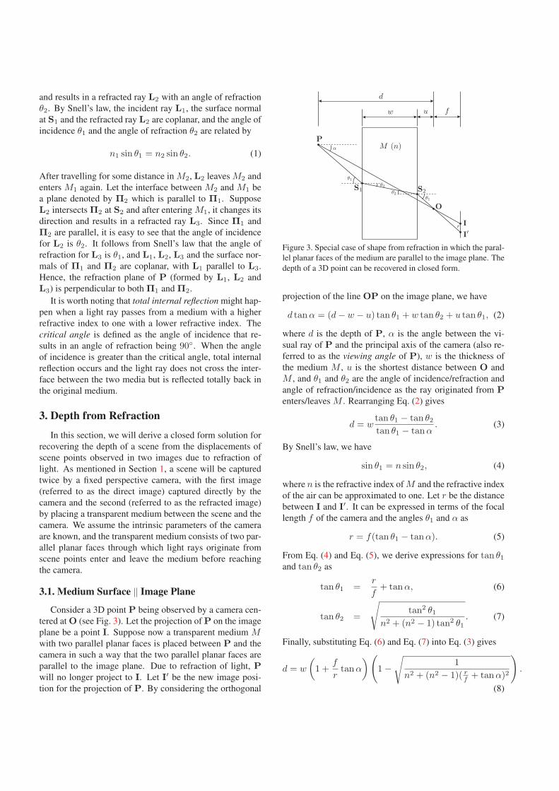
Figure 3. Special case of shape from refraction in which the paral-
lel planar faces of the medium are parallel to the image plane. The
depth of a 3D point can be recovered in closed form.
projection of the line OP on the image plane, we have
d tanα = (d − w − u) tan θ1 + w tan θ2 + u tan θ1, (2)
where d is the depth of P, α is the angle between the vi-
sual ray of P and the principal axis of the camera (also re-
ferred to as the viewing angle of P), w is the thickness of
the medium M , u is the shortest distance between O and
M , and θ1 and θ2 are the angle of incidence/refraction and
angle of refraction/incidence as the ray originated from Penters/leaves M . Rearranging Eq. (2) gives
d = wtan θ1 − tan θ2
tan θ1 − tanα. (3)
By Snell’s law, we have
sin θ1 = n sin θ2, (4)
where n is the refractive index of M and the refractive index
of the air can be approximated to one. Let r be the distance
between I and I′. It can be expressed in terms of the focal
length f of the camera and the angles θ1 and α as
r = f(tan θ1 − tanα). (5)
From Eq. (4) and Eq. (5), we derive expressions for tan θ1
and tan θ2 as
tan θ1 =r
f+ tanα, (6)
tan θ2 =
√tan2 θ1
n2 + (n2 − 1) tan2 θ1. (7)
Finally, substituting Eq. (6) and Eq. (7) into Eq. (3) gives
d = w
(1 +
f
rtanα
)(1 −
√1
n2 + (n2 − 1)( rf + tanα)2
).
(8)
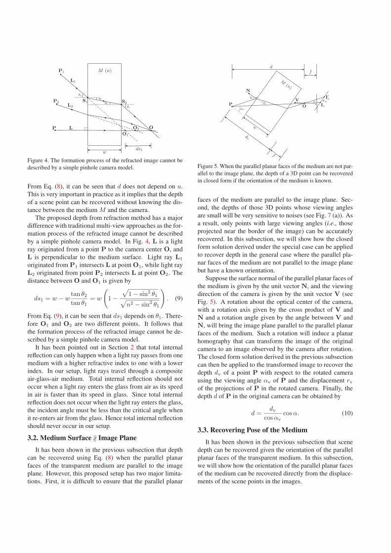
Figure 4. The formation process of the refracted image cannot be
described by a simple pinhole camera model.
From Eq. (8), it can be seen that d does not depend on u.
This is very important in practice as it implies that the depth
of a scene point can be recovered without knowing the dis-
tance between the medium M and the camera.
The proposed depth from refraction method has a major
difference with traditional multi-view approaches as the for-
mation process of the refracted image cannot be described
by a simple pinhole camera model. In Fig. 4, L is a light
ray originated from a point P to the camera center O, and
L is perpendicular to the medium surface. Light ray L1
originated from P1 intersects L at point O1, while light ray
L2 originated from point P2 intersects L at point O2. The
distance between O and O1 is given by
ds1 = w − wtan θ2
tan θ1= w
(1 −
√1 − sin2 θ1√n2 − sin2 θ1
). (9)
From Eq. (9), it can be seen that ds1 depends on θ1. There-
fore O1 and O2 are two different points. It follows that
the formation process of the refracted image cannot be de-
scribed by a simple pinhole camera model.
It has been pointed out in Section 2 that total internal
reflection can only happen when a light ray passes from one
medium with a higher refractive index to one with a lower
index. In our setup, light rays travel through a composite
air-glass-air medium. Total internal reflection should not
occur when a light ray enters the glass from air as its speed
in air is faster than its speed in glass. Since total internal
reflection does not occur when the light ray enters the glass,
the incident angle must be less than the critical angle when
it re-enters air from the glass. Hence total internal reflection
should never occur in our setup.
3.2. Medium Surface ∦ Image Plane
It has been shown in the previous subsection that depth
can be recovered using Eq. (8) when the parallel planar
faces of the transparent medium are parallel to the image
plane. However, this proposed setup has two major limita-
tions. First, it is difficult to ensure that the parallel planar
Figure 5. When the parallel planar faces of the medium are not par-
allel to the image plane, the depth of a 3D point can be recovered
in closed form if the orientation of the medium is known.
faces of the medium are parallel to the image plane. Sec-
ond, the depths of those 3D points whose viewing angles
are small will be very sensitive to noises (see Fig. 7 (a)). As
a result, only points with large viewing angles (i.e., those
projected near the border of the image) can be accurately
recovered. In this subsection, we will show how the closed
form solution derived under the special case can be applied
to recover depth in the general case where the parallel pla-
nar faces of the medium are not parallel to the image plane
but have a known orientation.
Suppose the surface normal of the parallel planar faces of
the medium is given by the unit vector N, and the viewing
direction of the camera is given by the unit vector V (see
Fig. 5). A rotation about the optical center of the camera,
with a rotation axis given by the cross product of V and
N and a rotation angle given by the angle between V and
N, will bring the image plane parallel to the parallel planar
faces of the medium. Such a rotation will induce a planar
homography that can transform the image of the original
camera to an image observed by the camera after rotation.
The closed form solution derived in the previous subsection
can then be applied to the transformed image to recover the
depth dv of a point P with respect to the rotated camera
using the viewing angle αv of P and the displacement rv
of the projections of P in the rotated camera. Finally, the
depth d of P in the original camera can be obtained by
d =dv
cos αvcos α. (10)
3.3. Recovering Pose of the Medium
It has been shown in the previous subsection that scene
depth can be recovered given the orientation of the parallel
planar faces of the transparent medium. In this subsection,
we will show how the orientation of the parallel planar faces
of the medium can be recovered directly from the displace-
ments of the scene points in the images.
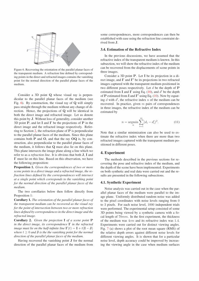
Figure 6. Recovering the orientation of the parallel planar faces of
the transparent medium. A refraction line defined by correspond-
ing points in the direct and refracted images contains the vanishing
point for the normal direction of the parallel planar faces of the
medium.
Consider a 3D point Q whose visual ray is perpen-
dicular to the parallel planar faces of the medium (see
Fig. 6). By construction, the visual ray of Q will simply
pass straight through the medium without any change of di-
rection. Hence, the projections of Q will be identical in
both the direct image and refracted image. Let us denote
this point by J. Without loss of generality, consider another
3D point P, and let I and I′ be the projections of P in the
direct image and the refracted image respectively. Refer-
ring to Section 2, the refraction plane of P is perpendicular
to the parallel planar faces of the medium. Since this plane
contains both P and O, and that the ray OQ is, by con-
struction, also perpendicular to the parallel planar faces of
the medium, it follows that Q must also lie on this plane.
This plane intersects the image plane along a line which we
refer to as a refraction line. It is obvious that both J, I and
I′ must lie on this line. Based on this observation, we have
the following proposition:
Proposition 1. Given the correspondences of two or morescene points in a direct image and a refracted image, the re-fraction lines defined by the correspondences will intersectat a single point which corresponds to the vanishing pointfor the normal direction of the parallel planar faces of themedium.
The two corollaries below then follow directly from
Proposition 1:
Corollary 1. The orientation of the parallel planar faces ofthe transparent medium can be recovered as the visual rayfor the point of intersection between two or more refractionlines defined by correspondences in the direct image and therefracted image.Corollary 2. Given the projection I of a scene point Pin the direct image, its correspondence I′ in the refractedimage must lie on the half-infinite line I′(t) = I + t(I − J)where t ≥ 0 and J is the the vanishing point for the normaldirection of the parallel planar faces of the medium.
Having recovered the vanishing point J for the normal
direction of the parallel planar faces of the medium from
some correspondences, more correspondences can then be
established with ease using the refraction line constraint de-
rived from J.
3.4. Estimation of the Refractive Index
In the previous discussions, we have assumed that the
refractive index of the transparent medium is known. In this
subsection, we will show the refractive index of the medium
can be recovered from the displacements of scene points in
three images.
Consider a 3D point P. Let I be its projection in a di-
rect image, and I′ and I′′ be its projections in two refracted
images captured with the transparent medium positioned in
two different poses respectively. Let d be the depth of Pestimated from I and I′ using Eq. (10), and d′ be the depth
of P estimated from I and I′′ using Eq. (10). Now by equat-
ing d with d′, the refractive index n of the medium can be
recovered. In practice, given m pairs of correspondences
in three images, the refractive index of the medium can be
estimated by
n = argminn
m∑i=1
(di − d′i)2. (11)
Note that a similar minimization can also be used to es-
timate the refractive index when there are more than two
refracted images captured with the transparent medium po-
sitioned in different poses.
4. ExperimentThe methods described in the previous sections for re-
covering the pose and refractive index of the medium, and
the depth of the scene have been implemented. Experiments
on both synthetic and real data were carried out and the re-
sults are presented in the following subsections.
4.1. Synthetic Experiment
Noise analysis was carried out in the case when the par-
allel planar faces of the medium were parallel to the im-
age plane. Uniformly distributed random noise was added
to the pixel coordinates with noise levels ranging from 0to 3 pixels. For each noise level, 1000 independent trials
were performed. The experimental setup consisted of some
3D points being viewed by a synthetic camera with a fo-
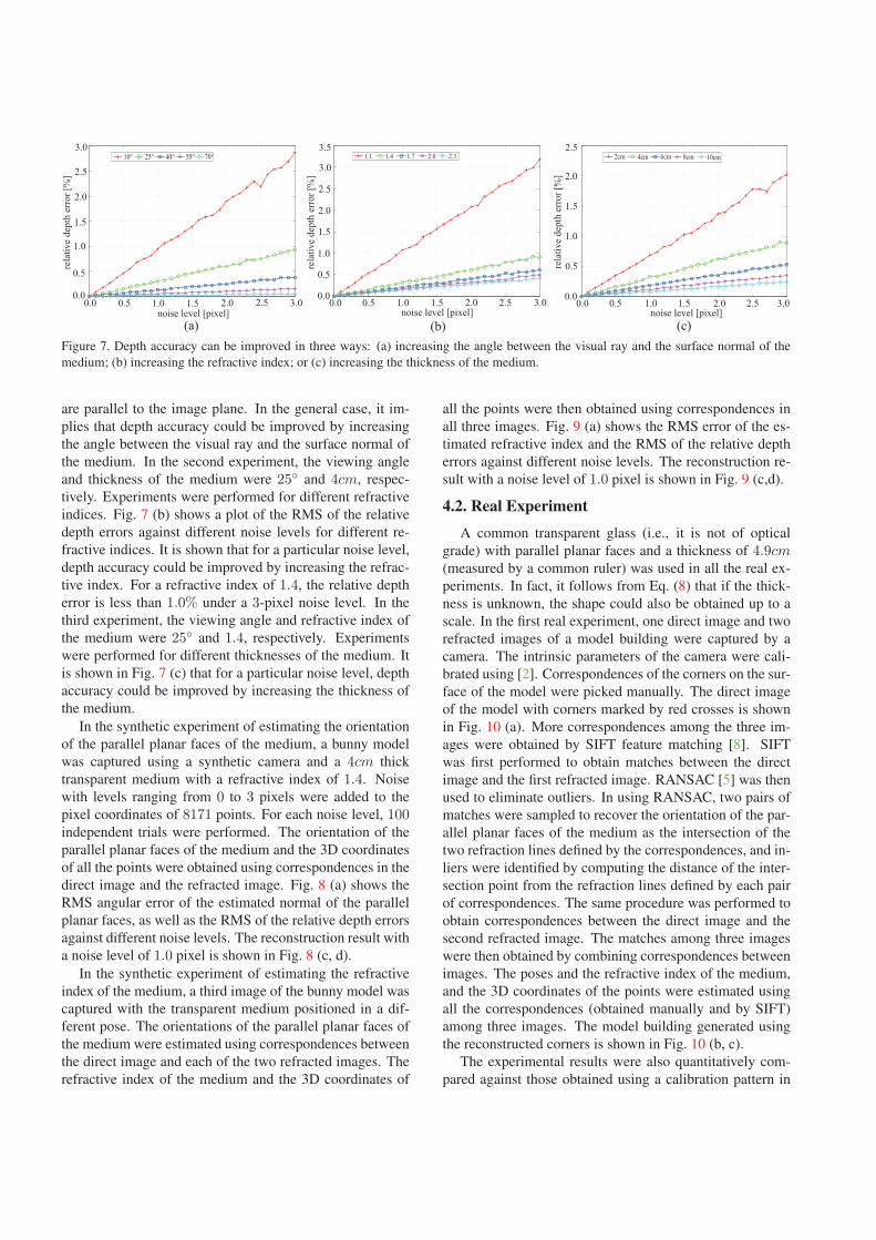
cal length of 70mm. In the first experiment, the thickness
of the medium was 4cm and its refractive index was 1.4.
Experiments were carried out for distinct viewing angles.
Fig. 7 (a) shows a plot of the root mean square (RMS) of
the relative depth errors against different noise levels for
different viewing angles. It is shown that for a particular
noise level, depth accuracy could be improved by increas-
ing the viewing angle in the case when medium surfaces
noise level [pixel]
0.00.0
0.5
1.0
1.5
2.0
2.5
3.0
rela
tive
dept
h er
ror [
%]
0.5 1.0 1.5 2.0 2.5 3.0
10° 25° 40° 55° 70°
0.0 0.5 1.0 1.5 2.0 2.5 3.00.0
0.5
1.0
1.5
2.0
2.5
3.0
3.5
noise level [pixel]re
lativ
e de
pth
erro
r [%
]
1.1 1.4 1.7 2.0 2.3
0.0 0.5 1.0 1.5 2.0 2.5 3.00.0
0.5
1.0
1.5
2.0
2.5
noise level [pixel]
rela
tive
dept
h er
ror [
%]
2cm 4cm 6cm 8cm 10cm
(a) (b) (c)Figure 7. Depth accuracy can be improved in three ways: (a) increasing the angle between the visual ray and the surface normal of the
medium; (b) increasing the refractive index; or (c) increasing the thickness of the medium.
are parallel to the image plane. In the general case, it im-
plies that depth accuracy could be improved by increasing
the angle between the visual ray and the surface normal of
the medium. In the second experiment, the viewing angle
and thickness of the medium were 25◦ and 4cm, respec-
tively. Experiments were performed for different refractive
indices. Fig. 7 (b) shows a plot of the RMS of the relative
depth errors against different noise levels for different re-
fractive indices. It is shown that for a particular noise level,
depth accuracy could be improved by increasing the refrac-
tive index. For a refractive index of 1.4, the relative depth
error is less than 1.0% under a 3-pixel noise level. In the
third experiment, the viewing angle and refractive index of
the medium were 25◦ and 1.4, respectively. Experiments
were performed for different thicknesses of the medium. It
is shown in Fig. 7 (c) that for a particular noise level, depth
accuracy could be improved by increasing the thickness of
the medium.
In the synthetic experiment of estimating the orientation
of the parallel planar faces of the medium, a bunny model
was captured using a synthetic camera and a 4cm thick
transparent medium with a refractive index of 1.4. Noise
with levels ranging from 0 to 3 pixels were added to the
pixel coordinates of 8171 points. For each noise level, 100independent trials were performed. The orientation of the
parallel planar faces of the medium and the 3D coordinates
of all the points were obtained using correspondences in the
direct image and the refracted image. Fig. 8 (a) shows the
RMS angular error of the estimated normal of the parallel
planar faces, as well as the RMS of the relative depth errors
against different noise levels. The reconstruction result with
a noise level of 1.0 pixel is shown in Fig. 8 (c, d).
In the synthetic experiment of estimating the refractive
index of the medium, a third image of the bunny model was
captured with the transparent medium positioned in a dif-
ferent pose. The orientations of the parallel planar faces of
the medium were estimated using correspondences between
the direct image and each of the two refracted images. The
refractive index of the medium and the 3D coordinates of
all the points were then obtained using correspondences in
all three images. Fig. 9 (a) shows the RMS error of the es-
timated refractive index and the RMS of the relative depth
errors against different noise levels. The reconstruction re-
sult with a noise level of 1.0 pixel is shown in Fig. 9 (c,d).
4.2. Real Experiment
A common transparent glass (i.e., it is not of optical
grade) with parallel planar faces and a thickness of 4.9cm(measured by a common ruler) was used in all the real ex-
periments. In fact, it follows from Eq. (8) that if the thick-
ness is unknown, the shape could also be obtained up to a
scale. In the first real experiment, one direct image and two
refracted images of a model building were captured by a
camera. The intrinsic parameters of the camera were cali-
brated using [2]. Correspondences of the corners on the sur-
face of the model were picked manually. The direct image
of the model with corners marked by red crosses is shown
in Fig. 10 (a). More correspondences among the three im-
ages were obtained by SIFT feature matching [8]. SIFT
was first performed to obtain matches between the direct
image and the first refracted image. RANSAC [5] was then
used to eliminate outliers. In using RANSAC, two pairs of
matches were sampled to recover the orientation of the par-
allel planar faces of the medium as the intersection of the
two refraction lines defined by the correspondences, and in-
liers were identified by computing the distance of the inter-
section point from the refraction lines defined by each pair
of correspondences. The same procedure was performed to
obtain correspondences between the direct image and the
second refracted image. The matches among three images
were then obtained by combining correspondences between
images. The poses and the refractive index of the medium,
and the 3D coordinates of the points were estimated using
all the correspondences (obtained manually and by SIFT)
among three images. The model building generated using
the reconstructed corners is shown in Fig. 10 (b, c).
The experimental results were also quantitatively com-
pared against those obtained using a calibration pattern in

(a) (d)(c)(b)0.0 0.5 1.0 1.5 2.0 2.5 3.0
0.0
0.2
0.4
0.6
0.8
1.0
1.2
1.4
rela
tive
dept
h er
ror [
%]
noise level [pixel]
angular errorrelative depth error
0.0
0.1
0.2
0.3
0.4
0.5
0.6
0.7
angu
lar e
rror
[deg
ree]
Figure 8. Reconstruction of the bunny using a direct image and a refracted image. (a) Estimation of the orientation of the parallel planar
faces of the medium and the depths of points on the surface of the bunny model; (b) the original bunny model; (c, d) two views of the
reconstructed bunny model.
relative depth errorerror of refractive index
rela
tive
dept
h er
ror [
%]
0
1
2
3
4
5
6
7
8
0.0 0.5 1.0 1.5 2.0 2.5 3.0noise level [pixel]
0.00
0.01
0.02
0.03
0.04
0.05
0.06
0.07
0.08
erro
r of r
efra
ctiv
e in
dex
(a) (b) (c) (d)Figure 9. Reconstruction of the bunny using a direct image and two refracted images captured with the transparent medium in two different
poses. (a) Estimation of the refractive index of the medium and the depth of points on the surface of the bunny model; (b) the original
bunny model; (c, d) two views of the reconstructed bunny model.
[3], which were treated as the ground truth. In the exper-
iment, depth of each corner in the pattern could be com-
puted by taking a direct image of the calibration pattern.
The ground truth of the first orientation of the medium and
the refractive index could then be estimated by using the
depths of the corners in the pattern. After calibration, the
model building was placed in the view of the camera with-
out moving the camera and medium. The angle between
the estimated normal of the medium and the ground truth
is 4.05◦. The ground truth refractive index is 1.438, and
the estimated index is 1.435. The reconstructed 3D points
were re-projected to the three images. The RMS of the re-
projection errors is 0.726 pixel.
In the second real experiment, one direct image and one
refracted image were used to obtain the depth map of the
scene. The orientation of the medium surface was esti-
mated from the correspondences in two images obtained
using SIFT. SIFT flow [7] was then used to obtain dense
correspondences across the two images. From the dense
correspondences, our method can recover a high-precision
result of a cat model, as shown in Fig. 11. Fig. 12 shows
the result of a more complicated scene recovered using the
same procedure. Note that the artifacts in both figures were
caused by the inaccuracy of correspondences obtained by
SIFT flow method.
(a) (b) (c)Figure 10. The reconstruction result of a model building. (a) A
direct image of the model with corners marked by red crosses;
(b,c) two views of the reconstructed model.
(a) (b) (c) (d)33.2[cm]
34.1
35.1
36.0
37.0
37.9
Figure 11. The reconstruction result of a model cat. (a) A direct
image; (b, c) two views of the reconstructed cat model; (d) depth
map of the model.

(a) (b)56.2
59.3
62.4
65.5
68.6
71.7
[cm]
(c) (d)Figure 12. The reconstruction result of a scene consisting of two
toy models. (a) A direct image; (b) depth map of the scene; (c, d)
two views of the reconstructed scene.
5. Conclusions
A self-calibrating depth from refraction method is intro-
duced in this paper. It is demonstrated that a transparent
medium with parallel planar faces can be used to recover
scene depth. Two images of a scene are captured by a cam-
era with and without placing a transparent medium between
the scene and the camera. Correspondences in images are
then used to obtain the orientation of the parallel planar
faces of the medium and the depths of scene points. It is
further pointed out that a third image with the medium po-
sitioned in another orientation could be used to estimate the
refractive index of the medium. Experiments on both syn-
thetic and real data show promising results. With the pro-
posed method, the pose and refractive index of the transpar-
ent medium, and depths of scene points can be estimated
simultaneously. Nevertheless, the proposed method suffers
from the same intrinsic limitation as other existing depth
from refraction methods: it corresponds to a small baseline
multi-view approach. Hence the proposed method could
only be used to recover depth for close scenes.
References[1] S. Agarwal, S. P. Mallick, D. Kriegman, and S. Belongie. On
refractive optical flow. In Proc. European Conf. on ComputerVision, pages 483–494, 2004. 2
[2] J.-Y. Bouguet. Camera calibration toolbox for matlab.
http://www.vision.caltech.edu/bouguetj/calib_doc/. 6
[3] C. Gao and N. Ahuja. Single camera stereo using planar
parallel plate. In Proc. Int. Conf. on Pattern Recognition,
volume 4, pages 108–111, 2004. 2, 7
[4] C. Gao and N. Ahuja. A refractive camera for acquiring
stereo and super-resolution images. In Proc. Conf. ComputerVision and Pattern Recognition, volume 2, pages 2316–2323,
2006. 2
[5] R. I. Hartley and A. Zisserman. Multiple View Geometryin Computer Vision. Cambridge University Press, second
edition, 2004. 6
[6] D. Lee and I. Kweon. A novel stereo camera system by a
biprism. IEEE Transactions on Robotics and Automation,
16:528–541, 2000. 2
[7] C. Liu, J. Yuen, and A. Torralba. Sift flow: Dense corre-
spondence across scenes and its applications. IEEE Trans.on Pattern Analysis and Machine Intelligence, 2010. 7
[8] D. Lowe. Object recognition from local scale-invariant fea-
tures. In Proc. Int. Conf. on Computer Vision, volume 2,
pages 1150–1157, 1999. 6
[9] H.-G. Maas. New developments in multimedia photogram-
metry. Optical 3-D Measurement Techniques III, 1995. 2
[10] N. Morris and K. Kutulakos. Dynamic refraction stereo. In
Proc. Int. Conf. on Computer Vision, volume 2, pages 1573–
1580, 2005. 2
[11] H. Murase. Surface shape reconstruction of a nonrigid trans-
port object using refraction and motion. IEEE Trans. onPattern Analysis and Machine Intelligence, 14:1045–1052,
1992. 2
[12] A. P. Pentland. A new sense for depth of field. IEEE Trans.on Pattern Analysis and Machine Intelligence, 9:523–531,
1987. 2
[13] S. M. Seitz, B. Curless, J. Diebel, D. Scharstein, and
R. Szeliski. A comparison and evaluation of multi-view
stereo reconstruction algorithms. In Proc. Conf. ComputerVision and Pattern Recognition, volume 1, pages 519–528,
2006. 2
[14] M. Shimizu and M. Okutomi. Reflection stereo - novel
monocular stereo using a transparent plate. In Proc. onCanadian Conference on Computer and Robot Vision, pages
CD–ROM, 2006. 2
[15] M. Shimizu and M. Okutomi. Monocular range estimation
through a double-sided half-mirror plate. In Proc. on Cana-dian Conference on Computer and Robot Vision, pages 347–
354, 2007. 2
[16] M. Shimizu and M. Okutomi. Calibration and rectification
for reflection stereo. In Proc. Conf. Computer Vision andPattern Recognition, pages 1–8, 2008. 2
[17] M. Subbarao and N. Gurumoorthy. Depth recovery from
blurred edges. In Proc. Conf. Computer Vision and PatternRecognition, pages 498–503, 1988. 2
[18] G. Surya and M. Subbarao. Depth from defocus by chang-
ing camera aperture: a spatial domain approach. In Proc.Conf. Computer Vision and Pattern Recognition, pages 61–
67, 1993. 2
[19] C. Zhou, O. Cossairt, and S. Nayar. Depth from diffusion. In
Proc. Conf. Computer Vision and Pattern Recognition, 2010.
2
[20] C. Zhou, S. Lin, and S. Nayar. Coded aperture pairs for depth
from defocus. In Proc. Int. Conf. on Computer Vision, pages
325–332, 2009. 2