self-degradable slag/class f fly ash-blend cements self-degradable slag/class f fly ash-blend...
TRANSCRIPT

BNL-94911-2011-IR
Self-degradable Slag/Class F Fly Ash-Blend Cements
Toshifumi Sugama, John Warren, and Thomas Butcher, Brookhaven National Laboratory;
Lance Brothers, Halliburton; Daniel Bour, AltaRock Energy, Inc.
March 2011
Sustainable Energy Technologies Department
Brookhaven National Laboratory
U.S. Department of Energy [DOE Office of Energy Efficiency and Renewable Energy],
[DOE Office of Geothermal Technologies] Notice: This manuscript has been authored by employees of Brookhaven Science Associates, LLC under Contract No. DE-AC02-98CH10886 with the U.S. Department of Energy. The publisher by accepting the manuscript for publication acknowledges that the United States Government retains a non-exclusive, paid-up, irrevocable, world-wide license to publish or reproduce the published form of this manuscript, or allow others to do so, for United States Government purposes.

DISCLAIMER
This report was prepared as an account of work sponsored by an agency of the United States Government. Neither the United States Government nor any agency thereof, nor any of their employees, nor any of their contractors, subcontractors, or their employees, makes any warranty, express or implied, or assumes any legal liability or responsibility for the accuracy, completeness, or any third party’s use or the results of such use of any information, apparatus, product, or process disclosed, or represents that its use would not infringe privately owned rights. Reference herein to any specific commercial product, process, or service by trade name, trademark, manufacturer, or otherwise, does not necessarily constitute or imply its endorsement, recommendation, or favoring by the United States Government or any agency thereof or its contractors or subcontractors. The views and opinions of authors expressed herein do not necessarily state or reflect those of the United States Government or any agency thereof.
1
Self-degradable Slag/Class F Fly Ash-Blend Cements
Prepared for
The U.S. Department of Energy
Energy Efficiency and Renewable Energy Geothermal Technologies Program
1000 Independence Avenue SW Washington, D.C. 20585
Prepared by
Toshifumi Sugama, John Warren, and Thomas Butcher Sustainable Energy Technologies Department
Brookhaven National Laboratory Upton, NY 11973-5000
Lance Brothers
Halliburton 2600 S. 2nd Street P.O. Drawer 1431
Duncan, OK 73536-0442
Daniel Bour AltaRock Energy, Inc.
7900 E. Green Lake Drive N., Suite 202 Seattle, WA 98103-4818
March 2011
Notice: This manuscript has been authored by employee of Brookhaven Science Associates, LLC under Contract No. DE-AC02-98CH 10886 with the U.S. Department of Energy. The publisher by accepting the manuscript for publication acknowledges that the United States Government retains a non-exclusive, paid-up, irrevocable, world-wide license to publish or reproduce the published form of this manuscript, or allow others to do so, for the United States Government purposes.

2
Abstract
Self-degradable slag/Class F fly ash blend pozzolana cements were formulated, assuming
that they might serve well as alternative temporary fracture sealers in Enhanced
Geothermal System (EGS) wells operating at temperatures of ≥ 200°C. Two candidate
formulas were screened based upon material criteria including an initial setting time ≥ 60
min at 85°C, compressive strength ≥ 2000 psi for a 200°C autoclaved specimen, and the
extent of self-degradation of cement heated at ≥200°C for it was contacted with water.
The first screened dry mix formula consisted of 76.5 wt% slag-19.0 wt% Class F fly ash-
3.8 wt% sodium silicate as alkali activator, and 0.7 wt% carboxymethyl cellulose (CMC)
as the self-degradation promoting additive, and second formula comprised of 57.3 wt%
slag, 38.2 wt% Class F fly ash, 3.8 wt% sodium silicate, and 0.7 wt% CMC. After mixing
with water and autoclaving it at 200°C, the aluminum-substituted 1.1 nm tobermorite
crystal phase was identified as hydrothermal reaction product responsible for the
development of a compressive strength of 5983 psi. The 200°C-autoclaved cement made
with the latter formula had the combined phases of tobermorite as its major reaction
product and amorphous geopolymer as its minor one providing a compressive strength of
5271 psi. Sodium hydroxide derived from the hydrolysis of sodium silicate activator not
only initiated the pozzolanic reaction of slag and fly ash, but also played an important
role in generating in-situ exothermic heat that significantly contributed to promoting self-
degradation of cementitious sealers. The source of this exothermic heat was the
interactions between sodium hydroxide, and gaseous CO2 and CH3COOH by-products
generated from thermal decomposition of CMC at ≥200°C in an aqueous medium. Thus,
the magnitude of this self-degradation depended on the exothermic temperature evolved
in the sealer; a higher temperature led to a sever disintegration of sealer. The exothermic
temperature was controlled by the extent of thermal decomposition of CMC,
demonstrating that CMC decomposed at higher temperature emitted more gaseous
reactants. Hence, such large emission enhanced the evolution of in-situ exothermic heat.
In contrast, the excessive formation of geopolymer phase due to more incorporation of
Class F fly ash into this cementitious system affected its ability to self-degrade, reflecting
that there was no self-degradation. The geopolymer was formed by hydrothermal
reactions between sodium hydroxide from sodium silicate and mullite in Class F fly ash.

3
Thus, the major reason why geopolymer-based cementitiuos sealers did not degrade after
heated sealers came in contact with water was their lack of free sodium hydroxide.
Introduction
In our ongoing project aimed at developing temporary cementitious sealing materials for
enhanced geothermal system (EGS) wells, BNL succeeded in formulating the self-
degradable sealer made with five starting materials: Granulated blast-furnace slag; Class
C fly ash; sodium silicate as an alkali activator; sodium carboxymethyl cellulose (CMC)
as a self-degradation promoting additive, and water [1]. The formulated cementitious
sealer had the following properties before its self-degradation occurred; initial- and final-
setting times of ~120 and ~180 min at 85°C; 2187 psi compressive strength with a
porosity of 36.5 % after autoclaving at 200°C; and 1825 to 1375 psi compressive strength
with 51.2 to 55.0 % porosity after the autoclaved sealers were heated between 200°C and
300°C. In addition, the developed sealer was formulated without the use of any Ordinary
Portland Cement (OPC), which causes the emission of 0.873 metric ton of CO2 [2] and a
great deal of mercury [3], while manufacturing one ton of OPC, strongly suggesting that
our cementitious sealer eliminates this carbon footprints and alleviates the environmental
impact. Similarly, our usage of slag and fly ash resources has beneficial environmental
effects. According to U.S. Geological Survey, in 2000, U.S steel industries generated 8.9
million tons of slag as wastes and by-products [4], and in 2009, 5.7 million tons of fly ash
by-products were yielded from U.S. coal combustion power plants [5]. Of these amounts,
5.1 million tons slag and 2.2 million tons fly ash were recycled into industrial products.
Thus, this abundant resource of these by-products as the starting materials of this
cementitious sealer assures the local availability across the U.S.A.
The self-degradation of sealer occurred, when the autoclaved sealer heated at
temperatures of ≥ 200°C came in contact with water. We interpreted the mechanism of
this water-initiated self-degradation as resulting from the in-situ exothermic reactions
between the reactants yielded from the hydrolysis of sodium silicate activator and the
thermal degradation of the CMC. The magnitude of self-degradation depended on the
CMC content; its effective content in promising degradation was ≥ 0.7 %. However, for

4
Class G well cement, CMC did not offer as effective as that of our cementitius system; no
self-degradation was noted from CMC-containing Class G well cement.
In this progress period, our focus concentrated on formulating and characterizing CMC-
containing slag/Class F fly ash-based self-degradable cement as an alternative temporary
fracture sealer for fractures in EGS wells. Then, we compared the physicochemical
properties of our candidate sealers with those of existing slag/Class C fly ash-based
sealing system. The parameters considered were the initial-setting time at 85°C, the
compressive strength and porosity in the range of 200°C to 300°C, the crystalline and
amorphous phases responsible for strengthening the sealer, and the exothermic
temperature promoting self-degradation of heated sealer after it contacted with water.
Experimental Procedure
Two industrial by-products with pozzolanic properties, granulated blast-furnace slag
under trade name “New Cem,” and Class F fly ash, were used as the hydraulic pozzolana
cement. The slag was supplied from Lafarge North America, and fly ash was obtained
from Boral Material Technologies, Inc. Table 1 lists their chemical constitutions. A
sodium silicate granular powder under trade name “Metos Bead 2048,” supplied by The
PQ Corporation, was used as the alkali activator of these pozzolana cements; its chemical
composition was 50.5 mol. wt % Na2O and 46.6 mol. wt % SiO2. The formula of the dry
pozzolana cements employed in this test had slag/Class F fly ash ratios of 100/0, 80/20,
60/40, 40/60, and 20/80 by weight. Sodium silicate powder served as alkali activator, and
its 4 % by the total weight of pozzolana cement was added to prepare the dry mix
cementitious reactant. For comparison purpose, the commercial Class G well cement was
used as control.
Sodium carboxymethyl cellulose (CMC) was produced by etherification of cellulose from
renewable resources, like wood. CMC under the production name “Walocel CRT 30
PA,” supplied by Dow Chemical Corp., was used as the thermal degradable additive to
promote the disintegration of the slag/Class F fly ash-based sealers; it dissolves in water,
forming an anionic polymer. Our previous work on slag/Class C fly ash system

5
demonstrated that an effective amount of CMC in promising self degradation was ≥ 0.7
% by total weight of dry slag/Class C fly ash/sodium silicate activator mixture. Thus, we
again used its 0.7 % in the current experiment.
The alkali-activated slag/Class F fly ash (AASF) slurries with CMC were prepared by
adding an appropriate amount of water to the dry mix cementitius component, and then
left them in an atmospheric environment until the cement set. Afterward, the room
temperature-set AASF samples were exposed in an autoclave at 200°C for 5 hours; some
autoclaved samples then were heated for 24 hours in over at 200°, 250°, and 300°C. The
commercial Class G well cement without CMC also was exposed to the same conditions
as that of AASF samples.
Measurements
The initial- and final-setting times of CMC-containing AASF sealing slurries at 85°C
were determined in accordance with modified ASTM C 191-92. In it, a slurry-filled
conical mold was placed in screw-topped round glass jar to avoid any evaporation of
water from slurry during heating. The slurry was examined every 30 minutes to
determine its setting time. The porosity of autoclaved and heated CMC-containing AASF
was measured by helium pyconometry. The specimens with size, 35 mm diameter x 70
mm length were used for porosity and compressive strength testing. X-ray powder
diffraction (XRD) and Fourier transform infrared spectroscopy (FT-IR) were used to
identify the crystalline and amorphous hydrothermal reaction products of the autoclaved
samples. The high-resolution scanning electron microscopy (HR-SEM) was employed to
survey any alternations in the microstructure of sealers before and after its self-
degradation, and also to explore the morphologies of the crystalline and amorphous
hydrothermal reaction products formed in sealers. To identify these reaction products, we
used energy-dispersible x-ray (EDX) concomitant with HR-SEM.
With a Type K thermometer, in conjunction with temperature data logger, we monitored
the heat energy generated in a self-degrading process of the 200°-, 250°-, and 300°C-
heated AASF specimens after their contact with water.

6
Results and Discussion
Properties of Slag/Class F fly ash System
Our first experiment was directed towards gaining data on the setting time and
compressive strength of CMC-containing AASF samples made with slag (S)/Class F fly
ash (F) ratios of 100/0, 80/20, 60/40, 40/60, and 20/80. Table 2 shows the changes in
water content, expressed as the ratio of water (w) to dry cement (c), as a function of the
S/F ratio used in preparing the AASF slurries; it includes their initial- and final-setting
times at 85°C. The water content in these AASF systems was adjusted to attain a
consistency similar to that of Class G well cement slurries made with the w/c ratio of
0.39. As is evident, the w/c ratio decreased with the replacement of some portion of slag
by Class F fly ash. The 0.47 w/c ratio of slurry made with 100/0 S/F ratio (no Class F fly
ash) declined by 15% to 0.40 when more than 60 wt% of slag was replaced by Class F fly
ash. For commercial Class G well cement, no initial set was apparent after exposure for
60 min in an oven at 85°C, but extending the exposure time to 90 min resulted in its final
set, demonstrating that both its initial- and final-setting took place within 30 min. In
contrast, all AASFs had at least 30-min span between the initial and final settings. The
elapsed time for AASF’s initial setting depended directly on the S/F ratios; with 100/0
S/F ratio, it was ~ 30 minutes, corresponding to a 60 min shorter than that of the Class G
slurries. Replacing 20% of the slag with fly ash delayed this initial setting time to ~ 60
minutes. A further delay was observed in the slurries made with the incorporation of
more Class F fly ash into slag. For instant, those slurries with a 60/40 and 40/60 S/F ratio
had an initial setting time of ~ 150 minutes and > 210 minutes, respectively. Furthermore,
the span between the initial and final setting times was related to the initial setting time;
namely, the slurries with a slower initial setting had a longer time span. In fact, this span
of 100/0 ratio with a fast initial setting of ~ 30 minutes was only 30 minutes. Compared
with this, a longer span of ~60 and ~120 min was observed from the 80/20 and 60/40
ratios along with ~ 60 and ~ 150 min initial setting time, respectively. Thus, a
predominance of slag in the mix seemingly accelerated both the initial- and final- setting
of slurries.

7
Figure 1 compares the compressive strength of the specimens made with 100/0, 80/20,
60/40, 40/60, and 20/80 S/F ratios after exposure to four different thermal conditions, as
described in Experimental Procedure. For comparison, Class G well cement was tested
under the same conditions. As is seen, two major factors governed the changes in
compressive strength for AASF systems: One factor was the S/F ratio; the other was the
subsequent temperature of heat exposure of the autoclaved specimens. For all the
specimens, excepting the 20/80 ratio one, autoclaving them at 200°C was responsible for
developing a higher compressive strength, rather than that the temperature to which they
subsequently were exposed to heat. The compressive strength of all autoclaved
specimens, excepting 20/80 ratio, were more than three-fold greater than that of
autoclaved Class G well cement. As described in our previous report, CMC additive as a
self degradation promoter in the sealer did not decompose hydrothermally in the
autoclave, but it was decomposed during the exposure in an over at temperatures of
≥200°C. Its decomposition therein led to the emission of several different gaseous species
such as CO2, CO, CH4, and CH3COOH, which created a porous cementitious structure
encompassing copious cavities and pores. This emission process was a major reason why
the compressive strength of all the heated specimens was lower than that of autoclaved
ones. Upon autoclaving, the extent of strength’s development depended on the S/F ratios;
the specimens made with this higher ratio displayed greater strength than those with
lower S/F ratios. In fact, the specimens with the 100/0 ratio had the highest compressive
strength of 6691 psi, corresponding to improvement of ~11, ~21, ~28, and ~88 % over
those with a ratio of 80/20, 60/40, 40/60, and 20/80.
On heating of autoclaved specimens at temperatures from 200°C to 300°C, the
compressive strength for all specimens, except for 20/80 ratio and Class G well cement,
tended to decline with rising temperature. With a 100/0 ratio, the compressive strength of
200°C-autoclaved specimens fell ~28 % to 4789 psi, when they were heated at 200°C. A
further increasing temperature to 250°C caused its reduction of ~ 39 %, while a 3683 psi
compressive strength at 300°C corresponded to ~ 45% reduction from the original value
of the autoclaved specimen. A similar tendency to decrease the compressive strength with
increasing temperature was observed in the autoclaved 80/20, 60/40, and 40/60 ratio

8
specimens. In contrast, no significant changes in compressive strength were observed in
20/80 ratio and Class G well cement specimens. As described in our previous report [1],
the major thermal decomposition curve of CMC by Differential scanning calorimetry
(DSC) revealed the beginning of decomposition at 165°C, the endothermic
decomposition peak at 270°C, and its end at 295°C. Since the temperature at the
endothermic peak represented the highest rate of thermal decomposition, a rise in the
heating temperature from 200°C to 300°C enhanced the emission of gaseous species
generated by the thermal decomposition of CMC. In the other words, rising temperature
promoted the rate of CMC solid→ gas phase transformation, reflecting directly the
development of porous structure in sealer.
Nonetheless, the development of in-situ porous cementitious structure along with a
retrogressed compressive strength at heating temperatures ≥ 200°C was a very important
aspect in subserving the disintegration of sealers through the self-degradation pathway
described in the introduction section.
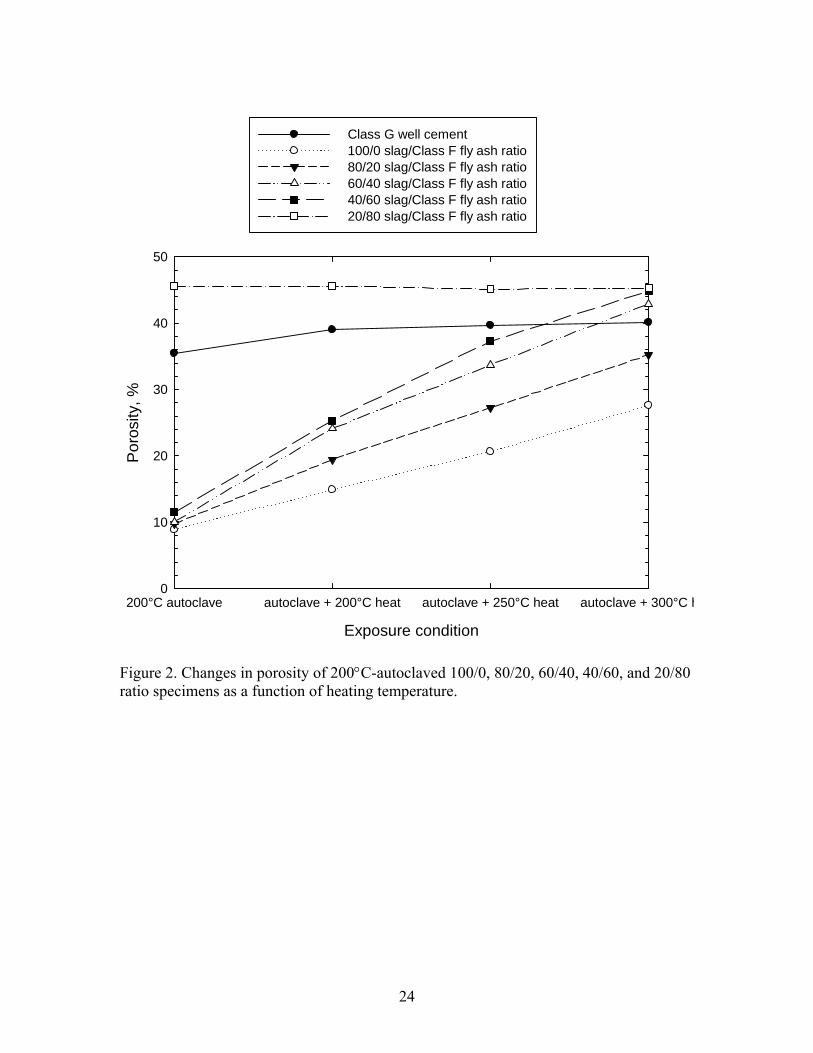
To verify this porosity-temperature relation, we determined the porosity of AASF and
Class G cement after exposing them to different heat temperatures (Figure 2). After
drying the autoclaved AASF specimens for 24 hours at 85°C, the porosity of the 100/0,
80/20, 60/40, and 40/60 ratios ranged from 8.9 to 11.5 %, while the 20/80 ratio had a
much higher porosity of 45.6 %. The autoclaved Class G cement had a porosity of 35.5
%. When these autoclaved specimens were heated in an oven at temperatures from
200°C to 300°C, the porosity of all AASF specimens, except for 20/80 ratio, markedly
increased with a rising heat temperature. Furthermore, the rate of increase in porosity was
associated with S/F ratio. With a 100/0 ratio, the porosity of the autoclaved specimens
rose 1.7-, 2.3-, and 3.1-fold to 14.9, 20.6, and 27.6%, respectively, at 200°, 250°, and
300°C. Compared with this, the specimens with a lower ratio of 40/60 resulted in the
incorporation of even more pores and voids into sealer, reflecting a 2.2-, 3.2-, and 3.9-
fold increase at 200°, 250°, and 300°C. As is evident, at 300°C, the efficiency of CMC in
creating a porous structure in the sealer was better than that at 200° and 250°C. In
addition, the sealers made with lower S/F ratios favorably incorporated more voids and

9
pores into their bodies, compared with those having a higher ratio. In contrast, neither the
Class G well cement nor specimens with a 20/80 ratio displayed any significant changes
in porosity as a function of temperature, suggesting that increased temperatures were not
as effective in incorporating additional pores and voids in them as in the other AASF
specimens.
Thus, the information described above clearly verified that exposure to higher
temperature assured a better performance of CMC in creating porous structure of sealers
than that to lower temperature.
XRD and FT-IR Analyses
To obtain information on what kind of hydrothermal reaction products contributed to the
development of strength in the AASF sealers, our attention now was paid to identifying
the crystalline and amorphous reaction products formed in the 200°C-autoclaved
specimens with various different S/F ratios.
Figure 3 depicts the XRD tracings, ranging from 5 to 51(2θ, degree), for autoclaved
AASF specimens, and also it includes “as-received” slag and Class F fly ash as the
starting materials. For slag, XRD pattern (a) revealed the typical amorphous feature of
CaO-Al2O3-MgO-SiO2 glass structure. The pattern (b) for Class F fly ash consisted of
three crystalline phases, quartz (SiO2), mullite (3Al2O3.2SiO2), and hamatite (Fe2O3). The
specimen made with 100/0 ratio (c) without Class F fly ash formed only single crystalline
phase associated with the calcium silicate hydrate (I) [CaO.SiO2.H2O, C-S-H (I)] as the
200°C hydrothermal-catalyzed pozzolanic reaction product, suggesting that the
hydrothermal reaction between slag and sodium silicate activator led to the formation of
C-S-H (I) phase responsible for strengthening 100/0 ratio specimen as illustrated below:
CaO.SiO2.H2OCaO-SiO2-Al2O3-MgO + z OH- + y (H2SiO4)2-
-(-Na2O.SiO2-)n-Hydrolysis
xNa+ + yH3SiO4- + zOH-
sodium silicate
slag C-S-H (I) phase
200°C-autoclave + n Al(OH)4
- +m Mg2+

10
In this reaction, the hydrolysis of sodium silicate activator in water generated two major
reactants, ionized monosilicic acid (H3SiO4-) and hydroxyl anion (OH-), and then these
ionic species reacted with slag to form C-S-H (I) phase. Replacing 20 % of the slag with
Class F fly ash, XRD pattern (d) with 80/20 ratio was characterized by forming the 1.1
nm tobermorite [Ca5(OH)2Si6O16.5H2O] phase, rather than C-S-H, while some non-
reacted Class F fly ashes remained in an autoclaved cementitious bodies. The similar
XRD pattern, except for the presence of more intensive d-spacing lines relative to the
remaining Class F fly ash, was observed from 60/40 ratio (e). Figure 4 shows the HR-
SEM images coupled to EDX-derived atomic compositions of both the Class F fly ash
remnant and tobermorite reaction products in the 60/40 ratio specimen. For the former,
the image revealed its typical micro-size spherical feature comprising three major
elements, oxygen, aluminum, and silicon, some of which were assignable to mullite and
quartz. The well-formed tobermorite was identified by the interlocking conformation of
thin plate-like crystals. EDX atomic composition of these crystal consisted of 19.2%
oxygen, 18.9 % aluminum, 29.0 % silicon, 31.6 % calcium, and 1.3 % iron. Among
those, three elements, oxygen, silicon, and calcium, belonged to the formation of
tobermorite. As well documented [6-8], aluminum element can be intercalated into the
structure of 1.1 nm tobermorite during hydrothermal curing condition around 180°C.
Thus, the presence of aluminum in this crystal demonstrated that this crystal formed
hydrothermally at 200°C was the aluminum-substituted 1.1 nm tobermorite,
Ca5AlSi5O16.5H2O. Thus, we believed that the aluminum liberated during interactions
between sodium silicate activator and Class F fly ash or slag/or both acted to form the
aluminum-substituted tobermorite crystal with a high molecular weight (MW) of 713.67,
compared to C-S-H (I) with a low MW of 134.14.
In contrast, a striking decay and disappearance of all tobermorite-related d-spacing lines
was observed from 40/60 S/F (f) and 20/80 S/F (g), while most of d-spacings in their
XRD patterns belonged to non-reacted Class F fly ash. Hence, it is possible to rationalize
that the strength developed in specimens made with Class F fly ash-predominated
formulas perhaps reflected not only poorly formed tobermorite, but also a possible

11
contribution from an amorphous reaction product yielded by the hydrothermal
interactions between sodium silicate activator and Class F fly ash.
To identify this amorphous reaction product, we analyzed 40/60 and 20/80 ratio
specimens using FT-IR. The “as-received” Class F fly ash and sodium silicate activator
were used as references. All specimens were dried in an oven at 85°C for 24 hours before
analyzing them. Figure 5 illustrates the resulting FT-IR spectra, ranging from 1800 to 500
cm-1, of both the specimens and references. For the references, a typical spectrum (a) of
sodium silicate had the following absorption bands: According to literatures [9-12], at
1635 cm-1 due to adsorbed H2O; at 1452 and 711 cm-1 associated with CO32- in
carbonates, at 1029 cm-1 ascribed to the oxygen-bridging Si-O-Si asymmetric stretching,
at 970 cm-1 reflecting non oxygen-bridging Si-O- stretching in Na+ -O-Si- linkage, at 882
cm-1 assigned to the Si-OH bending, and at 592 cm-1 attributed to the O-Si-O bending.
The spectrum of Class F fly ash (b) revealed the presence of four major groups;
carbonate-related CO32- at 1419 and 693 cm-1, silica-associated Si-O in-plane vibration at
1085 cm-1, silicate-related Si-O-Si linkage at 1029 cm-1, and tetrahedral aluminum-related
Si-O-Al linkage at 795 cm-1. Compared with that of Class F fly ash, the 40/60 S/F ratio
specimen exhibited three distinctive features (c): First, it developed a strong band at 1452
cm-1 attributed to the carbonates; second, a shoulder band at 1029 cm-1 corresponding to
Si-O-Si linkage in silicate became a pronounced band; thirdly, a strong new band at 970
cm-1 due to the Na+ -O-Si- linkage was emerged. Most of sodium silicate activator as the
starting material had dissolved in the cementitious slurry; in fact, the sharp O-Si-O band
at 592 cm-1 representing sodium silicate, did not see in this spectrum. As a result,
seemingly, the amorphous reaction product is likely to be the polymeric zeolite in terms
of geopolymer. As described in our previous paper [13], the geopolymer was assembled
through the three step-reaction pathways, alkali dissociation → interaction → self-
polycondensation (Figure 6). The first step of this pathway was the dissociation of mullite
in the Class F fly ash in the alkali medium derived from the hydrolysis of sodium silicate
activator, yielding two ionic reactants, Al(OH)4- and H3SiO4
-. The second step was the
interactions between these two anionic reactants and Na cation as a counter ion from
sodium silicate to form pre-geopolymer, and then the final step in assembling the

12
geopolymer was the self-polycondensation reactions between pre-geopolymers. Thus, the
amorphous geopolymer was responsible for the development of the compressive strength
of the 40/60 ratio specimen.
To visualize the morphology of amorphous geopolymer as cementitious binder, we
explored the fracture surface of autoclaved 40/60 ratio specimen using HR-SEM coupled
with EDX (Figure 7). The HR-SEM image revealed the cluster of fine fibrous-like
reaction products growing on the surfaces of Class F fly ash spheres, wherein, the
cohesively agglomerated masses of these cluster acted as cementitious structure. The
EDX atomic composition of this reaction product distinguished four major elements,
oxygen, sodium, aluminum, and silicon, attributed to geopolymer, along with three minor
elements, potassium, calcium, and iron. The geopolymer reaction products formed on the
surfaces of fly ash spheres, accounting for the interaction between sodium silicate and fly
ash. The image also revealed that this agglomerated microstructure contained numerous
voids, denoting that the geopolymer-based cementitious structure was poorly formed in
the 40/60 ratio specimen; and the incorporation of additional sodium silicate was needed
to create a well-formed geopolymer and to densify the geopolymer’s structure. Overall,
the phase composition assembled in the 40/60 ratio specimen was comprised of
amorphous geopolymer as the major reaction product and crystalline aluminum-
substituted 1.1 nm tobermorite as the minor one.
The XRD spectral feature of the 20/80 ratio (d) closely resembled to that of the 40/60
one, suggesting that the combination of geopolymer as the major phase and aluminum-
substituted 1.1 nm tobermorite as the minor one conferred the development of strength on
the 20/80 ratio specimen. Compared with the microstructure of the 40/60 ratio, the
microstructure of the 20/80 ratio was more porous, rich in voids. This was caused by two
undesirable factors: One factor was a very poor formation of geopolymer-based
cementitious structure including a copious number of pores; the other was related to a
large number of non-reacted Class F fly ash remnants. Although there was no presence of
FT-IR spectrum in any figures, the formation of geopolymer as the minor reaction
product was detected in the 60/40 ratio, but not in the 80/20 ratio.

13
Table 3 summarizes the compressive strength, porosity, and hydrothermal reaction
product for 100/0, 80/20, 60/40, 40/60, and 20/80 ratio specimens after autoclaving at
200°C. As is evident from table, the ranking of reaction products contributing to the
higher compressive strength and lower porosity was in the following order; crystalline C-
S-H (I) > crystalline aluminum-substituted 1.1 nm tobermorite > amorphous geopolymer.
Correspondingly, the poorly formed geopolymer-based cementitious structure in the
20/80 ratio had the highest porosity of 45.6 %, corresponding to the lowest compressive
strength. Additionally, the development of such porous structure was due not only to the
formation of void-rich geopolymer, but also reflected the presence of abundant non-
reacted Class F fly ash remnants.
Although the C-S-H (I)-associated 100/0 ratio specimen displayed outstanding
compressive strength and a denser structure, its one shortcoming was its rapid initial
setting of ~ 30 min at 85°C that failed to meet the criterion ≥ 60 min. Thus, no further test
was conducted for 100/0 ratio.
Self-degradation
Our focus next centered on visualizing the self-degradation of AASF sealers made with
80/20, 60/40, 40/60, and 20/80 S/F ratio. To do so, we adapted the same experimental
method as that of our previous work on the slag/Class C fly ash system. The detailed test
procedures were as follows; 1) the specimens were autoclaved at 200°C for 5 hours, and
then heated at 200°, 250°, and 300°C for 24 hours, 2) the specimens were cooled for 24
hours at room temperature, 3) thermocouple-embedded specimens were placed in a
vacuum chamber at -1000 kPa for 10 min to eliminate any air present in the specimens,
4) air-free voids in the vacuumed specimens were filled with water (water/specimens
volume ratio= 17/1), while determining the generation of in-situ exothermic heat by
temperature data logger, and 5) visual observation was made to evaluate the magnitude of
self-degradation.

14
Figure 8 plots the in-situ exothermic temperature generated in the vacuumed AASF
specimens as a function of elapsed time after they were impregnated with water. For
80/20 ratio, the resulting temperature-time relation cure showed that ~ 120 sec after
impregnating the specimen with water, its internal temperature rapidly rose from 16°C to
a peak of 40°C. The total elapse time from the onset to the maximum temperature was
only 238 sec. We observed the development of numerous cracks in the water-
impregnated specimens along with the increase in their exothermic temperature. Hence,
the penetration of water through the specimen led to the evolution of in-situ exothermic
heat promoting the self-degradation of the sealer. Although the similar feature of curve
was recorded in the 60/40 ratio specimen, its peak temperature was 9°C lower than that of
80/20 ratio, suggesting that more displacement of slag portion by Class F fly ash
engendered the reduction of in-situ exothermic heat evolved in the water-impregnated
specimen. We also observed that this 60/40 ratio specimen was degraded by water
penetration (Figure 9). Figure 10 compares the HR-SEM image of the fractured surfaces
for the 200°C-heated 60/40 ratio specimen before and after its self-degradation. Before a
self-degradation, the image showed a dense, relatively smooth surface texture as a typical
hard cementitious structure containing some non-reaction Class F fly ash spheres.
Compared with this, a dramatic alteration in microstructure was observed from the
fractured surface of self-degraded specimen. The image expressed that the ordinal
cementitious structure converted into a very rough, porous structure during a self-
degrading process, strongly demonstrating that the evaluation of in-situ exothermic heat
acted to promote an internal disintegration of the cementitious structure.
In contrast, there was no generation of the exothermic peak for 40/60 and 20/80 ratios.
Their curves revealed a slight increase in temperature after ~ 130 sec from the beginning
of water impregnation, but beyond this time, they leveled off. Furthermore, these
specimens did not show any signs of the self-degradation and - breakage, and nor were
visual cracks and fissures observed in the specimens.
Based upon out previous study [1], Figure 11 delineated the self-degradation mechanism
for alkali-activated cementitious material (AACM). In this mechanism, there were two

15
important factors: One factor was the presence of free sodium hydroxide as reactant
derived from the hydrolysis of sodium silicate activator in the AACM slurries; the other
was related to the formation of ionic carbonic acid from wet carbonation of CO2 emitted
from thermal degradation of CMC. The sodium hydroxide directly reacted with ionic
carbonic acid to form sodium bicarbonate. Then, the chemical affinity of sodium
bicarbonate with CH3COOH from the decomposed CMC led to the evolution of CO2 as
reaction product. In-situ exothermic energy was generated throughout this process,
including dissolution, interactions, and evolution. Nevertheless, we considered that this
in-situ CO2 gas evolution and sodium acetate as exothermic reaction product led to
volume expansion of AACM, thereby resulting in the breakage and disintegration of
AACM.
As is evident from this mechanism, the sodium hydroxide hydrolysate played a pivotal
role in promoting the self-degradation of sealers. In the 40/60 and 20/80 ratio specimens
comprising of geopolymer as the major reaction product, the amount of free sodium
hydroxide dissociated in the water-impregnated specimens may be very little, if any,
because the polymeric network structure of geopolymer was constituted of sodium
aluminum silicate compounds. Thus, it is reasonable to assume that the intercalation of
sodium in its polymeric networks impaired the production of sodium hydroxide, thereby
declining the evolution of in-situ exothermic heat promoting the self-degradation.
Correspondingly, the 20/80 ratio attributing to more consumption of sodium hydroxide to
form geopolymer had the lowest heat evolution. The lack of free sodium hydroxide was
the major reason why these geopolymer-based 40/60 and 20/80 ratio specimens remained
intact in terms of non-self degradation. Thus, although the geopolymer-based sealers had
a porous structure, its structure did not help in promoting the sealer’s self-degradation. As
a result, the magnitude of self-degradation was directed toward the exothermic
temperature generated in the water-impregnated sealers; a higher exothermic temperature
conferred adequate breakages on the sealer.
Returning to the self-degradation mechanism, the other important factor governing the
self-degradation was the amount of CO2 and CH3COOH as the gaseous by-products

16
emitted by the thermal decomposition of CMC. A large volume of these emitted by-
products in an aqueous medium would generate more exothermic heat by the interactions
between the carbonate or sodium hydroxide and CH3COOH. Thus, our focus next was
shifted to investigating the effectiveness of the thermal decomposition temperature of
CMC in rising this exothermic temperature. Figure 12 illustrates the exothermic
temperature-elapsed time relation for 80/20 ratio specimens after heating at 200°, 250°,
and 300°C. The data revealed the rise in peak exothermic temperature with an increasing
heat treatment temperature; in fact, the peak at 40°C evolved in the 200°C-heated
specimen shifted in a high temperature site to 42°C, when it was heated at 250°C. Further
shift to a higher temperature of 44°C was recorded from the 300°C-heated specimen. It
appeared from this result that the extent of exothermic heat evolution depended on the
thermal decomposition temperature of CMC. In the other words, the heat treatment at
300°C provided a better efficacy in enhancing the magnitude of self-degradation than that
at lower temperatures of 250° and 200°C.
With the 60/40 ratio, the exothermic temperature-elapsed time curve (Figure 13)
exhibited the similar trend to that of 80/20 ratio; the peak exothermic temperature
increased with an increasing heat treatment temperature. However, at 300°C, its highest
peak temperature of 41.5°C was 2.5°C lower than that of 80/20 ratio treated with the
same temperature, suggesting that the formation of some geopolymer in the 60/40 ratio
caused the reduction of exothermic heat evolution.
Conclusion
We evaluated in the laboratory a potential of alkali-activated slag/Class F (AASF)
cementitious system as an alternative self-degradable temporary sealing material. The
formulated AASF system included the five different slag/Class F fly ash (S/F) ratios,
100/0, 80/20, 60/40, 40/60, and 20/80. These formulas were modified with two additives:
One was sodium silicate as powdered alkali activator at 4 % of the total weight of dry
slag/Class F fly ash mixture; the other was sodium carboxymethyl cellulose (CMC)
powder as the self-degradation promoter at 0.7 % of the total weight of dry slag/Class F
fly ash/alkali activator blend. The three major material criteria for screening the candidate

17
temporary sealers were set: 1) An initial setting time of ≥ 60 min at 85°C, 2) compressive
strength ≥ 2000 psi after autoclaving at 200°C and heating at 200°, 250°, and 300°C, and
3) self-degrading capability when sealers hearted at ≥ 200°C came in contact with water.
The initial setting time at 85°C depended on the S/F ratios; a decrease in this ratio
extended setting time from ~ 30 min for 100/0 ratio to >210 min for 20/80 one. The phase
identification study for 200°C-autoclaved AASF specimens revealed that the crystalline
calcium silicate hydrate (I) [C-S-H (I)] as a hydrothermal reaction product was formed in
100/0 ratio specimen. Further, this reaction product contributed to the development of the
highest compressive strength of 6691 psi in this test series. No C-S-H (I) phase was
identified in any other S/F ratios. The aluminum-substituted 1.1 nm tobermorite phase
consisting of thin plate-like crystal was responsible for strengthening the specimens made
with 80/20 and 60/40 ratios, reflecting the compressive strength of 5983 psi to 5271 psi,
respectively. The latter ratio also encompassed a geopolymer phase as an amorphous
hydrothermal reaction product. Although 1.1 nm tobermorite was present as the minor
phase in the 40/60 and 20/80 ratios, amorphous geopolymer played the essential role in
developing their respective compressive strength of 4790 psi and 789 psi. However, the
geopolymer-based cementitious microstructure assembled in these ratio specimens was
porous, and hence undesirable. The incorporation of addition sodium silicate into these
ratios would be required to create a well-formed geopolymer and to densify its structure.
All autoclaved AASF specimens, except for 20/80 ratio, exhibited a decline in
compressive strength after heating ≥ 200°C; in fact, at 300°C, the strength of 100/0,
80/20, 60/40, and 40/60 ratios fell ~ 45, ~ 46, ~ 46, and ~ 57 %, compared with that of
autoclaved specimens. This decline in strength was correlated directory with an
increasing porosity in AASF bodies; at 300°C, the porosity of autoclaved 100/0, 80/20,
60/40, and 40/60 ratios, ranging from 8.9 % to 10.1 %, had increased, respectively, by
3.1-, 3.6-, 4.3-, and 3.9-fold. On heating at ≥200°C, the porous structure that developed in
the autoclaved specimens reflected the emission of CO2, CO, CH4, and CH3COOH as
gaseous by-products from the thermal decomposition of CMC. This emission was
enhanced with an increasing heat temperature, and accordingly, AASF specimens
exposed to higher temperatures had a more porous structure.
18
The 100/0 ratio failed to meet the criterion of initial setting time because it set quickly in
~ 30 min at 85°C. Thus, we did not explore its self-degradation. There were two factors
governing the magnitude of self-degradation of AASF sealers heated at ≥200°C, followed
by water impregnation: One factor was the hydrothermal reaction products responding to
the mechanical strength of sealers; the other was related to the thermal decomposition
temperature of CMC. In the first factor, aluminum-substituted 1.1 nm tobermorite phase
formed in the 80/20 and 60/40 ratio specimens allowed the sealer to disintegrate readily.
In contrast, the geopolymer phase formed in 40/60 and 20/80 ratio specimens prevented
the self-degradation of sealers, and they remained intact. Since the self-degradation of
sealer primary was due to the in-situ exothermic heat evolved by the interactions between
sodium hydroxide hydrolysate from sodium silicate, and CO2 and CH3COOH emitted by
thermal decomposition of CMC in an aqueous medium, it was very important for free
sodium hydroxide to be present in the sealer. However, the polymeric network structure
of geopolymer was assembled in the reactions between sodium hydroxide and mullite in
Class F fly ash. This was the major reason why the geopolymer-based sealer did not
disintegrate because the free sodium hydroxide had been consumed in assembling the
geopolymer structure.
Regarding the second factor, the increase in heat temperature generated more emission of
gaseous by-products from CMC, corresponding to an enhanced generation of in-situ
exothermic heat contributing to self-degradation. In fact, 300°C- and 250°C-heated 80/20
and 60/40 ratio sealers exhibited a higher exothermic temperature, compared with that of
200°C-heated same sealers. Based upon the visual observation, the sealers generating a
higher exothermic temperature underwent sever disintegration due to the development
and propagation of wide cracks and fissures. Therefore, we recommend the 80/20 and
60/40 ratio formulas as alternative self-degradable temporary sealers.
For comparison with the characterization of self-degradable slag/Class C fly ash systems
developed previously at BNL, Table 4 lists the properties of 20/80 slag/Class C fly ash
ratio-, and 80/20 and 60/40 slag/Class F fly ash ratio-based cementitious materials that

19
have high potential as temporary fracture sealers. These properties involved their initial
setting time at 85°C, compressive strength, porosity, phase composition as hydrothermal
reaction product, and the exothermic temperature evolved in 200°C- and 250°C- heated
sealers before and after autoclaving at 200°C. Nevertheless, we selected these three
formulas for a further R&D work on the development of the expansible temporary sealers
to improve their adherence to fractured inner-rock surfaces.
References
1. T. Sugama, T. Butcher, L. Brothers, and D. Bour “Self-degradable cementitious
sealing materials,” BNL-94308-2010-IR, October 2010.
2. S. Anand, P. Vrat, and R.P. Dahiya “Application of a system dynamics approach
for assessment and mitigation of CO2 emission from the cement industry,” J.
Environmental Management, 79 (2006) 383-398.
3. T. L. Mlakar, M. Horvat, T. Vuk, A. Stergarsek, J. Kotnik, J. Tratnik, and V.
Fajon “Mercury species, mass flows and processes in a cement plant,” Fuel, 89
(2010) 1936-1945.
4. R.S. Kalyoncu “Slag-iron and steel,” U.S. Geological Survey Minerals Yearbook,
2000. http://minerals.usgs.gov/minerals/pubs/commodity/iron_&_steel_slag/790400.pdf.
5. T.D. Kelly, D.E. Sullivan, and H. van Oss “Coal combustion products statistics,”
U.S. Geological Survey, Last modification: December 1, 2010.
http://minerals.usgs.gov/ds/2005/140/coalcombustionproducts.pdf.
6. L. Black, A. Stumm, K. Garbev, P. Stemmermann, K.R. Hallam, and G.C. Allen
“X-ray photoelectron spectroscopy of aluminum-substituted tobermorite,” Cem.
Concr. Res. 35 (2005) 51-55.
7. P. Faucon, J.C. Petit, T. Charpentier, J.F. Jacquinot, F. Adenot “Silicon
substitution for aluminum in calcium silicate hydrates,” J. Am. Ceram. Soc. 82
(1999) 1307-1321.
8. M. Mituda and H.F.W. Taylor “Influence of aluminum on the conversion of
calcium silicate hydrate gels into 1.1 nm tobermorite at 90° and 120°C,” Cem.
Concr. Res. 5 (1975) 203-210.

20
9. T. Uchino, T. Sakka, and M. Iwasaki “Interpretation of hydrated states of sodium
silicate glasses by infrared and raman analysis,” J. Am. Ceram. Soc. 74 (1991)
306-313.
10. B.N. Roy “Infrared spectroscopy of lead and alkaline-earth alumiosilicate
glasses,” J. Am. Ceram. Soc., 73 (1990) 846-855.
11. T. Uchino, T. Sakka, K. Hotta, and M. Iwasaki “Attenuated total reflectance
fourier-transform infrared spectra of a hydrated sodium silicate glass,” J. Am.
Ceram. Soc., 72 (1989) 2173-2175.
12. V.C. Farmer and J.D. Russell “The infra-red spectra of layer silicates,”
Spectrochim. Acta., 20 (1964) 1149-1173.
13. T. Sugama, T. Butcher, and L. Ecker “Experience with the development of
advanced materials for geothermal systems,” in Materials Challenges in
Alternative and Renewable Energy, [Ed.] G. Wicks, J. Simon, R. Zidan, E. Lara-
Curzio, T. Adams, J. Zayas, A. Karkamkar, R. Sindelar, and B. Garcia-Diaz, The
American Ceramic Society, Ceramic Transactions, 224 (2011) 389-401, A John
Wiley & Sons, Inc., Publication.

21
Table 1. Chemical composition of Ground Granulated Blastfurnace Slag and Class F fly
ash.
CaO,
wt% SiO2, wt%
Al2O3, wt%
MgO, wt%
Fe2O3, wt%
TiO2, wt%
Na2O, wt%
K2O, wt%
SO3, wt%
Loss in ignition for C, wt%
Slag 38.5 35.2 12.6 10.6 1.1 0.4 - - 0.1 1.5 Class F fly ash
0.47 39.3 38.6 1.4 12.9 - 1.5 1.9 1.2 2.7
Table 2. Water/cement ratio, and initial and final setting times at 85°C for slurries made with various slag/Class F fly ash ratio and Class G well cement. Water/cement, w/c
ratio Initial setting time at 85°C, min
Final setting time at 85°C, min
Class G well cement 0.39 ~90 ~90 100/0 slag/Class F 0.47 ~30 ~60 80/20 slag/Class F 0.45 ~60 ~120 60/40 slag/Class F 0.42 ~150 ~270 40/60 slag/Class F 0.40 >210 20/80 slag/Class F 0.40 >210 Table 3. Hydrothermal reaction products, compressive strength, and porosity for 200°C-autoclaved specimens made with 100/0, 80/20, 60/40, 40/60, and 20/80 slag/Class F fly ash ratios
Hydrothermal reaction product
Slag/Class F fly ash, ratio
Major phase Miner phase
Compressive strength, psi
Porosity, %
100/0 C-S-H (I) - 6691 8.9 80/20 tobermorite - 5983 9.7 60/40 tobermorite geopolymer 5271 10.1 40/60 geopolymer tobermorite 4790 11.5 20/80 geopolymer tobermorite 789 45.6

22
Table 4. Comparison of properties for representative self-degradable slag/Class C fly ash (S/C) and slag/Class F fly ash (S/F) sealing systems. Formula Initial
setting time at 85°C, min
Compressive strength, psi, after 200°C autoclave
Porosity, %, after 200°C autoclave
Phase composition after 200°C autoclave
Exothermic temperature for 200°C-heated sealers, °C
Exothermic temperature for 250°C-heated sealers, °C
20/80 S/C ratio
~ 60 2187 36.5 tobermorite, C-S-H (I)
41.5 Unknown
80/20 S/F ratio
~ 60 5983 9.7 tobermorite 40.0 42.7
60/40 S/F ratio
~ 150 5271 10.1 tobermorite, geopolymer
31.0 40.9

23
Exposure condition
200°C autoclave autoclave + 200°C heat autoclave + 250°C heat autoclave + 300°C h
Com
pres
sive
stre
ngth
, psi
0
1000
2000
3000
4000
5000
6000
7000
Class G well cement100/0 slag/Class F fly ash ratio80/20 slag/Class F fly ash ratio60/40 slag/Class F fly ash ratio40/60 slag/Class F fly ash ratio20/80 slag/Class F fly ash ratio
Figure 1. Compressive strength of the specimens made with 100/0, 80/20, 60/40, 40/60, and 20/80 ratios and Class G well cement after exposure in four different thermal environments.
24
Exposure condition
200°C autoclave autoclave + 200°C heat autoclave + 250°C heat autoclave + 300°C h
Por
osity
, %
0
10
20
30
40
50
Class G well cement100/0 slag/Class F fly ash ratio80/20 slag/Class F fly ash ratio60/40 slag/Class F fly ash ratio40/60 slag/Class F fly ash ratio20/80 slag/Class F fly ash ratio
Figure 2. Changes in porosity of 200°C-autoclaved 100/0, 80/20, 60/40, 40/60, and 20/80 ratio specimens as a function of heating temperature.

25
_ _ _ _ _
10 20 30 40 50
T : 1.1 nm Tobermorite
M : Mullite
: Quartz
: C-S-H
TH : Hamatite
M
HMM H
HT
T
H
H
H
T
T
TT
H
HH
TT T
T
T
T
H
TT
T
M HM
M H H
M
MM
(a)
(b)
(c)
(d)
(e)
(f)
(g)
2 Theta
Inte
nsity
(arb
. Uni
ts)
Figure 3. XRD patterns for slag (a), Class F fly ash (b), 200°C-autoclaved 100/0 (c), 80/20 (d), 60/40 (e), 40/60 (f), and 20/80 (g) slag/Class F fly ash ratio specimens.

26
Element
O Na Al Si K Ca Fe
Atom
ic c
ompo
sitio
n, %
0
10
20
30
40
50
60
Element
O Al Si Ca Fe
Atom
ic c
ompo
sitio
n, %
0
5
10
15
20
25
30
35
Figure 4. SEM images coupled with EDX atomic compositions for non-reacted Class F fly ash sphere (top) remained and aluminum-substituted 1.1 nm tobermorite crystal (bottom) formed in 200°C-autoclaved 60/40 slag/Class F fly ash ratio specimen.

27
_ _ _ _ _
8001700 1400 1100 500Wavenumber, cm-1
Tran
smitt
ance
(arb
. Uni
te)
1635
1029
1452
1419
1085
711
970
693
592
970
882
882
1452(a)
(b)
(c)
(d)
795
Figure 5. FT-IR spectra for “as-received” sodium silicate (a) and Class F fly ash (b), and 200°C-autoclaved 40/60 (c) and 20/80 (d) ratio specimens.

28
3Al2O3.2SiO2
OH OH
OH
Na+ -O-Al-O-Si-O-Al-OH
O-
OH OH
OH
Na+ -O-Al-O-Si-O-Al-OH
O-
OH
OH
OH
OH
Na+ -O-Al-O-Si-O-Al-OH + 3H2O
O-
OH
OH| | |
|
sodium silicate
Pre-geoplymer
mullite in fly ash
Step 1. Dissolution of aluminum silicate reactants in alkali medium
Step 2. Reaction between these dissociated ionic species
+ zOH-
-[NaO.SiO2-]n- + nH2O xNa+ + yH3SiO4- + zOH-
xAl(OH)4- + yH3SiO4
-
Na+ + H3SiO4- + 2Al(OH)4
-
Step 3. Self-polycondensation between pre-polymers
+
Geopolymer
| | |
|
| | |
|
+ nH2O
Figure 6. Formation of geopolymer assembled through three-step reaction pathways.

29
Element
O Na Al Si K Ca Fe
Atom
ic c
ompo
sitio
n, %
0
10
20
30
40
50
60
70
Figure 7. Microstructure and atomic composition of amorphous geopolymer formed in 200°C-autoclaved 40/60 slag/Class F fly ash ratio specimen.

30
Elapsed time, sec
0 100 200 300 400 500 600
Exot
herm
ic te
mpe
ratu
re, °
C
15
20
25
30
35
40
4580/20 slag/Class F fly ash ratio60/40 slag/Class F fly ash ratio40/60 slag/Class F fly ash ratio20/80 slag/Class F fly ash ratio
Figure 8. In-situ exothermic temperature vs. elapsed time for autoclaved 80/20, 60/40, 40/60, and 20/80 slag/Class F fly ash ratio specimens heated at 200°C after beginning impregnation with water.

31
Figure 9. Appearance of 200°C-heated 60/40 slag/Class F fly ash ratio specimens before (left) and after (right) water impregnation.

32
Figure 10. SEM images for fractured surfaces of 60/40 slag/Class F fly ash ratio specimens before (top) and after (bottom) self-degradation.

33
‐‐
‐
‐
‐
‐
‐‐
‐
Autoclaved Sealer
:CMC
: Free NaOH yielded by hydrolysis of sodium silicate
Heat
‐‐
‐‐
‐
‐
‐
‐‐
‐
‐
‐ ‐
‐‐‐
‐
CO2
CO
CH4
CH3COOH
‐
‐
Thermal decomposition of CMC
‐‐
‐
‐
‐
‐‐
‐
CO2
CO
CH4
CH3COOH
‐
‐Water penetration
+
H2O +
CO32‐ + 2H+
NaHCO3 + H2O
+
CH3COONa + H2O + CO2
Hydrolysis‐wet carbonation‐exothermic reaction
NaOHNaOH NaOH
Figure 11. Self-degradation scheme of heated CMC-containing sodium silicate-activated pozzolan cementitious materials after contact with water.

34
Elapsed time, sec
0 100 200 300 400 500 600
Exot
herm
ic te
mpe
ratu
re, °
C
15
20
25
30
35
40
45
50 After 200°C heatAfter 250°C heatAfter 300°C heat
Figure 12. Comparison of exothermic peak temperatures for 200°-, 250°-, and 300°C-heated 80/20 slag/Class F fly ash ratio specimens after water impregnation.

35
Elapsed time, sec
0 100 200 300 400 500 600
Exot
herm
ic te
mpe
ratu
re, °
C
15
20
25
30
35
40
45 After 200°C heatAfter 250°C heatAfter 300°C heat
Figure 13. Exothermic peak temperatures of 200°-, 250°-, and 300°C-heated 60/40 slag/Class F fly ash ratio specimens after water impregnation.