self inflating tires
TRANSCRIPT
i
SELF INFLATING TYRES
A seminar report submitted in partial fulfillment of the requirement for the degree
of
BACHELOR OF TECHNOLOGY
In
Mechanical Engineering
By
PAWAN TANDON
(Roll No. 1316440071)
Under the supervision of
Mr. Gaurav Kumar Upadhyay
Asst. Professor
Department of Mechanical Engineering
PRANVEER SINGH INSTITUTE OF TECHNOLOGY, KANPUR
March 2017
ii
CERTIFICATE
Certified that Mr. Pawan Tandon (Roll Number 1316440071) has carried out the seminar work
presented in this seminar entitled “Self-Inflating Tyres” from Pranveer Singh Institute of
Technology, Kanpur, affiliated by A.I.C.T.E and Uttar Pradesh Technical University,
Lucknow under my supervision. The seminar work embodies results of original work, and
studies are carried out by the student himself and the contents of the work do not form the basis
for the award of any other degree to the candidate or to anybody else from this or any other
University/Institution.
(Mr. Gaurav Kumar Upadhyay)
Assistant Professor
Department of Mechanical Engineering
Date: March 2017
P.S.I.T. Kanpur
iii
ABSTRACT
SELF INFLATING TYRES:-
Development in automobile engineering is the sign of rise in civilization. Along with
comfort and facilities it has revolutionized the living habits of the people to a great
extent. Large scale use of power window, steering system, anti-locking brakes, electronic
control of car, self-inflating tires etc., will not only reduce the operating cost but also add
standards in comfort. Self-inflating tires are one of them.
Tires are not carrying the weight of cars and trucks but it is the air inside the tires which
carries it. Run flat tires use a strong side wall material that supports the car even if there
is no air in one or more of the tires. This makes it possible to get where we are going
even if a tire is punctured and deflated. Run flat tires are constructed using alternating
layers of heat resistant cord and rubber and usually crescent –shaped wedges of weight-
supporting material, strengthening the sidewalls to prevent them from folding over when
there is no air pressure.
Self-inflating tires, on the other hand, are designed to constantly maintain tire pressure at
the proper level. Self-inflating systems are designed more for the slow leaks and for
optimizing performance and safety than for keeping a vehicle moving on a tire that will
no longer hold air. Self-inflating tires allow a vehicle to adjust to the current terrain for
ideal performance and safety in those conditions Currently, lots of consumer vehicles are
equipped with pressure-monitoring systems, but there's no way for the driver to do
anything about it without an external air source. There are lots of self-inflating-tire
systems on the market, but most of them are only available for commercial and military
application.
Self-inflating tires are those which are inflated to optimum desired pressure as and when
required. They allow a vehicle to adjust to the current terrain for ideal performance and
safety in those conditions. Most of the self-inflating systems are used for commercial and
military purpose.
iv
ACKNOWLEDGEMENT
I have a great pleasure in expressing my deep sense of gratitude indebtedness to my seminar
report mentor Mr. Gaurav Kumar Upadhyay (assistant professor), department of Mechanical
Engineering, PSIT, Kanpur, for his inspiring guidance, invaluable discussions for giving utmost
freedom and flexibility throughout progress of this seminar.
I have a gratification in expressing my sincere thanks to Mr. Nitin Srivastava, Head of
department of Mechanical Engineering, PSIT, Kanpur, for providing their necessary
departmental facilities during the course of the work.
Last but not the least, I am also thankful to all my faculty members, family, friends for providing
their valuable suggestions and guidance throughout the completion of seminar report.
.
DATE: March 2017 Pawan Tandon
ROLL NO: 1316440071

v
TABLE OF CONTENTS
Page no.
Abstract
List of tables 5
List of figures 6
Chapter1: - Introduction [7-14]
1.1 Tire Inflation Basic 7
1.2 Self-Inflating System 8
1.3 Central Tire Inflation System 9
1.4 Tire Maintenance System 12
1.5 Airgo System 13
Chapter2: -Literature survey and Scope of work [15-16]
2.1 Literature survey 15
2.2 Scope of work 15
Chapter3: - Working of SIT [17-18]
3.1 Peristaltic Pump 17
3.2 Working of SIT 17
3.3 Problems 18
3.4 How SIT Resolves the Problem? 18
Chapter4: -Conclusion 19
References 20
vi
LIST OF FIGURE
Description page no.
Fig. 1.1 Tires 7
Fig. 1.2 Central Tire Inflation System 10
Fig. 1.3 CTIS Arrangement 11
Fig. 1.4 Hummer Self Inflating Tires 12
Fig. 1.5 Air go System 14
vii
Chapter 1
Introduction
1.1 Tire Inflation Basic
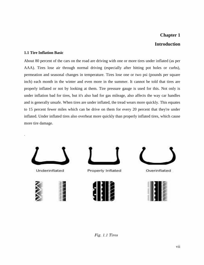
About 80 percent of the cars on the road are driving with one or more tires under inflated (as per
AAA). Tires lose air through normal driving (especially after hitting pot holes or curbs),
permeation and seasonal changes in temperature. Tires lose one or two psi (pounds per square
inch) each month in the winter and even more in the summer. It cannot be told that tires are
properly inflated or not by looking at them. Tire pressure gauge is used for this. Not only is
under inflation bad for tires, but it's also bad for gas mileage, also affects the way car handles
and is generally unsafe. When tires are under inflated, the tread wears more quickly. This equates
to 15 percent fewer miles which can be drive on them for every 20 percent that they're under
inflated. Under inflated tires also overheat more quickly than properly inflated tires, which cause
more tire damage.
.
Fig. 1.1 Tires
viii
As tires are flexible, they flatten at the bottom when they roll. This contact patch rebounds to its
original shape once it is no longer in contact with the ground. This rebound creates a wave of
motion along with some friction. When there is less air in the tire, that wave is larger and the
Friction created is greater -- and friction creates heat. If enough heat is generated, the rubber that
holds the tire's cords together begin to melt and the tire fails. Extra resistance of an under inflated
tire while rolling makes car’s engine to work harder. AAA statistics show that tires that are under
inflated by as little as 2 psi reduce fuel Efficiency by 10 percent.
1.2 Self-inflating systems
Tire-inflation systems have three general goals:
a) Detect when the air pressure in a particular tire has dropped - This means they have to
constantly (or intermittently) monitor the air pressure in each tire.
b) Notify the driver of the problem.
c) Inflate that tire back to the proper level - This means there has to be an air supply as well as
a check valve that opens only when needed.
1.2.1 Parts of any self-inflating system
While the available tire inflation systems vary in design, they share some common elements.
a) They all use some type of valve to isolate individual tires to prevent airflow from all tires
when one is being checked or inflated.
b) They have a method for sensing the tire pressures.
c) This is addressed in most cases with central sensors that relay information to an electronic
control unit and then to the driver.
d) They have an air source, which is usually an existing onboard source such as braking or
pneumatic systems. When using an existing system, however, they have to ensure that they
don't jeopardize its original function. For this reason, there are safety checks to ensure that
there is enough air pressure for the source's primary use before pulling air for tire inflation.
ix
e) There has to be a way to get the air from the air source to the tires, which is usually
through the axle. Systems either use a sealed-hub axle with a hose from the hub to the tire
valve or else they run tubes through the axle with the axle acting as a conduit.
f) There has to be a pressure relief vent to vent air from the tire without risking damage to the
hub or rear-axle seals.
1.3 Central tire inflation system (CTIS)
CTIS is provided to control the air pressure in each tire as a way to improve performance on
different surfaces. For example, lowering the air pressure in a tire creates a larger area of contact
between the tire and the ground and makes driving on softer ground much easier. It also does less
damage to the surface. This is important on work sites and in agricultural fields. By giving the
driver direct control over the air pressure in each tire, maneuverability is greatly improved.
Another function of the CTIS is to maintain pressure in the tires if there is a slow leak or
puncture. In this case, the system controls inflation automatically based on the selected pressure
the driver has set.
A wheel valve is located at each wheel end. For dual wheels, the valves are typically connected
only to the outer wheel so the pressure between the two tires can be balanced. Part of the wheel
valve's job is to isolate the tire from the system when it's not in use in order to let the pressure off
of the seal and extend its life. The wheel valve also enables on-demand inflation and deflation of
the tires.
An electronic control unit (ECU) mounted behind the passenger seat is the brain of the system.
It processes driver commands, monitors all signals throughout the system and tells the system to
check tire pressures every 10 minutes to make sure the selected pressure is being maintained.
The ECU sends commands to the pneumatic control unit, which directly controls the wheel
valves and air system. The pneumatic control unit also contains a sensor that transmits tire-
pressure readings to the ECU.
An operator control panel allows the driver to select tire-pressure modes to match current
conditions. This dash-mounted panel displays current tire pressures, selected modes and system
status. When the driver selects a tire- pressure setting, signals from the control panel travel to the
electronic control unit to the pneumatic control unit to the wheel valves. When vehicles are
moving faster (like on a highway), tire pressure should be higher to prevent tire damage.
x
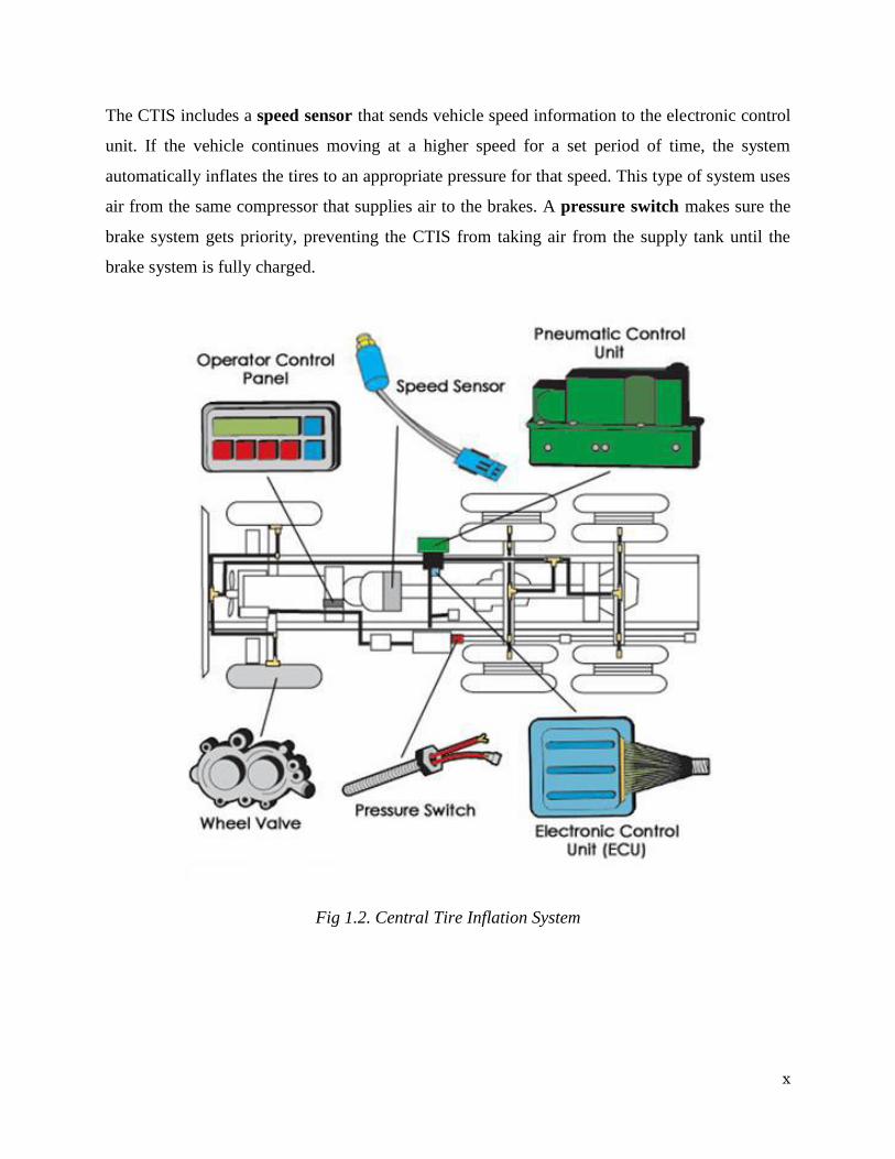
The CTIS includes a speed sensor that sends vehicle speed information to the electronic control
unit. If the vehicle continues moving at a higher speed for a set period of time, the system
automatically inflates the tires to an appropriate pressure for that speed. This type of system uses
air from the same compressor that supplies air to the brakes. A pressure switch makes sure the
brake system gets priority, preventing the CTIS from taking air from the supply tank until the
brake system is fully charged.
Fig 1.2. Central Tire Inflation System
xi
A CLOSER LOOK
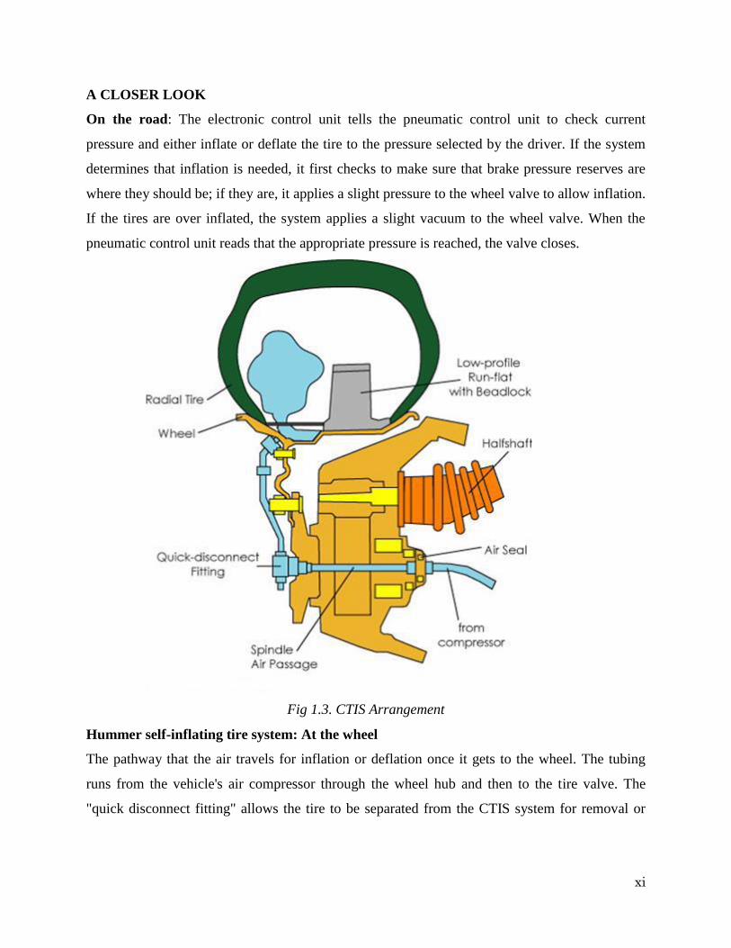
On the road: The electronic control unit tells the pneumatic control unit to check current
pressure and either inflate or deflate the tire to the pressure selected by the driver. If the system
determines that inflation is needed, it first checks to make sure that brake pressure reserves are
where they should be; if they are, it applies a slight pressure to the wheel valve to allow inflation.
If the tires are over inflated, the system applies a slight vacuum to the wheel valve. When the
pneumatic control unit reads that the appropriate pressure is reached, the valve closes.
Fig 1.3. CTIS Arrangement
Hummer self-inflating tire system: At the wheel
The pathway that the air travels for inflation or deflation once it gets to the wheel. The tubing
runs from the vehicle's air compressor through the wheel hub and then to the tire valve. The
"quick disconnect fitting" allows the tire to be separated from the CTIS system for removal or
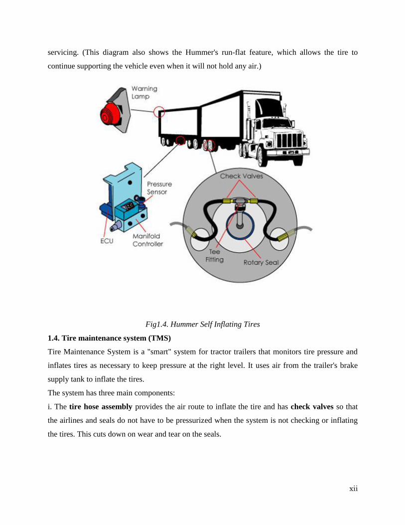
xii
servicing. (This diagram also shows the Hummer's run-flat feature, which allows the tire to
continue supporting the vehicle even when it will not hold any air.)
Fig1.4. Hummer Self Inflating Tires
1.4. Tire maintenance system (TMS)
Tire Maintenance System is a "smart" system for tractor trailers that monitors tire pressure and
inflates tires as necessary to keep pressure at the right level. It uses air from the trailer's brake
supply tank to inflate the tires.
The system has three main components:
i. The tire hose assembly provides the air route to inflate the tire and has check valves so that
the airlines and seals do not have to be pressurized when the system is not checking or inflating
the tires. This cuts down on wear and tear on the seals.

xiii
ii. The rotary joint is comprised of air and oil seals and bearings and connects the air hose from
the non-rotating axle to the rotating hubcap. Its air seals prevent leakage, and the oil seal
prevents contamination. The rotary hub also has a vent to release air pressure in the hubcap.
iii. The manifold houses the pressure protection valve, which makes sure the system doesn't pull
air if the brakes' air supply is below 80 psi. It also houses an inlet filter to keep the air clean, a
pressure sensor to measure tire pressures and solenoids that control airflow to the tires.
Like the CTIS, this system also has an electronic control unit that runs the entire system. It
performs checks to make sure the system is operational, notifies the driver via a warning light on
the trailer (visible through the rear-view mirror) if a tire’s pressure drops more than 10 percent
below its normal pressure and performs system diagnostics.
The system performs an initial pressure check and adds air to any tire that needs it. The check
valves in each tire hose ensure that the other tires don't lose pressure while one tire is being
inflated. After an initial pressure check, the system depressurizes to relieve pressure from the
seals. Every 10 minutes, the system pressurizes the lines and rechecks tire pressures.
The system measures tire pressure using a series of air pulses in the air lines. If the target
pressure in the line is not reached after a certain amount of time, the system begins inflating the
tire(s) until the correct pressure is reached.
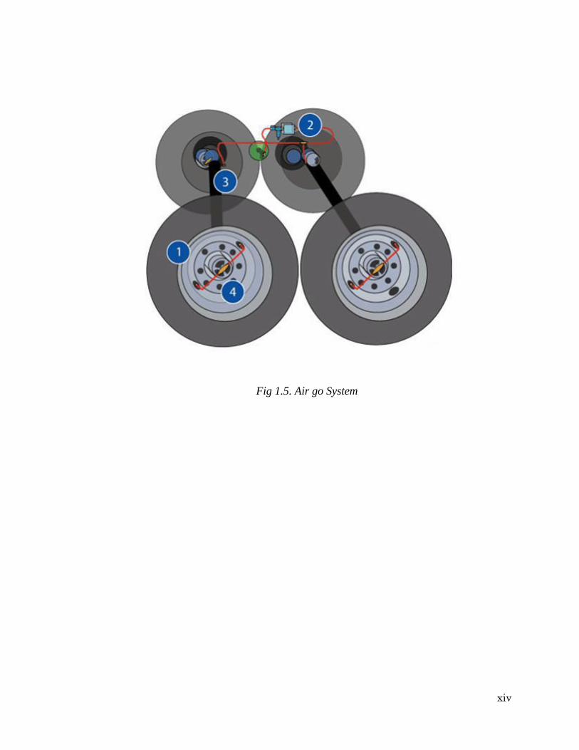
1.5. AIRGO system
The AIRGO system is a constant monitoring system that uses a series of check valves to detect a
loss in air pressure. Unlike some of the other systems, AIRGO doesn't use air from the vehicle's
braking system. When air seepage has occurred at any of various points in the system (1), the
system draws air (2) from the vehicle's pneumatic system (not shown) and sends it by way of
the vehicle's axles (3) through the axles themselves if they're pressurized or by way of tubing if
they're not -- through the hubcap assembly (4) and into the tire requiring inflation.
A warning light, located on the trailer but visible through the driver's rearview mirror,
illuminates when the system has inflated a tire.
Since this is a constant monitoring system, which puts a lot of wear and tear on the seals,
AIRGO uses carbon-graphite and case-hardened steel for its seals rather than rubber.
xiv
Fig 1.5. Air go System
xv
Chapter 2
Literature Survey & Scope of Work
2.1 Literature Survey
The aim of this study is to design and fabricate a system which works on automatic filling of air
into a tyre that is in running condition with a low cost device. It automatically checks the
pressure inside the tyre with the help of pressure gauge and ON the compressor which takes air
from atmosphere, compresses it and then delivers the compressed air to tyre and ensures that
tyres are always properly inflated to improve tyre life, human safety, reduction of gas mileage
and vehicle performance. As the wheel is in rotating condition while filling of air into it, rotary
joint is fixed between wheel spindle and wheel hub at each wheel so that there is no tangling of
hoses.
A system in which there is proper inflation in the tyre at all times which produce fuel savings of
1-4% and increase tyre life by up to 10%. A trial was done in this case paper involving two
cement tankers in NSW Australia operated over a period of 12 weeks in 2013. For first 6 weeks
central inflation system was turned ON in both tankers and for another 6 weeks central inflation
system was turned OFF in the both and graphs are prepared showing trucks with central inflated
system is good in conditions like average vehicle idle time, average vehicle time spent using
power take off, average vehicle GHG emissions, average vehicle fuel consumption across the
trial period.
2.2 Scope of work
There is a development of an active pressure-management system called TIPM (Tire Intelligent
Pressure Management), due to be available sometime. This system has a compressor that
automatically adjusts the pressure in each tire while the vehicle is in operation to compensate for
leaks and slow-leak punctures. The driver will be able to adjust the pressure depending on the
desired driving mode: comfort, sporty, all-terrain or over-obstacle. There are at least two other
systems in the early development stages that are oriented toward the consumer market -- the
Entire system and the Cycloid Air Pump system.
xvi
The Entire Self-inflating Tire system uses a valve that pulls in air from the atmosphere. It then
pumps the air into the under-inflated tire using a peristaltic-pump action. The goal is to
constantly maintain a specific pressure.
The Auto Pump tire-inflator system by Cycloid has a small, wheel-hub-mounted pump that is
powered by the turning of the wheels. When the system's monitor detects a dropin pressure of 2
to 3 psi, it pumps air into the under inflated tire. Auto Pump has a warning system that is
activated when there is a puncture.
The computer senses rotation using a rotation sensor on each wheel. If the computer were
programmed correctly and if there were a light on the dashboard, then the computer could detect
a flat tire. What the computer could do is look at different rotational speeds for one out of the
four wheels. A flat tire would spin faster than a properly inflated tire, so the computer would
look for one tire spinning faster than the other three, on average, over the course of a period of
time. Then it could warn the driver by activating the light on the dash.
1999 V1 installed in Daihatsu Charade.
xvii
CHAPTER-3
PARTS AND WORKING
3.1. Peristaltic Pump
Peristaltic Pump is used to pull atmospheric air and then pump it in to the under-inflated tire. It
has mainly three parts (A) Reservoir part (B) Peristaltic part and (C) Casing.
(A) Reservoir part: The reservoir part of SIT is used to store the inlet air drawn through the inlet
valve. The reservoir acts as a storehouse of the air drawn and supplies the necessary air during
any sudden drop in pressure of the tire. This reservoir thus helps in maintaining a constant
pressure of air.
(B) Peristaltic part: The peristaltic part is the thin tube, which is pressed by the roller or vane.
The reservoir part is followed by the peristaltic part. In this part there is single vane, which is
placed in place within the casing of the SIT.
(C) Casing: The casing is the outer part covering the peristaltic part of the SIT. The casing also
serves as the rim to hold the tire in place. Thus the casing serves two purposes in the tire. Rim
would create at cavity acting as the peristaltic pump. The casing has the property of withstanding
the pressure of the inside cavity and is able to keep the tire in place and thereby providing the
proper support to the tire.
3.2. Working of SIT:
The working of the Peristaltic system is explained in steps below.
1. The inlet valve situated before the reservoir part takes in atmospheric air.
2. The air taken in is stored in the reservoir part.
3. Air inside the reservoir part is taken inside the peristaltic part (thin tube) by the rotating rollers
connected to the rotor. The power for the rotation of the rotor is taken from the each revolution
of the tire.
xviii
4. The rollers compress the air inside the thin tube of the peristaltic part and the air pushed
through the outlet valve that is connected to the tube of the tire.
5. When the tire reaches its optimum pressure the inlet valve comes into act and prevents the
entry of atmospheric air into the reservoir part. Thus a constant pressure is maintained inside the
tire.
6. The following steps are repeated for every revolution of the tire.
3.3. Problem:
i. Under-inflated tires, which lose air due to normal driving or due to seasonal changes in
temperature loses one to two psi (pounds per square inch) each month causing tread wear.
ii. Under-inflated tires consumes more fuel and thus results in poor fuel economy.
iii. Under-inflated tires overheat more quickly causing more tire damage.
iv. Sometimes it may also lead to unstable driving and road accidents.
v. Under-inflated tire releases carbon dioxide in to the atmosphere, increases debris of destroyed
tire on road and thus are not environment friendly.
3.4. How SIT resolves the problem??
i. Self-inflated tires are filled with air at optimum desired level, almost every time, and thus
reducing the chances of tread wear.
ii. As the tires have sufficient air for smooth driving, engine works normally and do not require
to put extra effort and thus improving the fuel economy.
iii. Self-inflated tires do not overheat quickly and moves smoothly causing less tire damage.
iv. These tires help in proper driving and avoid road accidents.
v. Normally-inflated tire releases very less carbon dioxide to the atmosphere, less debris are
created and fewer scrap tires are generated and thus are environment friendly.

xix
Chapter 4
Conclusion
The Self-Inflating Tire System or Peristaltic Self-Inflating Tire System is able to continuously
inflate the tire at stable output pressure and eliminates the under-inflation faults.
The only limitation of the system is the user must be aware of the relationship between tire
pressure and road conditions.
The dynamically-self-inflating tire system would be capable of succeeding as a new product in
the automotive supplier industry. It specifically addresses the needs of the consumers by
maintaining appropriate tire pressure conditions for:
a) Reduced tire wear
b) Increased fuel economy
c) Increased overall vehicle safety because such a product does not currently exist for the
majority of passenger vehicles, the market conditions would be favorable for the introduction
of a self-inflating tire system. Through extensive engineering analysis, it has also been
determined that the self-inflating tire system would actually function as desired.
In particular, the product would be capable of:
i. Providing sufficient airflow to the tire with minimal leakage.
ii. Withstanding the static and dynamic loading exerted on the rotary joints Note that likewise,
this system would not produce any negative dynamic effects (such as CV joint failure due to
resonance) on surrounding systems. Most significantly, the self-inflating tire system would be a
successful product because of its economic benefits to investors. Specifically, the final product
would: Sell at about $450/unit, with total first year profit and sales of nearly $2.1 million and
58,000units, respectively. Experience 12% annual market growth each year for the first five
years of the product, bringing total sales up to 370,000 units • Break-even on the capital
investment in just under three years For further development of this product, we recommend
increasing the capability of the system by adding the following features. Pressure adjustment
based on increasing vehicle speed. Pressure adjustment based on increasing vehicle load.
Adaptability for recreational use (inflating rafts, sports balls, etc.) Implementation of interactive
display.
xx
2008
References: -
IJSRD - International Journal for Scientific Research & Development| Vol. 4, Issue 03,
2016 | ISSN (online): 2321-0613
United States Patent October 2001 US 6,305,245 B1
International Journal of Scientific and Research Publications Volume 6 Issue 3 March
2016 ISSN 2250-3153