semi-brittle deformation · name _____ geol 255 – structural geology lab #4 spring 2017 due...
TRANSCRIPT
Name __________________________________ Geol 255 – Structural Geology Lab #4 Spring 2017 Due Thursday, March 2
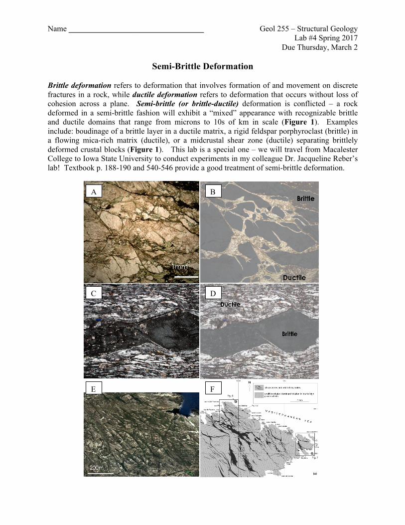
Semi-Brittle Deformation Brittle deformation refers to deformation that involves formation of and movement on discrete fractures in a rock, while ductile deformation refers to deformation that occurs without loss of cohesion across a plane. Semi-brittle (or brittle-ductile) deformation is conflicted – a rock deformed in a semi-brittle fashion will exhibit a “mixed” appearance with recognizable brittle and ductile domains that range from microns to 10s of km in scale (Figure 1). Examples include: boudinage of a brittle layer in a ductile matrix, a rigid feldspar porphyroclast (brittle) in a flowing mica-rich matrix (ductile), or a midcrustal shear zone (ductile) separating brittlely deformed crustal blocks (Figure 1). This lab is a special one – we will travel from Macalester College to Iowa State University to conduct experiments in my colleague Dr. Jacqueline Reber’s lab! Textbook p. 188-190 and 540-546 provide a good treatment of semi-brittle deformation.
A B
DC
E F
2
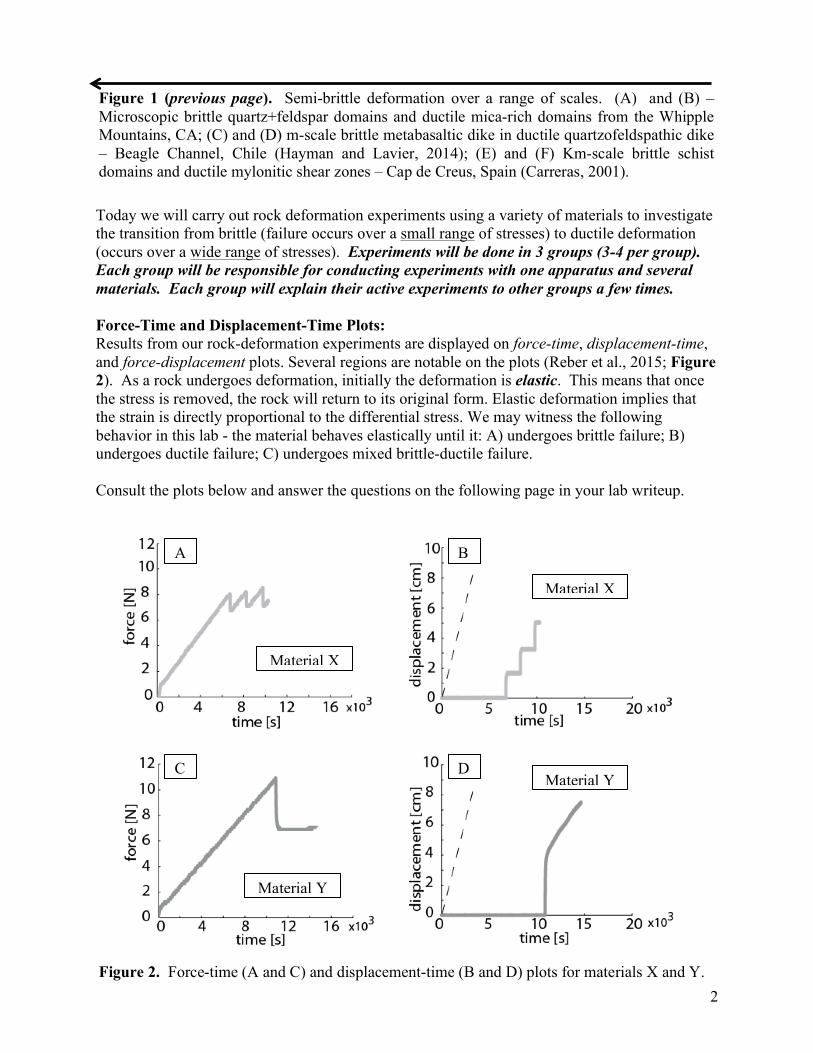
Today we will carry out rock deformation experiments using a variety of materials to investigate the transition from brittle (failure occurs over a small range of stresses) to ductile deformation (occurs over a wide range of stresses). Experiments will be done in 3 groups (3-4 per group). Each group will be responsible for conducting experiments with one apparatus and several materials. Each group will explain their active experiments to other groups a few times. Force-Time and Displacement-Time Plots: Results from our rock-deformation experiments are displayed on force-time, displacement-time, and force-displacement plots. Several regions are notable on the plots (Reber et al., 2015; Figure 2). As a rock undergoes deformation, initially the deformation is elastic. This means that once the stress is removed, the rock will return to its original form. Elastic deformation implies that the strain is directly proportional to the differential stress. We may witness the following behavior in this lab - the material behaves elastically until it: A) undergoes brittle failure; B) undergoes ductile failure; C) undergoes mixed brittle-ductile failure. Consult the plots below and answer the questions on the following page in your lab writeup.
Figure 1 (previous page). Semi-brittle deformation over a range of scales. (A) and (B) – Microscopic brittle quartz+feldspar domains and ductile mica-rich domains from the Whipple Mountains, CA; (C) and (D) m-scale brittle metabasaltic dike in ductile quartzofeldspathic dike – Beagle Channel, Chile (Hayman and Lavier, 2014); (E) and (F) Km-scale brittle schist domains and ductile mylonitic shear zones – Cap de Creus, Spain (Carreras, 2001).
A B
C D
Figure 2. Force-time (A and C) and displacement-time (B and D) plots for materials X and Y.
Material X
Material X
Material Y
Material Y
3
Light stretching questions: Plots A and B were made following deformation of material X; plots C and D show how a different material (material Y) responded to deformation.
A) How does elastic deformation appear on each plot? How about brittle slip? Ductile creep? B) Why does the force occasionally suddenly drop on plots A and C? What real-world
phenomenon do these drops represent? C) Compare materials X and Y. Which deforms more brittle-ly/ductile-ly? Why?
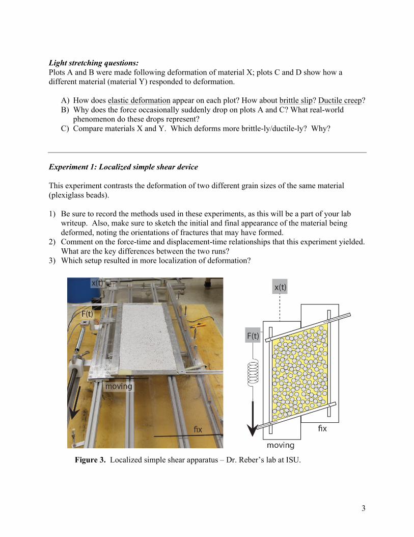
Experiment 1: Localized simple shear device This experiment contrasts the deformation of two different grain sizes of the same material (plexiglass beads). 1) Be sure to record the methods used in these experiments, as this will be a part of your lab
writeup. Also, make sure to sketch the initial and final appearance of the material being deformed, noting the orientations of fractures that may have formed.
2) Comment on the force-time and displacement-time relationships that this experiment yielded. What are the key differences between the two runs?
3) Which setup resulted in more localization of deformation?
Figure 3. Localized simple shear apparatus – Dr. Reber’s lab at ISU.
4
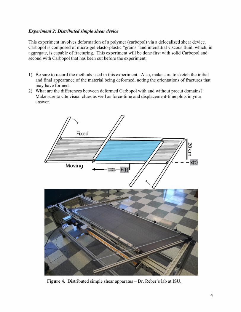
Experiment 2: Distributed simple shear device This experiment involves deformation of a polymer (carbopol) via a delocalized shear device. Carbopol is composed of micro-gel elasto-plastic “grains” and interstitial viscous fluid, which, in aggregate, is capable of fracturing. This experiment will be done first with solid Carbopol and second with Carbopol that has been cut before the experiment. 1) Be sure to record the methods used in this experiment. Also, make sure to sketch the initial
and final appearance of the material being deformed, noting the orientations of fractures that may have formed.
2) What are the differences between deformed Carbopol with and without precut domains? Make sure to cite visual clues as well as force-time and displacement-time plots in your answer.
Figure 4. Distributed simple shear apparatus – Dr. Reber’s lab at ISU.

5
Experiment 3: Pressure cell This experiment involves injection of pressurized air into gelatin, flour, and carbopol in a Hele-Shaw Cell. 1) Be sure to record the methods used in this experiment. Also, make sure to sketch the initial
and final appearance of the material being deformed, noting the orientations of fractures that may have formed.
2) What effect does air injection have on the three deformed materials? In your explanation, be sure to invoke your knowledge of Mohr diagrams and pore pressure.
3) What are the differences between the three deformed materials? In other words, how strongly does material rheology govern the fracture pattern? Make sure to cite visual clues as well as pressure-time plots in your answers.
Important Terminology: Yield point: The point where a rock can no longer return to its original shape. Brittle failure: Rock fractures and can no longer support the stress. Plastic deformation: Deformation of the rock that is permanent but before brittle failure. Strain hardening: The rock becomes resistive to strain requiring more stress for deformation. Strain softening: The rock becomes weaker requiring less stress for deformation.
Lab writeup: You’ve now deformed a variety of materials in a variety of ways, constructed plots, and interpreted the data. Like the lab, the writeup will be done as a group, but group members will be scrambled so there is at least one person who completed experiment 1, 2, and 3 in each group. Your lab deliverable will be a brief report, which should contain the following sections: 1) Abstract – a brief (200-300 words) synopsis of the project. Consult the “suggestions for preparing a good abstract” section of the class project writeup (on Moodle) for an idea of how to lay this out. 2) Introduction – briefly (a paragraph or so) identify the problems we’re addressing and how we’re addressing them. 3) Methods – discuss what we did (setting up and carrying through the experiment). The experiments we performed in this lab are designed to improve our understanding of natural deformation. With this in mind, list and discuss 2-3 limitations of the physical experiments we performed in this lab. 4) Results and discussion – Answer the “light stretching questions” and all questions associated with experiments 1, 2, and 3. Include before/after sketches and/or annotated photos of the experiments. Construct plots that will help you make your points clearly. Discuss your data and what you think it all means. Integrating what you’ve learned, think at a bigger scale – what do these experiments tell us about natural deformation processes? 5) Conclusions – a brief summary of what was done, how you did it, and what it all means!