semi-hermetic scroll refrigerant compressor - … tecnica/compresores/chyntec/chyntec ts… ·...
TRANSCRIPT
Semi-hermetic
Scroll Refrigerant Compressor
Technical Manual
ChynTec International Co., Ltd.
August, 2008

Contents
0. General Technical Information ……………………………… 2
1. Operating Principle of Scroll Compressor ……………………………… 3
2. Sectional View of Compressor ……………………………… 5
3. Compressor Nomenclature & Illustration ……………………………… 6
4. Operating Envelopes and Limitations ……………………………… 7
5. Mechanical Specifications ……………………………… 9
6. Dimensions of Compressors ……………………………… 16
7. Electrical Design ……………………………… 20
8. System Design & Application Advice ……………………………… 24
9. Optional Accessories ……………………………… 28
10. Maintenance ……………………………… 30
11. Dimensions of Intake and Outlet Flange ……………………………… 31 ISO9001:2000
Note: This manual is for technical reference only. ChynTec International reserves the right to revise the details shown herein without notification in advance.
1

2
General Technical Information:
1. Deliberately discharge of environmentally harmful refrigerants shall be avoided. 2. When selecting a refrigerant, the potential influence on global warming and the
depletion of ozone in the stratosphere shall be taken into account. 3. For local and global environmental protection, refrigerating systems shall be designed
with due care in such a way that each refrigerant charge is kept as minimum as reasonably practicable.
4. Refrigerating systems shall be equipped with devices necessary for testing, servicing, maintenance and recovery of refrigerant, and constructed that even in the case of fire or leakage, the loss of refrigerant is minimized.
5. Refrigerating systems shall be so designed and installed that liquid refrigerant or oil cannot return back to compressors in excessive quantity to damage the compressors.
6. Piping in refrigerating systems shall be so designed and installed that liquid hammer (hydraulic shock) will not damage the piping system.
7. Discharge of refrigerant into the atmosphere shall be minimized. Discharges of refrigerant that cannot be avoided shall take place so that personnel are not endangered.
8. Personnel who is responsible for design, construction, installation, inspection, testing, operation, maintenance, repair, disposal and assessment of refrigerating systems and their parts shall have necessary training and knowledge of the task to achieve competence.
9. If it is necessary to use refrigerants with an ODP (Ozone Depletion Potential) or a GWP (Global Warming Potential) greater than zero (0), the charge of refrigerant shall be minimized.
10. Recovery, reuse, recycle, reclaim and disposal of refrigerants shall only be undertaken by competent personnel.
11. All refrigerants shall be recovered, recycled, and reclaimed for reuse, or be disposed properly. CFCs, HCFCs, HFCs, PFCs, and HCs shall not be released into the atmosphere. If other refrigerants are released, it shall be done in a controlled manner in order to prevent any hazard to personnel or damage to property.
12. The pressure switch and relief valve are always required for safety concern.

1. Operating Principle of Scroll Compressor Benefited from rapid development of precision machining process, more and more positive displacement compressors evolved into rotary type for better efficiency and lower vibration and noise. As rotary type has distinctively higher efficiency, it is spreading out world-wide, and its application is expanding quickly. For instance, reciprocating type (over 40 USRT) has been replaced by screw type, and the applications of scroll refrigerant compressors boomed as well. Operating Principle of Scroll Compressor: The scroll compressor consists of two mating involute scrolls as the diagram shown, which describes the compression process. One scroll is fixed in place (Stationary Scroll), and the other scroll orbits within this fixed scroll. (Orbiting Scroll)
3
Stationary Scroll Orbiting Scroll
Scroll compressor design is based on the principle of involutes or scrolls which revolve around each other in a “rolling” motion. By reducing the need for hydrodynamic lubrication that is required to reduce friction at internal contact points, the scroll compressor provides an inherently smooth operation and improves thermodynamic efficiency. The compressor is the “engine” inside HVAC system, and how it operates plays an important role in determining the effectiveness and efficiency of the system as a whole. The main benefits of the scroll compressor are the quieter, smoother and more efficient operation along with greater reliability and durability.

Scroll compression cycle can be illustrated as following:
1. Suction When compressor starts operating, at certain angle the maximum suction chamber formed between orbiting and fixed scrolls, and suction stage starts with the suction chamber connected with low pressure side in system. Intake volume of compressor is calculated by the maximum geometric space formed.
2. Initial Compression After suction, compression chamber of scroll sealed and separated from low pressure side completely, orbiting scroll keeps revolving around stationary scroll and continues to compress the chamber smoothly, which means working fluid proceeds to be compressed continuously.
3. 4. Intermediate Compression There are many advantages for the scroll compressor such as less leakage, smooth discharge etc. Refrigerant is compressed progressively in the crescent-shape pockets formed between two scrolls. Within commercial positive displacement compressors, scroll type has the best compression efficiency.
5. Discharge
When the refrigerant pressure achieves target level, the chamber will be induced into discharge port. Medium pressure chamber and low pressure chamber keep compressing and suction continuously. Impulse of discharge is not obvious compared with other types of compressors.
4

2. Sectional View of Compressor (1) Upper Shell
5
(8) Upper Bearing & Sliding Bushing
(2) Outlet (3) Baffle
(4) Stationary Scroll
(5) Orbiting Scroll (6) Oldham Coupling
(7) Middle Shell
(9) Main Bearing
(14) Motor
(15) Lower Counterweight
(16) Lower Bearing
(13) Lower Shell
(12) Intake
(10) Upper Counterweight (11) Shaft Features of ChynTec Compressor
1. Semi-hermetic design. 2. Precision machining with benefit of lower vibration, lower noise, and higher efficiency. 3. Patented involutes design with the characteristics of high efficiency and low leakage. 4. Patented axial and radial compliance designs and special alignment mechanism reduce
vibration and noise during compression. 5. Special passage design provides sufficient oil for lubrication and gastight efficiency. 6. Two power connection options: DOL start-up (standard) and Y-△ start-up (optional)
design application. 7. Designed with high precision roller bearing to serve for heavy duty application.
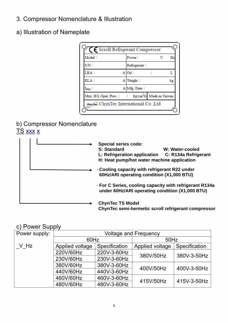
3. Compressor Nomenclature & Illustration
a) Illustration of Nameplate b) Compressor Nomenclature TS xxx x
Special series code: S: Standard W: Water-cooled L: Refrigeration application C: R134a Refrigerant H: Heat pump/hot water machine application
Cooling capacity with refrigerant R22 under 60Hz/ARI operating condition (X1,000 BTU) For C Series, cooling capacity with refrigerant R134a under 60Hz/ARI operating condition (X1,000 BTU)
ChynTec TS Model ChynTec semi-hermetic scroll refrigerant compressor
c) Power Supply Power supply: _V_Hz
Voltage and Frequency 60Hz 50Hz
Applied voltage Specification Applied voltage Specification 220V/60Hz 220V-3-60Hz 380V/50Hz 380V-3-50Hz230V/60Hz 230V-3-60Hz 380V/60Hz 380V-3-60Hz 400V/50Hz 400V-3-50Hz440V/60Hz 440V-3-60Hz 460V/60Hz 460V-3-60Hz 415V/50Hz 415V-3-50Hz480V/60Hz 480V-3-60Hz
6

4. Operating Envelopes and Limitations Compressor operating envelop depends on which refrigerant the compressor operates with. It indicates that within the specified saturated suction and discharge temperature the compressor can operate adequately for long term. It is the key element to ensure compressors operating life. If the suction temperature is too low, it might cause the problem for motor to be cooled properly. If the operating condensing temperature is too high, the motor is overloaded and it will shorten the operating life of compressor. The diagram below shows the operating envelopes of ChynTec scroll compressor for different refrigerants. S type W type
C type
-R22
L type H type
7

Remarks: 1. The envelope above is based on superheat at 5K. 2. Thermostat of motor winding is attached as the standard protector for each compressor. 3. The superheat for the suction line of the compressor is kept at 5~10 K. Maximum compressor
discharge temperature: 125°C. 4. To prevent liquid refrigerant from entering into compressor and cause loss of lubrication, the
recommended minimum discharge superheat is 15K. The discharge temperature should be maintained at least 15K higher than condensing temperature. Normally, discharge superheat is 25K for R134a, and 35K for R22 and R407C.
5. Due to R134a refrigerant molecule is tiny, special gasket should be applied for refrigerant passage in the system to prevent from refrigerant leakage after long period of operation. R407C and R404A are mixture of different refrigerants which contains R134a. The requirement is the same as R134a.
6. Lubricant POE oil for the model operates with refrigerant R-134a is hygroscopic. It will absorb the moisture in the air and cause damage to the system. Less than 1 hour exposure of POE oil to the air is strongly recommended.
7. The operating envelope above is marked by Dew point. R407C is a zeotropic mixture. R404A is an azeotropic mixture. There is a temperature glide in R407C and R404A. When mentioning about evaporating and condensing temperature, it is necessary to indicate DEW point or MEAN point. The figure below shows the definite difference between Mean and Dew temperature. The dotted line means isotherm not isobar. For R407C as an example, Mean point temperature is 2~3 lower than Dew point temperature.℃
8. When compressors operate within operating envelop, if lower body temperature is too low, excessive amount of liquid refrigerant may enter into compression chamber and cause damage to compressors. We can estimate the safety range of lower body temperature with respect to evaporating temperature as shown on figure below on the right. However, the highest temperature of lower body cannot exceed 90℃.
8

5. Mechanical Specifications: Standard Series, R22
Model TS165S TS185S TS210S TS250S TS280S TS310S
Capacity
60Hz
Speed (rpm) 3500 Displacement (m3/hr) 45.6 49.8 56.1 69.5 78.3 86.7 Cooling Capacity (kcal/hr)* 41,600 46,300 51,400 63,100 71,200 79,200 Power Input (kW) 13.9 15.4 17.2 21.1 23.6 26.3
50Hz
Speed (rpm) 2900 Displacement (m3/hr) 38.4 41.5 46.7 57.9 65.3 72.3 Cooling Capacity (kcal/hr)* 34,700 38,600 42,800 52,600 59,300 66,000 Power Input (kW) 11.6 12.8 14.3 17.6 19.7 21.9
Outline Scheme
Height, mm 589 701 Width, mm 389 427 Body flange diameter, mm 363 382 Net weight, kg 155 160 165 195 205 215 Installation hole, mm 14
Piping Suction pipe, mm 41.3 (1-5/8”) 41.3 (1-5/8”) Discharge pipe, mm 28.6 (1-1/8”) 34.9(1-3/8”) Electric hose diameter, mm 25.4
Motor
Lock rotor current (LRA)
60Hz 220V 261 304 401 460 545 545 380V 151 176 232 266 315 315 440V 131 152 201 230 273 273
50Hz 380V 125 146 192 220 261 261
Nominal current (Amp) *
60Hz 220V 44 49 53 66 73 81 380V 25 28 31 38 42 47 440V 22 25 27 33 37 41
50Hz 380V 22 24 26 32 35 39
Max current (I-max)*
60Hz 220V 51 56 63 77 85 96 380V 29 32 36 44 49 55 440V 26 28 32 39 43 48
50Hz 380V 25 27 31 37 41 46 Start-up method
Standard Standard direct start-up Optional None Y-Δ
Lubricant Standard SUNISO_4GS
Oil charged(Liter) 3 3 3 4 4 4 Standard Oil heater 100W 220V
Remark: 1. Cooling Capacity:The rated capacity under ARI operating condition. Measuring norm refers to
the regulations specified in CNS 11870B7273. 2. Nominal current:The nominal running current under ARI operating condition. Measuring norm
is as above. 3. Max. current:The maximum running current under the sufficiently cooling of motor.
9

10
Standard Series, R407C
Model TS165S TS185S TS210S TS250S TS280S TS310S
Capacity
60Hz
Speed (rpm) 3500 Displacement (m3/hr) 45.6 49.8 56.1 69.5 78.3 86.7 Cooling Capacity (kcal/hr)* 38,800 43,100 47,700 59,100 66,600 73,700
Power Input (kW) 13.9 15.4 17.0 21.1 23.8 26.3
50Hz
Speed (rpm) 2900 Displacement (m3/hr) 38.4 41.5 46.7 57.9 65.3 72.3 Cooling Capacity (kcal/hr)* 32,300 35,900 39,800 49,300 55,500 61,400
Power Input (kW) 11.6 12.8 14.2 17.6 19.8 21.9
Outline Scheme
Height, mm 589 701 Width, mm 389 427 Body flange diameter, mm 363 382 Net weight, kg 155 160 165 195 205 215 Installation hole, mm 14
Piping Suction pipe, mm 41.3 (1-5/8”) 41.3 (1-5/8”) Discharge pipe, mm 28.6 (1-1/8”) 34.9(1-3/8”) Electric hose diameter, mm 25.4
Motor
Lock rotor current (LRA)
60Hz 220V 261 304 401 460 545 545 380V 151 176 232 266 315 315 440V 131 152 201 230 273 273
50Hz 380V 125 146 192 220 261 261
Nominal current (Amp) *
60Hz 220V 44 49 54 66 73 82 380V 25 28 31 38 42 47 440V 22 25 26 33 37 41
50Hz 380V 21 24 27 32 36 40
Max current (I-max)*
60Hz 220V 49 54 61 75 84 92 380V 28 31 35 43 48 53 440V 25 27 31 38 42 46
50Hz 380V 24 26 30 36 41 45 Start-up method
Standard Standard direct start-up Optional None Y-Δ
Lubricant Standard CPI_CP-2931AW
Oil charged(Liter) 3 3 3 4 4 4 Standard Oil heater 100W 220V
Remark: 1. Cooling Capacity:The rated capacity under ARI operating condition. Measuring norm refers to
the regulations specified in CNS 11870B7273. 2. Nominal current:The nominal running current under ARI operating condition. Measuring norm
is as above. 3. Max. current:The maximum running current under the sufficiently cooling of motor.

11
Standard Series, R134a
Model TS110C TS125C TS130C TS160C TS185C TS200C
Capacity
60Hz
Speed (rpm) 3500 Displacement (m3/hr) 45.6 49.8 56.1 69.5 78.3 86.7 Cooling Capacity (kcal/hr)* 27,400 29,900 33,400 41,700 46,700 51,700 Power Input (kW) 9.4 10.3 11.5 14.3 16.1 17.8
50Hz
Speed (rpm) 2900 Displacement (m3/hr) 38.4 41.5 46.7 57.9 65.3 72.3 Cooling Capacity (kcal/hr)* 22,900 25,000 27,900 34,800 39,000 43,100 Power Input (kW) 7.8 8.6 9.6 11.9 13.4 14.8
Outline Scheme
Height, mm 589 701 Width, mm 389 427 Body flange diameter, mm 363 382 Net weight, kg 155 155 160 185 195 205 Installation hole, mm 14
Piping Suction pipe, mm 41.3 (1-5/8”) 41.3 (1-5/8”) Discharge pipe, mm 28.6 (1-1/8”) 34.9(1-3/8”) Electric hose diameter, mm 25.4
Motor
Lock rotor current (LRA)
60Hz 220V 261 261 304 401 460 460 380V 151 151 176 232 266 266 440V 131 131 152 201 230 230
50Hz 380V 125 125 146 192 220 220
Nominal current (Amp) *
60Hz 220V 30 33 37 45 51 56 380V 17 19 21 26 29 32 440V 15 17 19 23 26 28
50Hz 380V 15 16 18 22 25 27
Max current (I-max)*
60Hz 220V 42 47 52 64 71 80 380V 24 27 30 37 41 46 440V 21 24 26 32 36 40
50Hz 380V 21 23 26 31 35 39 Start-up method
Standard Standard direct start-up Optional None Y-Δ
Lubricant Standard CPI_CP-2931AW
Oil charged(Liter) 3 3 3 4 4 4 Standard Oil heater 100W 220V
Remark: 1. Cooling Capacity:The rated capacity under ARI operating condition. Measuring norm refers to
the regulations specified in CNS 11870B7273. 2. Nominal current:The nominal running current under ARI operating condition. Measuring norm
is as above. 3. Max. current:The maximum running current under the sufficiently cooling of motor.

12
Water-cooled Series, R22 Model TS165W TS185W TS210W TS250W TS280W TS310W
Capacity
60Hz
Speed (rpm) 3500 Displacement (m3/hr) 45.6 49.8 56.1 69.5 78.3 86.7 Cooling Capacity (kcal/hr)* 40,700 46,100 50,300 61,000 70,300 77,800 Power Input (kW) 10.3 11.6 12.7 15.6 17.5 19.3
50Hz
Speed (rpm) 2900 Displacement (m3/hr) 38.4 41.5 46.7 57.9 65.3 72.3 Cooling Capacity (kcal/hr)* 33,900 38,400 41,900 50,800 58,600 64,800 Power Input (kW) 8.6 9.7 10.6 13.0 14.6 16.1
Outline Scheme
Height, mm 589 701 Width, mm 389 427 Body flange diameter, mm 363 382 Net weight, kg 155 155 160 190 200 210 Installation hole, mm 14
Piping Suction pipe, mm 41.3 (1-5/8”) 41.3 (1-5/8”) Discharge pipe, mm 28.6 (1-1/8”) 34.9(1-3/8”) Electric hose diameter, mm 25.4
Motor
Lock rotor current (LRA)
60Hz 220V 261 261 304 401 460 460 380V 151 151 176 232 266 266 440V 131 131 152 201 230 230
50Hz 380V 125 125 146 192 220 220
Nominal current (Amp) *
60Hz 220V 33 39 42 51 56 61 380V 19 22 24 29 32 35 440V 17 20 21 26 28 31
50Hz 380V 17 19 21 25 27 30
Max current (I-max)*
60Hz 220V 46 51 56 68 77 84 380V 26 29 32 39 44 48 440V 23 26 28 34 39 42
50Hz 380V 22 25 27 33 37 41 Start-up method
Standard Standard direct start-up Optional None Y-Δ
Lubricant Standard SUNISO_4GS
Oil charged(Liter) 3 3 3 4 4 4 Standard Oil heater 100W 220V
Remark: 1. Cooling Capacity:The rated capacity under ET: 3℃, CT: 38℃, Subcooling:5K, Superheat:5K
operating condition. Measuring norm refers to the regulations specified in CNS 11870B7273. 2. Nominal current:The nominal running current under ET: 3℃, CT: 38℃. Measuring norm is as
above. 3. Max. current:The maximum running current under the sufficiently cooling of motor.

13
Refrigeration, L Series, R22 Model TS165L TS185L TS210L TS250L TS280L TS310L
Capacity
60Hz
Speed (rpm) 3500 Displacement (m3/hr) 45.6 49.8 56.1 69.5 78.3 86.7 Cooling Capacity (kcal/hr)* 25,200 27,800 30,700 38,500 42,800 47,400 Power Input (kW) 9.8 10.9 12.1 15.4 16.8 18.6
50Hz
Speed (rpm) 2900 Displacement (m3/hr) 38.4 41.5 46.7 57.9 65.3 72.3 Cooling Capacity (kcal/hr)* 21,000 23,200 25,600 32,100 35,700 39,500 Power Input (kW) 8.2 9.1 10.1 12.8 14.0 15.5
Outline Scheme
Height, mm 589 701 Width, mm 389 427 Body flange diameter, mm 363 382 Net weight, kg 155 160 165 190 200 210 Installation hole, mm 14
Piping Suction pipe, mm 41.3 (1-5/8”) 41.3 (1-5/8”) Discharge pipe, mm 28.6 (1-1/8”) 34.9(1-3/8”) Electric hose diameter, mm 25.4
Motor
Lock rotor current (LRA)
60Hz 220V 261 304 401 460 460 545 380V 151 176 232 266 266 315 440V 131 152 201 230 230 273
50Hz 380V 125 146 192 220 220 261
Nominal current (Amp) *
60Hz 220V 32 35 39 49 54 59 380V 18 20 22 28 31 34 440V 16 18 20 25 27 30
50Hz 380V 16 17 19 24 26 29
Max current (I-max)*
60Hz 220V 49 54 59 75 82 90 380V 28 31 34 43 47 52 440V 25 27 30 38 41 46
50Hz 380V 24 26 29 36 40 44 Start-up method
Standard Standard direct start-up Optional None Y-Δ
Lubricant Standard SUNISO_3GS
Oil charged(Liter) 3 3 3 4 4 4
Standard Oil heater 100W 220V
Shutoff Valve Intake/Out Shutoff Valve Remark:
1. Cooling Capacity:The rated capacity under ET: -10℃, CT: 40, Subcooling:5K, Superheat:5K operating condition. Measuring norm refers to the regulations specified in CNS 11870B7273.
2. Nominal current:The nominal running current under ET: -10℃, CT: 40℃. Measuring norm is as above.
3. Max. current:The maximum running current under the sufficiently cooling of motor.

14
Refrigeration, L Series, R404A Model TS165L TS185L TS210L TS250L TS280L TS310L
Capacity
60Hz
Speed (rpm) 3500 Displacement (m3/hr) 45.6 49.8 56.1 69.5 78.3 86.7 Cooling Capacity (kcal/hr)* 26,000 28,500 32,100 38,500 44,600 49,400 Power Input (kW) 11.4 12.3 13.9 17.5 19.4 21.4
50Hz
Speed (rpm) 2900 Displacement (m3/hr) 38.4 41.5 46.7 57.9 65.3 72.3 Cooling Capacity (kcal/hr)* 21,700 23,800 26,800 32,100 37,200 41,200 Power Input (kW) 9.5 10.3 11.6 14.6 16.2 17.8
Outline Scheme
Height, mm 589 701 Width, mm 389 427 Body flange diameter, mm 363 382 Net weight, kg 155 160 165 190 200 210 Installation hole, mm 14
Piping Suction pipe, mm 41.3 (1-5/8”) 41.3 (1-5/8”) Discharge pipe, mm 28.6 (1-1/8”) 34.9(1-3/8”) Electric hose diameter, mm 25.4
Motor
Lock rotor current (LRA)
60Hz 220V 261 304 401 460 460 545 380V 151 176 232 266 266 315 440V 131 152 201 230 230 273
50Hz 380V 125 146 192 220 220 261
Nominal current (Amp) *
60Hz 220V 37 39 44 56 59 66 380V 21 22 25 32 34 38 440V 19 20 22 28 30 33
50Hz 380V 18 19 21 27 29 32
Max current (I-max)*
60Hz 220V 51 56 63 78 85 94 380V 29 32 36 45 49 54 440V 26 28 32 39 43 47
50Hz 380V 25 27 31 38 41 46 Start-up method
Standard Standard direct start-up Optional None Y-Δ
Lubricant Standard CPI_CP-2931AW
Oil charged(Liter) 3 3 3 4 4 4
Standard Oil heater 100W 220V
Shutoff Valve Intake/Out Shutoff Valve Remark:
1. Cooling Capacity:The rated capacity under ET: -10℃, CT: 40℃, Subcooling:5K, Superheat:5K, operating condition. Measuring norm refers to the regulations specified in CNS 11870B7273.
2. Nominal current:The nominal running current under ET: -10℃, CT: 40℃. Measuring norm is as above.
3. Max. current:The maximum running current under the sufficiently cooling of motor.

15
Heat Pump, H Series, R22
Model TS165H TS185H TS210H TS250H TS280H TS310H
Capacity
60Hz
Speed (rpm) 3500 Displacement (m3/hr) 45.6 49.8 56.1 69.5 78.3 86.7 Heating Capacity (kcal/hr)* 44,400 49,300 54,800 68,000 75,700 84,200 Power Input (kW) 14.8 16.3 18.3 22.4 25.0 27.8
50Hz
Speed (rpm) 2900 Displacement (m3/hr) 38.4 41.5 46.7 57.9 65.3 72.3 Heating Capacity (kcal/hr)* 37,000 41,100 45,700 56,700 63,100 70,200 Power Input (kW) 12.3 13.6 15.3 18.7 20.8 23.2
Outline Scheme
Height, mm 589 701 Width, mm 389 427 Body flange diameter, mm 363 382 Net weight, kg 160 165 170 195 205 215 Installation hole, mm 14
Piping Suction pipe, mm 41.3 (1-5/8”) 41.3 (1-5/8”) Discharge pipe, mm 28.6 (1-1/8”) 34.9(1-3/8”) Electric hose diameter, mm 25.4
Motor
Lock rotor current (LRA)
60Hz 220V 304 401 401 460 545 545 380V 176 232 232 266 315 315 440V 152 201 201 230 273 273
50Hz 380V 146 192 192 220 261 261
Nominal current (Amp) *
60Hz 220V 47 51 58 70 77 85 380V 27 29 33 40 44 49 440V 24 26 29 35 39 43
50Hz 380V 23 25 28 34 37 41
Max current (I-max)*
60Hz 220V 54 59 68 82 90 101 380V 31 34 39 47 52 58 440V 27 30 34 41 45 51
50Hz 380V 26 29 33 40 44 49 Start-up method
Standard Standard direct start-up Optional None Y-Δ
Lubricant Standard SUNISO_4GS
Oil charged(Liter) 3 3 3 4 4 4 Standard Oil heater 100W 220V
Remark: 1. Cooling Capacity:The rated capacity under ET: 2℃, CT: 60℃, Subcooling:5K, Superheat:5K
operating condition. Measuring norm refers to the regulations specified in CNS 11870B7273. 2. Nominal current:The nominal running current under ET: 2℃, CT:60℃. Measuring norm is as
above. 3. Max. current:The maximum running current under the sufficiently cooling of motor.

6. Dimensions of Compressors TS165/185/210(S / W / H) TS110/125/130(C)
16
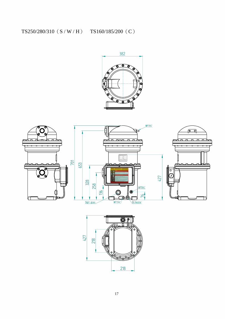
TS250/280/310(S / W / H) TS160/185/200(C)
17
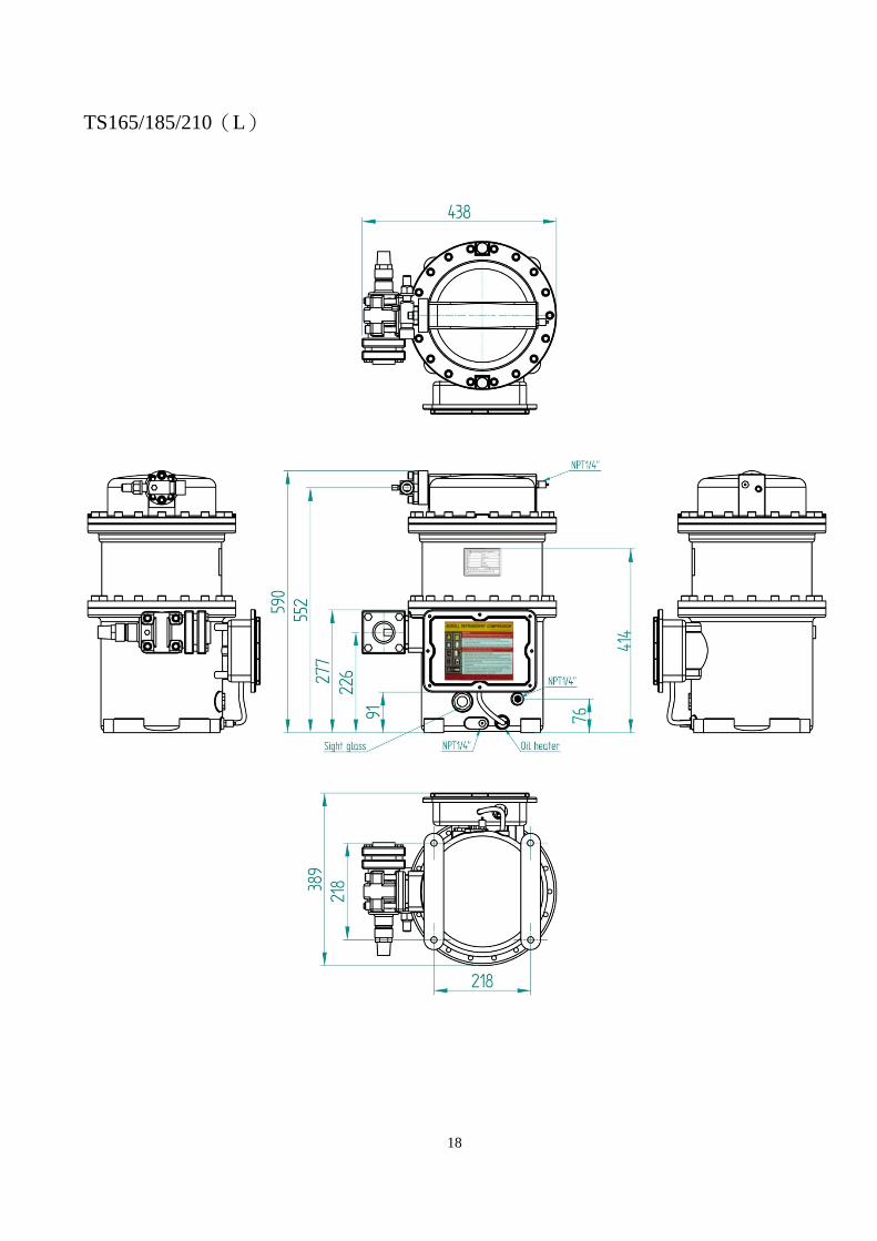
TS165/185/210(L)
18

TS250/280/310(L)
19
20
7. Electrical Design
1. Explanation to Electrical Current Compressor motor designs and illustrations are different among various compressor manufacturers. It often confuses HVAC system electrical control designers. Electrical data included in this manual are defined and specified as following: a. Operating Envelopes Normally, for air conditioning equipment, the system operating condition depends on both ambient temperature and interior temperature setting. The operating envelope (please refer to Section 4 of this manual) means the design envelop of compressor which maximum running envelope is certified by strict running tests. Do not exceed the envelope when setting the required operating point under the approved envelope of compressor, or it will reduce life of system and compressor.
b. Performance Table Performance table is the measured results of power input and refrigeration capacity for various points within the compressor operating envelope. The data are helpful for the HVAC system designers to know the maximum running current of system for choosing proper electrical components and overload protections for each individual system. c. Nominal Condition
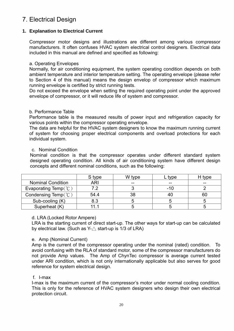
Nominal condition is that the compressor operates under different standard system designed operating condition. All kinds of air conditioning system have different design concepts and different nominal conditions, such as the following:
S type W type L type H type
Nominal Condition ARI -- -- -- Evaporating Temp(℃) 7.2 3 -10 2 Condensing Temp(℃) 54.4 38 40 60
Sub-cooling (K) 8.3 5 5 5 Superheat (K) 11.1 5 5 5
d. LRA (Locked Rotor Ampere) LRA is the starting current of direct start-up. The other ways for start-up can be calculated by electrical law. (Such as Y- start△ -up is 1/3 of LRA)
e. Amp (Nominal Current) Amp is the current of the compressor operating under the nominal (rated) condition. To avoid confusing with the RLA of standard motor, some of the compressor manufacturers do not provide Amp values. The Amp of ChynTec compressor is average current tested under ARI condition, which is not only internationally applicable but also serves for good reference for system electrical design. f. I-max I-max is the maximum current of the compressor’s motor under normal cooling condition. This is only for the reference of HVAC system designers who design their own electrical protection circuit.

2. Motor Electrical Connection Board Motor Electrical Connection Board Thermostat
Field Ground
21
FG 3 power-bolts terminal board Application:TS165/185/210(S/W/L/H)
TS110/125/130(C) U/V/W main power lines and motor coil thermostat connection as illustration, M8 bolt for field ground.
W U V
ThermostatField Ground
FG 3 power-bolts terminal board Application:TS250/280/310(S/W/L/H)
TS160/185/200(C) U/V/W main power lines and motor coil thermostat connection as illustration, M8 bolt for field ground.
W U
V
ThermostatField Ground
U FG
6 power-bolts terminal board Application:TS250/280/310(S/W/L/H)
TS160/185/200(C) U/V/W and X/Y/Z main power lines and motor coil thermostat connection as illustration, M8 bolt for field ground.
Z V
X W
Y

3. Start-up Options ChynTec compressors provide optional Y-Δ starting to customers. Y-Δ motor connects motor coil by Y connection during starting, therefore reducing voltage on coils to 1/√3 of input voltage and reconnects motor coil by Δ connection after starting. By doing so, we can decrease starting current through voltage drop, i.e., so-called voltage-drop starting. Y-Δ motor connection method is shown in the following motor wiring diagram: In Y connection, MCM and MCS are inductive while motor leads Z, X, Y are tied together as a neutral connecting as Y fashion. A few seconds later (1 sec is recommended), MCM and MCS become deductive. Around 40 ms later, MCM and MCD are inductive, it turns out Δ run connection. Please pay attention: After Y start, MCM and MCS are deductive for 40 ms and then MCM and MCD are inductive for Δ run. Within as transient as 40 ms, pseudo short circuit might occur due to inappropriate action of contactors, causing trip of compressors. When it occurs, we recommend usage of adjustable Y-Δ dedicated Timer or slightly lengthen time span for MCM and MCS deduction – MCM and MCD re-induction from 40 ms to 60 ms max directly in micro controller or PLC program. Because motor is not powered during Y-Δ shift, shorter Y-Δ shift span is suggested to prevent second start due to decreased rotation speed. However, if Y-Δ shift span is too short, aforementioned pseudo short circuit might occur. Characteristics of Y-Δ starting: a. Starting current in Y connection is 1/3 of lock rotor ampere. b. Starting torque in Y connection is 1/3 of lock rotor torque.
22

4. Electrical Wiring Diagram Please refer to the motor wiring drawing on the inside cover of terminal box.
23
24
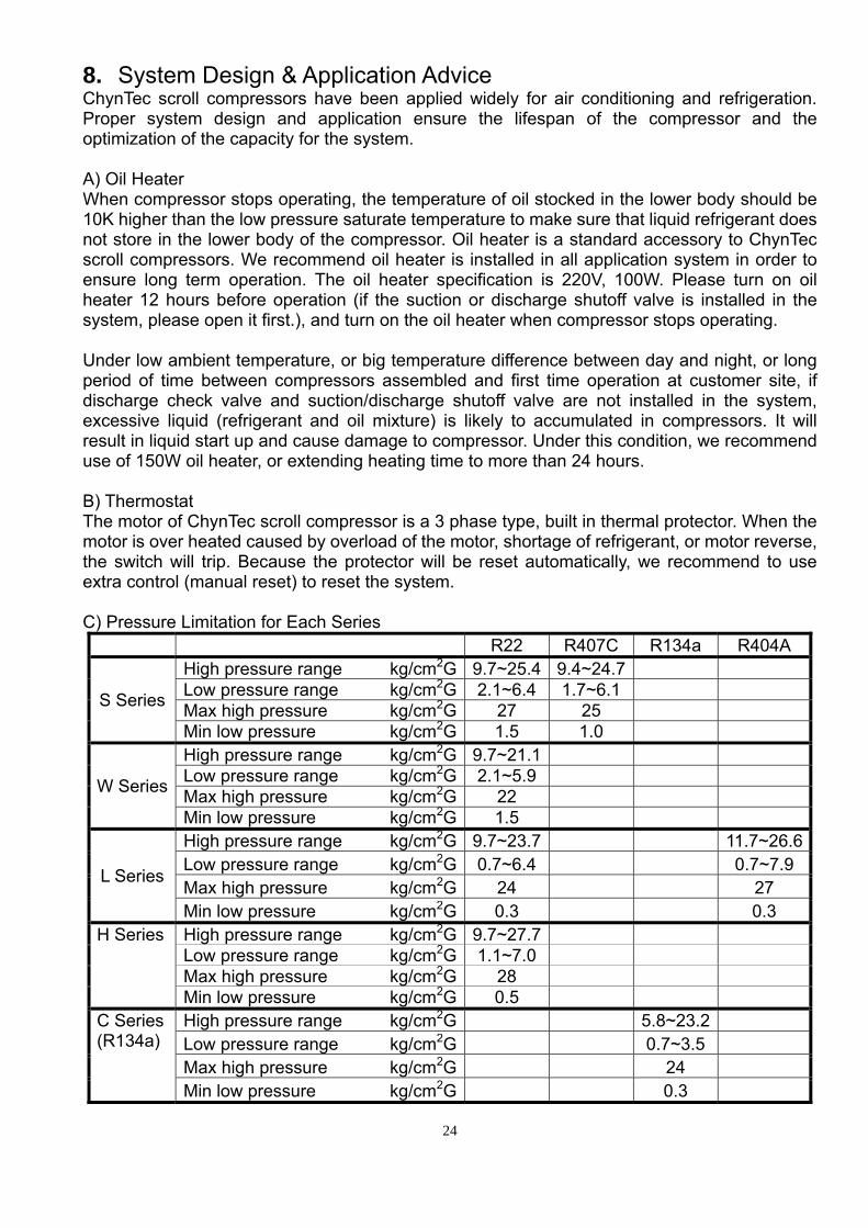
8. System Design & Application Advice ChynTec scroll compressors have been applied widely for air conditioning and refrigeration. Proper system design and application ensure the lifespan of the compressor and the optimization of the capacity for the system. A) Oil Heater When compressor stops operating, the temperature of oil stocked in the lower body should be 10K higher than the low pressure saturate temperature to make sure that liquid refrigerant does not store in the lower body of the compressor. Oil heater is a standard accessory to ChynTec scroll compressors. We recommend oil heater is installed in all application system in order to ensure long term operation. The oil heater specification is 220V, 100W. Please turn on oil heater 12 hours before operation (if the suction or discharge shutoff valve is installed in the system, please open it first.), and turn on the oil heater when compressor stops operating. Under low ambient temperature, or big temperature difference between day and night, or long period of time between compressors assembled and first time operation at customer site, if discharge check valve and suction/discharge shutoff valve are not installed in the system, excessive liquid (refrigerant and oil mixture) is likely to accumulated in compressors. It will result in liquid start up and cause damage to compressor. Under this condition, we recommend use of 150W oil heater, or extending heating time to more than 24 hours. B) Thermostat The motor of ChynTec scroll compressor is a 3 phase type, built in thermal protector. When the motor is over heated caused by overload of the motor, shortage of refrigerant, or motor reverse, the switch will trip. Because the protector will be reset automatically, we recommend to use extra control (manual reset) to reset the system. C) Pressure Limitation for Each Series
R22 R407C R134a R404A
S Series
High pressure range kg/cm2G 9.7~25.4 9.4~24.7 Low pressure range kg/cm2G 2.1~6.4 1.7~6.1 Max high pressure kg/cm2G 27 25 Min low pressure kg/cm2G 1.5 1.0
W Series
High pressure range kg/cm2G 9.7~21.1 Low pressure range kg/cm2G 2.1~5.9 Max high pressure kg/cm2G 22 Min low pressure kg/cm2G 1.5
L Series
High pressure range kg/cm2G 9.7~23.7 11.7~26.6Low pressure range kg/cm2G 0.7~6.4 0.7~7.9 Max high pressure kg/cm2G 24 27 Min low pressure kg/cm2G 0.3 0.3
H Series High pressure range kg/cm2G 9.7~27.7 Low pressure range kg/cm2G 1.1~7.0 Max high pressure kg/cm2G 28 Min low pressure kg/cm2G 0.5
C Series (R134a)
High pressure range kg/cm2G 5.8~23.2 Low pressure range kg/cm2G 0.7~3.5 Max high pressure kg/cm2G 24 Min low pressure kg/cm2G 0.3
High/Low pressure protector It is necessary for scroll compressors to install high pressure protector to protect compressors under the conditions of the block of fan, non-operative of cooling water in system. It is necessary to install low pressure protector to protect compressors under the conditions of shortage or leakage of refrigerant in system. How to setup the high/low pressure protector depends on the application and working condition. In general, high pressure protector should be lower than max high pressure listed above; low pressure protector should be higher than min low pressure listed above.
D) Low ambient temperature and minimum pressure difference The required minimum pressure difference between suction and discharge port of scroll compressor is 4~5 kg/cm2 to make sure enough back pressure to force orbiting scroll to sit on thrust bearing. If pressure difference below this required range, orbiting scroll will separate from thrust bearing and cause unwanted movement. To create enough pressure difference, it is necessary to maintain discharge pressure at certain level. Therefore, when compressor operates in low ambient temperature condition, the control on discharge pressure is very important. The noise level of compressor might be increased . E) Electric Voltage Requirement Stable power supply provides proper voltage to ensure stable and long term operation.
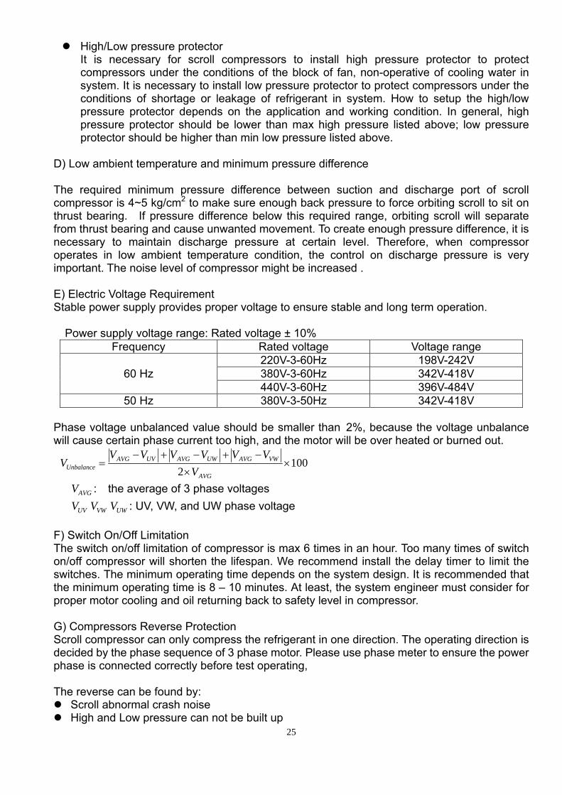
Power supply voltage range: Rated voltage ± 10% Frequency Rated voltage Voltage range
60 Hz 220V-3-60Hz 198V-242V 380V-3-60Hz 342V-418V 440V-3-60Hz 396V-484V
50 Hz 380V-3-50Hz 342V-418V Phase voltage unbalanced value should be smaller than 2%, because the voltage unbalance will cause certain phase current too high, and the motor will be over heated or burned out.
1002
××
−+−+−=
AVG
VWAVGUWAVGUVAVGUnbalance V
VVVVVVV
AVGV : the average of 3 phase voltages
UVV VWV UWV : UV, VW, and UW phase voltage F) Switch On/Off Limitation The switch on/off limitation of compressor is max 6 times in an hour. Too many times of switch on/off compressor will shorten the lifespan. We recommend install the delay timer to limit the switches. The minimum operating time depends on the system design. It is recommended that the minimum operating time is 8 – 10 minutes. At least, the system engineer must consider for proper motor cooling and oil returning back to safety level in compressor. G) Compressors Reverse Protection Scroll compressor can only compress the refrigerant in one direction. The operating direction is decided by the phase sequence of 3 phase motor. Please use phase meter to ensure the power phase is connected correctly before test operating, The reverse can be found by:
Scroll abnormal crash noise High and Low pressure can not be built up
25

We recommend install the power relay on system to ensure the normal operation. H) Discharge Temperature Limitation We recommend install temperature protector on the piping around 15 cm off discharge port to limit the max discharge temperature. The cutoff temperature is set at 125℃. Our optional accessory of discharge temperature protector cutoff temperature is 125℃ and the reset temperature is 105℃. I) Minimum Superheat at Suction Port To prevent excessive liquid refrigerant from entering into compression chamber directly, the recommended lowest suction superheat is 5K. The superheat of compressor should be maintained at 5-15K. J) Minimum Superheat at Discharge Port To prevent liquid refrigerant from entering into compressor and result in loss of lubrication, recommended minimum superheat at discharge port is 15K. (Discharge temperature is at least 15K higher than condensing temperature.) Normally, the discharge superheat is 25K for R134a, 35K for R22 and R407C. K) Oil Level Exam When the compressor operates stably, please make sure there is no liquid refrigerant stocked at the lower body of compressor, and the oil level should be above 1/2 of the sight glass and below upper limit shown in the right figure. You can also check the oil level immediately after the compressor shut down. At this moment, the oil level should be above 1/2 of the sight glass. L) Notice of Pump Down a. The damage caused by incorrect operation of pump down shall render the warranty void. b. Stop the compressor immediately if any abnormal noise noticed during pump down process. c. The low pressure limitation is 0.5(Kg/cm2.G). The time limitation of pump down is 15
seconds. Either condition sets up, stop the compressor immediately. M) Suction Port Liquid Injection When operate in air-cooled heat pump application under heavy loading working condition, or low temperature refrigeration application under high compression ratio working condition, the motor is likely over-heated, and the discharge temperature will exceed the max discharge temperature limit. These will shorten the operating lifespan of compressors. Suction port liquid injection device is to install a solenoid valve and an expansion vale between liquid line and compressor suction port to introduce part of liquid refrigerant into compressor. This is to utilize the latent heat of liquid refrigerant to cool down motor coil temperature, and compression chamber temperature to ensure adequate long term operation and safety of compressors.
26

It is recommended to install suction port liquid injection device when discharge temperature is higher than 125℃ for certain system application. The device includes high temperature expansion valve and solenoid valve, as shown in the right figure. The setting temperature of solenoid valve is at 115℃. When discharge temperature reaches 115℃, solenoid vale will be opened; and discharge temperature drops to 95℃, solenoid valve will be closed again. If the discharge temperature rises higher than 125℃ even the solenoid valve has been opened, the discharge temperature protector must be tripped to protect compressor. High temperature expansion valve equipped with a temperature sensor to detect discharge temperature and control the flow of refrigerant accordingly to utilize liquid refrigerant to cool down discharge temperature.
27
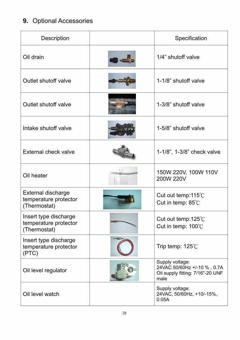
9. Optional Accessories
Description Specification
Oil drain
1/4” shutoff valve
Outlet shutoff valve
1-1/8” shutoff valve
Outlet shutoff valve
1-3/8” shutoff valve
Intake shutoff valve
1-5/8” shutoff valve
External check valve
1-1/8”, 1-3/8” check valve
Oil heater 150W 220V, 100W 110V
200W 220V
External discharge temperature protector (Thermostat)
Cut out temp:115℃ Cut in temp: 85℃
Insert type discharge temperature protector (Thermostat)
Cut out temp:125℃ Cut in temp: 100℃
Insert type discharge temperature protector (PTC)
Trip temp: 125℃
Oil level regulator Supply voltage:
24VAC 50/60Hz +/-10 % , 0.7A Oil supply fitting: 7/16"-20 UNF male
Oil level watch Supply voltage:
24VAC, 50/60Hz, +10/-15%, 0.05A
28

PTC motor protector Power supply:
AC 50/60Hz 24V-15%+10% AC 50/60Hz 115-120/230-240V-15%+10%
PTC motor protector (with phase sequence relay)
Power supply: AC 50/60Hz 115-120/230-240V-15%+10% 3VA Phase sequence relay: 3 AC 50/60Hz, 200…575±10%
Suction filter Suction filter
Oil recommends
Refrigerant Product Series
Mineral oil POE oil 4GS 3GS Icematic-299 CP-2931AW RL 32H
R22
S Standard Optional W Standard Optional L Standard H Standard Optional
R134a C Standard Optional R407C S Standard Optional R404A L Standard Optional
Specification of refrigeration oil:
Item Specification 4GS 3GS CP-2931AW Icematic-299 RL321 Viscosity @40℃
@100℃ (mm2/s) 54.9 5.97
29.5 4.31
32.3 5.71
55.5 5.94
32.55.8
2 Specific Gravity @15℃ 0.915 0.909 0.982 0.92 0.9773 Water Content (ppm) 20 20 <100 45 <404 Pour Point ( )℃ -35 -40 -51 -36 -46 5 Flash Point (℃), C.O.C. 188 178 257 183 2586 Acid Number (Mg KOH/g) 0.01 0.01 <0.05 0.05 0.02
Remark: 1. POE code: CP-2931AW. This POE oil is for compressor operates with refrigerant R407C,
R134a, R404A, R410A, etc. 2. POE oil is very hygroscopic. Less then 1 hour exposure to the air is strongly recommended
after the intake and outlet of the compressor is unsealed. 3. When the original refrigeration oil of the compressor and system unit is replaced by POE oil,
the remaining mineral oil must not exceed 3% to assure smooth long term operation.
29

10. Maintenance
1. All parts of compressor are recyclable, and shall be recovered, reused and/or disposed of properly in connection with maintenance, repair and scrapping.
2. Maintenance notices: a) Personal safety concern; b) Be careful of the damage to environment and facility; c) Be sure the system kept in good operating condition; d) Consider the maintenance space at the system design and installation stage; e) Must exam the leakage of refrigerant or oil after maintenance; f) Reduce the operational cost of maintenance.
3. When change the type of refrigerant operates with the system, the following notices shall be taken in account: a) Make sure which type of refrigerant the system can operate with; b) Examine all materials used in the system to ensure they are compatible with the
replaced refrigerant; c) Verify the possibility of exceeding the allowable pressure; d) Verify the motor capacity; e) Pay attention to the refrigerant classification; f) Prevent mixture of residual refrigerant and residual oil.
4. Maintenance Period Recommendation
100 1000 10000 20000 30000
Out looking ▲ ▲ ▲ ▲ ▲ Electric insulation ▲ ▲ ▲ Refrigeration oil ◎
Oil level ▲ ▲ ▲ ▲ ▲ Noise / Vibration ▲ ▲ ▲ ▲ ▲
Bearing ◎
Hour Item
▲Check / ◎ Change Remark: a) Besides the periodical check listed above for electricity insulation, the insulation condition
needs to be checked annually before operation after long period of shutting down. b) If the abnormal noise/vibration is noted, please contact ChynTec immediately for technical
support. c) The pressure test and leakage test are required after compressor repairing. d) When the change of bearing is necessary, please change the whole bearing set. e) Unless instructions and procedures are followed, and services conducted by authorized
personnel, any damage caused will render the warranty void, and repairs will be on owner’s expense.
30

11. Dimensions of Intake and Outlet Flange TS Model Intake Flange
31

TS165/185/210(S/W/L/H) TS110/125/130(C) Outlet Flange
32

TS250/280/310(S/W/L/H) TS160/185/200(C) Outlet Flange
33