semi-parametric color reproduction method for optical see...
TRANSCRIPT

Semi-Parametric Color Reproduction Method for OpticalSee-Through Head-Mounted Displays
Yuta Itoh, Student Member, IEEE, Maksym Dzitsiuk,Toshiyuki Amano, Member, IEEE, and Gudrun Klinker, Member, IEEE
(a) (b) (c)
Fig. 1. A demonstration of the color reproduction problem in OST-HMDs and a result of our correction method. (a) A physical scenecaptured by a user-perspective camera. (b) A captured image of (a) rendered on a consumer OST-HMD with an opaque background.(c) A captured image of a pre-processed image of (a) displayed on the HMD. Rendering (a) on the display causes chromaticallydistorted image (b), which is undesirable for natural AR experiences. The corrected image (c) reproduces the original color better,thus potentially provides better color constancy in visual-processing AR applications.
Abstract— The fundamental issues in Augmented Reality (AR) are on how to naturally mediate the reality with virtual content asseen by users. In AR applications with Optical See-Through Head-Mounted Displays (OST-HMD), the issues often raise the problemof rendering color on the OST-HMD consistently to input colors. However, due to various display constraints and eye properties, it isstill a challenging task to indistinguishably reproduce the colors on OST-HMDs. An approach to solve this problem is to pre-processthe input color so that a user perceives the output color on the display to be the same as the input.We propose a color calibration method for OST-HMDs. We start from modeling the physical optics in the rendering and perceptionprocess between the HMD and the eye. We treat the color distortion as a semi-parametric model which separates the non-linear colordistortion and the linear color shift. We demonstrate that calibrated images regain their original appearance on two OST-HMD setupswith both synthetic and real datasets. Furthermore, we analyze the limitations of the proposed method and remaining problems ofthe color reproduction in OST-HMDs. We then discuss how to realize more practical color reproduction methods for future HMD-eyesystem.
Index Terms— OST-HMD, color replication, color calibration, optical see-through display.
1 INTRODUCTION
One of the most fundamental issues in Augmented Reality (AR) is howto mediate virtual contents and physical scenes consistently so thatthe contents appear as realistic as possible. In AR applications withan Optical See-Through Head-Mounted Display (OST-HMD), the dis-play imposes virtual contents into a user’s field of view (FoV) directly.Since the user perceives the contents together with the physical worldas a reference in which the contents are registered, the user will imme-diately exclude the virtual contents if their appearance is implausiblecompared to the observed reality in the same view.
We believe that a future, ultimate OST-HMD is capable of provid-
• Yuta Itoh is with the Department of Informatics at Technical University ofMunich. E-mail: [email protected]
• Maksym Dzitsiuk is with the Department of Informatics at TechnicalUniversity of Munich. E-mail: [email protected]
• Toshiyuki Amano is with the Faculty of Systems Engineering at WakayamaUniversity. E-mail: [email protected]
• Gudrun Klinker is with the Department of Informatics at TechnicalUniversity of Munich. E-mail: [email protected]
ing users with visual stimuli that are indistinguishable from the real-ity. However, current OST-HMDs can not realize such truly naturalAR experiences due to various reasons. The key question is how torender virtual contents consistently with reality. In other words, anOST-HMD has to present visual information adapted seamlessly to thereality in various aspects: temporally, spatially, and visually. Amongthem, the visual consistency is the focus of this paper.
In AR applications, a visually-consistent OST-HMD system mustcreate visual stimuli as exactly as specified: if we input a digital RGBcolor, the display should reproduce a color which an eye perceives asthe same color (Fig. 1). This truthful color reproduction is a funda-mental requirement for any OST-HMD system so that they can furtherbenefit from related visual processing techniques in AR, e.g. render-ing with global illumination [1], appearance control of physical objects[2, 3], and vision enhancement [4].
In current HMDs, this is not the case. For example, if a system triesto render a virtual, white spotlight on a real object while the displayhas bluish color distortion, then the virtual light appears bluish insteadof pure white even if the system takes the scene illumination and theradiometric property of the object into account. This is analogous tothe spatial registration between an OST-HMD and the real world: evenif the 3D structure of the world is perfectly known, virtual contentsstill appear misaligned if the calibration between an OST-HMD and auser’s eye position is inaccurate.
Note that the semitransparent medium of an OST-HMD also causes

𝑒𝑊(𝜆)
r𝐶(𝜆)
d𝐶 =RGBg𝐶 g𝐻
−1
e𝐻(𝜆)
LCD, DLP, etc.
𝑚𝐻(𝜆)
Optical
Medium
𝑚𝑊(𝜆)g𝐸(𝜆)
r𝐸(𝜆)
d𝐸
d′𝐸
OST-HMDWorld camera
𝑒′𝐻 𝜆
Eye (camera)Scene
Path A: Display calibration (this work, uses synthetic d𝑪)
Path B: Calibration between “cameras” (needs measured d𝑪)
Visually consistent rendering
(for measured d𝑪)
Fig. 2. An overview of color calibration problems on an OST-HMD system. Our display calibration problem is to calibrate the HMD and the eyecamera (Path A). In this case dC is synthetic color. As introduced in the evaluation section, a scene image taken by a world camera is needed tomeasure visual consistency of AR rendering (Path B and the text on the right of the diagram). In this case dC is physically measured color.
a color blending problem between the background scene and a dis-played image. However, this paper does not focus on this issue whichcan be solved by introducing an opaque layer in the display design[5, 6]. Once the display color is correctly calibrated, the blendingproblem can be solved by subtracting a measured background colorfrom a target color to be rendered [7].
The other causes of the color discrepancy in OST-HMDs are mainlytwofold: light absorption by the imperfect optical medium of the HMDand lossy digital-analog color conversion between the HMD and aneye.
OST-HMDs have complex optics that propagates a virtual imagefrom the display image source to a user’s eye by refracting the lighttypically via beam-splitting mirrors or free-form prisms [8, 9] (Path Ain Fig. 2). Since the user sees the virtual image through these semi-transparent optical media, the spectrum of the light that reaches to theuser’s eye is not necessarily identical to the original one emitted fromthe image source [10].
The rendering/perception process of the HMD-eye system, i.e thecolor transfer from the light source of the HMD to the photoreceptorsof a human eye, causes another color distortion. When the HMD ren-ders a digital color dC, the display emits the data as a physical lightwith analog spectrum. The light is then re-converted to color databy the photoreceptors of an eye (and our brain) which has a differentspectral response than that of the image sensor. Since these analog-digital color conversions inevitably lose information, just rendering atarget color on the HMD can not reproduce the same color at the eye.
These two reasons combined, estimating color distortions in OST-HMDs becomes a challenging task. A naive way is to create a look-uptable (LUT) between the input and the actually perceived color. Whilethe calibration based on this approach is simple, it is costly in memorysize and does not consider any prior knowledge, i.e. physical phenom-ena of the display system. Incorporating a physical model would giveus room to extend the calibration model by updating it in the future.
We focus on the color reproduction problem while featuring thecolor processing flow in HMD-eye systems (Path A in Fig. 2). Wepropose a semi-parametric color calibration method that makes useof the knowledge from projector-camera systems (PCS) and ordinarydisplay calibration techniques. We learn the color response between auser-perspective camera (a camera located at the eyepoint to acquiredata and calibrate) and each color channel of the display.
A display in general has a non-linear relationship between the inputdigital color and the produced light intensity. This relationship is typi-cally observed as a smooth curve called the gamma curve. Our methodlearns a color mapping function as the combination of the correctionof this gamma curve and a linear conversion of color channels witha post-scaling adjustment. More importantly, we provide a thoroughanalysis of the current color reproduction setup including limitations,research issues, and possible solutions for indistinguishable color vi-sualization in OST-HMD systems.
ContributionsOur main contributions are the following:
• We propose a semi-parametric color calibration method whichincorporates the optical properties of OST-HMD systems
• We provide a thorough evaluation of the proposed method in-cluding limitations and discussions for more practical color re-production in HMD-eye system.
We also state a general color reproduction problem in OST-HMDs ontop of color models in PCS and display calibration fields.
2 RELATED WORK
As the HMD-eye system is analogous to the PCS, this section elab-orate these problems along works of PCS. We first introduce visual-processing AR applications that are potentially transferable to OST-HMD systems; yet need an accurate color reproduction to do so. Wethen overview color calibration research in display systems includingPCSs and OST-HMDs.
2.1 Visual Consistency in AR ApplicationsIn video-based AR, various works aim to enhance the realism of ARrendering. Their methods implicitly stand on accurate color repro-duction of a display, which is rather easy to achieve on video-basedsystems by integrating virtual contents directly into captured images.Lee and Woo [11] propose a method which reflects the illuminationof a scene into the rendering of virtual objects by referring to the re-flection on a fiducial marker. Knorr and Kurz [12] estimate a sceneillumination from the reflection of light on human faces, and realizecoherent AR visualization with the estimated illumination. Fischer etal. [13] incorporate the sensor noise and the motion blur of a camerawhen rendering virtual objects by blurring and adding synthetic noiseon an output image.
In spatial AR, various systems target on augmenting the appearanceof physical objects. Menk and Koch [14] present a visualization sys-tem which reproduces desired input color on a physical, miniature 3Dcar model by a PCS. Amano and Kato [2] propose a dynamic PCSsystem which controls the appearance of scene objects via dynamiccamera projector feedback.
If we want to transfer these visual-processing techniques to OST-HMD systems, assuring the color reproducibility will be a critical is-sue. Our recent work on a vision enhancement for defocus correctionwith OST-HMDs [4] is also an example that requires perfect color re-production between the scene and a displayed enhancement image.The next section elaborates works related to the color constancy indisplay systems including the OST-HMDs.
2.2 Color Reproduction in Display SystemsSince the popularization of projectors, printers and digital cameras, re-searchers have tackled the topic of calibrating colors for such imagemedia [15, 16, 17, 18, 19, 20, 21, 22]. The OST-HMD technology,however, still lacks elaborate study on color reproduction. Since thisproblem on OST-HMDs is significantly cross-correlated with that for
other types of displays – especially PCS, we survey existing color re-production methods in the related display technologies.
We can see a general color reproduction problem as the following:given a target color dE perceived by an eye E, and some prior knowl-edge θ of the display and the environment, we want to find an inputcolor for the display as dC = f (dE ,θ), where f conceptually representsthe inverse of image rendering process from a display to the image dE
perceived by the eye (or a camera).Intuitively speaking, f is a color mapping between two images.
Note that dC and dE may have some constraints due to their sensorssuch as dynamic range limitation. Depending on how we define f , ex-isting methods can be classified into a non-parametric, a parametric,and a semi-parametric approaches.
2.2.1 Non-Parametric ApproachIn non-parametric methods, f is locally defined by each target colorvalue dE . The most non-parametric approach is to use LUTs [20, 14,23, 10, 18]. LUT-based methods are purely non-parametric since eachtarget color dE is mapped to the corresponding input color dC inde-pendently. In general, these methods are not suitable for direct colormapping: unlike with projectors and printers, OST-HMDs are oftenbased on mobile processors and graphic chips. Such systems thus cannot perform huge number of transformations with an acceptable framerate when traversing big LUTs (see Sec. 3 for a LUT size estimate).Since the LUT method uses pixel-to-pixel correspondences, it is proneto noise.
Hincapié-Ramos et al. [10] propose an LUT-based approach forprojectors that is further developed to be applicable for color correc-tion on OST-HMDs at run-time [23]. This method suggests splittingthe entire CIE Lab color space into bins of similar colors which is fol-lowed by building a LUT between target and displayed colors. Thelater work also proposes an optimization for a search in the LUT andimplementation of the algorithm as a GPU shader program that can beused in real time.
Note that the above methods do not incorporate prior knowledge θ .Our work is targeted at the same problem, but with a different approachwhich is derived from the physical model of the process.
Porikli [21] presents an inter-camera color correction method,which learns a LUT based on the correlation between training colorsamples {dC} taken by a source camera and {dE} taken by a targetcamera, and the method aims to learn the change of sensor responsesbetween both cameras. Kagarlitsky et al. [24] extend the correlationapproach by incorporating image segmentation to apply the mappingfor local image regions that possibly have different lighting conditions.
2.2.2 Parametric ApproachIn parametric methods, f is defined within a set of functions that can beparametrized by some variables. Our eyes or cameras perceive colorby trichromatic photoreceptors or sensors. Displays normally take 3DRGB input values. Therefore, f is often modeled as a 3-by-3 matrix M,and the problem becomes how to estimate this linear mapping betweendC and dE .
A well-known model is the von-Kries adaptation [25], also calleddiagonal correction [26], where each color channel intensity value islinearly scaled by a multiplicative factor. This does not hold for OST-HMDs as well because of the assumption of the linear color response[19]. In Sec. 5 we reconfirm empirically that commercial OST-HMDsalso have this non-linear response to be corrected.
Reinhard et al. [27] determine M by performing a histogram matchto transfer colors from one image {dC} to another {dE}. This approachis purely image-oriented and does not consider the physical model ofdisplays. Their method does not consider the gamma since the effectsis often negligible in their inter-image color correction setup.
2.2.3 Semi-Parametric ApproachThe nuisance of the color reproduction on displays is that the ren-dering process induces various non-linear effects such as the gammacurve. These non-linear effects are hard to handle with simple para-metric functions while they are computationally efficient. Although
the non-parametric approach is capable of handling the non-linearity,it can be computationally expensive and can require a huge memoryspace.
To get benefits from both methods, one can consider combining anon-parametric and a parametric function. A common way is to firstcorrect the gamma curve of the projector response. Nayar et al. [28]propose a color correction method for PCSs by modeling the imagingprocess of PCSs as the combination of a linear, color-mixing matrixand non-linear radiometric responses per color channel. Menk andKoch [14] also propose a similar method by modeling the distortionas the combination of 1D intensity gamma distortion and 3-by-3 colorconversion matrix, in addition to the scene illumination θ as a functionof the camera position.
In this work, we follow a semi-parametric approach. We aim tomodel the color distortion following the actual optical rendering pro-cess of OST-HMDs similar to [28]. Our calibration procedure exam-ines the color response of each color channel of the image source ofan OST-HMD, and then estimate the linear parameters and non-linearfunctions of the model.
3 METHOD
For OST-HMDs, virtual objects are presented next to physical objectsexisting both within the FoV of the HMD and outside of it (in the pe-ripheral viewing range of the user). For these displays, it is critical thatadded virtual objects blend perfectly into such physical environment.
To test such situations, it is not enough to merely display and eval-uate the color properties of synthetic virtual objects (Path A in Fig 2).They need to be seen in physical context.
A practical approach for such comparison is to generate virtual ob-ject data via photographs of the physical world (by a world camera)and to compare the displayed colors of such an image (as seen by auser-perspective camera) with the original color image itself (the righttext in Fig 2).
In other words, the goal of the color calibration can be separatedinto two problems: calibration between an OST-HMD and an eye (dC
and dE , Path A), and between a world-looking camera and an eye cam-era (dC and d′E , Path B).
This paper focuses only on the former problem (Path A). The lattercan be tackled independently from the former. Our evaluation alsocompares dE and d′E with a physically measured dC to see the potentialperformance of our calibration for AR rendering setups. For this, aswe later explain, our exemplifying setup assumes that the Path B isnegligible since we use a single camera as the world and eye camera.
In the following, we first model a general color rendering processof the HMD-eye system, then we introduce our calibration approach.
3.1 Notations
Ordinary lower-case letters denote functions and scalar values suchas a radiometric response function e(λ ) with the scalar wavelength λ .Bold lower-case letters denote multi-valued functions and vectors suchas an RGB sensor response function r(λ ) and an RGB color triplet d.Upper typewriter letters denote matrices such as M. We use (·)T forthe transpose of vectors and matrices, (·)−1 for the inverse of func-tions/matrices, and ◦ for the element-wise product of arrays. Upper-case black-bold letters denote sets such as the set of non-negative realnumbers R≥0 and of integers N. We assume digital colors ranged from0 to 255 and denote the integer set as N[0,255].
3.2 Radiometric Model of OST-HMDs
We first introduce a general radiometric model of an OST-HMD setup.Later in the next section, we derive a simplistic model out of the gen-eral model so that we can for now handle with our OST-HMD setup.For a more practical calibration, we cannot avoid working on the gen-eral model, which is still a challenging task with existing HMD tech-nologies. Note that the radiometric model of OST-HMDs has a closerelationship to that of PCSs.
3.2.1 Display-eye calibration | Path A in Fig. 2Given an input digital color dC ∈ N3
[0,255], the display produces a three-dimensional spectral distribution as a function of a wavelength:
eH(λ |dC) ∈ R3≥0, (1)
where each element of eH corresponds to each RGB filter of the displaylight source. We assume that each element of the function is indepen-dent from its channel brightness:
eH(λ |dC) = g−1H (dC)◦ eH(λ ), (2)
where g−1H (·) : N3
[0,255]→R3≥0 is the brightness of the display which mod-
ulates the base spectral distribution of the display: eH(·) : R≥0→ R3≥0.
Under this model, the display emits the following light:
e′H(λ ) : =3
∑k=1
[eH(λ |dC)]k = g−1H (dC)
TeH(λ ) ∈ R≥0. (3)
The eye perceives the display light e′H(λ ). Although modeling humancolor vision is yet another challenging topic, let us for now considera user perspective camera E as a replacement of an eye. Let gE(·) :R3 → N3
[0,255] be the gamma function of the camera. Then the cameraoutputs
dE : = gE
(ˆe′H(λ )mH(λ )rE(λ )dλ
)(4)
= gE
(ˆ (g−1
H (dC)TeH(λ )
)mH(λ )rE(λ )dλ
), (5)
where mH(λ ) represents an intensity loss of the light when it propa-gates a light path from the image source to the camera sensor throughthe medium, and rE(λ ) is an efficiency function of the camera sensor.
Note that the digital color vector dC is the only parameter we cancontrol as an input of Eq. (3). A naive way to find the best dC is a bruteforce approach where we display all possible color combinations of dC
and measure resulting dE . Then we create a huge look-up table from dE
to dC. This non-parametric, discrete approach requires extra memoryand calibration time. For example, if we use 8-bit RGB color model,the table size becomes about 50MB (≈ 2563 ∗8∗3 bit) and recordingall color responses would take more than 6 days even if we can captureeach color in 30Hz non-stop.
Hincapié-Ramos et al. [23] extended this approach and proposeda real-time method by binning the table entries in a CIE Lab colorspace to compress the overall table size while keeping the matchingquality reasonable. Unlike these pure non-parametric approaches, wefurther investigate the physical model of OST-HMDs to derive a sim-pler model. We believe modeling the system based on its physicalmechanism leaves us more room to improve the model in the future.
Since g−1H (dC) is independent from λ , we reformulate Eq. (5) as
dE = gE
(ˆ (mH(λ )rE(λ )eH(λ )
T)
dλ︸ ︷︷ ︸=:M
g−1H (dC)
)= gE (Mg−1
H (dC)) ,
(6)where M ∈ R3×3 is a constant, color conversion matrix. The colordistortion is now modeled as a semi-parametric model which consistsof two non-linear functions {gE ,g−1
H } and the linear matrix.We employ the following relationship between the target color dE
and the input color dC,
dE = gE (Mg−1H (dC)) , (7)
dC = gH
(M−1g−1
E (dE)). (8)
Our problem is now how to estimate gH , M−1, and g−1E from training
data (dC,dE). Before explaining this, we briefly introduce the conceptof visually consistent AR rendering in the next section.
3.2.2 Visually consistent AR rendering | Fig. 2 Path B and rightIn AR applications with OST-HMDs, a user sees the physical worldand virtual image in the same FoV. If the light from the world andthat from the display coincide, then an observer can not distinguish, interms of color, if a perceived color is from the display or directly fromthe world. However, this is unlikely to occur in practice – the imagesensor of a camera and the photoreceptors of an eye have differentresponses, thus the image source of an HMD can not reproduce theoriginal light spectra by mere, typically, three RGB light channels.
Fortunately, our cone cells (and image sensors) cannot distinguishlight with different spectra if they cause the equivalent amount ofelectrical charge in the cells – the phenomena which is known asmetamerism, thus we consider perceived color spaces.
Consider a camera C placed in the world W (Fig. 2 Path B). Thecamera captures light from the world with a spectral distribution eW (·) :R≥0→ R≥0, then converts the light into an RGB vector:
dC := gC
(ˆeW (λ )rC(λ )dλ
)∈ N3
[0,255], (9)
where rC(·) : R≥0→R3≥0 is an efficiency function of the camera sensor
and gC(·) : R3 → N3[0,255] is a sensor gamma function which converts
analog signals to digital values.The eye camera sees the color of the real world as:
d′E := gE
(ˆeW (λ )mW (λ )rE(λ )dλ
), (10)
mW (λ ) represents an intensity loss due to the medium of the OST-HMD. Note that mW (λ ) is not necessarily same as mH(λ ).
Overall, visually consistent AR rendering requires dE and d′E to becloser to each other (Fig. 2 right).
3.3 Assumptions on OST-HMD SetupsWe use several assumptions in our calibration. In this work, we use auser-perspective camera instead of an actual human subject. Thus thiswork focuses more to understand the mechanism of OST-HMDs in thecontext of the color reproduction problem. We also use a single camerafor both the world camera and the eye camera and let the camera seethe world behind OST-HMDs to ignore the material distortion mW (λ ).Thus, we assume dC = d′E .
Given that we use an industrial camera with calibrated gamma, weassume that the user-perspective camera has a linear camera gammavalue as a diagonal matrix DE ∈ R3×3
≥0 instead of gE . Now Eq. (8) and(7) are written as
dE = DEMg−1H (dC)+ c, (11)
dC = gH (M−1D−1
E (dE − c)) . (12)
We also added a 3D constant vector c ∈ R3≥0 to the projected color.
Because a display image source produces light even when the inputcolor is completely black – i.e., the black offset [19]. Since the non-linearity of the model is represented by g−1
H , our calibration strategy isto first remove this non-linearity by learning non-linear, gamma cor-rection functions, then to learn an affine transformation between thetarget and linearized input colors.
3.4 Semi-Parametric Color CalibrationWe are now ready to explain our calibration method. For the sakeof easier understanding, we will show some real measurements takenfrom an OST-HMD setup introduced later in the experiment section.
To be able to reproduce colors of arbitrary input colors, we require adisplay-dependent calibration procedure. Our calibration method usesregression to compute the parameters of a non-linear gamma responsefunction of the display for each color channel as a pre-processing step.We then use linear regression to find parameters of user-perspectivecamera distortion.
First, we learn the color response of an OST-HMD by displayingsynthesized images showing one synthetic color while ambient light
0 50 100 150 200 250
0
50
100
150
200
250
Red
0 50 100 150 200 250
0
50
100
150
200
250
Green
0 50 100 150 200 250
0
50
100
150
200
250
Blue
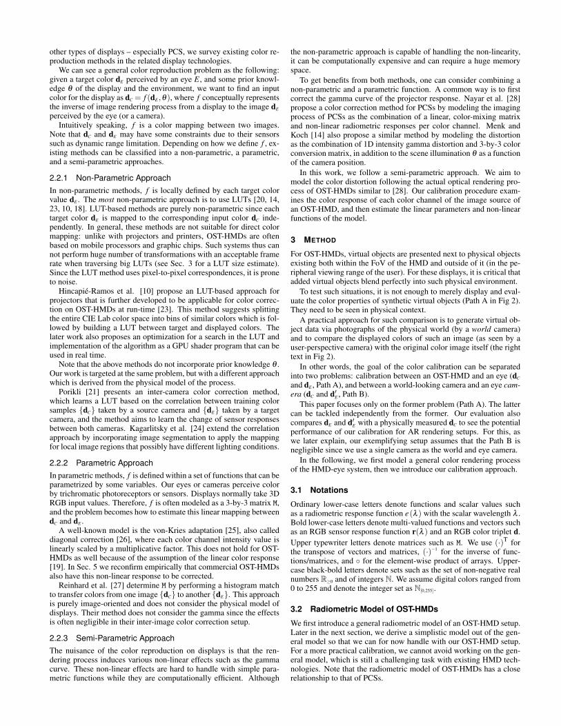
Fig. 3. Channel-wise responses of a Moverio BT-100 OST-HMD wheneach color channel is separately displayed. The x axes correspond tothe intensity of each pure color dC and each y axis is observed colordE
by a camera. Each color channel suffers from non-linear color distor-tions. At x = 0, one can see the black offsets. Note that we exclude thesaturated y values in around x > 220 from our calibration.
is blocked, and then by capturing the displayed color with a camera.The proposed method uses channel-wise response information insteadof checking all possible color combinations. We display 256 colors ofeach channel on the OST-HMD from black to pure colors. We thenobtain three channel-wise look-up tables:
{ KLUT(dK) : N[0,255]→ N[0,255]}K , (13)
for each primary color K ∈ {R,G,B}.Fig. 3 shows an example of the channel-wise response plots from a
Moverio BT-100, a consumer OST-HMD, measured with an industrialcamera. As we can see, the camera sensor has values in all chan-nels even though the OST-HMD displayed only pure colors separatelyin each channel (channel mixture problem). This is due to differentcolor spectra of the sensor and light source of the display. Further-more, color transformations here are not strictly linear and the distor-tion brings unwanted colors into the image (gamma problem). Finally,note the small offset for purely black input signals (non-black displayproblem).
We will now show how each of these three problems can be reduced.
Gamma model: To correct the non-linear color distortion due togamma, we first regress a function on the color response curve ofeach primary color K ∈ {R,G,B}. We use a 2-term power functionK f (dK | Kα, Kβ , Kγ) = Kα + Kβ ∗pow(dK ,
Kγ) for this regression,
{ KLUT(dK)≈ K f (dK) : R≥0→ R≥0}K , (14)
as it provides reasonable approximation without performance hit.Given an input digital color d := [dR,dB,dG]
T, we treat the non-linearbrightness response of the display as
g−1H (d)≈ f (d) = [ R f (dR),
B f (dB),G f (dG)]
T, (15)
where f : R3≥0→R3
≥0 couples the three regressed functions. We obtainraw, linearized color response curves by plotting sets
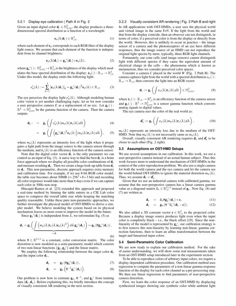
LSK := {( K f (dL),KLUT(dL))} , dL ∈ [0, ...,255], (16)
for all color channel pairs of the primary color K and subcolor L. Fig.4 shows total 9 curves on the BT-100 setting based on each LSK .
Channel Mixture Model with the Black Offset: The resultingcolor plots are subject to linear regression on the next step.
We note the linear regression functions for each LSK asLaK
LdK +LbK = 0. (17)
From Eq. (17), we construct linear correction transformation ex-pressed by a 3-by-3 matrix M−1D−1
E and a 3-vector c:
M−1D−1E ≈
RaRRaG
RaBGaR
GaGGaB
BaRBaG
BaB
︸ ︷︷ ︸
=:A
, c =
RbR +GbR +
BbRRbG +
GbG +BbG
RbB +GbB +
BbB
/3
(18)
x
0 50 100 150 200 250
y
0
50
100
150
200
250
Red
x
0 50 100 150 200 250
y
0
50
100
150
200
250
Green
x
0 50 100 150 200 250
y
0
50
100
150
200
250
Blue
Fig. 4. Linearized channel-wise color responses of the OST-HMD basedon LSK from Eq. (16). In each figure, the x axis is the primary color valueof the input color (e.g., [ R f (dR),0,0]T), and the y axis is the correspond-ing response color (e.g., [ RLUT(dR),0,0]T). In each color channel, thetwo subcolors are also linearized well by the channel-wise gamma cor-rection in addition to the primary colors.
0 50 100 150 200 250
0
50
100
150
200
250
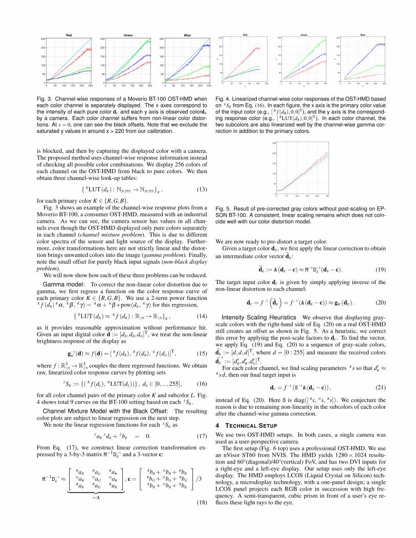
Fig. 5. Result of pre-corrected gray colors without post-scaling on EP-SON BT-100. A consistent, linear scaling remains which does not coin-cide well with our color distortion model.
We are now ready to pre-distort a target color.Given a target color dE , we first apply the linear correction to obtain
an intermediate color vector d̃E :
d̃E := A(dE − c)≈ M−1D−1E (dE − c). (19)
The target input color dC is given by simply applying inverse of thenon-linear distortion to each channel:
dC = f −1(
d̃E
)= f −1 (A(dE − c))≈ gH (dE) . (20)
Intensity Scaling Heuristics We observe that displaying gray-scale colors with the right-hand side of Eq. (20) on a real OST-HMDstill creates an offset as shown in Fig. 5. As a heuristic, we correctthis error by applying the post-scale factors to dC. To find the vector,we apply Eq. (19) and Eq. (20) to a sequence of gray-scale colors,d̂E := [d,d,d]T, where d = [0 : 255] and measure the received colorsd̂E′:= [d′R,d
′B,d′G]
T.For each color channel, we find scaling parameters Ks so that d′K ≈
Ksd, then our final target input is
dC = f −1 (S−1A(dE − c)) , (21)
instead of Eq. (20). Here S is diag([ Rs, Gs, Bs]). We conjecture thereason is due to remaining non-linearity in the subcolors of each colorafter the channel-wise gamma correction.
4 TECHNICAL SETUP
We use two OST-HMD setups. In both cases, a single camera wasused as a user-perspective camera.
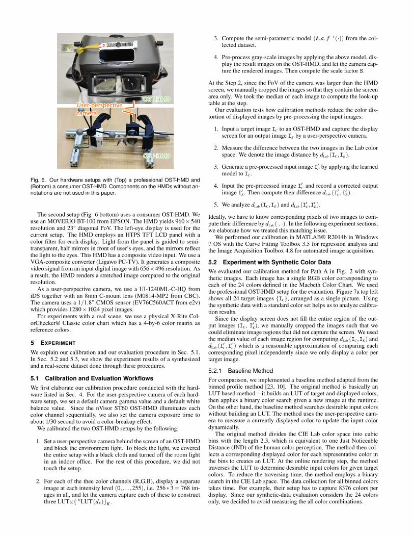
The first setup (Fig. 6 top) uses a professional OST-HMD. We usean nVisor ST60 from NVIS. The HMD yields 1280× 1024 resolu-tion and 60°(diagonal)/40°(vertical) FoV, and has two DVI inputs fora right-eye and a left-eye display. Our setup uses only the left-eyedisplay. The HMD employs LCOS (Liquid Crystal on Silicon) tech-nology, a microdisplay technology, with a one-panel design; a singleLCOS panel projects each RGB color in succession with high fre-quency. A semi-transparent, cubic prism in front of a user’s eye re-flects these light rays to the eye.
User-perspectivecamera
OST-HMD
OST-HMD
Fig. 6. Our hardware setups with (Top) a professional OST-HMD and(Bottom) a consumer OST-HMD. Components on the HMDs without an-notations are not used in this paper.
The second setup (Fig. 6 bottom) uses a consumer OST-HMD. Weuse an MOVERIO BT-100 from EPSON. The HMD yields 960×540resolution and 23° diagonal FoV. The left-eye display is used for thecurrent setup. The HMD employs an HTPS TFT LCD panel with acolor filter for each display. Light from the panel is guided to semi-transparent, half mirrors in front of user’s eyes, and the mirrors reflectthe light to the eyes. This HMD has a composite video input. We use aVGA-composite converter (Ligawo PC-TV). It generates a compositevideo signal from an input digital image with 656×496 resolution. Asa result, the HMD renders a stretched image compared to the originalresolution.
As a user-perspective camera, we use a UI-1240ML-C-HQ fromiDS together with an 8mm C-mount lens (M0814-MP2 from CBC).The camera uses a 1/1.8” CMOS sensor (EV76C560ACT from e2v)which provides 1280×1024 pixel images.
For experiments with a real scene, we use a physical X-Rite Col-orChecker® Classic color chart which has a 4-by-6 color matrix asreference colors.
5 EXPERIMENT
We explain our calibration and our evaluation procedure in Sec. 5.1.In Sec. 5.2 and 5.3, we show the experiment results of a synthesizedand a real-scene dataset done through these procedures.
5.1 Calibration and Evaluation WorkflowsWe first elaborate our calibration procedure conducted with the hard-ware listed in Sec. 4. For the user-perspective camera of each hard-ware setup, we set a default camera gamma value and a default whitebalance value. Since the nVisor ST60 OST-HMD illuminates eachcolor channel sequentially, we also set the camera exposure time toabout 1/30 second to avoid a color-breakup effect.
We calibrated the two OST-HMD setups by the following:
1. Set a user-perspective camera behind the screen of an OST-HMDand block the environment light. To block the light, we coveredthe entire setup with a black cloth and turned off the room lightin an indoor office. For the rest of this procedure, we did nottouch the setup.
2. For each of the thee color channels (R,G,B), display a separateimage at each intensity level (0, . . . ,255), i.e. 256∗3 = 768 im-ages in all, and let the camera capture each of these to constructthree LUTs:{ KLUT(dK)}K .
3. Compute the semi-parametric model (A,c, f −1 (·)) from the col-lected dataset.
4. Pre-process gray-scale images by applying the above model, dis-play the result images on the OST-HMD, and let the camera cap-ture the rendered images. Then compute the scale factor S.
At the Step 2, since the FoV of the camera was larger than the HMDscreen, we manually cropped the images so that they contain the screenarea only. We took the median of each image to compute the look-uptable at the step.
Our evaluation tests how calibration methods reduce the color dis-tortion of displayed images by pre-processing the input images:
1. Input a target image IC to an OST-HMD and capture the displayscreen for an output image IE by a user-perspective camera.
2. Measure the difference between the two images in the Lab colorspace. We denote the image distance by dLab (IC,IE).
3. Generate a pre-processed input image I′C by applying the learnedmodel to IC.
4. Input the pre-processed image I′C and record a corrected outputimage I′E . Then compute their difference dLab (I
′C,I′E).
5. We analyze dLab (IC,IE) and dLab (I′C,I′E).
Ideally, we have to know corresponding pixels of two images to com-pute their difference by dLab (·, ·). In the following experiment sections,we elaborate how we treated this matching issue.
We performed our calibration in MATLAB® R2014b in Windows7 OS with the Curve Fitting Toolbox 3.5 for regression analysis andthe Image Acquisition Toolbox 4.8 for automated image acquisition.
5.2 Experiment with Synthetic Color DataWe evaluated our calibration method for Path A in Fig. 2 with syn-thetic images. Each image has a single RGB color corresponding toeach of the 24 colors defined in the Macbeth Color Chart. We usedthe professional OST-HMD setup for the evaluation. Figure 7a top leftshows all 24 target images {IC}, arranged as a single picture. Usingthe synthetic data with a standard color set helps us to analyze calibra-tion results.
Since the display screen does not fill the entire region of the out-put images (IE , I′E), we manually cropped the images such that wecould eliminate image regions that did not capture the screen. We usedthe median value of each image region for computing dLab (IC,IE) anddLab (I
′C,I′E) which is a reasonable approximation of comparing each
corresponding pixel independently since we only display a color pertarget image.
5.2.1 Baseline MethodFor comparison, we implemented a baseline method adapted from thebinned profile method [23, 10]. The original method is basically anLUT-based method – it builds an LUT of target and displayed colors,then applies a binary color search given a new image at the runtime.On the other hand, the baseline method searches desirable input colorswithout building an LUT. The method uses the user-perspective cam-era to measure a currently displayed color to update the input colordynamically.
The original method divides the CIE Lab color space into cubicbins with the length 2.3, which is equivalent to one Just NoticeableDistance (JND) of the human color perception. The method then col-lects a corresponding displayed color for each representative color inthe bins to creates an LUT. At the online rendering step, the methodtraverses the LUT to determine desirable input colors for given targetcolors. To reduce the traversing time, the method employs a binarysearch in the CIE Lab space. The data collection for all binned colorstakes time. For example, their setup has to capture 8376 colors perdisplay. Since our synthetic-data evaluation considers the 24 colorsonly, we decided to avoid measuring the all color combinations.
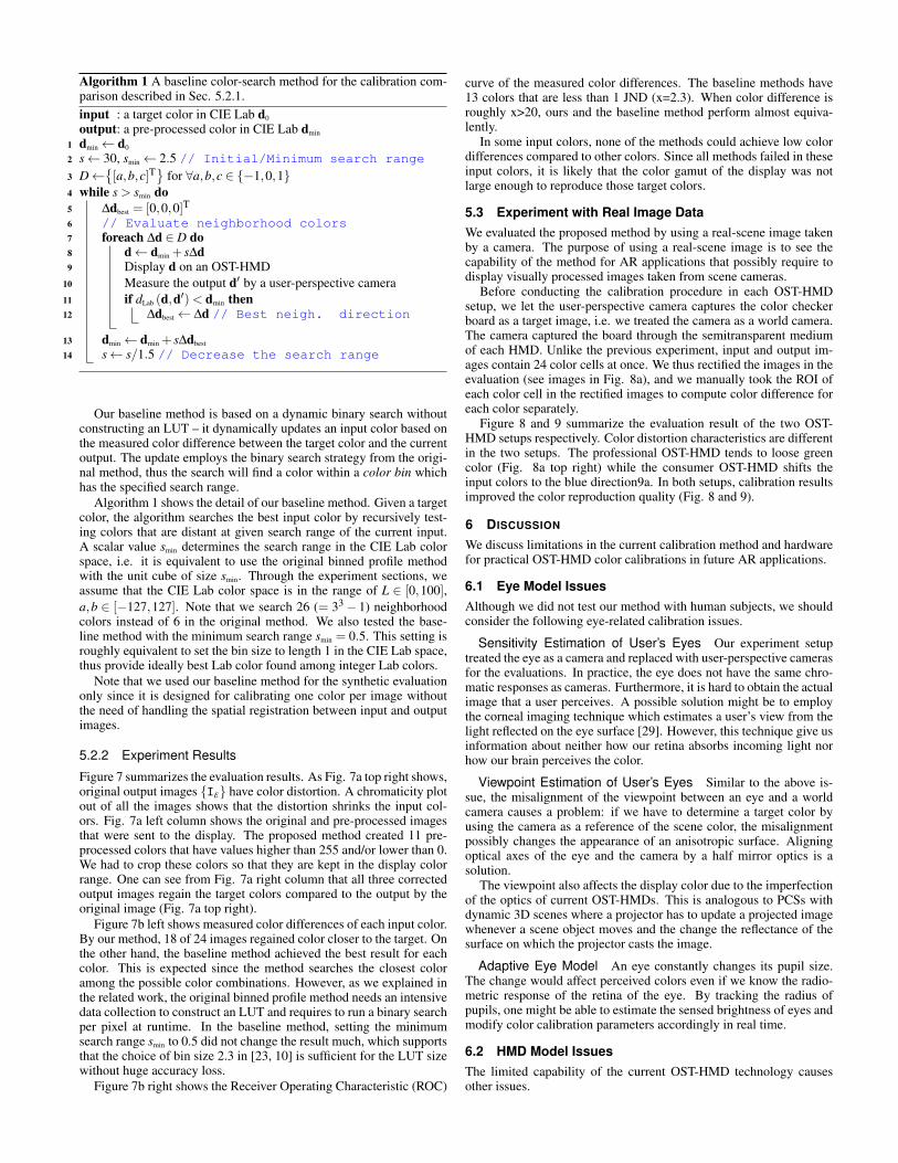
Algorithm 1 A baseline color-search method for the calibration com-parison described in Sec. 5.2.1.input : a target color in CIE Lab d0
output: a pre-processed color in CIE Lab dmin
1 dmin← d0
2 s← 30, smin← 2.5 // Initial/Minimum search range
3 D←{[a,b,c]T
}for ∀a,b,c ∈ {−1,0,1}
4 while s > smin do5 ∆dbest = [0,0,0]T6 // Evaluate neighborhood colors7 foreach ∆d ∈ D do8 d← dmin + s∆d9 Display d on an OST-HMD
10 Measure the output d′ by a user-perspective camera11 if dLab (d,d′)< dmin then12 ∆dbest← ∆d // Best neigh. direction
13 dmin← dmin + s∆dbest
14 s← s/1.5 // Decrease the search range
Our baseline method is based on a dynamic binary search withoutconstructing an LUT – it dynamically updates an input color based onthe measured color difference between the target color and the currentoutput. The update employs the binary search strategy from the origi-nal method, thus the search will find a color within a color bin whichhas the specified search range.
Algorithm 1 shows the detail of our baseline method. Given a targetcolor, the algorithm searches the best input color by recursively test-ing colors that are distant at given search range of the current input.A scalar value smin determines the search range in the CIE Lab colorspace, i.e. it is equivalent to use the original binned profile methodwith the unit cube of size smin. Through the experiment sections, weassume that the CIE Lab color space is in the range of L ∈ [0,100],a,b ∈ [−127,127]. Note that we search 26 (= 33− 1) neighborhoodcolors instead of 6 in the original method. We also tested the base-line method with the minimum search range smin = 0.5. This setting isroughly equivalent to set the bin size to length 1 in the CIE Lab space,thus provide ideally best Lab color found among integer Lab colors.
Note that we used our baseline method for the synthetic evaluationonly since it is designed for calibrating one color per image withoutthe need of handling the spatial registration between input and outputimages.
5.2.2 Experiment Results
Figure 7 summarizes the evaluation results. As Fig. 7a top right shows,original output images {IE} have color distortion. A chromaticity plotout of all the images shows that the distortion shrinks the input col-ors. Fig. 7a left column shows the original and pre-processed imagesthat were sent to the display. The proposed method created 11 pre-processed colors that have values higher than 255 and/or lower than 0.We had to crop these colors so that they are kept in the display colorrange. One can see from Fig. 7a right column that all three correctedoutput images regain the target colors compared to the output by theoriginal image (Fig. 7a top right).
Figure 7b left shows measured color differences of each input color.By our method, 18 of 24 images regained color closer to the target. Onthe other hand, the baseline method achieved the best result for eachcolor. This is expected since the method searches the closest coloramong the possible color combinations. However, as we explained inthe related work, the original binned profile method needs an intensivedata collection to construct an LUT and requires to run a binary searchper pixel at runtime. In the baseline method, setting the minimumsearch range smin to 0.5 did not change the result much, which supportsthat the choice of bin size 2.3 in [23, 10] is sufficient for the LUT sizewithout huge accuracy loss.
Figure 7b right shows the Receiver Operating Characteristic (ROC)
curve of the measured color differences. The baseline methods have13 colors that are less than 1 JND (x=2.3). When color difference isroughly x>20, ours and the baseline method perform almost equiva-lently.
In some input colors, none of the methods could achieve low colordifferences compared to other colors. Since all methods failed in theseinput colors, it is likely that the color gamut of the display was notlarge enough to reproduce those target colors.
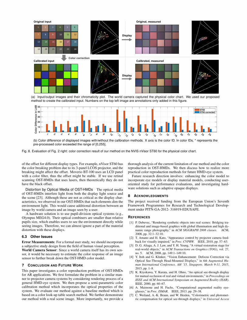
5.3 Experiment with Real Image DataWe evaluated the proposed method by using a real-scene image takenby a camera. The purpose of using a real-scene image is to see thecapability of the method for AR applications that possibly require todisplay visually processed images taken from scene cameras.
Before conducting the calibration procedure in each OST-HMDsetup, we let the user-perspective camera captures the color checkerboard as a target image, i.e. we treated the camera as a world camera.The camera captured the board through the semitransparent mediumof each HMD. Unlike the previous experiment, input and output im-ages contain 24 color cells at once. We thus rectified the images in theevaluation (see images in Fig. 8a), and we manually took the ROI ofeach color cell in the rectified images to compute color difference foreach color separately.
Figure 8 and 9 summarize the evaluation result of the two OST-HMD setups respectively. Color distortion characteristics are differentin the two setups. The professional OST-HMD tends to loose greencolor (Fig. 8a top right) while the consumer OST-HMD shifts theinput colors to the blue direction9a. In both setups, calibration resultsimproved the color reproduction quality (Fig. 8 and 9).
6 DISCUSSION
We discuss limitations in the current calibration method and hardwarefor practical OST-HMD color calibrations in future AR applications.
6.1 Eye Model IssuesAlthough we did not test our method with human subjects, we shouldconsider the following eye-related calibration issues.
Sensitivity Estimation of User’s Eyes Our experiment setuptreated the eye as a camera and replaced with user-perspective camerasfor the evaluations. In practice, the eye does not have the same chro-matic responses as cameras. Furthermore, it is hard to obtain the actualimage that a user perceives. A possible solution might be to employthe corneal imaging technique which estimates a user’s view from thelight reflected on the eye surface [29]. However, this technique give usinformation about neither how our retina absorbs incoming light norhow our brain perceives the color.
Viewpoint Estimation of User’s Eyes Similar to the above is-sue, the misalignment of the viewpoint between an eye and a worldcamera causes a problem: if we have to determine a target color byusing the camera as a reference of the scene color, the misalignmentpossibly changes the appearance of an anisotropic surface. Aligningoptical axes of the eye and the camera by a half mirror optics is asolution.
The viewpoint also affects the display color due to the imperfectionof the optics of current OST-HMDs. This is analogous to PCSs withdynamic 3D scenes where a projector has to update a projected imagewhenever a scene object moves and the change the reflectance of thesurface on which the projector casts the image.
Adaptive Eye Model An eye constantly changes its pupil size.The change would affect perceived colors even if we know the radio-metric response of the retina of the eye. By tracking the radius ofpupils, one might be able to estimate the sensed brightness of eyes andmodify color calibration parameters accordingly in real time.
6.2 HMD Model IssuesThe limited capability of the current OST-HMD technology causesother issues.

Lab search with s = 2.3
Proposed
Original
Lab search with s = 0.5
Display
Display
Display
Display
Color correction
1 2 3 4 5 6
7 8 9 10 11 12
13 14 15 16 17 18
19 20 21 22 23 24
Color IDs are only for this visualization
(a) Images captured by the user-perspective camera and their chromaticity diagrams. We tiled 24 color images in one picture forvisualization purpose in the input/output images shown above. The chromaticity diagram on the left column also have bigger colorpoints for the same purpose. Numbers on the top left image are annotations added only for this figure.
Color ID
1 2 3 * 4 5 6 * 7 8 9 * 10* 11
* 12* 13
* 14* 15
* 16* 17
* 1819 20 21 22 23 24
Co
lor
Dif
fere
nce in
LA
B
0
20
40
60Original
Proposed
Lab Search (s=2.3)
Lab Search (s=0.5)
Color Diff. in Lab
0 20 40 60
Co
lor
Co
un
t
0
5
10
15
20
25
Original
Proposed
Lab Search (s=2.3)
Lab Search (s=0.5)
1 JND (X=2.3)
(b) (Left) Color difference of displayed images with/without the calibration methods. In color IDs, * represents the pre-processed colorexceeded the range of [0,255]. Lab Search (s=X) are our baseline methods with the minimum search range X. Even with those ideal colorsearch results, some color IDs have large errors. This implies that the color range of the OST-HMD was not enough to reproduce certaincolors. (Right) An ROC curve of the left plot. The y axis shows the number of colors that have errors smaller than x-axis values.
Fig. 7. Evaluation of Path A in Fig. 2: Color correction results of the NVIS nVisor ST60 with the synthetic, digital color set.
Display Color Range If the color range of an OST-HMD is ex-tremely smaller than target colors, there is no hope for good color cal-ibration. As we explained in the experiment section, a pre-processedcolor can be those out of the color range of a display. For example,when a pre-processed color contains negative values, we have to trun-cate the values to zero or at least to positive. Thus the displayed colorwould appear brighter than the target color. A workaround is to addan opaque layer to OST-HMDs to reduce the amount of light coming
into eye [5, 6]. Especially, [6] has a capability to control opaquenessby modulating its opaque LCD layers. Another solution is to find acloser target color which can be represented by a given color range ofthe display.
Display Color Characteristics As we saw in the experiment,most OST-HMDs have the black offsets. Since different optics havedifferent illumination characteristics [30], we would need a modeling
Original input
Calibrated input
Original, measured
Calibrated, measured
1 2 3 4 5 6
7 8 9 10 11 12
13 14 15 16 17 18
19 20 21 22 23 24
Display
Display
Color correction
(a) Input/output images and their chromaticity plot. The world camera captured the physical color chart. We used our proposedmethod to create the calibrated input. Numbers on the top left image are annotations only added in this figure.
Color ID
1 2 3 4 5 * 6* 7
8 9 10 * 11* 12
13 14 15 * 1617 18 * 19
20 21 22 23 24
Co
lor D
iffe
ren
ce in
LA
B
0
10
20
30
40
50
ST60
ST60 corrected
(b) Color difference of displayed images with/without the calibration methods. X axis is the color ID. In color IDs, * represents thepre-processed color exceeded the range of [0,255].
Fig. 8. Evaluation of Fig. 2 right: color correction result of our method on the NVIS nVisor ST60 for the physical color chart.
of the offset for different display types. For example, nVisor ST60 hasthe color breaking problem due to its 3-panel LCOS projector, and thebreaking might affect the offset. Moverio BT-100 uses an LCD panelwith a color filter, thus the offset might be stable. If we use retinalscanning OST-HMDs that uses lasers, then theoretically they do nothave the black offset.
Distortion by Optical Media of OST-HMDs The optical mediaof OST-HMDs interfere light from both the display light source andthe scene [23]. Although these are not as critical as the display char-acteristics, we observed in our OST-HMDs that such elements dim theenvironment light. This would cause additional distortion between animage by world camera and an image seen by a user.
A hardware solution is to use pupil-division optical systems (e.g.,Olympus MEG4.0). Their optical combiners are smaller than relativepupils size, which enables users to see the environment directly whileseeing images. Therefore, we can almost ignore a part of the materialdistortion with these displays.
6.3 Other IssuesError Measurements: For a formal user study, we should incorporatea subjective study design from the field of human visual perception.World Camera Sensor: Since a world camera itself has its own sen-sor, it would be necessary to estimate the color response of an imagesensor to further break down the OST-HMD color model.
7 CONCLUSION AND FUTURE WORK
This paper investigates a color reproduction problem of OST-HMDsfor AR applications. We first formulate the problem in a similar man-ner to projector camera systems by considering rendering process of ageneral HMD-eye system. We then propose a semi-parametric colorcalibration method which incorporates the optical properties of thesystem. We evaluate our method against a baseline method which isbased on a color look-up table search method. We further demonstrateour method with a real scene image. More importantly, we provide a
thorough analysis of the current limitation of our method and the colorreproduction in OST-HMDs. We then discuss how to realize morepractical color reproduction methods for future HMD-eye system.
Future research direction involves: enhancing the color model toincorporate eye models or display material models, conducting user-oriented study for performance evaluations, and investigating hard-ware solutions such as adaptive opaque displays.
8 ACKNOWLEDGMENTS
The project received funding from the European Union’s SeventhFramework Programmes for Research and Technological Develop-ment under PITN-GA-2012- 316919-EDUSAFE.
REFERENCES
[1] P. Debevec, “Rendering synthetic objects into real scenes: Bridging tra-ditional and image-based graphics with global illumination and high dy-namic range photography,” in ACM SIGGRAPH 2008 classes. ACM,2008, pp. 32:1–32:10.
[2] T. Amano and H. Kato, “Appearance control by projector camera feed-back for visually impaired,” in Proc. CVPRW. IEEE, 2010, pp. 57–63.
[3] D. G. Aliaga, A. J. Law, and Y. H. Yeung, “A virtual restoration stage forreal-world objects,” in ACM Transactions on Graphics (TOG), vol. 27,no. 5. ACM, 2008, pp. 149:1–149:10.
[4] Y. Itoh and G. Klinker, “Vision Enhancement: Defocus Correction viaOptical See-Through Head-Mounted Displays,” in 6th Augmented Hu-man International Conference, AH ’15, Singapore, March 9-11, 2015,2015, pp. 1–8.
[5] K. Kiyokawa, Y. Kurata, and H. Ohno, “An optical see-through displayfor mutual occlusion of real and virtual environments,” in Proceedings onIEEE and ACM International Symposium on Augmented Reality (ISAR).IEEE, 2000, pp. 60–67.
[6] A. Maimone and H. Fuchs, “Computational augmented reality eye-glasses,” in Proc. ISMAR. IEEE, 2013, pp. 29–38.
[7] C. Weiland, A.-K. Braun, and W. Heiden, “Colorimetric and photomet-ric compensation for optical see-through displays,” in Universal Access

Original input
Calibrated input
Original, measured
Calibrated, measured
1 2 3 4 5 6
7 8 9 10 11 12
13 14 15 16 17 18
19 20 21 22 23 24
Display
Display
4, 7, 11, 12, 14, 15, 16
Color correction
(a) Input/output images and their chromaticity plot. The world camera captured the physical color chart. We used our proposedmethod to create the calibrated input. Numbers on the top left image are annotations only added in this figure.
Color ID
1 2 3 * 45 6 * 7
8 9 10 * 11* 12
13 * 14* 15
* 1617 18 19 20 21 22 23 24
Co
lor D
iffe
ren
ce in
LA
B
0
10
20
30
40
50
BT100
BT100 corrected
(b) Color difference of displayed images with/without the calibration methods. X axis is the color ID. In color IDs, * represents thepre-processed color exceeded the range of [0,255].
Fig. 9. Evaluation of Fig. 2 right: color correction result of our method on the EPSON Moverio BT100 for the physical color chart.
in Human-Computer Interaction. Intelligent and Ubiquitous InteractionEnvironments. Springer, 2009, pp. 603–612.
[8] O. Cakmakci and J. Rolland, “Head-worn displays: a review,” Journal ofDisplay Technology, vol. 2, no. 3, pp. 199–216, 2006.
[9] J. P. Rolland and H. Fuchs, “Optical versus video see-through head-mounted displays in medical visualization,” Presence: Teleoperators andVirtual Environments, vol. 9, no. 3, pp. 287–309, 2000.
[10] S. K. Sridharan, J. D. Hincapié-Ramos, D. R. Flatla, and P. Irani, “Colorcorrection for optical see-through displays using display color profiles,”in Proceedings of the 19th ACM Symposium on Virtual Reality Softwareand Technology. ACM, 2013, pp. 231–240.
[11] W. Lee and W. Woo, “Real-time color correction for marker-based aug-mented reality applications,” in International Workshop on UbiquitousVirtual Reality, 2009, pp. 32–25.
[12] S. B. Knorr and D. Kurz, “Real-time illumination estimation from facesfor coherent rendering,” in Proc. ISMAR. IEEE, 2014, pp. 113–122.
[13] J. Fischer, D. Bartz, and W. Straßer, “Enhanced visual realism by incorpo-rating camera image effects,” in Proc. ISMAR. IEEE Computer Society,2006, pp. 205–208.
[14] C. Menk and R. Koch, “Truthful color reproduction in spatial augmentedreality applications,” Visualization and Computer Graphics, IEEE Trans-actions on, vol. 19, no. 2, pp. 236–248, 2013.
[15] M. Brown, A. Majumder, and R. Yang, “Camera-based calibration tech-niques for seamless multiprojector displays,” Visualization and ComputerGraphics, IEEE Transactions on, vol. 11, no. 2, pp. 193–206, 2005.
[16] A. Ilie and G. Welch, “Ensuring color consistency across multiple cam-eras,” in Proc. ICCV, vol. 2. IEEE, 2005, pp. 1268–1275.
[17] A. Madi and D. Ziou, “Color constancy for visual compensation of pro-jector displayed image,” Displays, vol. 35, no. 1, pp. 6–17, 2014.
[18] A. Majumder, Z. He, H. Towles, and G. Welch, “Achieving color unifor-mity across multi-projector displays,” in Visualization 2000. Proceedings.IEEE, 2000, pp. 117–124.
[19] A. Majumder, “Properties of color variation across multi-projector dis-plays,” Proceedings of SID Eurodisplay, vol. 2002, pp. 1–4, 2002.
[20] R. D. Myers, “Method and system for color matching between digitaldisplay devices,” Jun. 6 2000, US Patent 6,072,902.
[21] F. Porikli, “Inter-camera color calibration by correlation model function,”in Proceedings on International Conference on Image Processing (ICIP),vol. 2. IEEE, 2003, pp. 133–136.
[22] M. D. Grossberg, H. Peri, S. K. Nayar, and P. N. Belhumeur, “Makingone object look like another: Controlling appearance using a projector-camera system,” vol. 1. IEEE Computer Society, 2004, pp. 452–459.
[23] J. David Hincapié-Ramos, L. Ivanchuk, S. K. Sridharan, and P. Irani,“Smartcolor: Real-time color correction and contrast for optical see-through head-mounted displays,” in Proc. ISMAR. IEEE, 2014, pp.187–194.
[24] S. Kagarlitsky, Y. Moses, and Y. Hel-Or, “Piecewise-consistent colormappings of images acquired under various conditions,” in Proc. ICCV.IEEE, 2009, pp. 2311–2318.
[25] D. Jameson and L. M. Hurvich, “Theory of brightness and color contrastin human vision,” Vision Research, vol. 4, no. 1, pp. 135–154, 1964.
[26] A. Gijsenij, T. Gevers, and J. Van De Weijer, “Computational color con-stancy: Survey and experiments,” Image Processing, IEEE Transactionson, vol. 20, no. 9, pp. 2475–2489, 2011.
[27] E. Reinhard, M. Ashikhmin, B. Gooch, and P. Shirley, “Color transferbetween images,” IEEE Computer graphics and applications, vol. 21,no. 5, pp. 34–41, 2001.
[28] S. K. Nayar, H. Peri, M. D. Grossberg, and P. N. Belhumeur, “A projec-tion system with radiometric compensation for screen imperfections,” inICCV workshop on projector-camera systems (PROCAMS), vol. 3. Cite-seer, 2003.
[29] C. Nitschke, A. Nakazawa, and H. Takemura, “Corneal Imaging Revis-ited: An Overview of Corneal Reflection Analysis and Applications,”IPSJ Trans. Computer Vision and Applications, vol. 5, pp. 1–18, 2013.
[30] P. Bodrogi and T. Q. Khanh, “Colorimetric and color appearance-basedcharacterization of displays,” Illumination, Color and Imaging: Evalua-tion and Optimization of Visual Displays, pp. 25–95, 2012.