semianalytical geometry-property relationships for some
TRANSCRIPT

Delft University of Technology
Semianalytical geometry-property relationships for some generalized classes ofpentamodelike additively manufactured mechanical metamaterials
Hedayati, R.; Jedari Salami, S.; Li, Yageng; Sadighi, M.; Zadpoor, A. A.
DOI10.1103/PhysRevApplied.11.034057Publication date2019Document VersionFinal published versionPublished inPhysical Review Applied
Citation (APA)Hedayati, R., Jedari Salami, S., Li, Y., Sadighi, M., & Zadpoor, A. A. (2019). Semianalytical geometry-property relationships for some generalized classes of pentamodelike additively manufactured mechanicalmetamaterials. Physical Review Applied, 11(3), [034057].https://doi.org/10.1103/PhysRevApplied.11.034057Important noteTo cite this publication, please use the final published version (if applicable).Please check the document version above.
CopyrightOther than for strictly personal use, it is not permitted to download, forward or distribute the text or part of it, without the consentof the author(s) and/or copyright holder(s), unless the work is under an open content license such as Creative Commons.
Takedown policyPlease contact us and provide details if you believe this document breaches copyrights.We will remove access to the work immediately and investigate your claim.
This work is downloaded from Delft University of Technology.For technical reasons the number of authors shown on this cover page is limited to a maximum of 10.

PHYSICAL REVIEW APPLIED 11, 034057 (2019)
Semianalytical Geometry-Property Relationships for Some Generalized Classes ofPentamodelike Additively Manufactured Mechanical Metamaterials
R. Hedayati,1,* S. Jedari Salami,2 Y. Li,1 M. Sadighi,3 and A.A. Zadpoor4
1Novel Aerospace Materials group, Faculty of Aerospace Engineering, Delft University of Technology (TU Delft),Kluyverweg 1, 2629 HS, Delft, The Netherlands
2Department of Mechanical Engineering, Damavand branch, Islamic Azad University, Damavand, Iran3Department of Mechanical Engineering, Amirkabir University of Technology (Tehran Polytechnic), Hafez Ave,
Tehran, Iran4Department of Biomechanical Engineering, Faculty of Mechanical, Maritime, and Materials Engineering, Delft
University of Technology (TU Delft), Mekelweg 2, 2628 CD, Delft, The Netherlands
(Received 20 July 2018; revised manuscript received 9 January 2019; published 22 March 2019)
We study a special class of mechanical metamaterials, namely lattices, based on beams (struts) withnonuniform cross sections, of which pentamode mechanical metamaterials are a special case. Fivesymmetric beam types including simple cylinder, concave double cone, convex double cone, concavehyperbolic, and convex hyperbolic are considered. Three types of loads including lateral force, axial force,and moment are applied to the free end of cantilever beams with the five aforementioned geometries andtheir responses are compared in terms of displacement, normal stress variation along the beam length, andshear stress variation along the beam length. Using the displacement diagrams obtained for different strutgeometries and loading conditions, semi-analytical relationships are derived for the displacement at theend of cantilever beams. The semi-analytical relationships are then used to calculate the elastic modulusand yield strength of lattice structures based on two types of unit cells, namely diamond and cube. Wealso build numerical models and perform experiments to benchmark our semi-analytical results. Compar-ison of the analytical, numerical, and experimental results demonstrate the accuracy of the semi-analyticalrelationships presented for the mechanical properties of this class of mechanical metamaterials. Moreover,in both the cube- and diamond-based structures, increasing the α value (i.e., the ratio of the largest to thesmallest cross-section radius in each strut) at a constant relative density decreases the elastic modulus,yield strength, the initial maximum stress, and the plateau stress.
DOI: 10.1103/PhysRevApplied.11.034057
I. INTRODUCTION
Metamaterials are engineered structures that are ratio-nally designed to exhibit unusual physical properties. Theyare often called after the type of the physical property theytarget, for example, optical metamaterials [1,2], acousticmetamaterials [3,4], or mechanical metamaterials [5–8].Mechanical metamaterials, in particular, aim at achiev-ing unusual mechanical properties not readily found innature such as negative Poisson’s ratio [9–12], nega-tive compressibility [13,14], ultrahigh stiffness [15], ornegative elasticity [16,17]. The small-scale geometry ofmechanical metamaterials determines the properties theyexhibit at larger scales. Geometry-property relationshipsare, therefore, of utmost interest in the process of rationallydesigning mechanical metamaterials.
Geometries that are based upon beam-like ele-ments (sometimes called struts) have been often usedfor development of mechanical metamaterials. In this
*[email protected]; [email protected]
approach, a number of struts are used to create a space-filling unit cell that is then repeated in different directionsto create the microarchitecture of the metamaterial. Oneadvantage of the geometries based on beam-like elementsis that beam theories such as Euler-Bernoulli or Timo-shenko can be used to derive analytical geometry-propertyrelationships [18–20].
A natural extension of the geometries based on beamswith constant cross sections is to allow for beams withvariable cross sections. Milton and Cherkaev have shownin their seminal paper [21] that lattices based on beamswith variable cross sections could be the basis for creatingpentamode metamaterials. Pentamode metamaterials are aspecial class of extremal materials that exhibit unusuallyhigh resistance against deformations in certain directions(associated with the extremely large eigenvalues of theelasticity tensor), while being extremely compliant in someother directions (associated with the near-zero eigenval-ues of the elasticity tensor). In the case of pentamodemetamaterials, the extremely large and near-zero eigen-values of the elasticity tensor translate to a very large
2331-7019/19/11(3)/034057(20) 034057-1 © 2019 American Physical Society

R. HEDAYATI et al. PHYS. REV. APPLIED 11, 034057 (2019)
bulk modulus and negligible shear modulus. That is whypentamode metamaterials are sometimes called metafluids[22,23]. More importantly, Milton and Cherkaev haveshown that pentamode metamaterials can be used as aplatform for realizing metamaterials with any thermo-dynamically admissible elasticity tensor [21]. Pentamodemetamaterials were not manufactured until 2012 [24] whenthe availability of advanced additive manufacturing [three-dimensional (3D) printing] techniques allowed for theirrealization. Continued improvement of additive manufac-turing techniques that allow for fabrication of metamate-rials with arbitrarily complex geometries on one hand andthe potential of pentamode-like metamaterials as a generalplatform for the design of mechanical metamaterials withany given elasticity tensor on the other hand highlight theimportance of deriving analytical geometry-property rela-tionships for lattices based on beams with variable crosssections.
An important barrier to deriving such relationships isthat theories comparable with Euler-Bernoulli and Timo-shenko do not exist for beams with variable cross sections.In this study, we take an analytical approach to derivean exact beam theory for certain classes of beams withvariable cross sections. The considered types of variablecross sections include not only the type used in pentamodemetamaterials (i.e., convex double cone) but also threeother types (i.e., concave double cone, concave hyper-bolic, and convex hyperbolic). In the next step, we usethe presented beam theory to derive semi-analytical rela-tionships for the mechanical properties of lattices basedon the diamond and cubic unit cells. The geometry pro-posed by Milton and Cherkaev [21] for pentamode meta-materials (i.e., diamond-type lattices made from convexdouble-cone beams) are, thus, a special case of the lat-tices for which we provide semi-analytical relationships.We then compare the mechanical properties predicted byour semi-analytical relationships with the computationalresults obtained using finite element (FE) models. Finally,we use an additive manufacturing (3D printing) techniqueto fabricate specimens with the same type of lattice struc-tures and two types of variable cross sections (convexdouble cone and concave double cone) as used in deriva-tion of the semi-analytical relationships. The predictions ofthe semi-analytical relationships are then compared withthe compressive mechanical properties observed for theadditively manufactured specimens.
II. MATERIALS AND METHODS
A. Analytical and semi-analytical solutions
1. The geometrical relationships
In order to objectively compare the responses of thefive different types of beams, they must have something incommon. Since adjusting the elastic properties of mechan-ical metamaterials given their available mass is important
TABLE I. Formulas for cross-section radius z in differentgeometries.
Left part Right part
Cylinder z = rConcave double cone z = 2(r−R)
l x + R z = 2(R−r)l x + (2r − R)
Convex double cone z = 2(R−r)l x + r z = 2(r−R)
l x + (2R − r)
Concave hyperbolic z = r + D −(
D2 − (x − l
2
)2)1/2
where D = (R−r)2+(
l2
)2
2(R−r)
Convex hyperbolic z = D − R −(
D2 − (x − l
2
)2)1/2
where D = (R−r)2+(
l2
)2
2(R−r)
in a large number of applications, we compare the responseof the different types of beams while fixing their total mass.In all geometries, the ratio of the small radius to the beamlength is denoted by β (i.e., β = r/l), while the ratio ofthe large radius to the small radius is denoted by α, thatis, α = R/r. Table I lists the cross-section radius, z, as afunction of the distance from the strut edge, x, for the dif-ferent geometries considered here. In conical geometries[Figs. 1(d) and 1(e)], the ratio β can be expressed as a func-tion of geometrical dimensions and the volume occupiedby the beam Vstrut as
β =(
3Vstrut
π l3(1 + α + α2)
)1/2
. (1)
In hyperbolic geometries, however, it is not possible toobtain a closed-form equation for β (which subsequentlygives the smaller radius, r). The value of β must, there-fore, be found using numerical methods such as Newton-Raphson. To do this, first a r0 is guessed and the mass ofthe beam is calculated using
M0 = ρ
∫ l
0πz2
0dx, (2)
where z0 = r0 + D0 − {D20 − [x − (l/2)]2}1/2 (according
to Table I) and D0 = {[(α − 1)2r20 + (l/2)2]/[2r0(α − 1)]}.
If the value of M0 − M is nonzero (where M is the givenmass of the strut), a second guess is used for the smallerradius, r
r1 = r0 − f (r0)
f ′(r0), (3)
where f is a function defined as f (ri) = Mi − M with
Mi = ρ
∫ l
0πz2
i dx, (4)
where zi = ri + Di − {D2i − [x − (l/2)]2}1/2 (according to
Table I) and Di = {[(α − 1)2r2i + (l/2)2]/[2ri(α − 1)]}.
034057-2

SEMIANALYTICAL GEOMETRY-PROPERTY. . . PHYS. REV. APPLIED 11, 034057 (2019)
(a) (b)
(c) (d)
(e)
FIG. 1. Five beam geometries considered for analytical study: (a) simple cylinder, (b) concave hyperbolic, (c) convex hyperbolic,(d) concave double-cone, and (e) convex double-cone.
The process is repeated as
rn+1 = rn − f (rn)
f ′(rn), (5)
until a sufficiently accurate value is reached. For each α, aNewton-Raphson loop is used to find r, and thus, R = αr.
2. Beams with variable cross sections
In the Timoshenko beam theory, the displacements ofthe different points of the beam in the x, y, and z directionsare as follows:
u(x, y, z) = zϕ(x) + u0(x),
v(x, y, z) = 0,
w(x, y, z) = w(x), (6)
where (x, y, z) represents the coordinates of a point in thebeam (Fig. 1), ϕ is the angle of the rotation of the normalto the midsurface of the beam, u0 is the displacement of themidsurface in the x direction, and w is the displacement ofthe midsurface in the z direction. The components of thestrain tensor for a beam with linear strains are
εxx = ∂u∂x
= z∂ϕ
∂x+ ∂u0
∂x,
εzx = ∂u∂z
+ ∂w∂x
= ϕ + ∂w∂x
,
εyy = εzz = γxy = γyz = 0. (7)
The corresponding stresses of the beam are, thus, given as
σxx = Esεxx = Es
(∂u0
∂x+ z
∂ϕ
∂x
),
034057-3

R. HEDAYATI et al. PHYS. REV. APPLIED 11, 034057 (2019)
τzx = κGsεzx = κGs
(ϕ + ∂w
∂x
),
σyy = σzz = τxy = τyz = 0, (8)
where Es and Gs are the elastic and shear moduli of thematerial and κ is the Timoshenko’s shear coefficient. Weuse the Ritz method to derive the governing equations ofequilibrium from the total potential energy function of thebeam. The total potential energy ( ) includes the strainenergy (U) and the potential of external forces (W).
= U + W. (9)
The strain energy of the sandwich beam that consists ofenergetically conjugate pairs of stress and strain is givenby
U =∫∫∫ [∫
σxxdεxx +∫
σyydεyy +∫
σzzdεzz
+∫
τxydγxy +∫
τyzdγyz +∫
τxzdγxz
]dV. (10)
The strain energy expression may be obtained by substi-tuting Eq. (8) into Eq. (10) and then integrating over thestrain terms. The resulting relationship is as follows:
U = 12
∫∫∫ [Es
(∂u0
∂x+ z
∂ϕ
∂x
)2
+ κGs
(ϕ + ∂w
∂x
)2]
dV,
= 12
∫ l
x=0
[EsA
(∂u0
∂x
)2
+ EsI(
∂ϕ
∂x
)2
+κGsA(
−ϕ + ∂w∂x
)2]
dx. (11)
The potential energy of external work is equal to
W = −∫ l
x=0[Px u0 + Fz w + Mxy ϕ]δd(x − xk) dx, (12)
where Px, Fz, and Mxy are the external axial and lateralconcentrated loads and the concentrated bending momentsapplied to the beam at point x = xk, respectively. InEq. (12), δd(x − xk) is the Dirac delta function at the loca-tion of the concentrated loads. The three variables w, ϕ,and u0, could be written as the following summations
w =∞∑
i=1
WiSwi ,
ϕ =∞∑
i=1
�iSϕi ,
u0 =∞∑
i=1
UiSui , (13)
where Swi , Sϕ
i , Sui are, respectively, the lateral displacement,
rotational, and axial shape functions that should satisfy theboundary conditions of the beam. Since the beams are can-tilever, a good approximation for all the shape functionsis
Swi = Sϕ
i = Sui =
(xl
)i. (14)
By substituting the shape functions into Eq. (13) and theobtained relationships into Eqs. (11) and (12), the totalpotential energy can be calculated as a function of theunknown displacement coefficients Wi, �i, and Ui as
= 12
∫ l
x=0
[EsA
(∑Ui
∂Sui
∂x
)2
+ EsI(∑
�i∂Sϕ
i
∂x
)2
+κGsA(∑
Wi∂Sw
i
∂x−∑
�iSϕi
)2]
dx
−∫ l
x=0
[Px
∞∑i=1
UiSui + Fz
∞∑i=1
WiSwi
+Mxy
∞∑i=1
�iSϕi
]δd(x − xk) dx. (15)
In this study, only three concentrated loads Px = P, Fz =F , and Mxy = M at x = l are considered. Finally, by insert-ing Eq. (9) into the generalized Lagrange equations, thegoverning equations of the problem are obtained as
∂
∂Wi= 0 →
∫ l
x=0κGsA
∞∑k=1
(Wk
∂Swk
∂x− �kSϕ
k
)∂Sw
i
∂xdx
−∫ l
x=0
∞∑i=1
FSwi δd(x − xk) dx = 0,
∂
∂�i= 0 →
∫ l
x=0EsI
∞∑k=1
(�k
∂Sϕ
k
∂x
)∂Sϕ
i
∂xdx
−∫ l
x=0κGsA
∞∑k=1
(Wk
∂Swk
∂x− �kSϕ
k
)Sϕ
i dx
−∫ l
x=0
∞∑i=1
MSϕi δd(x − xk)dx = 0,
∂
∂Ui= 0 →
∫ l
x=0EsA
∞∑k=1
(Uk
∂SUk
∂x
)∂SU
i
∂xdx
−∫ l
x=0
∞∑i=1
PSUi δd(x − xk)dx = 0. (16)
Therefore,
034057-4
SEMIANALYTICAL GEOMETRY-PROPERTY. . . PHYS. REV. APPLIED 11, 034057 (2019)
⎡⎢⎢⎢⎢⎢⎢⎢⎢⎢⎢⎣
[∫ l
0κGsA
∂Swi
∂x
∂Swj
∂xdx]
N×N
[− ∫ l
0 κGsA∂Sw
i
∂xSϕ
j dx]
N×N[0]N×N
[−∫ l
0κGsA Sϕ
i
∂Swj
∂xdx]
N×N
[∫ l0 EsI
∂Sϕi
∂x
∂Sϕj
∂xdx + ∫ l
0 κGsA Sϕi Sϕ
j dx
]
N×N
[0]N×N
[0]N×N [0]N×N
[∫ l
0EsA
∂SUi
∂x
∂SUj
∂xdx
]
N×N
⎤⎥⎥⎥⎥⎥⎥⎥⎥⎥⎥⎦
3N×3N
×
⎧⎪⎪⎪⎪⎪⎪⎪⎪⎪⎪⎪⎪⎪⎪⎪⎪⎪⎪⎪⎪⎨⎪⎪⎪⎪⎪⎪⎪⎪⎪⎪⎪⎪⎪⎪⎪⎪⎪⎪⎪⎪⎩
W1W2...
WN�1�2...
�NU1U2...
UN
⎫⎪⎪⎪⎪⎪⎪⎪⎪⎪⎪⎪⎪⎪⎪⎪⎪⎪⎪⎪⎪⎬⎪⎪⎪⎪⎪⎪⎪⎪⎪⎪⎪⎪⎪⎪⎪⎪⎪⎪⎪⎪⎭
2N×1
=
⎧⎪⎪⎪⎪⎪⎪⎪⎪⎪⎪⎪⎪⎪⎪⎪⎪⎪⎪⎪⎪⎨⎪⎪⎪⎪⎪⎪⎪⎪⎪⎪⎪⎪⎪⎪⎪⎪⎪⎪⎪⎪⎩
F1F2...
FNM1M2...
MNP1P2...
PN
⎫⎪⎪⎪⎪⎪⎪⎪⎪⎪⎪⎪⎪⎪⎪⎪⎪⎪⎪⎪⎪⎬⎪⎪⎪⎪⎪⎪⎪⎪⎪⎪⎪⎪⎪⎪⎪⎪⎪⎪⎪⎪⎭
3N×1
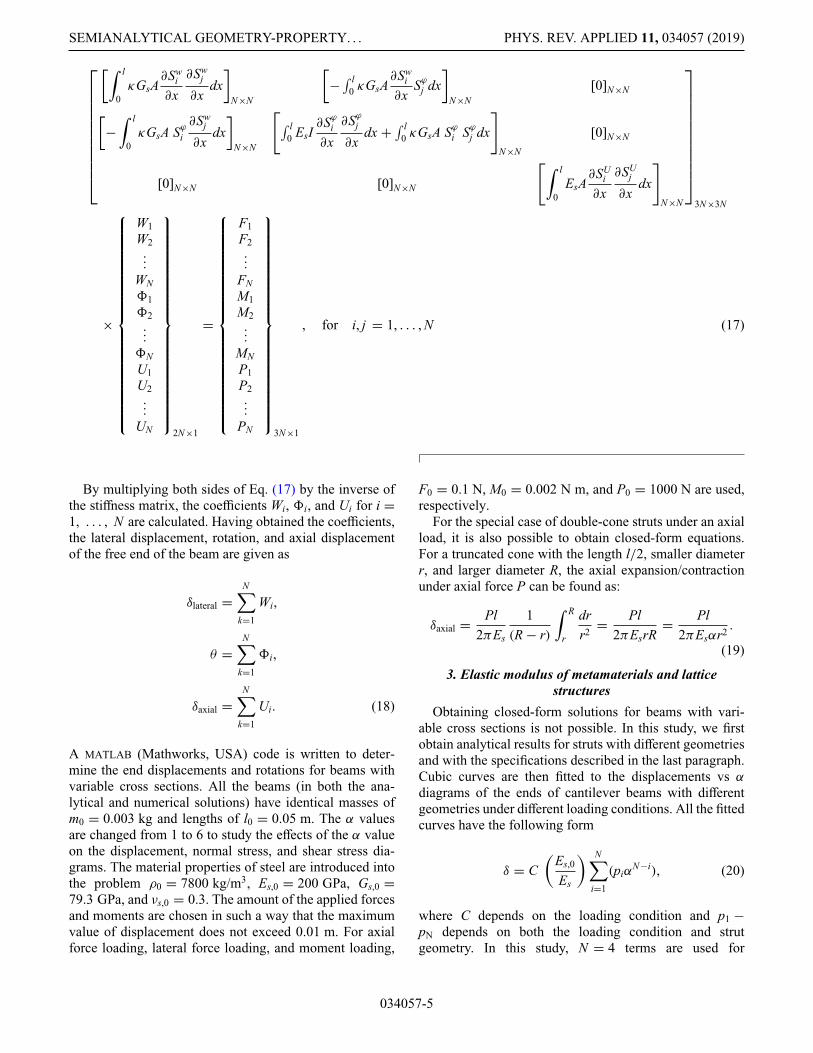
, for i, j = 1, . . . , N (17)
By multiplying both sides of Eq. (17) by the inverse ofthe stiffness matrix, the coefficients Wi, �i, and Ui for i =1, . . . , N are calculated. Having obtained the coefficients,the lateral displacement, rotation, and axial displacementof the free end of the beam are given as
δlateral =N∑
k=1
Wi,
θ =N∑
k=1
�i,
δaxial =N∑
k=1
Ui. (18)
A MATLAB (Mathworks, USA) code is written to deter-mine the end displacements and rotations for beams withvariable cross sections. All the beams (in both the ana-lytical and numerical solutions) have identical masses ofm0 = 0.003 kg and lengths of l0 = 0.05 m. The α valuesare changed from 1 to 6 to study the effects of the α valueon the displacement, normal stress, and shear stress dia-grams. The material properties of steel are introduced intothe problem ρ0 = 7800 kg/m3, Es,0 = 200 GPa, Gs,0 =79.3 GPa, and νs,0 = 0.3. The amount of the applied forcesand moments are chosen in such a way that the maximumvalue of displacement does not exceed 0.01 m. For axialforce loading, lateral force loading, and moment loading,
F0 = 0.1 N, M0 = 0.002 N m, and P0 = 1000 N are used,respectively.
For the special case of double-cone struts under an axialload, it is also possible to obtain closed-form equations.For a truncated cone with the length l/2, smaller diameterr, and larger diameter R, the axial expansion/contractionunder axial force P can be found as:
δaxial = Pl2πEs
1(R − r)
∫ R
r
drr2 = Pl
2πEsrR= Pl
2πEsαr2 .
(19)
3. Elastic modulus of metamaterials and latticestructures
Obtaining closed-form solutions for beams with vari-able cross sections is not possible. In this study, we firstobtain analytical results for struts with different geometriesand with the specifications described in the last paragraph.Cubic curves are then fitted to the displacements vs α
diagrams of the ends of cantilever beams with differentgeometries under different loading conditions. All the fittedcurves have the following form
δ = C(
Es,0
Es
) N∑i=1
(piαN−i), (20)
where C depends on the loading condition and p1 −pN depends on both the loading condition and strutgeometry. In this study, N = 4 terms are used for
034057-5

R. HEDAYATI et al. PHYS. REV. APPLIED 11, 034057 (2019)
TABLE II. Constants of the lateral and axial displacement of the struts with different geometries under different loading conditions.For our case study, the following parameters are used: m0 = 0.003 kg, ρ0 = 7800 kg/m3, l0 = 0.05 m, F0 = 0.1N , M0 = 0.002 N m,and P0 = 1000N .
C p1 p2 p3 p4
Double-cone concave (Lateral force, F)FF0
(m0
ρ0Vstrut
)2( ll0
)5
−1.4647 × 10⁻⁷ 2.1585 × 10⁻⁶ −3.9025 × 10⁻⁶ 6.3701 × 10⁻⁶
Double-cone concave (Moment, M )MM0
(m0
ρ0Vstrut
)2( ll0
)4
−1.0391 × 10⁻⁷ 1.5521 × 10⁻⁶ −2.4348 × 10⁻⁶ 3.6896 × 10⁻⁶
Double-cone concave (Axial force, P)PP0
(m0
ρ0Vstrut
)(ll0
)2
−1.7731 × 10⁻⁷ 2.099 × 10⁻⁶ 1.2912 × 10⁻⁶ 2.855 × 10⁻⁵
Double-cone convex (Lateral force, F)FF0
(m0
ρ0Vstrut
)2( ll0
)5
2.0963 × 10⁻⁷ 9.8763 × 10⁻⁷ −2.8271 × 10⁻⁷ 3.2737 × 10⁻⁶
Double-cone convex (Moment, M )MM0
(m0
ρ0Vstrut
)2( ll0
)4
7.2524 × 10⁻⁸ 5.8636 × 10⁻⁷ −5.5547 × 10⁻⁷ 2.4354 × 10⁻⁶
Double-cone convex (Axial force, P)PP0
(m0
ρ0Vstrut
)(ll0
)2
−1.7033 × 10⁻⁷ 2.2245 × 10⁻⁶ 8.2452 × 10⁻⁷ 2.8861 × 10⁻⁵
Hyperbolic concave (Lateral force, F)FF0
(m0
ρ0Vstrut
)2( ll0
)5
2.916 × 10⁻⁷ −2.5066 × 10⁻⁷ 1.3737 × 10⁻⁶ 2.4735 × 10⁻⁶
Hyperbolic concave (Moment, M )MM0
(m0
ρ0Vstrut
)2( ll0
)4
2.1674 × 10⁻⁷ −1.0061 × 10⁻⁷ 8.1761 × 10⁻⁷ 1.551 × 10⁻⁶
Hyperbolic concave (Axial force, P)PP0
(m0
ρ0Vstrut
)(ll0
)2
−2.0847 × 10⁻⁷ 3.5759 × 10⁻⁶ −1.888 × 10⁻⁶ 3.031 × 10⁻⁵
Hyperbolic convex (Lateral force, F)FF0
(m0
ρ0Vstrut
)2( ll0
)5
7.0372 × 10⁻⁷ −2.8385 × 10⁻⁶ 9.6897 × 10⁻⁶ −4.2156 × 10⁻⁶
Hyperbolic convex (Moment, M )MM0
(m0
ρ0Vstrut
)2( ll0
)4
6.6052 × 10⁻⁹ 1.2554 × 10⁻⁶ −2.1702 × 10⁻⁶ 3.5615 × 10⁻⁶
Hyperbolic convex (Axial force, P)PP0
(m0
ρ0Vstrut
)(ll0
)2
−1.5939 × 10⁻⁷ 1.9506 × 10⁻⁶ 1.2663 × 10⁻⁶ 2.8809 × 10⁻⁵
fitting and the obtained constants for different geome-tries and loading conditions are listed in Table I (forsteel). The coefficient (Es,0/Es) in Eq. (20) takes intoaccount the change in the displacement due to thechange in the elastic modulus of the bulk material whenthe bulk material has an elastic modulus other thanEs,0. The coefficient C is (F/F0)(m0/ρ0 Vstrut)
2(l/l0)5,(M/M0)(m0/ρ0 Vstrut)
2(l/l0)4, and (P/P0)(m0/ρ0 Vstrut)
(l/l0)2 for the lateral force, moment, and axial force,respectively (Table II). The steps needed for derivationof C factors can be found in the electronic supplemen-tary material accompanying the paper [25]. Subsequently,we use the semi-analytical relationships given in Eq. (20)to obtain the elastic modulus of lattice structures withcubic and diamond unit cell types. The diamond unit cellis chosen due to the fact that the pentamode mechanicalmetamaterials proposed by Milton and Cherkaev [21] arebased on the diamond unit cell. Since additive manufactur-ing of horizontal struts can be quite challenging not only inthe powder bed fusion processes [26], but, as we will seelater, also in material extrusion techniques, the cubic unitcell is chosen to highlight the manufacturability aspects.
Cube: For the structures based on the cubic unit cell,the vertical struts go under simple compression. If the
total load P is applied to each unit cell, each verti-cal strut goes under the compressive load, P. The elas-tic modulus of each unit cell is obtained by Eu.c. =Plu.c./(Au.c.δu.c.), where lu.c. = l is the dimension of theunit cell, Au.c. is the cross-section area of the unit cell,and δu.c. is the resulting displacement, which is equalto the displacement of the vertical strut δaxial. There-fore, Eu.c. = P/(lδaxial), where δaxial for each strut typeis given in Eq. (20). The semi-analytical formula forelastic modulus of the cubic structure is, therefore,given as
Eu.c.
Es= Po
Es,0l(
m0ρ0Vstrut
) (ll0
)2∑Ni=1 (piαN−i)
, (21)
where the constant p1 − pN is given in Table I for each strutgeometry. In the cubic structure, Vstrut = Vmat/3, whereVmat is the volume occupied by the material in each unitcell and is equal to Vmat = μl3, where μ is the relativedensity of the structure, which is defined as the ratio ofthe volume occupied by the material inside a unit cell Vmatto the total volume occupied by the unit cell. Introducing
034057-6

SEMIANALYTICAL GEOMETRY-PROPERTY. . . PHYS. REV. APPLIED 11, 034057 (2019)
Vstrut = μl3/3 in Eq. (21) and simplifying gives(
Eu.c.
Es
)
cube= P0ρ0μl20
3Es,0m0∑N
i=1 (piαN−i), (22)
with p1 − pN given either in the third or the sixth rowof Table II (that correspond to the axial force constantsof, respectively, concave double-cone and convex double-cone geometries).
Using Eq. (19), we can also obtain the closed-form ana-lytical relationship for the elastic modulus of cubic struc-tures with double-cone struts. By inserting Vstrut = μl3/3in Eq. (1) and squaring both sides of the equation, we have
β2 = μ
π(1 + α + α2). (23)
By replacing β = r/l in Eq. (23), we have
1r2 = π(1 + α + α2)
μl2. (24)
Substituting Eq. (24) into Eq. (19) gives the displacementin a truncated single-cone strut with length l/2 as
δTC = P(1 + α + α2)
2Esαμl. (25)
The displacement equation in a cubic unit cell is δu.c. =Pu.c.lu.c./(Au.c.Eu.c.). By setting Au.c. = l2u.c. = l2, Pu.c. = P,and δu.c. = 2δTC (note that each strut in a pentamode-likecubic structure is double cone rather than a single truncatedcone), we have
Eu.c. = P2lδTC
= αμ
(1 + α + α2). (26)
Diamond: If the external force P is applied to a struc-ture based on the diamond unit cell, there is no difference
between the loads transferred to the different struts ofthe unit cell due to the symmetry [Fig. 2(a)]. Therefore,we consider only one of the struts of the unit cell, forexample AB [Fig. 2(b)]. Strut AB carries PAB = P/4.The vertical force PAB can be decomposed into axialforce PAB,axial = (P/4) sin θ and lateral force PAB,lateral =(P/4) cos θ components, where θ = 35.26◦ [Fig. 2(c)].Due to the symmetry present between vertex A of strut ABand the corresponding strut in the neighboring unit cell,vertex A must not rotate. Similarly, due to the symmetrybetween struts AB and BC, vertex B of strut AB cannotundergo any rotation. Therefore, strut AB can be consid-ered as a cantilever beam at the end of which a lateralforce, an axial force, and a bending moment are applied.In the case of a uniform cross-section area of the struts,the rotation caused by lateral force and the moment shouldbe the same with opposite signs. Equation PABl2/(2EI) =MAl/(EI) can then be used to determine the bendingmoment as MA = (1/2)PABl cos θ [27]. In the case ofstruts with nonuniform cross sections, the noted equalitydoes not hold. We, therefore, need to introduce a coefficientγ , where γ should be obtained for each case. Therefore,for the diamond structure with double-cone struts (i.e.,α �= 1), we have MA = γ (1/2)PABl cosθ = γ (P/8)l cosθ .The total vertical displacement of the free end of strut ABis
δAB,vertical = δAB,P,axial sin θ + δAB,P,lateral cos θ
− δAB,M cos θ , (27)
where δAB,P,axial is the axial displacement in the strut dueto the axial load PAB,axial, δAB,P,lateral is the lateral displace-ment due to the lateral force PAB,lateral, and δAB,M is thelateral displacement due to the moment MA. SubstitutingEq. (20) into Eq. (27) and by considering the coefficientsgiven in Table II, the total displacement is
δAB,vertical = Es,0
Es
{[PAB,axial
P0
(m0
ρ0Vstrut
)(ll0
)2]
(sin θ)
N∑i=1
(piαN−i)force, axial +
[PAB,lateral
F0
(m0
ρ0Vstrut
)2 ( ll0
)5]
×(cos θ)
N∑i=1
(piαN−i)force,lateral −
[MA
M0
(m0
ρ0Vstrut
)2 ( ll0
)4]
(cos θ)
N∑i=1
(piαN−i)moment
}, (28)
where the subscript pi of∑N
i=1 (piαN−i) in each of the three terms can be extracted from the corresponding row of Table II.
Replacing PAB,axial = (P/4) sin θ , PAB,lateral = (P/4) cos θ , and MA = γ (P/8)l cosθ in Eq. (28) gives
δAB,vertical = Es,0
Es
{[P4 sin2θ
P0
(m0
ρ0Vstrut
)(ll0
)2]
N∑i=1
(piαN−i)force, axial +
[P4 cos2θ
F0
(m0
ρ0 Vstrut
)2( ll0
)5]
×N∑
i=1
(piαN−i)force,lateral −
[γ P
8 lcos2θ
M0
(m0
ρ0 Vstrut
)2( ll0
)4]
N∑i=1
(piαN−i)moment
}. (29)

R. HEDAYATI et al. PHYS. REV. APPLIED 11, 034057 (2019)
Since the diamond unit cell has 16 struts, Vstrut = Vmat/16and Vmat = μ l3u.c.. Therefore, Vstrut = μ l3u.c./16. Similar tothe cubic structure, the elastic modulus of each unit cellis obtained as Eu.c. = Plu.c./Au.c.δu.c.. For the diamond unitcell, lu.c. = 2
√2l cos θ , Au.c. = l2u.c., and δu.c. = 4δAB,vertical.
Therefore, Eu.c. = P4 lu.c.δAB,vertical
, which, after inserting inEq. (29), gives
Eu.c. = 1lu.c.λ
Es
Es,0, (30)
with
λ =[
sin2θ
P0
(16m0
ρ0μl3u.c.
)(ll0
)2]
N∑i=1
(piαN−i)force, axial
+[
cos2θ
F0
(16m0
ρ0μl3u.c.
)2( ll0
)5]
N∑i=1
(piαN−i)force,lateral
−[γ
lcos2θ
2M0
(16m0
ρ0μl3u.c.
)2( ll0
)4]
N∑i=1
(piαN−i)moment,
(31)
with p1 − pN given in Table II. Since the coefficients picorrespond to the curves obtained for the struts made ofstainless steel, the relative elastic modulus of the structurefor any given material is obtained as
(Eu.c.
Es
)
diamond= 1
lu.c.λEs,0. (32)
The coefficient β for the diamond unit cell can beobtained by inserting Vstrut = μl3u.c./16 into Eq. (1), whichgives
β =(
3√
2μcos3θ
π (1 + α + α2)
)1/2
. (33)
4. Yield strength of metamaterials
To obtain the yield stress, first the normal and shearstresses in the critical points of the struts generated byaxial force, lateral force, and moment are determined. Itmust be noted that yielding in the struts occurs at the pointwith the minimum cross-section area Ar = πr2 = πβ2l2.By replacing β from Eq. (1), we have
Ar = πβ2l2 = 3Vstrut
l(1 + α + α2). (34)
Cube: For the cubic structure under compression, eachstrut goes under load P, and Vstrut = μl3/3. Therefore,the maximum stress in the struts equals the stress at
the point with minimum cross-section area. As the cube-based structure consists of concave double-cone struts,the minimum cross-section area is at the middle point ofeach strut, and therefore, the initial plastic zone appears atx = l/2.
By replacing Vstrut = μl3/3 in σmax = P/Ar, we have:
σmax = (1 + α + α2)Pμl2
. (35)
When the stress applied on the lattice structure P/l2
reaches σY, the maximum local stress in the struts{[(1 + α + α2)P]/μl2} equals σY,s. A simple cross multi-plication gives
σY =σY,sP
l2
(1+α+α2)Pμl2
= σY,sμ
(1 + α + α2), (36)
or
σY
σY,S= μ
(1 + α + α2). (37)
Diamond structure with convex double-cone struts: Asdemonstrated in Figs. 7 and 8 in Sec. III A 3, both thenormal and shear stresses in the beam with convex double-cone geometry reach their maximum value at x = 0 underboth lateral force F [Figs. 7(a) and 8(a)] and moment M[Figs. 7(b) and 8(b)]. The maximum normal stress gener-ated by the normal force P also occurs at x = 0 as the beamhas the lowest cross-section area at that point.
For the diamond unit cell with convex double-conestruts, the normal force, the lateral force, and themomentum in the strut are (P/4) sin θ , (P/4) cos θ , andγ (P/8)l cos θ , respectively, where γ = 0.7 for μ = 0.1and γ = 0.56 for α = 2. Therefore, the normal stress gen-erated by the axial force at the root of the struts is givenby
σn,A = P sin θ
4Ar=
P sin θ4
3Vstrutl(1+α+α2)
= Pl(1 + α + α2) sin θ
12Vstrut
= (1 + α + α2)P sin θ
4μl2. (38)
The stress generated by the bending stress is
σn,B = MrI
= Mrπ4 r4 = 4M
πr3 = 4(γ P
8 l cos θ)
π(β3l3)
= (γ P cos θ)
2π(β3l2)= γ P cos θ
2π l2(
3 Vstrutπ l3(1+α+α2)
)3/2 . (39)
034057-8

SEMIANALYTICAL GEOMETRY-PROPERTY. . . PHYS. REV. APPLIED 11, 034057 (2019)
For a diamond unit cell with double-cone struts, Vstrut =[{μ(
2√
2l cos θ)3}
/16]
. Therefore:
σn,B = γ P cos θ
2π l2(
3√
2μ (cos θ)3
π(1+α+α2)
)3/2
= γ P cos θ
2π l2
(π(1 + α + α2)
3√
2μ (cos θ)3
)3/2
. (40)
The normal stress in the beam is the sum of both normalstresses, that is, σxx = σn,B + σn,A. On the other hand, themaximum shear stress generated by the lateral force is
τzx = 43τave, zx = 4
3P4
cos θ
Ar= P
3l(1 + α + α2) cos θ
3Vstrut
= 16P9
l(1 + α + α2) cos θ
μ(
2√
2 l cos θ)3 , =
√2
18(1 + α + α2)P
μl2 cos θ.
(41)
As noted in Eq. (8), the other stress components in thevon-Mises yield stress are neglected. Considering the axialnormal stress (σxx) and transverse shear stress (τzx) com-ponents of stress, the von-Misses stress can be obtained asfollows:
σV =√
(σn,A + σn,B)2 + 3τ 2zx. (42)
When the stress applied on the lattice structure P/l2u.c.reaches σY (i.e., the lattice structure yields), the maximumlocal stress in the struts σV equals σY,s. A simple crossmultiplication gives
σY = PσY,S
l2u.c. σV, (43)
or
σY
σY,S= P
8l2cos2θ
√(σn,B + σn,A)2 + 3τ 2
zx
, (44)
with σn,A, σn,B, and τzx given in Eqs. (38), (40), and (41).Diamond structure with concave double-cone struts:
As demonstrated in Figs. 7 and 8, both the normal andshear stresses in the beam with concave double-conegeometry reach their maximum value at x = l/2 underboth lateral force F [Figs. 7(a) and 8(a)] and moment M[Figs. 7(b) and 8(b)]. The maximum normal stress gen-erated by normal force P also occurs at x = l/2 as thebeam has the lowest cross-section area at the middle point.Therefore, the initial appearance of a plastic zone could beexpected at x = l/2 for each strut.
For the diamond unit cell with concave double-conestruts, the normal force, lateral force, and momentum inthe strut are, respectively, (P/4) sin θ , (P/4) cos θ , andγ (P/8)l cos θ , where γ = 0.84 for μ = 0.1 and γ = 0.7for α = 2. Therefore, the stress generated by the normalforce in the middle of the struts is the same as the stress atthe root of the convex double-cone structure [i.e., Eq. (38)].
The stress generated by the bending stress is
σn,B = MrI
= Mrπ4 r4 = 4M
πr3 = 4(γ P
8l2 cos θ
)
π(β3l3)
= γ P cos θ
4π l2
(π(1 + α + α2)
3√
2μ (cos θ)3
)3/2
. (45)
Similar to what was seen before, the total normal stress inthe beam is given by σxx = σn,B + σn,A.
The maximum shear stress generated by the lateral forceis the same as the one presented for the convex double-cone beam geometry [i.e., Eq. (41)]. Therefore, for the caseof a concave double-cone, Eq. (44) can also be used as longas Eq. (45) is used for σn,B instead of Eq. (40).
Buckling: In order to study the likelihood of the insta-bility of struts (beams) under axial compressive loadsapplied at the free end of the beams, the Euler’s criticalload should be determined for each beam. According tothis criterion, the critical load is the maximum load that abeam (strut) can bear without experiencing instability. Themajor load applied on the struts of diamond pentamodestructures is bending as also demonstrated by the deforma-tion of the lattice structure during the whole compressionprocedure.
For the cubic structure, however, the main type of load-ing is axial compression, which could lead to bucklinginstability. In the cube-based lattice structures, we have
Pcr = π2EsIr
(Le)2 = π2EsIr
4l2, (46)
where Pcr is the Euler’s critical load, Es is the elastic mod-ulus of the material from which the struts are made, Ir is theminimum area moment of inertia of the cross section of thestrut, and Le is the effective length of the struts. Since theaxial load is applied to the end of the cantilever beam, theeffective length equals Le = 2l. Therefore,
σcr = π2EsIr
4Arl2= π2Esr2
16 l2= π2Esβ
2
16
= π2Es
163Vstrut
π l3(1 + α + α2)= πEs
16μ
(1 + α + α2). (47)
Consequently,
σcr
σY,S= πEs
16σY,S
(σY
σY,S
), (48)
034057-9

R. HEDAYATI et al. PHYS. REV. APPLIED 11, 034057 (2019)
where (σY/σY,S) for a cube-based structure is given byEq. (37). For the polylactic acid (PLA) material, Es isaround 40 times higher than σY,S. In other words, bucklingstress is 7.81 times the yield stress. Hence, yielding occursbefore buckling.
B. Computational models
For FE modeling of beams with variable cross sections,3D structures are modeled using 8-noded brick elements(SOLID185). ANSYS implicit FE solver is used. A linearelastic material model is used for predicting the responseof the beams. Macro codes are written in ANSYS to auto-matically create, discretize, load, and obtain the requiredproperties of beams with four different beam geometriesand with different α ratios. An example of the 3D FE modelof a single beam is presented in Fig. 3(a). One of the endsof each beam is fixed in the space, while the other end isdisplaced downward by applying a point load or moment.
For numerical modeling of the unit cells, 3D structuresbased on diamond and cube unit cells are created using
(a)
(b)
(c)
FIG. 2. (a) A diamond cubic unit cell (b) the diamond cubicunit cell from front view, and (c) the loads transferred to strutAB and the resulting deformation.
(a)
(b)
FIG. 3. Two examples of the 3D FE models, which are used forevaluating the analytical solutions of the (a) single strut and (b)lattice structure.
8-noded brick elements (SOLID185). Macro codes arewritten to automatically create, discretize, load, and obtainthe required properties of cubic or diamond unit cells withconcave and convex double-cone struts. The lower faceof the unit cell is fixed in the Y direction, while the topface is displaced downward to cause 0.2% compression.An example of the diamond-based unit cell with struts hav-ing the geometry of a convex double cone is presented inFig. 3(b).
C. Experiments
Several specimens with diamond-based and cube-basedunit cells are additively manufactured. Two (convex dou-ble cone and concave double cone) of the four beamtypes (convex double cone, concave double cone, con-vex hyperbolic, concave hyperbolic) are chosen for theexperimental study. Lattice structures with three differentmicro-architectures are manufactured, cube-based latticestructures with concave double-cone struts and diamond-based lattice structures with either convex double-cone or
034057-10

SEMIANALYTICAL GEOMETRY-PROPERTY. . . PHYS. REV. APPLIED 11, 034057 (2019)
FIG. 4. A pentamode metamaterial sample specimen (μ = 0.2and α = 2).
concave double-cone struts. The cube-based lattice struc-tures with convex double-cone struts are not manufactureddue to reasons explained in the Results and Discussionssections. Among the three cases, specimens based on thediamond unit cell and with convex double-cone struts havethe microstructure of a pentamode metamaterial (Fig. 4)[7,23,24,28,29]. The relative densities of the diamond-based lattice structure (with both concave and convexdouble-cone struts) and cube-based structure are variedbetween 0.1 and 0.4 at a constant α (=2) to study theeffects of the relative density of the lattice structure onthe elastic modulus of the resulting mechanical metama-terial. In another parametric study, the ratio α is variedbetween 1 and 4 to study the effects of the α value onthe elastic modulus of the lattice structures (Fig. 5). Theparametric study on α effect is done at a relative densityof 0.1 for diamond-based structures and a relative densityof 0.4 for cube-based structures. For each design of the lat-tice structure, three specimens are manufactured and testedunder compression (66 specimens in total). The macroge-ometry of all the specimens is a cube with dimensions of8 × 8 × 8 cm3.
The samples are manufactured using Ultimaker 2+ 3Dprinters (Ultimaker, The Netherlands) that work on thebasis of fused deposition modeling (FDM). PLA fila-ments with a pearl white color from the same provider areused. The infill in all the samples is set to 100% and thelayer thickness is 200 μm. The static compression testsare performed using an INSTRON Electropulse E10000
machine with a 10-kN load cell. The compression tests areperformed in accordance with ISO standard 13314:2011,which refers to the mechanical testing of porous and cellu-lar materials. The displacement rate is fixed at 2 mm/min.The elastic modulus of the specimens is obtained by calcu-lating the slope of the stress-strain curve in the linear part.Nonporous (i.e., fully solid) cylindrical samples are madeand tested to obtain the mechanical properties of the bulkfilament. The cylinders have diameters of 12.7 mm andlengths of 25.4 mm. The mean elastic modulus obtainedfor the pearl white filament is 1.404 GPa and the meanyield stress is 35.28 MPa.
III. RESULTS
A. Single beams with variable cross sections
1. Number of terms
In the analytical solution, the number of terms of δlateral,δaxial, and θ [in Eq. (9)] is increased from k = 2 to k = 16to see at what k the results of the analytical model con-verge. The solution converged for all geometries exceptthe convex double cone for k ∼= 14 (Fig. 5). The convexdouble-cone geometry converged at k = 10. It must benoted that by increasing the number of terms to valueslarger than k = 14, small pivots are formed in the stiff-ness matrix of the beams [i.e., in Eq. (17)] due to whichthe determinant of the stiffness matrix becomes very small,causing fluctuations in the curves [see, for example, thecurve corresponding to k = 12 in Fig. 5(a)]. In each case,the converged curve (with the maximum number of termsbefore fluctuations are formed in the curve) is used for thesemi-analytical study presented in the next sections.
2. Displacement curves
The lateral displacements resulting from the lateral force(F0 = 0.1 N), the lateral displacements caused by the pointmoment (M0 = 0.002 N m), and the axial displacementsimposed by the axial load (P0 = 1000 N) for differentgeometries and α ratios are presented in Fig. 6. For thecases of lateral force and moment loadings [Figs. 6(a)and 6(b)], the numerical and analytical results show a gen-erally good agreement for all α values. The only exceptionis the concave double-cone geometry under moment load-ing for which there are larger discrepancies between theanalytical and numerical solutions for α ratios larger than3 [Fig. 6(b)]. For the case of axial loading, the numericaland analytical curves are very close for all the geometries[Fig. 6(c)]. As expected, the curves corresponding to dif-ferent geometries coincide at α = 1 (Fig. 6), that is, whenthe maximum and minimum radii are the same and all strutshapes reduce to cylinders (r = R).
Increasing the α ratio increases the resulting displace-ment in all the cases. For example, in the case of lateralforce loading [Fig. 6(a)], the lateral displacements of both
034057-11

R. HEDAYATI et al. PHYS. REV. APPLIED 11, 034057 (2019)
(a) (b)
(c) (d)
FIG. 5. Effect of number of terms on the resulting lateral displacement at the free end of a cantilever beam with (a) concave double-cone, (b) convex double-cone, (c) concave hyperbolic, and (d) convex hyperbolic geometries.
the concave hyperbolic and concave double-cone geome-tries in α = 3 are, respectively, around 2 and 4 times largerthan that of the cylindrical geometry. Similar values areobserved for the convex hyperbolic and convex double-cone geometries. In the case of point moment loading[Fig. 6(b)], at α = 3, the lateral displacement of all the fourgeometries is about 3 times larger than of the cylindricalgeometry. As for axial loading [Fig. 6(c)], all the geome-tries except for the concave hyperbolic geometry showsimilar behaviors. At α = 3, for example, the extensionsof the convex hyperbolic, concave double-cone, and con-vex double-cone geometries are about 1.45 times that of asimple cylinder. At α = 3, the axial extension of the con-cave hyperbolic geometry is about 1.67 times the valuesfound for a simple cylinder.
3. Normal stress distribution
The normal and shear stresses calculated for the outerfiber of the struts along the strut length for both loading
types of lateral force and moment are presented in Figs. 7and 8, respectively. The analytical and numerical stressespractically overlap, which is why only the analytical resultsare plotted in Figs. 7 and 8. Under both lateral forceand moment loads, the stress value is maximum at thecenter of beam for all the concave geometries (Fig. 7).The only exception is the concave hyperbolic geometryunder lateral force [Fig. 7(c)]. Moreover, the normal stressdistribution is symmetrical with respect to the center ofthe beams in all the beam geometries and loading con-ditions. The only exceptions are the convex geometriesunder lateral force, which show a maximum normal stressat x = 0 and a minimum normal stress at x = l [Figs. 7(a)and 7(c)].
For beams with α = 6 and under lateral force loading,the concave double-cone geometry shows the maximumnormal stress (about 11 MPa) [Fig. 7(a)]. Again, for beamswith α = 6 under moment loading, the maximum normalstress belongs to both the concave and convex double-conegeometries (8.5 and 7 MPa, respectively) [Fig. 7(b)], while
034057-12

SEMIANALYTICAL GEOMETRY-PROPERTY. . . PHYS. REV. APPLIED 11, 034057 (2019)
(a)
(b)
(c)
FIG. 6. (a) Lateral displacement due to lateral force, (b) lateraldisplacement caused by point moment, and (c) axial displace-ment imposed by axial load for different geometries and α ratiosin constant mass of the strut.
the maximum normal stress in the hyperbolic geometry isless than 3 MPa [Fig. 7(d)].
4. Shear stress distribution
The shear stress exhibits a somewhat different behav-ior (Fig. 8). The shear stress in the concave double-cone
geometry (under both lateral force and moment loads) isfound to suddenly change in the middle of the strut from anegative value to a positive value with the same amplitude[Figs. 8(a) and 8(b)]. The concave hyperbolic geometryalso shows the change of shear stress from a negativevalue to a positive value, but in a gradual way [Figs. 8(c)and 8(d)]. Under both lateral force and moment loadings,the maximum shear stress in the concave double-conegeometry is about 6 times of that in the concave hyper-bolic geometry. Under lateral force loading, the maximumshear stress for the convex beams occurs at the clampedend of the beam [Figs. 8(a) and 8(c)], while under momentloading, the maximum shear stress for the same type ofbeams occurs at both the free and clamped ends of thebeam (Fig. 8).
B. Mechanical metamaterials
Deformation: Under compression, all the diamond-based lattice structures show three-stage stress-straincurves. In the first stage, the curve is linear. After the stresslevel reaches a local maximum, it decreases to about halfof the initial maximum value. In the second stage, thestrain greatly increases with very small accumulations inthe stress value (the stress at this stage is known as theplateau stress). In the final stage, the stress-strain curvealso shows a second linear part (known as the densifica-tion regime). In all the diamond-based structures, after thestress reaches the initial maximum stress, 45◦ failure bandsare formed (Fig. 9) after which the stress value is decreasedto half the value of the initial maximum stress. In the cube-based structures, the structures fail after a row of unit cellsare buckled and fractured without showing any 45◦ failureband. As a result, the cube-based structures do not showthe plateau and densification parts in their stress-straincurves.
Elastic modulus: The effects of the relative densityμ and α ratio on the relative elastic modulus of bothdiamond- (Fig. 10) and cube-based (Fig. 11) structures isalso investigated. As expected, increasing the relative den-sity, while keeping the α ratio (α = 2) constant, increasesthe elastic modulus in both the diamond- and cube-basedstructures (Figs. 10–12). The numerical and analyticalresults are close, especially for small values of relativedensity [Figs. 10(a) and 10(b) and 11(a)]. The γ valuesthat are obtained for Eq. (32) in such a way that analyticalcurves approach the experimental and numerical ones arepresented in the titles of each plot in Fig. 10. The numer-ical and analytical results are less than 10% different evenat relative densities as large as 30% (Figs. 10 and 11).As compared to the diamond-based structure, the cube-based structure shows a much higher elastic modulus. Forexample, at μ = 0.2 and α = 2, the elastic modulus of thestructure with cubic unit cell is more than 8 times of thatof the structure with the diamond-type unit cell.
034057-13

R. HEDAYATI et al. PHYS. REV. APPLIED 11, 034057 (2019)
(a) (b)
(c) (d)
Double cone (Lateral force) Double cone (Moment)
Hyperbolic (Lateral force) Hyperbolic (Moment)
FIG. 7. The normal stress value at the outer fiber of the cantilever beam for (a) double-cone geometries under lateral force, (b)double-cone geometries under moment, (c) hyperbolic geometries under lateral force, and (d) hyperbolic geometries under moment.
The effects of α value on the obtained elastic mod-ulus values is more interesting, because the pentamodemetamaterials investigated in this study are suggested assubstitutes for currently used porous structures in whichthe strut cross-section areas are uniform. The effects ofthe α value are investigated at a constant relative den-sity of μ = 0.1 for the diamond-based lattice structure[Figs. 10(c) and 10(d)] and μ = 0.4 for the cube-basedlattice structures [Fig. 11(b)]. The analytical, numerical,and experimental results in both cube- and diamond-basedstructures are close [Figs. 10(c) and 10(d) and 11(b)]. Inboth the cube- and diamond-based structures, increasingthe α value decreases the elastic modulus. As comparedto the cube-based structures, increasing the α value hasa higher impact on the elastic modulus of the diamond-based structures, especially at small values of α (i.e., moreuniform struts). Increasing the α ratio from α = 1 to α =4 decreases the analytically obtained elastic modulus ofthe diamond-based and cube-based structures (with con-vex double-cone struts) for, respectively, 92.24% (about1/13) [Fig. 10(c)] and 44% (about half) [Fig. 11(b)].
Increasing the relative density of the diamond-based andcube-based lattice structures (with convex double-conestruts) from 0.1 to 0.3 increases the analytical relative elas-tic modulus by 636% [Fig. 10(a)] and 300% [Fig. 11(a)],respectively.
Yield stress: Since the maximum load applied by thecompression test machine is 10 kN, among all the cube-based structures, only two cases of (μ = 0.1 and α = 2)and (μ = 0.4 and α = 4) yield. For the other cases, theexperiment is ended before the lattice structures yield.The closed-form analytical and experimental yield stressesfor the cube-based and pentamode diamond-based latticestructures are compared to each other in Fig. 12. Similartrends to that observed for the elastic modulus curves isobserved for the yield stress. In other words, increasingthe relative density at constant α ratio (α = 2) increasesthe relative yield strength, and increasing the α ratio ata constant relative density (μ = 0.1 for a diamond-basedstructure and μ = 0.4 for a cube-based structure) decreasesthe relative yield strength. For the diamond-based struc-ture, there is a good agreement between the analytical and
034057-14

SEMIANALYTICAL GEOMETRY-PROPERTY. . . PHYS. REV. APPLIED 11, 034057 (2019)
(a) (b)
(c) (d)
Double cone (Lateral force) Double cone (Moment)
Hyperbolic (Lateral force) Hyperbolic (Moment)
FIG. 8. The shear stress value at the outer fiber of the cantilever beam for (a) double-cone geometries under lateral force, (b)double-cone geometries under moment, (c) hyperbolic geometries under lateral force, and (d) hyperbolic geometries under moment.
experimental results. For the cube-based structure withμ = 0.1 and α = 2, the measured experimental relativeyield stress is much lower than the value predicted by theanalytical relationships. As is also confirmed by experi-ments, this can be due to the fact that at very low valuesof the relative density (i.e., μ = 0.1), due to irregularitiesin the cross-section area, buckling occurs much earlier thanwhat is predicted analytically. In other words, the absolutesize of the manufacturing irregularities (i.e., variations inthe dimensions of the cross section of the struts) is similarregardless of the relative density. However, in low rela-tive densities, the relative importance of the manufacturingirregularities is much higher than when the relative den-sity, and thus, the dimensions of the cross section are muchhigher.
IV. DISCUSSIONS
The results show that for constant mass, increasing theα ratio in beams with variable cross sections increasesthe maximum normal stress (Fig. 7), maximum shear
stress (Fig. 8), and the lateral displacement at the freeend of the cantilever beam (Fig. 6). Therefore, a 3Dlattice structure with struts having a variable cross section
FIG. 9. Formation of 45◦ deformation bands in pentamodemetamaterial (The failure bands are marked by red lines.).
034057-15

R. HEDAYATI et al. PHYS. REV. APPLIED 11, 034057 (2019)
(a) (b)
(c) (d)
FIG. 10. Effect of relative density on the relative elastic modulus of diamond pentamode structures with (a) convex and (b) concavedouble-cone struts and constant α ratio (α = 2). Effect of α ratio on the relative elastic modulus of diamond pentamode structures with(c) convex and (d) concave double-cone struts and constant relative density (μ = 0.1). The γ value used for each case is shown in thetitle of each plot.
is probably more susceptible to failure under externalforces as compared to a lattice structure with uniformcross-section area and similar mass. As a good exam-ple of such structures, 3D pentamode metamaterial lat-tice structures (with struts having convex double-conegeometry) as well as two other pentamode-like latticestructures (diamond-based structures with concave dou-ble cones and cube-based lattice structures with concavedouble cones) are manufactured and tested. The antici-pated behavior is observed in the 3D structures as well.There are two main manufacturing limitations that mustbe considered in such structures. First, although it ispossible to additively manufacture diamond-based struc-tures with convex double cones, it is not possible toadditively manufacture cube-based structures with con-vex double cones without use of internal support bridges.This is because in the horizontal struts of the cube-based lattice structures with convex double cone, the partwith the maximum diameter is printed first. Since that
part is not supported by previously printed layers, thatlayer falls down. Other manufacturing techniques suchas multimaterial additive manufacturing techniques withwater-soluble support material or a powder-bed diffusiontechnique do not have such limitations, since the eas-ily removable support material holds the initially printedlarge-diameter parts of the horizontal struts. The otherproblem associated with the FDM technique in manu-facturing of pentamode and pentamode-like structures isthat when the cross-section area of the struts is verysmall, the quality of the print severely decreases, andseveral pores are created in the part with the lowerdiameter.
It has been shown in previous studies [24,28,29] thatthe elastic modulus of very low-density pentamode meta-materials (with convex double cones) are independentfrom their relative density and the maximum diameterof the struts, and the elastic modulus is only depen-dent on the diameter of the touching region in the
034057-16

SEMIANALYTICAL GEOMETRY-PROPERTY. . . PHYS. REV. APPLIED 11, 034057 (2019)
(a)
(b)
FIG. 11. (a) Effect of relative density on the relative elas-tic modulus of cube-based structures with concave double-conestruts and constant α ratio (α = 2). (b) Effect of α ratio on therelative elastic modulus of cube-based structures with concavedouble-cone struts and constant relative density (μ = 0.4).
vertices [29]. The pentamode metamaterials manufac-tured and studied here have relative densities largerthan 0.1. Due to the limitations of the FDM technique,mechanical materials with very small relative densitiescannot be manufactured. Studying the noted statementusing the analytical relationships obtained in this paperis also not possible since our analytical relationshipsare functions of the small diameter of the struts d =2r and not the diameter of the struts at the touch-ing region dt = 2rt. Using other additive manufactur-ing techniques, manufacturing very low-density penta-mode metamaterials is feasible. For example, in ourother study [7], several Ti-6Al-4V pentamode metama-terials with different relative densities (between 0.84%and 2.24%), but with the same touching region diameter,were made and tested under compression. The test results
demonstrated their very close elastic modulus and yieldstress.
The analytical solutions obtained for struts with variablecross sections are used for obtaining the semi-analyticalrelationships for pentamode and pentamode-like mechan-ical metamaterials. The relationships obtained for othertypes of struts [Eq. (20) along with Table II] can alsobe used for obtaining semi-analytical relationships forthe structures having other strut types as well as withother unit cell types, such as cube [30,31], rhombicdodecahedron [19,32], truncated cube [33], diamond [27],tetrakaidecahedrons [15,34], rhombicuboctahedron [18],and truncated cuboctahedron [20]).
The analytical and numerical results obtained in thisstudy show that among the five proposed strut geometrieshaving the same volume, the highest displacements belongto convex hyperbolic under lateral force and concavehyperbolic under axial force and point moment (Figs. 6and 8). This suggests that the hyperbolic strut types areusually less stiff than double-cone struts. Moreover, in allloading cases, the concave double-cone geometry exhibitssome of the lowest values of displacement. Therefore, itseems that structures having concave double-cone strutsare the stiffest among the structures with the same unit celltype, but with other strut types. This is partly shown inthe diamond-based lattice structures with concave and con-vex double cones [compare Figs. 10(a) and 10(b), compareFigs. 10(c) and 10(d)]. For future studies, it is suggestedthat the mechanical properties of mechanical metamateri-als with the same unit cell types but with different struttypes be compared with each other to see which structureshave the highest stiffness, strength, and energy absorptioncapacities.
One of the recent important applications of 3D latticestructures is their use as bone-substituting biomaterials. Inbone-substituting biomaterials, the stiffness of the implantis of great importance. If the stiffness of the implant ismuch larger than that of natural bones, it transfers mostof the loads applied to the implanted bone and unloadsthe natural bone (the stress-shielding phenomenon). Asa result, after a while, bone resorption occurs, leadingto implant loosening. Therefore, it has been suggestedto manufacture implants with stiffness distribution similarto the natural bone [35,36]. Lattice structures with vari-ous types of nonuniform cross sections could be used tomimic the spatial distribution of the mechanical proper-ties of the bone tissue, while satisfying other importantdesign requirements [37] such as pore shape [38], cur-vature [39], and permeability [40]. Using the same unitcell type throughout the implant while changing the crosssection design has the advantage that connectivity betweenthe various unit cells is straightforward. That is not the casewhen different types of unit cells have to be used in order tomimic the spatial distribution of the mechanical propertiesof the bone tissue.
034057-17

R. HEDAYATI et al. PHYS. REV. APPLIED 11, 034057 (2019)
(a) (b)
(c) (d)
(e) (f)
FIG. 12. The effects of relative density and α ratio on the relative yield strength for (a-b) cubic, and (c-f) diamond pentamodestructures.
V. CONCLUSIONS
In this study, five different types of symmetrical struts,namely simple cylinder, concave double cone, convex dou-ble cone, concave hyperbolic, and convex hyperbolic, areconsidered. We then derive semi-analytical relationships
to describe the mechanical response of the beams andlattice structures (diamond-type, cube-type) based on theabove-mentioned types of cross sections. Comparison ofthe analytical, numerical, and experimental results demon-strate the accuracy of the semi-analytical relationshipspresented for the elastic modulus and yield strength of
034057-18

SEMIANALYTICAL GEOMETRY-PROPERTY. . . PHYS. REV. APPLIED 11, 034057 (2019)
these biomaterials. In both cube- and diamond-based struc-tures, increasing the α value at constant relative densitydecreases the elastic modulus and yield strength.
[1] J. Valentine, S. Zhang, T. Zentgraf, E. Ulin-Avila, D. A.Genov, G. Bartal, and X. Zhang, Three-dimensional opticalmetamaterial with a negative refractive index, Nature 455,376 (2008).
[2] Y. Zhao, M. Belkin, and A. Alù, Twisted optical metamate-rials for planarized ultrathin broadband circular polarizers,Nat. Commun. 3, 870 (2012).
[3] D. Torrent and J. Sánchez-Dehesa, Acoustic metamaterialsfor new two-dimensional sonic devices, New J. Phys. 9, 323(2007).
[4] H. Chen and C. Chan, Acoustic cloaking in three dimen-sions using acoustic metamaterials, Appl. Phys. Lett. 91,183518 (2007).
[5] A. A. Zadpoor, Mechanical meta-materials, Mater. Horiz.3, 371 (2016).
[6] J. H. Lee, J. P. Singer, and E. L. Thomas, Micro-/nanostructured mechanical metamaterials, Adv. Mater. 24,4782 (2012).
[7] R. Hedayati, A. Leeflang, and A. Zadpoor, Additively man-ufactured metallic pentamode meta-materials, Appl. Phys.Lett. 110, 091905 (2017).
[8] R. Hedayati, M. Mirzaali, L. Vergani, and A. Zadpoor,Action-at-a-distance metamaterials: Distributed local actu-ation through far-field global forces, APL Mater. 6, 036101(2018).
[9] K. E. Evans and A. Alderson, Auxetic materials: functionalmaterials and structures from lateral thinking!, Adv. Mater.12, 617 (2000).
[10] R. Gatt, L. Mizzi, J. I. Azzopardi, K. M. Azzopardi, D.Attard, A. Casha, J. Briffa, and J. N. Grima, Hierarchi-cal auxetic mechanical metamaterials, Sci. Rep. 5, 8395(2015).
[11] H. M. Kolken, S. Janbaz, S. M. Leeflang, K. Lietaert, H.H. Weinans, and A. A. Zadpoor, Rationally designed meta-implants: a combination of auxetic and conventional meta-biomaterials, Mater. Horiz. 5, 28 (2018).
[12] M. Mirzaali, R. Hedayati, P. Vena, L. Vergani, M. Strano,and A. Zadpoor, Rational design of soft mechanical meta-materials: Independent tailoring of elastic properties withrandomness, Appl. Phys. Lett. 111, 051903 (2017).
[13] R. Lakes and K. Wojciechowski, Negative compressibility,negative Poisson’s ratio, and stability, Phys. Status Solidi B245, 545 (2008).
[14] Z. G. Nicolaou and A. E. Motter, Mechanical metamaterialswith negative compressibility transitions, Nat. Mater. 11,608 (2012).
[15] X. Zheng, H. Lee, T. H. Weisgraber, M. Shusteff, J.DeOtte, E. B. Duoss, J. D. Kuntz, M. M. Biener, Q. Ge,J. A. Jackson, S. O. Kucheyev, N. X. Fang, and C. M.Spadaccini, Ultralight, ultrastiff mechanical metamaterials,Science 344, 1373 (2014).
[16] R. Lakes and W. Drugan, Dramatically stiffer elastic com-posite materials due to a negative stiffness phase?, J. Mech.Phys. Solids 50, 979 (2002).
[17] R. S. Lakes, T. Lee, A. Bersie, and Y. Wang, Extremedamping in composite materials with negative-stiffnessinclusions, Nature 410, 565 (2001).
[18] R. Hedayati, M. Sadighi, M. Mohammadi-Aghdam, and A.A. Zadpoor, Mechanics of additively manufactured porousbiomaterials based on the rhombicuboctahedron unit cell, J.Mech. Behav. Biomed. Mater. 53, 272 (2016).
[19] S. Babaee, B. H. Jahromi, A. Ajdari, H. Nayeb-Hashemi,and A. Vaziri, Mechanical properties of open-cell rhom-bic dodecahedron cellular structures, Acta Mater. 60, 2873(2012).
[20] R. Hedayati, M. Sadighi, M. Mohammadi-Aghdam, and A.Zadpoor, Mechanical behavior of additively manufacturedporous biomaterials made from truncated cuboctahedronunit cells, Int. J. Mech. Sci. 106, 19 (2016).
[21] G. W. Milton and A. V. Cherkaev, Which elasticity tensorsare realizable?, J. Eng. Mater. Technol. 117, 483 (1995).
[22] A. N. Norris, Acoustic metafluids, J. Acoust. Soc. Am. 125,839 (2009).
[23] C. N. Layman, C. J. Naify, T. P. Martin, D. C. Calvo,and G. J. Orris, Highly Anisotropic Elements for Acous-tic Pentamode Applications, Phys. Rev. Lett. 111, 024302(2013).
[24] M. Kadic, T. Bückmann, N. Stenger, M. Thiel, and M.Wegener, On the practicability of pentamode mechanicalmetamaterials, Appl. Phys. Lett. 100, 191901 (2012).
[25] See Supplemental Material at http://link.aps.org/supplemental/10.1103/PhysRevApplied.11.034057 for steps requiredto derive the factors C in Eq. (20).
[26] R. Wauthle, B. Vrancken, B. Beynaerts, K. Jorissen, J. Sch-rooten, J.-P. Kruth, and J. Van Humbeeck, Effects of buildorientation and heat treatment on the microstructure andmechanical properties of selective laser melted Ti6Al4Vlattice structures, Addit. Manuf. 5, 77 (2015).
[27] S. Ahmadi, G. Campoli, S. Amin Yavari, B. Sajadi, R.Wauthlé, J. Schrooten, H. Weinans, and A. A. Zadpoor,Mechanical behavior of regular open-cell porous biomate-rials made of diamond lattice unit cells, J. Mech. Behav.Biomed. Mater. 34, 106 (2014).
[28] M. Kadic, T. Bückmann, R. Schittny, P. Gumbsch, and M.Wegener, Pentamode Metamaterials With IndependentlyTailored Bulk Modulus and Mass Density, Phys. Rev. Appl.2, 054007 (2014).
[29] R. Schittny, T. Bückmann, M. Kadic, and M. Wegener,Elastic measurements on macroscopic three-dimensionalpentamode metamaterials, Appl. Phys. Lett. 103, 231905(2013).
[30] J. Parthasarathy, B. Starly, S. Raman, and A. Christensen,Mechanical evaluation of porous titanium (Ti6Al4V) struc-tures with electron beam melting (EBM), J. Mech. Behav.Biomed. Mater. 3, 249 (2010).
[31] L. J. Gibson and M. F. Ashby, Cellular Solids: Structureand Properties (Cambridge University Press, Cambridge,1997).
[32] R. Hedayati, M. Sadighi, M. Mohammadi-Aghdam, andA. A. Zadpoor, Computational prediction of the fatiguebehavior of additively manufactured porous metallic bio-materials, Int. J. Fatigue 84, 67 (2016).
[33] R. Hedayati, M. Sadighi, M. Mohammadi-Aghdam, andA. A. Zadpoor, Mechanical properties of regular porous
034057-19

R. HEDAYATI et al. PHYS. REV. APPLIED 11, 034057 (2019)
biomaterials made from truncated cube repeating unit cells:Analytical solutions and computational models, Mater. Sci.Eng. C 60, 163 (2016).
[34] W. Warren and A. Kraynik, Linear elastic behavior of alow-density Kelvin foam with open cells, J. Appl. Mech.64, 787 (1997).
[35] F. Bobbert, K. Lietaert, A. A. Eftekhari, B. Pouran, S.Ahmadi, H. Weinans, and A. Zadpoor, Additively man-ufactured metallic porous biomaterials based on minimalsurfaces: A unique combination of topological, mechani-cal, and mass transport properties, Acta Biomater. 53, 572(2017).
[36] A. A. Zadpoor and J. Malda, Additive manufacturing ofbiomaterials, tissues, and organs, Ann. Biomed. Eng. 45,1 (2017).
[37] X. Wang, S. Xu, S. Zhou, W. Xu, M. Leary, P. Choong, M.Qian, M. Brandt, and Y. M. Xie, Topological design and
additive manufacturing of porous metals for bone scaffoldsand orthopaedic implants: a review, Biomaterials 83, 127(2016).
[38] R. Hedayati, S. M. Ahmadi, K. Lietaert, B. Pouran, Y.Li, Harrie Weinans, C. D. Rans, and A. A. Zadpoor, Iso-lated and modulated effects of topology and material typeon the mechanical properties of additively manufacturedporous biomaterials, J. Mech. Behav. Biomed. Mater. 79,254 (2018).
[39] A. A. Zadpoor, Bone tissue regeneration: the role of scaf-fold geometry, Biomater. Sci. 3, 231 (2015).
[40] S. Van Bael, Y. C. Chai, S. Truscello, M. Moesen, G. Ker-ckhofs, H. Van Oosterwyck, J.-P. Kruth, and J. Schrooten,The effect of pore geometry on the in vitro biological behav-ior of human periosteum-derived cells seeded on selectivelaser-melted Ti6Al4V bone scaffolds, Acta Biomater. 8,2824 (2012).
034057-20