semiconductors. direct bandgap semiconductors (gaas, ingaas, ingaasp) the minimum of cb is directly...
TRANSCRIPT
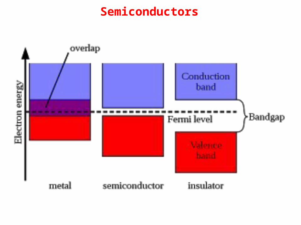
Semiconductors
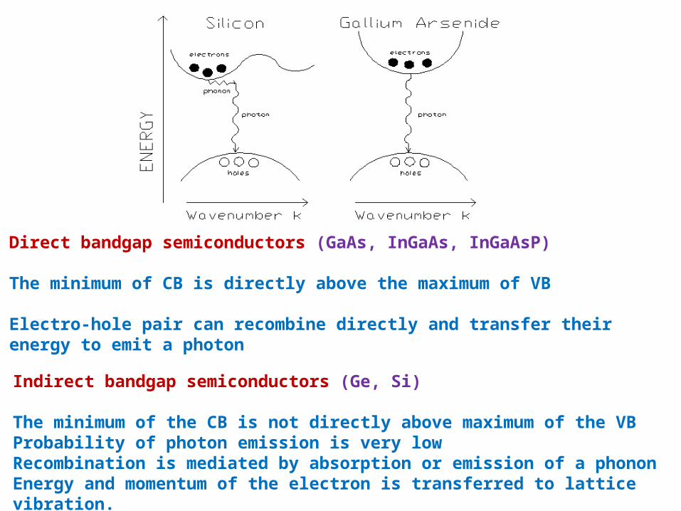
Direct bandgap semiconductors (GaAs, InGaAs, InGaAsP)
The minimum of CB is directly above the maximum of VB
Electro-hole pair can recombine directly and transfer their energy to emit a photon
Indirect bandgap semiconductors (Ge, Si)
The minimum of the CB is not directly above maximum of the VBProbability of photon emission is very low Recombination is mediated by absorption or emission of a phononEnergy and momentum of the electron is transferred to lattice vibration.
Semiconductor LASER
Direct Bandgap Semiconductor
Large possibility for direct recombination of hole and electron emitting a photon
Indirect Bandgap Semiconductor
Direct recombination of hole and electron is not possibleThere is no photon emission
GaAs - direct bandgap material – Used to make LEDs and LASER
Wavelength of the emitted light depends upon the bandgap

Pure Semiconductor

n-type semiconductor p-type semiconductor

Energy band diagram of n-type and p-type semiconductors

Energy band diagram of p-n junction at thermal equilibrium
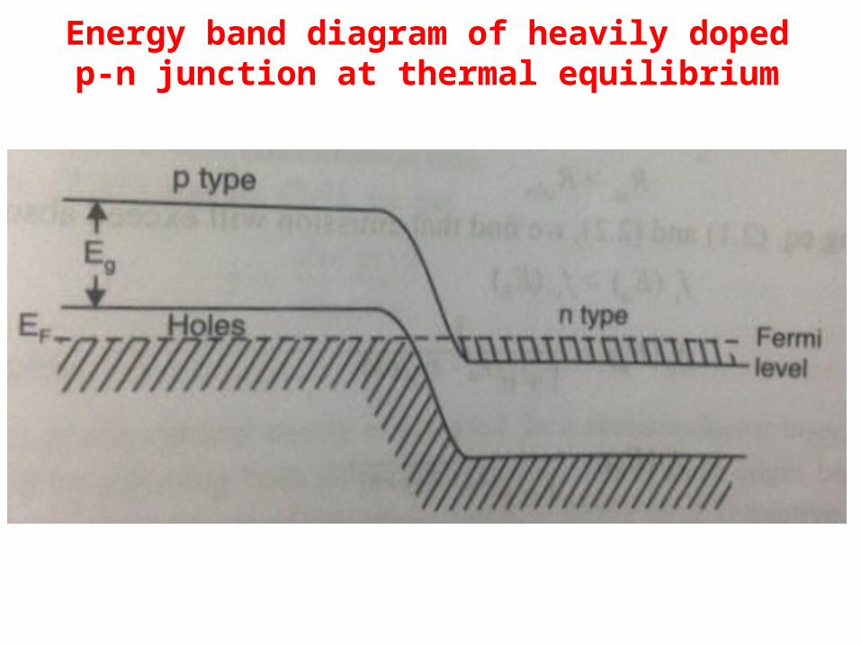
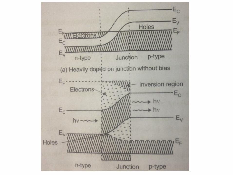
Energy band diagram of heavily doped p-n junction at thermal equilibrium

Semiconductor LASER (GaAs Diode LASER)
Active Medium
GaAs p-n junction diode
Doping Materials
p-type (Ge) & n-type (Te)
GaAs has high refractive index Reflectance at the material-air interface is large (External mirrors are not necessary)
Can give laser output with a wavelength 0.85 μm in pulsed mode

GaAs Laser - Working
Without any bias, there will be less number of electron-hole pairs in the junction region
1. Population inversion – Injection of electrons across the junction from n-doped region to the p-doped region by forward bias
2. Excess minority electrons in the p-region and excess minority holes in the n-region
3. Population inversion of minority carriers
4. When relatively large current is passed through the junction to provide excitation, the direction recombination process is efficient
5. Emitted photons increase the rate of recombination of injected electrons & holes – Thus more number of photons are produced
GaAs Laser - Working
6. Emitted photons from induced recombinations have same phase and frequency as that of the original inducing photons (We have stimulated emission of radiation along the p-n junction)
7. Wavelength of the emitted radiation depends upon concentration of donor and acceptor atoms in GaAs
8. When the donor and acceptor concentrations are about 1024 atoms/m3, the emitted wavelengths are 0.9020, 0.8425 and 0.8370 μm
9. Efficiency of laser emission increases when we cool the GaAs diode
10. In the reverse bias, no carrier injection takes place and no light emission
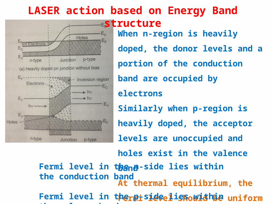
LASER action based on Energy Band structure
When n-region is heavily doped, the donor
levels and a portion of the conduction
band are occupied by electrons
Similarly when p-region is heavily doped,
the acceptor levels are unoccupied and
holes exist in the valence band
At thermal equilibrium, the Fermi level
should be uniform in the junction region
Fermi level in the n-side lies within the conduction band
Fermi level in the p-side lies within the valence band

LASER action based on Energy Band structure
When the forward bias is applied, the energy
levels shift and junction band diagram is
altered
Electrons and holes are injected across the
depletion region existing at the junction
The width of the depletion region decreases
and the minority carrier concentration in this
transition region increases exponentially
At lower threshold current, recombination of electrons and holes leads to
spontaneous emission
When the current increases, the transition region has high concentration of
electrons and holes (population inversion)
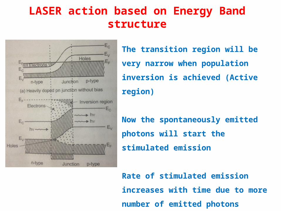
LASER action based on Energy Band structure
The transition region will be very narrow when
population inversion is achieved (Active region)
Now the spontaneously emitted photons will
start the stimulated emission
Rate of stimulated emission increases with
time due to more number of emitted photons
(Amplification of light)
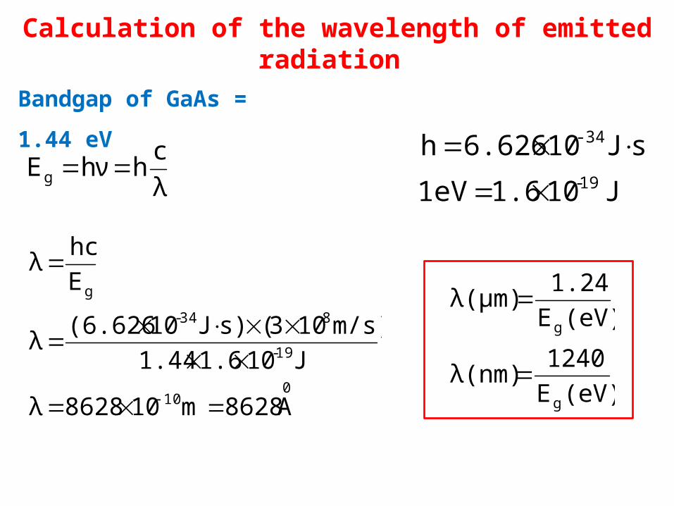
Calculation of the wavelength of emitted radiation
Bandgap of GaAs = 1.44 eV
λ
chhνEg
J 10 1.6 eV 1
sJ 10 6.626h19-
-34
010
19-
834-
g
A8628m108628λ
J101.61.44
m/s)103() sJ10 (6.626λ
E
hcλ
(eV)E
1240λ(nm)
(eV)E
1.24λ(μm)
g
g
Drawbacks of homo-junction lasers
1. Threshold current density is very large (400 A/mm2)
2. Only pulsed mode output is obtained
3. Laser output has large beam divergence
4. Poor coherence and poor stability
5. Electromagnetic field confinement is poor

Peak emission wavelength of GaAsP diode laser is 1.55 μm
What is its band gap?
eV 0.8μm 1.55
1.24
λ(μm)
1.24(eV)E
(eV)E
1.24λ(μm)
g
g
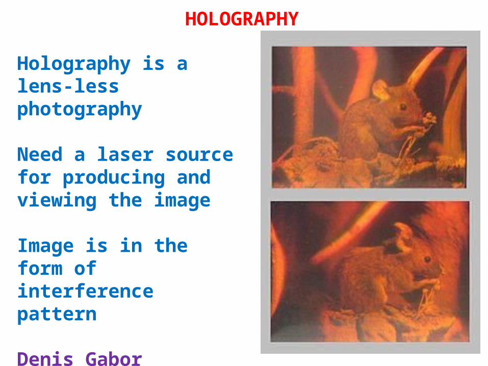
HOLOGRAPHY
Holography is a lens-less photography
Need a laser source for producing and viewing the image
Image is in the form of interference pattern
Denis Gabor developed the phenomenon of holography

Principle of Holography
Holography is based on the principle of interference
Coherent light waves are needed (laser source)
Laser beam is split into two beams A and B using a beam splitter S
Beam A recognizes the object O and a part of light scattered by the object (object beam) falls on a photographic plate P
Reflected beam B (reference beam) also falls on the photographic plate
Superposition of reference and object beams produces an interference pattern and the pattern is recorded on the plateThe developed plate is called as Holograph
Principle of Holography
Conventional Photography
Negative is made first and a positive print is produced later using negative
Positive print is only a 2-D record of light intensity received from a 3-D object
It contains information about the square of the amplitude of the light wave that produced the image but information about the phase of the light is not recorded
Holography
Both the intensity and phase of the light waves are recorded and when viewed, the photograph shows a 3-D image of the object
Construction (Generation) of a Hologram
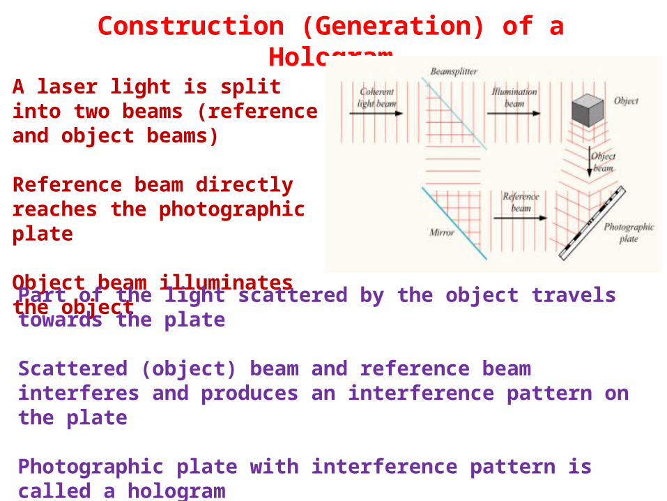
A laser light is split into two beams (reference and object beams)
Reference beam directly reaches the photographic plate
Object beam illuminates the object
Part of the light scattered by the object travels towards the plate
Scattered (object) beam and reference beam interferes and produces an interference pattern on the plate
Photographic plate with interference pattern is called a hologram
The hologram is developed, fixed and stored
Construction (Generation) of a Hologram
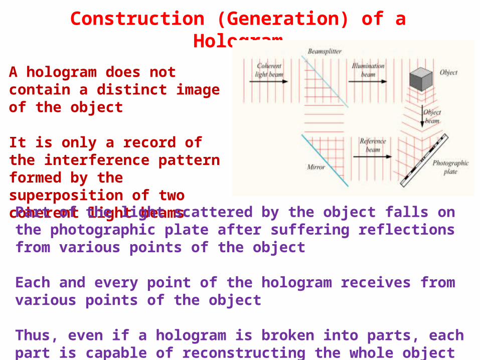
A hologram does not contain a distinct image of the object
It is only a record of the interference pattern formed by the superposition of two coherent light beams
Part of the light scattered by the object falls on the photographic plate after suffering reflections from various points of the object
Each and every point of the hologram receives from various points of the object
Thus, even if a hologram is broken into parts, each part is capable of reconstructing the whole object

Reconstruction of a Hologram
In the reconstruction process, the hologram is illuminated by laser beam
This beam is called reconstruction beam
This beam is identical to reference beam used in construction of hologram
The reconstruction beam illuminates the hologram at the same angle as the reference beam
The hologram acts as a diffraction grating and the reconstruction beam will undergo phenomenon of diffraction during passage through the hologram
The reconstruction beam after passing through the hologram produces a real as well as virtual image of the object

Reconstruction of a Hologram
The virtual image is formed behind the hologram at the original site of the objectThe real image is formed in front of the hologram
Reconstruction of a Hologram
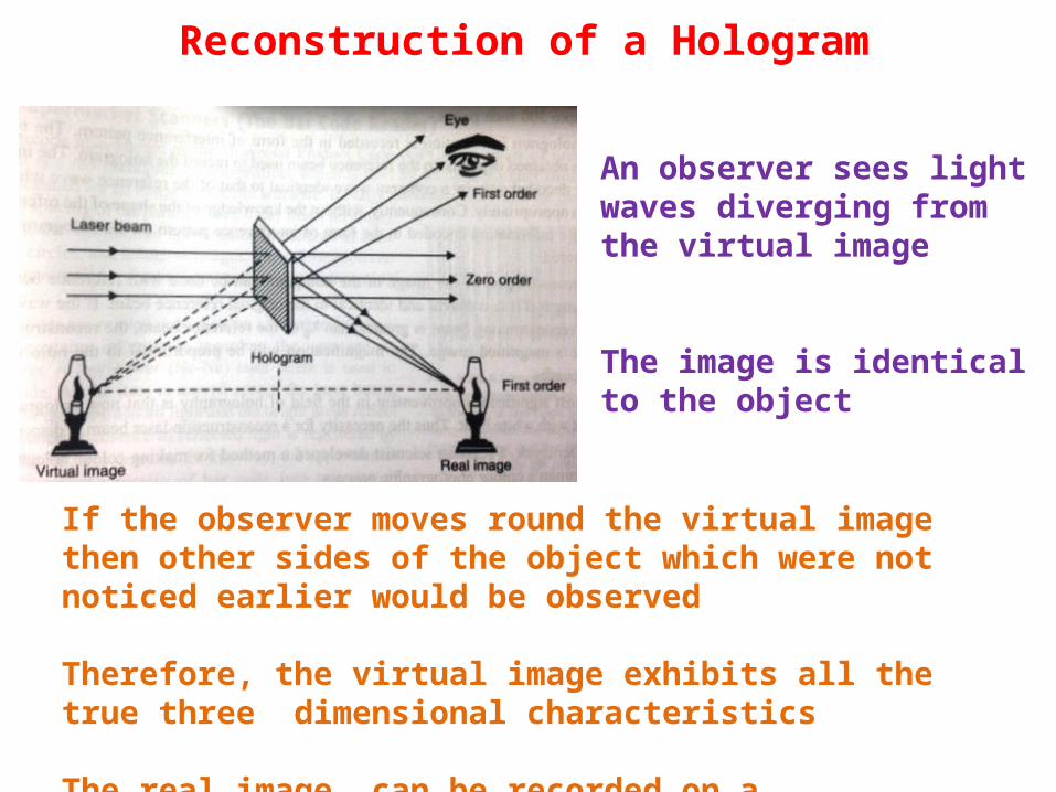
An observer sees light waves diverging from the virtual image
The image is identical to the object
If the observer moves round the virtual image then other sides of the object which were not noticed earlier would be observed
Therefore, the virtual image exhibits all the true three dimensional characteristics
The real image can be recorded on a photographic plate

Applications of Holography
A hologram is a reliable medium for data storage
Several images can be stored on a hologram
The information on a hologram cam be decoded only by a coherent beam identical to that of the reference beam which can be chosen appropriately
Holographic non-destructive technique can be used to discover stresses in a pipe fitting, the stress points on a wheel

Applications of Holography
Holography plays an important role in optical signal processing
Can be used for character recognition and for identification of finger prints
Employed in the production of photographic masks used to produce microelectronic circuits
Holographic interferometry is the standard technique employed to assess the quality of aircraft tyres and
many other high performance aircrafts