sending messages from cc a plc v m · 2019-09-06 · commands, called a “command string” in the...
TRANSCRIPT

In this Chapter...Introduction ...................................................................................................................7-4
ASCII ����������������������������������������������������������������������������������������������������������������������������7-5Modbus ������������������������������������������������������������������������������������������������������������������������7-5Reading the ASCII Reply when using Modbus ��������������������������������������������������������������7-6String Length Limitations with PLC’s ����������������������������������������������������������������������������7-6Sending Strings from multiple PLC’s ��������������������������������������������������������������������������7-11Modbus with Multiple Displays or other Slave Devices� ����������������������������������������������7-12
CLICK PLC by AutomationDirect .................................................................................7-13RS-232 �����������������������������������������������������������������������������������������������������������������������7-13RS-485 �����������������������������������������������������������������������������������������������������������������������7-13ASCII ��������������������������������������������������������������������������������������������������������������������������7-14Modbus ����������������������������������������������������������������������������������������������������������������������7-17Optional Error Checking ���������������������������������������������������������������������������������������������7-21
Productivity3000 PAC by AutomationDirect ..............................................................7-25Ethernet ���������������������������������������������������������������������������������������������������������������������7-25RS-232 �����������������������������������������������������������������������������������������������������������������������7-25RS-485 �����������������������������������������������������������������������������������������������������������������������7-26Embedding the String into PAC memory �������������������������������������������������������������������7-27Sending Strings from Productivity3000 to the ViewMarq display by ASCII over Serial 7-28Sending Strings from Productivity3000 to the ViewMarq display via Modbus ������������7-31Modbus Serial ������������������������������������������������������������������������������������������������������������7-34Optional Error Checking ���������������������������������������������������������������������������������������������7-38Ethernet Modbus TCP ������������������������������������������������������������������������������������������������7-42Optional Error Checking ���������������������������������������������������������������������������������������������7-44
Sending MeSSageS froM a PLC to ViewMarq 5777
ChapterChapterChapter

Do-More PLC by AutomationDirect ...........................................................................7-47RS-232 ����������������������������������������������������������������������������������������������������������������������7-47RS-485 ����������������������������������������������������������������������������������������������������������������������7-47Ethernet ��������������������������������������������������������������������������������������������������������������������7-48ASCII �������������������������������������������������������������������������������������������������������������������������7-48Modbus ���������������������������������������������������������������������������������������������������������������������7-53Modbus TCP �������������������������������������������������������������������������������������������������������������7-63
DirectLogic PLC by AutomationDirect .......................................................................7-66Sending Strings from DirectLogic to the ViewMarq display by ASCII over Serial ��������7-66Using the DirectLogic PRINT instruction ��������������������������������������������������������������������7-67Using PRINTV instruction (D2-260 or D0-06 only) ����������������������������������������������������7-68Embedding the String into PLC memory �������������������������������������������������������������������7-68Sending Strings from DirectLogic to the ViewMarq display by Modbus over Serial ���7-70Optional Error Checking ��������������������������������������������������������������������������������������������7-73Sending Strings from DirectLogic to the ViewMarq display by Modbus over Ethernet ���������������������������������������������������������������������������������������������������������������������������������7-76
PLC Cabling Chart ......................................................................................................7-83
Allen Bradley MicroLogix and SLC PLCs ....................................................................7-84RS-232 ����������������������������������������������������������������������������������������������������������������������7-84ASCII �������������������������������������������������������������������������������������������������������������������������7-85Modbus ���������������������������������������������������������������������������������������������������������������������7-91
Allen Bradley CompactLogix and ControlLogix PLCs ..............................................7-103RS-232 ��������������������������������������������������������������������������������������������������������������������7-103ASCII �����������������������������������������������������������������������������������������������������������������������7-103

User Manual, 1st Ed. Rev. C – MD-USER-M

1
2
3
4
5
6
7
8
9
10
11
12
13
14
A
B
C
D
Chapter 7: Sending Messages From a PLC to ViewMarq
7-4 User Manual, 1st Ed. Rev. F – MD-USER-M
Introduction
As you create a message in the ViewMarq software, the software creates an ASCII string of commands, called a “Command String” in the ViewMarq software. This string may be pasted into your PLC’s instruction or memory, then logic in the PLC will send the message to the ViewMarq.
Click the Copy button to place the command string on to the clipboard. Then paste the string into your PLC instruction.
The ViewMarq LED message display can receive an ASCII Command String by:
Protocol ConnectionASCII RS-232 (Port 1), RS485 (Port 2)
Modbus RTU RS-232 (Port 1), RS485 (Port 2)Modbus TCP Ethernet
Port 2RS485
Port 1RS232
+-SGTXRXRTS
RJ12Port1
RS232
RJ45Ethernet
J45RJernetEthe
+-SGTXRXRXRTS
RJ12RPort1P
RS232R

1
2
3
4
5
6
7
8
9
10
11
12
13
14
A
B
C
D
Chapter 7: Sending Messages From a PLC to ViewMarq
7-5 User Manual, 1st Ed. Rev. F – MD-USER-M
ASCIIWhen the ViewMarq display serial port and the PLC serial port are both set for ASCII, the PLC may send the Command String directly to the display’s port. If the Command String is addressed to a single display, for example <ID 1>, and the display is configured with ASCII Reply turned on, the display will reply with an ASCII string on the same port. If the PLC can receive ASCII strings as well as send them, then you may read the ASCII Reply with the PLC. For more information about ASCII Reply see Chapter 6 – Configuring the ViewMarq LED Display.
RS-232SERIAL
USBPGM
PORT
RUNTERM
STOP
10/100
ETHERNET
H2-DM1E
RRRSS-SSSEER
UUPP
PPOO
TERMTERM
10/100
10/100
ETHERNET
ETHERNET
ETHERNET
H2-DM1E
ASCII
<ID 1><T>Hello World</T>
OK
ASCII
ModbusWhen using the Modbus RTU protocol with the ViewMarq, the same ASCII Command Strings are used but they are embedded within the data portion of the Modbus message (placed into the Modbus registers). The same ASCII Reply is also embedded within the Modbus data section of a message and can be read from a separate set of Modbus registers.
Command Strings are written to the ViewMarq Command String buffer starting at Modbus Registers 411000 (up to 256 words).
ASCII Replies are read from the ViewMarq Status Buffer starting at Modbus Registers 411500 (up to 256 words).
NOTE: The carriage return termination (0x0d) is required in the Command String that is sent from the PLC.
NOTE: The carriage return termination (0x0d) is still required in the Command String that is embedded with the Modbus message.
Attention!: Command Strings should be sent at least 100 ms apart.ATTENTION

1
2
3
4
5
6
7
8
9
10
11
12
13
14
A
B
C
D
Chapter 7: Sending Messages From a PLC to ViewMarq
7-6 User Manual, 1st Ed. Rev. F – MD-USER-M
Reading the ASCII Reply when using ModbusTo accurately read the ASCII reply from the ViewMarq display, follow the steps below:
1) Write the Command String to the display Modbus register block starting at 411000
2) Monitor the value in the first Modbus register 411000
3) When the value in register changes to 0 (zero), this indicates the message has been processed and the ASCII Reply buffer has been updated.
4) Read the updated ASCII Reply from the register block starting at 411500
RS-232SERIAL
USBPGM
PORT
RUNTERM
STOP
10/100
ETHERNET
H2-DM1E
RRRSS-SSSEER
UUPP
PPOO
TERMTERM
10/100
10/100
ETHERNET
ETHERNET
ETHERNET
H2-DM1E
ASCIIWrite: <ID 1><T>Hello World</T> to 41100
Read: OK from 411500
Read: 0 from 411000
ASCII
String Length Limitations with PLC’sDepending on the PLC, instruction and protocol you may not be able to send an ASCII command string that is 500 characters long in one PLC ASCII or Modbus instruction. For example, the AutomationDirect PLC’s have the following limitations.
PLC Instruction Protocol Maximum Characters
CLICK Send ASCII 128CLICK Send Modbus 246P3000 ASCII Out ASCII 128P3000 MWX - String Modbus 128P3000 MWX - Integers Modbus 240
Do-more STREAMOUT ASCII 1023Do-more MWX Modbus 246
DirectLogic PRINT ASCII 128
DirectLogic VPRINT ASCII 128DirectLogic MWX Modbus 250
In order to send a String greater than the limit of the PLC instruction, the string will need to be sent in multiple parts. The ViewMarq Display is looking for an <ID n> and a Termination Character $0D (Carriage Return) before it processes its buffer. Therefore a long command string may be sent like this:
PLC Instruction 1 <ID n> Command String Part 1
PLC Instruction 2 Command String Part 2 $0D

1
2
3
4
5
6
7
8
9
10
11
12
13
14
A
B
C
D
Chapter 7: Sending Messages From a PLC to ViewMarq
7-7 User Manual, 1st Ed. Rev. F – MD-USER-M
Sending a Command String in Multiple Parts using a CLICK PLC
CLICK ASCII Send Example
For example, the following Command String is 181 characters and is too long for a CLICK ASCII Send Instruction.
<ID 0><CLR>><WIN 0 0 287 31><POS 0 0><CJ><BL N><CS 0><GRN> <T>AutomationDirect</T><POS 0 8><CJ><RED><T>#1 in</T><POS 0 16><CJ><T>Service</T><POS 0 24><CJ><AMB><T>12 Years in a row</T>It needs to be sent in two parts:
Command String Part 1
<ID 0><CLR><WIN 0 0 287 31><POS 0 0><CJ><BL N><CS 0><GRN> <T>AutomationDirect</T>
Command String Part 2
<POS 0 8><CJ><RED><T>#1 in</T><POS 0 16><CJ><T>Service</T> <POS 0 24><CJ><AMB><T>12 Years in a row</T>It does not matter where the Command String is broken apart because it will not be processed by the ViewMarq Display until the Termination Character at the end of the Command String is received.
Command String Part 1 Command String Part 2

1
2
3
4
5
6
7
8
9
10
11
12
13
14
A
B
C
D
Chapter 7: Sending Messages From a PLC to ViewMarq
7-8 User Manual, 1st Ed. Rev. F – MD-USER-M
CLICK Modbus Send Example
When using Modbus, ASCII strings must be an even number of bytes in length because Modbus registers are 16 bits (2 bytes) long.
Since the Modbus Write instructions are limited depending on the PLC, longer ASCII strings must be sent by using successive Modbus Write instructions. This example uses the CLICK PLC which limits the Modbus Write to 246 characters.
For example, the ASCII string below is 274 characters long including the Termination Character ($0D).
<ID 0><CLR><WIN 0 0 287 31><POS 0 0><CJ><BL N><CS 9><GRN><T>A</T> <CS 3><AMB><T>utomation</T><CS 5><GRN><T>D</T><CS 3><AMB><T> irect</T><POS 0 16><CJ><CS 0><GRN><T> #1 in Service</T><POS 0 24><RJ><AMB><T>12 </T><RED><T>Years</T><GRN><T> in</T><AMB><T> a </T><RED><T>row</T>To send it to the ViewMarq using a Modbus Write, the ASCII string will need to be sent in two parts. The first is sent without a Termination Character to Modbus address 411000.

1
2
3
4
5
6
7
8
9
10
11
12
13
14
A
B
C
D
Chapter 7: Sending Messages From a PLC to ViewMarq
7-9 User Manual, 1st Ed. Rev. F – MD-USER-M
Command String Part 1 - 228 Characters
<ID 0><CLR><WIN 0 0 287 31><POS 0 0><CJ><BL N><CS 9><GRN><T>A</T> <CS 3><AMB><T>utomation</T><CS 5><GRN><T>D</T><CS 3><AMB><T>irect </T><POS 0 16><CJ><CS 0><GRN><T> #1 in Service</T><POS 0 24> <RJ><AMB><T>12 </T><RED><T>Years</T>
The second is sent with a Termination Character ($0D) to Modbus address 411114 = [411000 + 228 characters / 2 characters per byte)].
Command String Part 2 - 44 characters + termination character ($0D) = 45 characters
<GRN><T> in</T> <AMB><T> a </T><RED><T>row</T>Notice the Termination Character is only added to the last string. This increases the length to 45 characters. As you will see, because this length is an odd number of characters, it makes it necessary to add one to the length to keep the number even in the Modbus Write instruction. It is not shown in the string above, because it is not added by ViewMarq, but added in the PLC instruction
Dividing up the Command String
Each Command string may be broken at any location that creates an even length string. Consecutive strings must be sent to the very next Modbus register after the previous string. The last string may be even or odd because the length in the Modbus Write instruction can be rounded up. This extra character is allowed in the last command string because ViewMarq will only process the string up to the Termination Character (Carriage Return). Any characters following this will be ignored
If the strings are NOT written to the correct address, then they may:1) Overlap causing a syntax error
2) Leave gaps between the parts of the ASCII string that contain unexpected characters or NULL’s.
Unexpected characters may cause a syntax error. If a NULL is encountered by the ViewMarq, it will stop processing the string at the NULL and wait until the NULL is replaced

1
2
3
4
5
6
7
8
9
10
11
12
13
14
A
B
C
D
Chapter 7: Sending Messages From a PLC to ViewMarq
7-10 User Manual, 1st Ed. Rev. F – MD-USER-M
In the example below, the Command String has already been copied into the CLICK memory location TXT1 – TXT272 and the Termination Character ($0D) has been copied into TXT273. (See the following Section “CLICK PLC by AutomationDirect – Modbus” for details about copying the Command String into memory.)
Command String Part 1 Command String Part 2

1
2
3
4
5
6
7
8
9
10
11
12
13
14
A
B
C
D
Chapter 7: Sending Messages From a PLC to ViewMarq
7-11 User Manual, 1st Ed. Rev. F – MD-USER-M
Sending Strings from multiple PLC’sThe ViewMarq Message LED message display is a slave device. If more than one PLC, master in this case, is sending strings to the display, the PLC logic must be written in such a way as to prevent the two master PLC’s from interfering with each other.
Care must be taken so that one PLC has completed sending its command string before another PLC sends a command string. Once a complete command string (<ID n> and $0D) has been received by the LED Display, time must be given to process it. A delay between complete command strings of 100ms is required
RS-232SERIAL
USBPGM
PORT
RUNTERM
STOP
10/100
ETHERNET
H2-DM1E
RRRSS--SSSEERR
UUPPP
PPOO
TERTERM
10/100
10/100
ETHERNET
ETHERNET
ETHERNET
H2-DM1E
PLC #1
RS-232SERIAL
USBPGM
PORT
RUNTERM
STOP
10/100
ETHERNET
H2-DM1E
RRRSS--SSSEERR
UUPPP
PPOO
TERTERM
10/100
10/100
ETHERNET
ETHERNET
ETHERNET
H2-DM1E
PLC #2
<ID 1><T>Hello World</T> ASCII
<ID 1>
<T>Aut
omatio
nDirec
t</T>
100ms delay betweenCommand Strings

1
2
3
4
5
6
7
8
9
10
11
12
13
14
A
B
C
D
Chapter 7: Sending Messages From a PLC to ViewMarq
7-12 User Manual, 1st Ed. Rev. F – MD-USER-M
Modbus with Multiple Displays or other Slave Devices.The ViewMarq is a Standard Modbus Slave. On a multi-drop Modbus RTU network there may be multiple Modbus slave devices including one or more ViewMarq displays. If Modbus requests are being made of alternating slave devices, the ViewMarq displays require a 55ms delay between these packets. If the ViewMarq Display is polled during this time it will not respond and a timeout error will occur in the Master device.
Whenever possible, the poll rate of the master device should be set to 55ms or longer to create this delay between packets. As an example, this can be accomplished with the AutomationDirect Productivity3000 PAC by setting the “Response / Request Delay” to 55ms or higher for the RS-485 port.
For masters devices without a port delay setting the user will need to create delays between communication instructions in their PLC code.
RS-232SERIAL
USBPGM
PORT
RUNTERM
STOP
10/100
ETHERNET
H2-DM1E
RRRSS--SSSEERR
UUPPP
PPOO
TERMTERM
10/100
10/100
ETHERNET
ETHERNET
ETHERNET
H2-DM1E
Display 2Display 1 Display 2
<ID 1><T>Hello World</T> <ID 2><T>Hello World</T>
55ms delay
Display 1
<ID 1><T>Hello World</T><ID 1
1
2
3
4
5
6
7
8
9
10
11
12
13
14
A
B
C
D
Chapter 7: Sending Messages From a PLC to ViewMarq
7-13 User Manual, 1st Ed. Rev. F – MD-USER-M
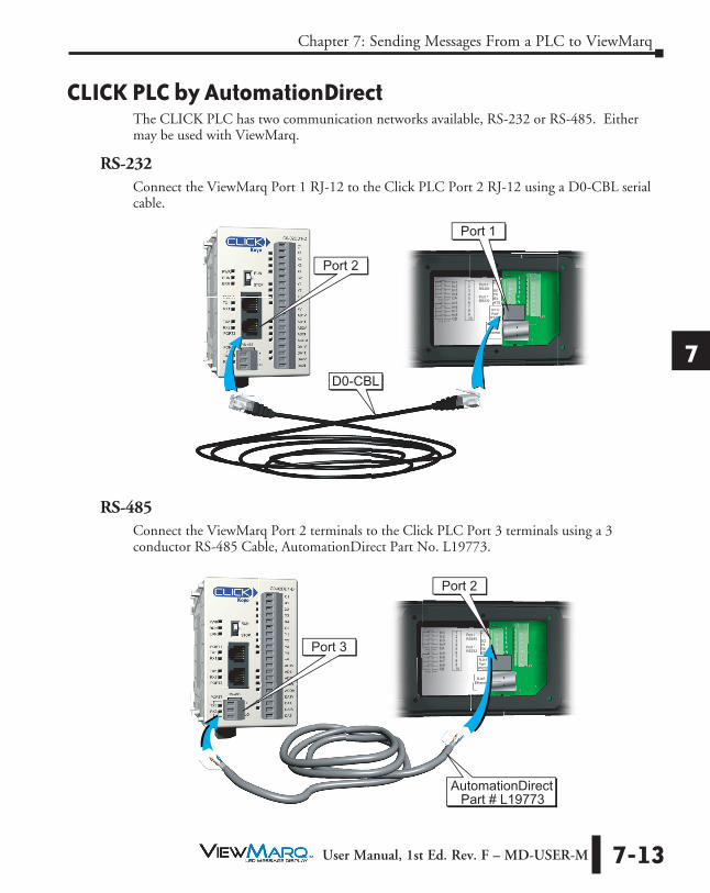
CLICK PLC by AutomationDirectThe CLICK PLC has two communication networks available, RS-232 or RS-485. Either may be used with ViewMarq.
RS-232Connect the ViewMarq Port 1 RJ-12 to the Click PLC Port 2 RJ-12 using a D0-CBL serial cable.
12345678910
In 1In 2In 3In 4CAIn 5In 6In 7In 8CB
Port 2RS485
Port 1RS232
+-SGTXRXRTS
RJ12Port1
RS232
RJ45Ethernet
S23SS23
RJ45thernet
285
132
+-SGTXRX32 RTS32 RTSRTS
RJ12Port1
RS232
D0-CBL
Port 1
Port 2
RS-485Connect the ViewMarq Port 2 terminals to the Click PLC Port 3 terminals using a 3 conductor RS-485 Cable, AutomationDirect Part No. L19773.
12345678910
In 1In 2In 3In 4CAIn 5In 6In 7In 8CB
Port 2RS485
Port 1RS232
+-SGTXRXRTS
RJ12Port1
RS232
RJ45Ethernet
S23SS23
RJ45Eth t
285
132
+-SGTXRX32 RTS32 RTSRTS
RJ12Port1
RS232
Ethernet
Port 3
Port 2
Part # L19773AutomationDirect

1
2
3
4
5
6
7
8
9
10
11
12
13
14
A
B
C
D
Chapter 7: Sending Messages From a PLC to ViewMarq
7-14 User Manual, 1st Ed. Rev. F – MD-USER-M
The Click PLC Send instruction may utilize ASCII or Modbus depending on how the port is configured. Both methods are shown.
ASCII1) Using the CLICK Programming Software configure the CLICK Port 2 or Port 3 for
ASCII protocol.
2) Set the port on the CLICK PLC Com Port to match the settings for the ViewMarq display.
3) In the ViewMarq Software, type and configure a message. Copy the string in the Command String window by selecting Copy on the Command String Toolbar.
Take note of <ID 0> in the string above. This identifies which ViewMarq LED display is intended to display the message on a multiple displayl network such as RS485. Refer to Other Tools, LED Display ID in Chapter 5. The default ID for all ViewMarq LED message displays is 1 and is set using the LED Display Configuration Dialog which is covered in Chapter 6.

1
2
3
4
5
6
7
8
9
10
11
12
13
14
A
B
C
D
Chapter 7: Sending Messages From a PLC to ViewMarq
7-15 User Manual, 1st Ed. Rev. F – MD-USER-M
4) In the CLICK Programming software use a SEND instruction as shown below.
a) Select Port 2 for RS232 (or 3 for RS 485) for the Com Port.
b) Select the Static Text Message radio button
c) Click in the Text Box and press Ctrl-V on your keyboard to paste the String into the instruction.
d) Add quotes to the beginning and end of the string.
e) Select the Termination Code checkbox
f) Select 1 Character radio button
g) Enter $0D or $0A to embed a Carriage Return at the end of the string.
h) Select an address for the success bit. For example C1.
i) Select OK

1
2
3
4
5
6
7
8
9
10
11
12
13
14
A
B
C
D
Chapter 7: Sending Messages From a PLC to ViewMarq
7-16 User Manual, 1st Ed. Rev. F – MD-USER-M
Example CLICK PLC code for sending ASCII string.
NOTE: To prevent the string from being sent with every scan of the PLC use an EDGE triggered (or One Shot) instruction.
Attention!: Command Strings should be sent at least 100 ms apart.ATTENTION

1
2
3
4
5
6
7
8
9
10
11
12
13
14
A
B
C
D
Chapter 7: Sending Messages From a PLC to ViewMarq
7-17 User Manual, 1st Ed. Rev. F – MD-USER-M
Modbus1) Using the CLICK Programming Software set the Port on the CLICK PLC Com Port to
Modbus.
2) Set the port on the CLICK PLC Com Port to match the settings for the ViewMarq display.
3) In the ViewMarq Software, type and configure a message. Copy the string in the Command String window by selecting Copy on the Command String Toolbar.
Take note of <ID 0> in the string above. This identifies which ViewMarq LED display is intended to display the message on a multiple display network such as RS485. Refer to Other Tools, LED Display ID in Chapter 5. The default ID for all ViewMarq LED message displays is 1 and is set using the LED Display Configuration dialog which is covered in Chapter 6.

1
2
3
4
5
6
7
8
9
10
11
12
13
14
A
B
C
D
Chapter 7: Sending Messages From a PLC to ViewMarq
7-18 User Manual, 1st Ed. Rev. F – MD-USER-M
4) Paste the string into a Copy command as shown.
NOTE: Quotation marks must be placed at the beginning and end of the String that was pasted into the “Source” field of this instruction. Enter in the beginning TXT address of the block where the String will reside. Note the ending address of the destination. This will be used in the next command.
5) Add a carriage return to the end of the string using another Copy command.
The carriage return character (entered as $0D in the Source field), should be placed into the next TXT address after the end of the block used in the previous COPY command. In this example, the end TXT address from the block used in the previous COPY command was TXT75, so TXT76 is used in this COPY command Destination address.

1
2
3
4
5
6
7
8
9
10
11
12
13
14
A
B
C
D
Chapter 7: Sending Messages From a PLC to ViewMarq
7-19 User Manual, 1st Ed. Rev. F – MD-USER-M
6) In the CLICK Programming software use a SEND instruction as shown below.
a) Select Port 2 for RS232 (or 3 for RS 485) for the Com Port.
b) Select the Slave ID (Node Address) for the connected ViewMarq.
c) The Command String is written to ViewMarq Command String Buffer starting at Modbus address 411000.
d) The number of Master Addresses may be set to the maximum possible value for the instruction.
e) Configure any Status Flags desired for the program control.
f) Select OK
NOTE: To prevent the string from being sent with every scan of the PLC use an EDGE triggered (or One Shot) instruction.

1
2
3
4
5
6
7
8
9
10
11
12
13
14
A
B
C
D
Chapter 7: Sending Messages From a PLC to ViewMarq
7-20 User Manual, 1st Ed. Rev. F – MD-USER-M
Example CLICK PLC code for sending ASCII string over Modbus.

1
2
3
4
5
6
7
8
9
10
11
12
13
14
A
B
C
D
Chapter 7: Sending Messages From a PLC to ViewMarq
7-21 User Manual, 1st Ed. Rev. F – MD-USER-M
Optional Error CheckingYou may choose to read the ViewMarq status to make sure the ASCII string was received with no errors.
1) In the Click Programming software, use a Receive instruction as shown below to read the Command Block address until it equals 0. This indicates that the ViewMarq display has finished processing the command and the status is ready to be read.
a) Select Port 2 for RS232 (or 3 for RS 485) for the Com Port that you previous set to Modbus.
b) Select the Slave ID (Node Address) for the connected ViewMarq.
c) Read the first address of the Command String Buffer, Modbus address 411000.
d) Choose a Master Address that is an unused, Integer address (such as the DS data type) that can be compared to 0. Once this register is equal to 0, the Status Block can be read.
e) Configure any Status Flags desired for program control.
f) Select OK

1
2
3
4
5
6
7
8
9
10
11
12
13
14
A
B
C
D
Chapter 7: Sending Messages From a PLC to ViewMarq
7-22 User Manual, 1st Ed. Rev. F – MD-USER-M
2) Once the Command Block is equal to 0, use a Recieve instruction to read the Status Block to verify that the Command String written was accepted by the ViewMarq display.
a) Select Port 2 for RS232 (or 3 for RS 485) for the Com Port that you previous set to Modbus.
b) Select the Slave ID (Node Address) for the connected ViewMarq.
c) The Status String can be read from the ViewMarq display starting at Modbus address 411500.
d) Choose an unused, available block of 128 TXT addresses.
e) Configure any Status Flags desired for program control.
f) Select OK

1
2
3
4
5
6
7
8
9
10
11
12
13
14
A
B
C
D
Chapter 7: Sending Messages From a PLC to ViewMarq
7-23 User Manual, 1st Ed. Rev. F – MD-USER-M
3) Once the string in the Status Block has been read, check the value of the string for the text “OK” using the Search instruction.
a) Enter search text “OK”
b) Enter the starting and ending addresses of the block of TXT addresses in the previous Receive instruction.
c) Choose an available Integer address for the Result.
d) Choose an available C address for the Result Flag.
e) Select OK.

1
2
3
4
5
6
7
8
9
10
11
12
13
14
A
B
C
D
Chapter 7: Sending Messages From a PLC to ViewMarq
7-24 User Manual, 1st Ed. Rev. F – MD-USER-M
Example CLICK PLC code for checking the Viewmarq Status Block.

1
2
3
4
5
6
7
8
9
10
11
12
13
14
A
B
C
D
Chapter 7: Sending Messages From a PLC to ViewMarq
7-25 User Manual, 1st Ed. Rev. F – MD-USER-M
Productivity3000 PAC by AutomationDirectThe Productivity3000 PAC has three communication networks available, Ethernet, RS-232 or RS-485. Either of the three may be used with ViewMarq.
EthernetConnect the ViewMarq RJ-45 Ethernet port to the Productivity3000 RJ-45 Ethernet port using a Cat5e Ethernet crossover cable.
Cat5e Crossover Cable
12345678910
In 1In 2In 3In 4CAIn 5In 6In 7In 8CB
Port 2RS485
Port 1RS232
+-SGTXRXRTS
RJ12Port1
RS232
RJ45Ethernet
S23SS23
RJ45Ethernet
285
132
+-SGTXRX32 RTS32 RTSRTS
RJ12Port1
RS232
Productivity3000P3-550 CPU
ViewMarq LEDMessage Display
RS-232Connect the ViewMarq RJ-12 Port 1 to the Productivity3000 RJ-12 RS-232 port using a D0-CBL serial cable.
12345678910
In 1In 2In 3In 4CAIn 5In 6In 7In 8CB
Port 2RS485
Port 1RS232
+-SGTXRXRTS
RJ12Port1
RS232
RJ45Ethernet
S23SS23
RJ45Ethernet
285
132
+-SGTXRX32 RTS32 RTSRTS
RJ12Port1
RS232
RS232 CablePart # D0-CBL
Port 1
Productivity3000P3-550 CPU
ViewMarq LEDMessage Display

1
2
3
4
5
6
7
8
9
10
11
12
13
14
A
B
C
D
Chapter 7: Sending Messages From a PLC to ViewMarq
7-26 User Manual, 1st Ed. Rev. F – MD-USER-M
RS-485Connect the ViewMarq Port 2 terminals to the Productivity3000 RS-485 terminals using a 3 conductor RS-485 Cable, AutomationDirect Part No. L19773.
12345678910
In 1In 2In 3In 4CAIn 5In 6In 7In 8CB
Port 2RS485
Port 1RS232
+-SGTXRXRTS
RJ12Port1
RS232
RJ45Ethernet
S23SS23
RJ45Ethernet
285
132
+-SGTXRX32 RTS32 RTSRTS
RJ12Port1
RS232
RS485 CableAutomationDirect
Part # L19773
Port 2
ViewMarq LEDMessage Display
Productivity3000P3-550 CPU
The Productivity3000 PAC may communicate with the ViewMarq LED display by ASCII, Modbus RTU or Modbus TCP.
This section discusses:• Sending a Command String by ASCII over Serial • Sending a Command String by Modbus over Serial • Sending a Command String by Modbus TCP over Ethernet

1
2
3
4
5
6
7
8
9
10
11
12
13
14
A
B
C
D
Chapter 7: Sending Messages From a PLC to ViewMarq
7-27 User Manual, 1st Ed. Rev. F – MD-USER-M
Embedding the String into PAC memory1) In the ViewMarq software, type and configure a message. Copy the string in the
Command String window by selecting Copy on the Command String Toolbar.
2) In the Productivity Suite Programming Software Paste (Ctrl-V) the Command String into the Copy Data (CPD) Instruction as shown.
NOTE: Quotation marks must be placed around the message that has been pasted into the CPD instruction. ViewMarq_SW_String must be a String Data type in the Productivity3000 PAC.

1
2
3
4
5
6
7
8
9
10
11
12
13
14
A
B
C
D
Chapter 7: Sending Messages From a PLC to ViewMarq
7-28 User Manual, 1st Ed. Rev. F – MD-USER-M
Sending Strings from Productivity3000 to the ViewMarq display by ASCII over Serial
The PAC port must be configured for “ASCII / Custom Protocol” in order to allow ASCII strings to be sent.
1) Go to Setup>Hardware Configuration and double click on the P3-550 box in the Center window:

1
2
3
4
5
6
7
8
9
10
11
12
13
14
A
B
C
D
Chapter 7: Sending Messages From a PLC to ViewMarq
7-29 User Manual, 1st Ed. Rev. F – MD-USER-M
2) Click the Serial Ports tab.
3) Match the Baud Rate, Data Bits and Stop Bits to the serial port settings of the ViewMarq display serial port.
4) Choose ASCII / Custom Protocol on the Protocol selection.

1
2
3
4
5
6
7
8
9
10
11
12
13
14
A
B
C
D
Chapter 7: Sending Messages From a PLC to ViewMarq
7-30 User Manual, 1st Ed. Rev. F – MD-USER-M
5) Now that the port has been configured correctly, use the AOUT (ASCII Out) instruction as shown below to choose the String tag created previously, and to send out the serial port.
Remember to add the one character termination code for a carriage return, 0x0d.
NOTE: The AOUT instruction is Edge-triggered so the String will be sent only once when the enable leg goes from low to high.
The “ASCII Reply” option in the ViewMarq should be disabled when sending ASCII strings with the AOUT instruction in Productivity3000. See Chapter 6 - Configuring the ViewMarq LED Display for more information. If the application requires more reliable error detection and handshaking consider using Modbus communications instead.
Example P3000 code for sending an ASCII string out the serial port.
Attention!: Command Strings should be sent at least 100 ms apart.ATTENTION

1
2
3
4
5
6
7
8
9
10
11
12
13
14
A
B
C
D
Chapter 7: Sending Messages From a PLC to ViewMarq
7-31 User Manual, 1st Ed. Rev. F – MD-USER-M
Sending Strings from Productivity3000 to the ViewMarq display via ModbusTo send a string by Modbus, a couple of steps need to be taken.
1) String length must be calculated.
2) Termination Codes must be added to the end of the string.
Calculating String Length
Add a String Length (SLEN) Instruction to move the length of the string into a Signed Integer 32 tag to be used later.
Adding Termination Codes
You will need to add a termination character (“$0d”) to the end of the message string. In Productivity3000, non-printable characters cannot be directly inserted into a string tag. Here are the steps to insert the characters at the end of the string:
1) Create an Unsigned Int 8 array and use a CPD instruction copy 0x0D to this array.

1
2
3
4
5
6
7
8
9
10
11
12
13
14
A
B
C
D
Chapter 7: Sending Messages From a PLC to ViewMarq
7-32 User Manual, 1st Ed. Rev. F – MD-USER-M
2) Use the CPC (Copy Character) instruction to create a string of 1 character to move 1 byte into.
3) Combine the two strings together into a string ready to send out the port using the PKS (Pack String) instruction.
4) Finally, set the destination tag string length to 128.

1
2
3
4
5
6
7
8
9
10
11
12
13
14
A
B
C
D
Chapter 7: Sending Messages From a PLC to ViewMarq
7-33 User Manual, 1st Ed. Rev. F – MD-USER-M
Example P3000 code for sending an ASCII string out the serial port.

1
2
3
4
5
6
7
8
9
10
11
12
13
14
A
B
C
D
Chapter 7: Sending Messages From a PLC to ViewMarq
7-34 User Manual, 1st Ed. Rev. F – MD-USER-M
Modbus Serial
The PAC port must be configured for “Modbus RTU” in order to allow raw ASCII strings encapsulated within a Modbus serial packet to be sent.
1) Go to Setup > Hardware Configuration and double click on the P3-550 box in the Center window
NOTE: See previous section for details about preparing the string to send via Modbus.

1
2
3
4
5
6
7
8
9
10
11
12
13
14
A
B
C
D
Chapter 7: Sending Messages From a PLC to ViewMarq
7-35 User Manual, 1st Ed. Rev. F – MD-USER-M
2) Click the Serial Ports tab.
3) Match the Baud rate, Parity, Data bits and Stop bits to the serial port settings of the ViewMarq display serial port.
4) Choose Modbus RTU on the Protocol selection.

1
2
3
4
5
6
7
8
9
10
11
12
13
14
A
B
C
D
Chapter 7: Sending Messages From a PLC to ViewMarq
7-36 User Manual, 1st Ed. Rev. F – MD-USER-M
Now that the port has been configured correctly, use a Modbus Write (MWX) Instruction to write the data over as shown.
1) Choose the Serial Port option and select which CPU the message will be sent from.
a) The Slave Node Number should match the node in the LED Display Configuration.
b) Word Swap and Byte Swap should be checked assuming the selections are Off in the ViewMarq display.
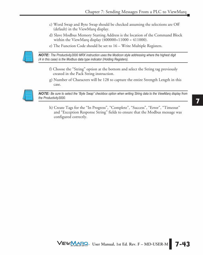
c) Slave Modbus Memory Starting Address is the location of the Command Block within the ViewMarq display (400000+11000 = 411000).
d) The Function Code should be set to 16 – Write Multiple Registers.

1
2
3
4
5
6
7
8
9
10
11
12
13
14
A
B
C
D
Chapter 7: Sending Messages From a PLC to ViewMarq
7-37 User Manual, 1st Ed. Rev. F – MD-USER-M
NOTE: The Productivity3000 MWX instruction uses the Modicon style addressing where the highest digit (4 in this case) is the Modbus data type indicator (Holding Registers).
e) Choose the “String” option at the bottom and select the String tag previously created in the Pack String Instruction.
f) The Number of Characters should be set at least as high as the Character Count in the ViewMarq Software Command String Viewer.
In this example, 77 would be sufficient, but using the maximum of 128 will also work correctly. ViewMarq ignores any data after the 0D.
g) Create Tags for the “In Progress”, “Complete”, “Success”, “Error”, “Timeout” and “Exception Response String” fields to ensure that the Modbus message was configured correctly.

1
2
3
4
5
6
7
8
9
10
11
12
13
14
A
B
C
D
Chapter 7: Sending Messages From a PLC to ViewMarq
7-38 User Manual, 1st Ed. Rev. F – MD-USER-M
Optional Error CheckingAfter the Modbus Write is successful, the ViewMarq display will process the message. When the display has finished processing the message it will clear the Command Block (411000).
1) The next step of the logic should be to read the first element of Command Block using a Modbus Read (MRX) Instruction until it reads 0.
a) Slave Modbus Starting Address is the location of the Command Block within the ViewMarq display (400000+11000 = 411000).
b) The Function Code should be set to 3 – Read Holding Registers.
NOTE: The Productivity3000 MRX instruction uses the Modicon style addressing where the highest digit (4 in this case) is the Modbus data type indicator (Holding Registers).
c) Choose the “Non-array” option at the bottom and create an Unsigned Integer 16 tag to read the first register of the Command Block into.

1
2
3
4
5
6
7
8
9
10
11
12
13
14
A
B
C
D
Chapter 7: Sending Messages From a PLC to ViewMarq
7-39 User Manual, 1st Ed. Rev. F – MD-USER-M
d) Keep executing this MRX command until the first register of the Command Block reads 0.
2) After the first register of the Command Block returns a 0, the Reply Status Block should be read using another MRX instruction.
a) Slave Modbus Starting Address is the location of the Reply Status Block within the ViewMarq display. (400000+11500 = 411500).
b) Word Swap and Byte Swap should be checked assuming the selections are Off (default) in the ViewMarq display.
c) The Function Code should be set to 3 – Read Holding Registers.
NOTE: The Productivity3000 MRX instruction uses the Modicon style addressing where the highest digit (4 in this case) is the Modbus data type indicator (Holding Registers).

1
2
3
4
5
6
7
8
9
10
11
12
13
14
A
B
C
D
Chapter 7: Sending Messages From a PLC to ViewMarq
7-40 User Manual, 1st Ed. Rev. F – MD-USER-M
d) Choose the “String” option at the bottom and create a String tag to read the Status info into. Choose 128 characters as the length.
3) Once the string in the Reply Status Block has been read, check the value of the string for the text “OK” using the Find instruction.
a) Select the Source String where the Status Reply was stored
b) Enter a Found Index Tag, this tag is required, but not important in this case
c) Enter the search Range from 0 to 128
d) Enter a Tag for the Success bit. This tag will be on if “OK” is found
e) Enter search text “OK”
f) Select OK

1
2
3
4
5
6
7
8
9
10
11
12
13
14
A
B
C
D
Chapter 7: Sending Messages From a PLC to ViewMarq
7-41 User Manual, 1st Ed. Rev. F – MD-USER-M
Example P3000 Code for writing an ASCII string to ViewMarq over Modbus Serial

1
2
3
4
5
6
7
8
9
10
11
12
13
14
A
B
C
D
Chapter 7: Sending Messages From a PLC to ViewMarq
7-42 User Manual, 1st Ed. Rev. F – MD-USER-M
Ethernet Modbus TCPSending messages from the Productivity3000 to the ViewMarq display via Modbus TCP is the same as sending messages over Modbus RTU with one change to the MRX and MWX instructions.
Instead of choosing the “Serial Port” option in the MWX and MRX instructions, choose the “Ethernet Port” option and enter in the IP address of the ViewMarq display. Leave the TCP Port Number as 502 and the Slave Node Number as 255.
1) With the Ethernet port properly configured in the Productivity3000 PAC, use a Modbus Write (MWX) Instruction to write the data over as shown.
a) Enter in the IP address of the ViewMarq display.
b) Leave the TCP Port Number as 502 and the Slave Node Number as 255.
1
2
3
4
5
6
7
8
9
10
11
12
13
14
A
B
C
D
Chapter 7: Sending Messages From a PLC to ViewMarq
7-43 User Manual, 1st Ed. Rev. F – MD-USER-M
c) Word Swap and Byte Swap should be checked assuming the selections are Off (default) in the ViewMarq display.
d) Slave Modbus Memory Starting Address is the location of the Command Block within the ViewMarq display (400000+11000 = 411000).
e) The Function Code should be set to 16 – Write Multiple Registers.
NOTE: The Productivity3000 MRX instruction uses the Modicon style addressing where the highest digit (4 in this case) is the Modbus data type indicator (Holding Registers).
f) Choose the “String” option at the bottom and select the String tag previously created in the Pack String instruction.
g) Number of Characters will be 128 to capture the entire Strength Length in this case.
NOTE: Be sure to select the “Byte Swap” checkbox option when writing String data to the ViewMarq display from the Productivity3000.
h) Create Tags for the “In Progress”, “Complete”, “Success”, “Error”, “Timeout” and “Exception Response String” fields to ensure that the Modbus message was configured correctly.

1
2
3
4
5
6
7
8
9
10
11
12
13
14
A
B
C
D
Chapter 7: Sending Messages From a PLC to ViewMarq
7-44 User Manual, 1st Ed. Rev. F – MD-USER-M
Optional Error CheckingAfter the Modbus Write is successful, the ViewMarq display will process the message. When the display has finished processing the Message it will clear the Command Block (411000).
1) The next step of the logic should be to read the first element of Command Block using a Modbus Read (MRX) Instruction until it reads 0.
a) Slave Modbus Starting Address is the location of the Command Block within the ViewMarq display (400000+11000 = 411000).
b) The Function Code should be set to 3 – Read Holding Registers.
NOTE: The Productivity3000 MRX instruction uses the Modicon style addressing where the highest digit (4 in this case) is the Modbus data type indicator (Holding Registers).
c) Choose the “Non-array” option at the bottom and create an Unsigned Integer 16 tag to read the first register of the Command Block into.
d) Keep executing this MRX command until the first register of the Command Block reads 0.

1
2
3
4
5
6
7
8
9
10
11
12
13
14
A
B
C
D
Chapter 7: Sending Messages From a PLC to ViewMarq
7-45 User Manual, 1st Ed. Rev. F – MD-USER-M
2) After the first register of the Command Block returns a 0, the Reply Status Block should be read using another MRX instruction.
a) Slave Modbus Starting Address is the location of the Command Block within the ViewMarq display (400000+11500 = 411500).
b) Word Swap and Byte Swap should be checked assuming the selections are Off in the ViewMarq display.
c) The Function Code should be set to 3 – Read Holding Registers.
NOTE: The Productivity3000 MRX instruction uses the Modicon style addressing where the highest digit (4 in this case) is the Modbus data type indicator (Holding Registers).
d) Choose the “String” option at the bottom and create a String tag to read the Status info into. Choose 128 characters as the length.

1
2
3
4
5
6
7
8
9
10
11
12
13
14
A
B
C
D
Chapter 7: Sending Messages From a PLC to ViewMarq
7-46 User Manual, 1st Ed. Rev. F – MD-USER-M
Example P3000 code for writing an ASCII string to ViewMarq over Modbus Ethernet.

1
2
3
4
5
6
7
8
9
10
11
12
13
14
A
B
C
D
Chapter 7: Sending Messages From a PLC to ViewMarq
7-47 User Manual, 1st Ed. Rev. F – MD-USER-M
Do-More PLC by AutomationDirectThe Do-More PLC has three communication networks available; RS-232, RS-485 and Ethernet. Any of the three may be used with the ViewMarq LED display.
RS-232Connect the ViewMarq RJ-12 Port 1 to the Do-more H2-DM1E CPU RJ-12 port or H2-SERIO-4 RJ-12 port using a D0-CBL serial cable.
12345678910
In 1In 2In 3In 4CAIn 5In 6In 7In 8CB
Port 2RS485
Port 1RS232
+-SGTXRXRTS
RJ12Port1
RS232
RJ45Ethernet
S23SS23
RJ45Ethernet
285
132
+-SGTXRX32 RTS32 RTSRTS
RJ12Port1
RS232
RS232 CablePart # D0-CBL
Port 1
Do-moreH2-DM1E
Do-moreH2-SERIO-4
ViewMarq LEDMessage Display
RS-485Connect the ViewMarq Port 2 terminals to the Do-more H2-SERIO-4 RS-485 terminals using a 3 conductor RS-485 Cable, AutomationDirect Part No. L19773
12345678910
In 1In 2In 3In 4CAIn 5In 6In 7In 8CB
Port 2RS485
Port 1RS232
+-SGTXRXRTS
RJ12Port1
RS232
RJ45Ethernet
S23SS23
RJ45Ethernet
285
132
+-SGTXRX32 RTS32 RTSRTS
RJ12Port1
RS232
Do-moreH2-DM1E
Do-moreH2-SERIO-4
RS485 CableAutomationDirect
Part # L19773
Port 2
ViewMarq LEDMessage Display

1
2
3
4
5
6
7
8
9
10
11
12
13
14
A
B
C
D
Chapter 7: Sending Messages From a PLC to ViewMarq
7-48 User Manual, 1st Ed. Rev. F – MD-USER-M
EthernetConnect the ViewMarq RJ-45 Ethernet port to the Do-more H2-DM1E Ethernet port using a Cat5e Ethernet cable.
Cat5e Cable
Do-moreH2-DM1E
ViewMarq LEDMessage Display
ASCII1) Use the Do-More Programming Software to configure the PLC port for “General
Purpose” in order to allow ASCII strings to be sent. Go to PLC>System Configuration and open the CPU Configuration dialog shown below and select “General Purpose”.

1
2
3
4
5
6
7
8
9
10
11
12
13
14
A
B
C
D
Chapter 7: Sending Messages From a PLC to ViewMarq
7-49 User Manual, 1st Ed. Rev. F – MD-USER-M
2) Click on the “Device Settings” in this window to match the Baud Rate, Data Bits, Stop Bits, and Parity to the settings of the serial port in the ViewMarq display:
Sending messages to the ViewMarq Display with the Do-More PLC
1) In the ViewMarq software, type and configure a message. Copy the string in the Command String window by selecting Copy on the Command String Toolbar.
2) In the Do-More Programming Software use the STRPRINT command to embed the Command String into Do-More PLC memory.
3) Paste the Command into a STRPRINT instruction

1
2
3
4
5
6
7
8
9
10
11
12
13
14
A
B
C
D
Chapter 7: Sending Messages From a PLC to ViewMarq
7-50 User Manual, 1st Ed. Rev. F – MD-USER-M
Attention!: Quotation marks must be placed around the message that has been pasted into the STRPRINT instruction. You will also need to add a termination character (“$0d”) to the end of the message string. Use the “SL” memory type as it allows for more characters (256).
ATTENTION
NOTE: The STRPRINT instruction is an “Edge Triggered” instruction (as indicated by the Gray arrow) so if any changes within the text of the instruction (such as a dynamic variable), it will need to be re-triggered. If the data is changing often, consider using a transitioning bit within the contact such as the ST5 (100ms toggle) bit.
Sending the String to the ViewMarq
Now that the port has been configured correctly and the Command String is embedded into the memory, use the STREAMOUT instruction to choose the String to send out the serial port. Ensure that the “Device” selected is for the serial port that was configured earlier.
NOTE: The STREAMOUT instruction is an “Edge Triggered” instruction so that the enable leg logic must transition from OFF to ON for every message being sent to the display.

1
2
3
4
5
6
7
8
9
10
11
12
13
14
A
B
C
D
Chapter 7: Sending Messages From a PLC to ViewMarq
7-51 User Manual, 1st Ed. Rev. F – MD-USER-M
Reading the ASCII Reply from the ViewMarq (Optional)
If the “ASCII Reply” option is enabled in the “LED Display Configuration” settings AND you are sending to a single ID (example <ID 1>), you may use a STREAMIN instruction to receive the reply from the display and load into a String as shown.
NOTE: An ID of 0 causes the Viewmarq Display to not reply.
Use the String Compare instruction to check the string for the text “OK” and set the discrete flag.

1
2
3
4
5
6
7
8
9
10
11
12
13
14
A
B
C
D
Chapter 7: Sending Messages From a PLC to ViewMarq
7-52 User Manual, 1st Ed. Rev. F – MD-USER-M
NOTE: The STREAMIN instruction is an “Edge Triggered” instruction so that the enable leg logic must transition from OFF to ON for every message being received into the serial port.
Attention!: Command Strings should be sent at least 100 ms apart.ATTENTION
Example Do-more logic for writing an ASCII string to ViewMarq over ASCII

1
2
3
4
5
6
7
8
9
10
11
12
13
14
A
B
C
D
Chapter 7: Sending Messages From a PLC to ViewMarq
7-53 User Manual, 1st Ed. Rev. F – MD-USER-M
ModbusSending Strings from Do-More to the ViewMarq display via Modbus Serial
1) Use the Do-More Programming Software to configure the PLC port for Modbus RTU client in order to send Strings encapsulated within a Modbus RTU message to the ViewMarq display. Go to PLC>System Configuration and open the CPU Configuration dialog shown below and select “Modbus RTU Client”.
2) Click on Device Settings to configure the Baud Rate, Parity, Data bits and Stop bits to the settings that match the serial port on the ViewMarq display.

1
2
3
4
5
6
7
8
9
10
11
12
13
14
A
B
C
D
Chapter 7: Sending Messages From a PLC to ViewMarq
7-54 User Manual, 1st Ed. Rev. F – MD-USER-M
To send messages to the ViewMarq display with the Do-More PLC:
Embed the String in PLC Memory
1) In the ViewMarq software, type and configure a message. Copy the string in the Command String window by selecting Copy on the Command String Toolbar.
2) In the Do-More Programming Software use the STRPRINT command to embed the Command String into Do-More PLC memory.
3) Paste the Command into a STRPRINT instruction
Attention!: Quotation marks must be placed around the message that has been pasted into the STRPRINT instruction. You will also need to add a termination character (“$0d”) to the end of the message string. Use the “SL” memory type as it allows for more characters (256).
ATTENTION
NOTE: The STRPRINT instruction is an “Edge Triggered” instruction (as indicated by the Gray arrow) so if any changes within the text of the instruction (such as a dynamic variable), it will need to be re-triggered. If the data is changing often, consider using a transitioning bit within the contact such as the ST5 (100ms toggle) bit.

1
2
3
4
5
6
7
8
9
10
11
12
13
14
A
B
C
D
Chapter 7: Sending Messages From a PLC to ViewMarq
7-55 User Manual, 1st Ed. Rev. F – MD-USER-M
Move the String to V-Memory
1) In the Do-More PLC, Strings cannot be directly accessed using Modbus commands so the data must be moved into integer memory first. To do this, use a STRGETB command.
2) This instruction will move the characters from the String and put them into V0. We use the .Length member of the String in the length field so that if our String size changes, it will still move the correct amount over.
3) Next adjust the value to convert it from bytes to words since the V memory type is 16 bit and that is what is required to be sent on Modbus. So divide the byte count by 2 (2 bytes per word) and then add 1 in case the String length works out to an odd number of bytes so that 1 character of the String doesn’t get chopped off.

1
2
3
4
5
6
7
8
9
10
11
12
13
14
A
B
C
D
Chapter 7: Sending Messages From a PLC to ViewMarq
7-56 User Manual, 1st Ed. Rev. F – MD-USER-M
Sending the String to the ViewMarq
1) Now the data is prepared to be written over Modbus and with the calculated request size. Use a MWX instruction to write the data over.
a) The Unit ID should match the node address setting of the serial port configuration in the ViewMarq LED Display Configuration.
b) The Function Code should be set to 16 – Write Multiple Registers.
c) The Modbus Offset Address is the location of the Command Block within the ViewMarq display and is 11000.
d) Number of Modbus Registers should contain the V memory location that was the result of our calculated Modbus request size from above.
e) From Do-More Memory Address should be the resulting memory location of the STRGETB instruction that contains the String data converted to Integer.
NOTE: The enable options for the Modbus Network Write instruction. It is recommended to use the “Once on Leading Edge” option with this instruction when writing to the ViewMarq display. Subsequent actions (explained below) should be taken before sending another message.

1
2
3
4
5
6
7
8
9
10
11
12
13
14
A
B
C
D
Chapter 7: Sending Messages From a PLC to ViewMarq
7-57 User Manual, 1st Ed. Rev. F – MD-USER-M

1
2
3
4
5
6
7
8
9
10
11
12
13
14
A
B
C
D
Chapter 7: Sending Messages From a PLC to ViewMarq
7-58 User Manual, 1st Ed. Rev. F – MD-USER-M
Reading the ASCII Reply from the ViewMarq (Optional)
After the Modbus Write is successful, the ViewMarq display will process the message. When the display has finished processing the Message it will clear the Command Block.
1) The next step of the logic should be to read the first element of Command Block until it reads 0.
a) Unit ID should be the same as the previous MWX instruction.
b) Function Code should be 3 – Read Holding Registers.
c) From Modbus Offset Address is still 11000 which is the Command Block of the display.
d) Number of Modbus Registers should be 1.
e) The Do-More Memory Address should be an available, unused memory location. This location should be checked after every read until it goes to 0.

1
2
3
4
5
6
7
8
9
10
11
12
13
14
A
B
C
D
Chapter 7: Sending Messages From a PLC to ViewMarq
7-59 User Manual, 1st Ed. Rev. F – MD-USER-M
2) After the first register of the Command Block returns a 0, the Status Block should be read.
a) Unit ID should be the same as the previous MWX and MRX instructions.
b) Function Code should be 3 – Read Holding Registers.
c) From Modbus Offset Address should be 11500 which is the location of the Status Block in the ViewMarq display.
d) Number of Modbus Registers should be 64 (128 bytes) which is the size of the Status Block area.
e) To Do-More Memory Address should be the starting location of 64 consecutive, available V memory locations.
3) The final step to make the Status reply more readable is to convert the integer block location of the MRX into a String using the STRPUTB instruction.
After this instruction has been enabled, the Status Reply should be readable in text form in the String location that was entered.

1
2
3
4
5
6
7
8
9
10
11
12
13
14
A
B
C
D
Chapter 7: Sending Messages From a PLC to ViewMarq
7-60 User Manual, 1st Ed. Rev. F – MD-USER-M
3) Once the string in the Status String has been read and converted, check the value of the string for the text “OK” using the String Compare instruction.
a) Select the Source String where the Status String was stored
b) Select for Case sensitive
c) Select “Set if Equal
d) Enter an available discrete tag for the flag

1
2
3
4
5
6
7
8
9
10
11
12
13
14
A
B
C
D
Chapter 7: Sending Messages From a PLC to ViewMarq
7-61 User Manual, 1st Ed. Rev. F – MD-USER-M
Example Do-more PLC code for sending an ASCII string over serial Modbus.
Logic continued next page.

1
2
3
4
5
6
7
8
9
10
11
12
13
14
A
B
C
D
Chapter 7: Sending Messages From a PLC to ViewMarq
7-62 User Manual, 1st Ed. Rev. F – MD-USER-M

1
2
3
4
5
6
7
8
9
10
11
12
13
14
A
B
C
D
Chapter 7: Sending Messages From a PLC to ViewMarq
7-63 User Manual, 1st Ed. Rev. F – MD-USER-M
Modbus TCPThe same exact steps used above for sending Modbus Serial Strings should be used for sending Strings over Modbus TCP with only one difference in configuration of the MWX and MRX instructions.
Choose the “@IntModTCPClient” Device and enter in the IP address of the ViewMarq display. Leave the TCP Port Number as 502 and the Unit ID as 255. Everything else should be the same as the configuration for Modbus Serial.

1
2
3
4
5
6
7
8
9
10
11
12
13
14
A
B
C
D
Chapter 7: Sending Messages From a PLC to ViewMarq
7-64 User Manual, 1st Ed. Rev. F – MD-USER-M
Example Do-more PLC code for sending an ASCII string over Ethernet Modbus.
Logic continued next page.

1
2
3
4
5
6
7
8
9
10
11
12
13
14
A
B
C
D
Chapter 7: Sending Messages From a PLC to ViewMarq
7-65 User Manual, 1st Ed. Rev. F – MD-USER-M

1
2
3
4
5
6
7
8
9
10
11
12
13
14
A
B
C
D
Chapter 7: Sending Messages From a PLC to ViewMarq
7-66 User Manual, 1st Ed. Rev. F – MD-USER-M
DirectLogic PLC by AutomationDirectThe Direct Logic PLC may communicate with the ViewMarq LED display by ASCII, Modbus RTU or Modbus TCP.
This section discusses:
Sending a Command String by ASCII over Serial
Sending a Command String by Modbus over Serial
Sending a Command String by Modbus TCP over Ethernet
Sending Strings from DirectLogic to the ViewMarq display by ASCII over Serial1) There are two methods for sending ASCII strings to the ViewMarq over serial.
a. PRINT
b. PRINTV
2) First the PLC port must be configured for “Non-Seq(ASCII)” in order to allow ASCII strings to be sent. a. Go to PLC>Setup>Setup Secondary Comm Port:
b. Set the Protocol to Non-Seq(ASCII)
c. Match the Data bits, Baud rate, Stop bits and Parity to the serial port settings of the ViewMarq display serial port. The Memory Address V memory location should be an available, unused block of registers

1
2
3
4
5
6
7
8
9
10
11
12
13
14
A
B
C
D
Chapter 7: Sending Messages From a PLC to ViewMarq
7-67 User Manual, 1st Ed. Rev. F – MD-USER-M
Using the DirectLogic PRINT instruction1) In the ViewMarq software, type and configure a message. Copy the string in the
Command String window by selecting Copy on the Command String Toolbar.
2) In the DirectSoft Programming Software paste (Ctrl-V) the ASCII String into the PRINT instruction as shown below.
NOTE: Quotation marks must be placed around the message that has been pasted into the PRINT instruction. You will also need to add termination character (“$0d”) to the end of the message string.
Example of DirectLogic PRINT instruction to send ASCII
NOTE: Use a Store Positive Differential (STRPD) instruction when enabling a PRINTV instruction in order to send only 1 String of data out the port.
The “ASCII Reply” option should be disabled when sending ASCII strings with the D2-260 or D0-06. Those PLCs only support one-way ASCII communications. See Chapter 6 -Configuring the ViewMarq LED Display for further details. If the application requires more reliable error detection and handshaking consider using Modbus communications instead

1
2
3
4
5
6
7
8
9
10
11
12
13
14
A
B
C
D
Chapter 7: Sending Messages From a PLC to ViewMarq
7-68 User Manual, 1st Ed. Rev. F – MD-USER-M
Using PRINTV instruction (D2-260 or D0-06 only)You may also choose to use the PRINTV instruction to send the ASCII string to the ViewMarq. In order to use the PRINTV instruction, the ASCII string must first be embedded into the V-memory of the PLC.
Embedding the String into PLC memory1) In the ViewMarq software, type and configure a message. Copy the string in the
Command String window by selecting Copy on the Command String Toolbar.
2) In the DirectSoft Programming Software Paste (Ctrl-V) the VPRINT Instruction as shown.
Attention!: Quotation marks must be placed around the message that has been pasted into the VPRINT instruction. You will also need to add a termination character (“$0d”) to the end of the message string.
ATTENTION
NOTE: For reference later, the V-memory location entered will be where the number of the characters entered into the Message field will be located. The actual ASCII data will start at the 2nd location of the V-memory block. For the “Print to starting V-memory address:” use any available unused block of V memory addresses.

1
2
3
4
5
6
7
8
9
10
11
12
13
14
A
B
C
D
Chapter 7: Sending Messages From a PLC to ViewMarq
7-69 User Manual, 1st Ed. Rev. F – MD-USER-M
3) Use the PRINTV instruction as shown below to choose the block of ASCII characters to send out the serial port.
a) Port Number should be set to K2 to indicate the HD-15 pin port (Port 2).
b) Start Address should be the second V-memory location of the V-memory block entered in the VPRINT instruction from earlier.
c) Number of Bytes should be the first V-memory location specified in the V-memory block entered in the VPRINT instruction earlier.
NOTE: Use a Store Positive Differential (STRPD) instruction when enabling a PRINTV instruction in order to send only 1 String of data out the port.
Attention!: Command Strings should be sent at least 100 ms apart.ATTENTION
The “ASCII Reply” option should be disabled when sending ASCII strings with the D2-260 or D0-06. Those PLCs only support one-way ASCII communications. See Chapter 6 -Configuring the ViewMarq LED Display for further details. If the application requires more reliable error detection and handshaking consider using Modbus communications instead.

1
2
3
4
5
6
7
8
9
10
11
12
13
14
A
B
C
D
Chapter 7: Sending Messages From a PLC to ViewMarq
7-70 User Manual, 1st Ed. Rev. F – MD-USER-M
Sending Strings from DirectLogic to the ViewMarq display by Modbus over Serial
1) The serial port must be configured for Modbus in order to send Strings encapsulated within a Modbus RTU message to the display.
a) Go to PLC>Setup>Setup Secondary Comm Port:
b) Match the Data bits, Baud rate, Stop bits and Parity to the serial port settings of the ViewMarq display serial port.
Calculate the Word Count
The ASCII string data was placed in V-memory as Byte Data earlier using the VPRINT instruction. In order to send it over Modbus the Word Count is needed.
1) Divide the byte count by 2 (2 bytes per word) and then add 1 in case the String length works out to an odd number of bytes so that we don’t chop off 1 character of the String.
Continued on Next Page.

1
2
3
4
5
6
7
8
9
10
11
12
13
14
A
B
C
D
Chapter 7: Sending Messages From a PLC to ViewMarq
7-71 User Manual, 1st Ed. Rev. F – MD-USER-M
2) Now the data is prepared to be transported over Modbus and we have the calculated request size. Use a MWX instruction to write the data out the serial port.
a) The Port Number should be K2 to specify the secondary comm. port (Port 2) of the D2-260 or D0-06.
b) The Slave Address should match the Node Address setting of the serial port configuration in the LED Display Configuration.
c) The Function Code should be set to 16 – Preset Multiple Registers.
d) Start Slave Memory Address is the location of the Command Block within the ViewMarq display.
NOTE: The DirectLogic MWX instruction uses the Modicon style addressing where the highest digit (4 in this case) is the Modbus data type indicator (Holding Registers).
e) Start Master Memory Address should be the resulting memory location of the VPRINT instruction + 1 that contains the String data converted to Integer.
f) Number of Elements should contain the V memory location that was the result of our calculated Modbus request size from above.
g) Modbus Data Format should be 584/984 mode to match the example addressing shown above.
h) Exception Response Buffer should be an available, unused V-memory address. Note that this field uses 3 consecutive V-memory addresses.

1
2
3
4
5
6
7
8
9
10
11
12
13
14
A
B
C
D
Chapter 7: Sending Messages From a PLC to ViewMarq
7-72 User Manual, 1st Ed. Rev. F – MD-USER-M
Example DirectLogic PLC code for sending a string to ViewMarq over serial Modbus.

1
2
3
4
5
6
7
8
9
10
11
12
13
14
A
B
C
D
Chapter 7: Sending Messages From a PLC to ViewMarq
7-73 User Manual, 1st Ed. Rev. F – MD-USER-M
Optional Error Checking1) After the Modbus Write is successful, the ViewMarq display will process the message.
When the display has finished processing the Message it will clear the Command Block. Use the MRX instruction to read the first element of Command Block until it reads 0.
a) The Port Number should be K2 to specify the secondary comm. port (Port 2) of the D2-260 or the D0-06.
b) The Slave Address should match the Node Address setting of the serial port configuration in the LED Display Configuration.
c) The Function Code should be set to 03 – Read Holding Registers.
d) Start Slave Memory Address is the location of the Command Block within the ViewMarq display.
NOTE: The DirectLogic MWX instruction uses the Modicon style addressing where the highest digit (4 in this case) is the Modbus data type indicator (Holding Registers).
e) Start Master Memory Address should be an available, unused V-memory location that can be used to compare to 0. The PLC should keep reading until this V-memory location indicates a 0.
f) Number of Elements should be 1 as we are reading only the first register of the Command Block.
g) Modbus Data Format should be 584/984 mode to match the example addressing shown above.
h) Exception Response Buffer should be an available, unused V-memory address. Note that this field uses 3 consecutive V-memory addresses.

1
2
3
4
5
6
7
8
9
10
11
12
13
14
A
B
C
D
Chapter 7: Sending Messages From a PLC to ViewMarq
7-74 User Manual, 1st Ed. Rev. F – MD-USER-M
2) After the first register of the Command Block returns a 0, use the MRX instruction again to read the Status Block.
a) The Port Number should be K2 to specify the secondary comm. Port of the D2-260 or the D0-06.
b) The Slave Address should match the Node Address setting of the serial port configuration in the LED Display Configuration.
c) The Function Code should be set to 03 – Read Holding Registers.
d) Start Slave Memory Address is the location of the Status Block within the ViewMarq display.
NOTE: The DirectLogic MWX instruction uses the Modicon style addressing where the highest digit (4 in this case) is the Modbus data type indicator (Holding Registers).
e) Start Master Memory Address should be an available, unused block of V-memory locations.
f) Number of Elements should be 125.
g) Modbus Data Format should be 584/984 mode to match the example addressing shown above.
h) Exception Response Buffer should be an available, unused V-memory address. Note that this field uses 3 consecutive V-memory addresses.
To view the Status string in clear text, enter in the starting V-memory location of the last MRX instruction and change the view to “Text” and the size to 40 in Data View.
NOTE: If the response was an error and the error text is longer than 40 characters, you will have to enter in a V-memory location further into the block and change the view for that location to text as well.

1
2
3
4
5
6
7
8
9
10
11
12
13
14
A
B
C
D
Chapter 7: Sending Messages From a PLC to ViewMarq
7-75 User Manual, 1st Ed. Rev. F – MD-USER-M
Example DirectLogic PLC code for reading the Status Block in the ViewMarq.

1
2
3
4
5
6
7
8
9
10
11
12
13
14
A
B
C
D
Chapter 7: Sending Messages From a PLC to ViewMarq
7-76 User Manual, 1st Ed. Rev. F – MD-USER-M
Sending Strings from DirectLogic to the ViewMarq display by Modbus over Ethernet
Sending messages from the PLC over Modbus TCP requires that an H2-ECOM100 module is used with the D2-260 and a H0-ECOM100 module with the D0-06.
The same steps used above for sending Modbus Serial Strings should be used for sending Strings over Modbus TCP but the Modbus instructions will be quite different.
Configuring the ECOM100 Module
Before the instructions are entered, the ECOM100 module must first be configured for a Modbus TCP message. The NetEdit tool is required for this and can be downloaded for free from www.automationdirect.com.
1) Start the NetEdit software after it has been downloaded and installed on the PC. It will automatically scan the network attached to the PC and bring up the devices in a window that looks like the window below.

1
2
3
4
5
6
7
8
9
10
11
12
13
14
A
B
C
D
Chapter 7: Sending Messages From a PLC to ViewMarq
7-77 User Manual, 1st Ed. Rev. F – MD-USER-M
2) Click on the “ECOM Settings” tab at the bottom and then click on the “Peer to Peer Config…” button.
3) In the Peer to Peer Configuration window, click on the “Add” button to the right.

1
2
3
4
5
6
7
8
9
10
11
12
13
14
A
B
C
D
Chapter 7: Sending Messages From a PLC to ViewMarq
7-78 User Manual, 1st Ed. Rev. F – MD-USER-M
4) Fill in the Add Device Address window as shown below but using the IP address of your ViewMarq display.
NOTE: The RX/WX Device Number will be needed in your Modbus TCP instruction setup.
5) Click the Ok button to send this configuration to the ECOM100 module.

1
2
3
4
5
6
7
8
9
10
11
12
13
14
A
B
C
D
Chapter 7: Sending Messages From a PLC to ViewMarq
7-79 User Manual, 1st Ed. Rev. F – MD-USER-M
Calculating the Byte Count
To send a Modbus TCP message, you must use the RX and WX instructions. It is not just one instruction but a series of 4 instructions that work together. Here we focus primarily on how these instructions are used with the ViewMarq display. To find more details on the usage of the RX and WX instruction when doing Modbus TCP, consult the ECOM100 manual.
To send a Modbus TCP write message, we must first adjust the size we are writing. The WX instruction uses a byte count for sending data but it must be an even count.
1) The first thing to do is to divide the byte count (V2000 in this case) by 2 and check to see if there is a remainder. The DIV instruction will place the remainder (if there is one) into the second stack location. In order to retrieve that value, we must use a POP instruction and then an OUT to move the value to a V-memory location.

1
2
3
4
5
6
7
8
9
10
11
12
13
14
A
B
C
D
Chapter 7: Sending Messages From a PLC to ViewMarq
7-80 User Manual, 1st Ed. Rev. F – MD-USER-M
2) Now that we know where the remainder is, we can do a simple comparison to see if there is a remainder or not. If there is no remainder we simply move the count to the V-memory location that will be our Modbus TCP write size. If there is a remainder, we simply add 1 to the original count to make it even and place the result in the V-memory location that will be our Modbus TCP write size.
Sending the String
1) Now that the byte count is adjusted, send the string to the ViewMarq using the WX instruction. The logic for sending the first Modbus TCP write is as follows:
a) The first LD instruction specifies the slot number that the ECOM100 is located in and the RX/WX Device number that was configured earlier in NetEdit. The upper byte specifies the Slot (2 in the example above). The lower byte specifies the RX/WX Device number (01 in the example above).
b) The second LD instruction specifies the size, in bytes, that will be sent. V3000 is the result of the calculation explained above.
c) The LDA instruction specifies where the data will be written from. In this case, V2001 is where the String data resides from the VPRINT instruction configured earlier.
d) The WX instruction specifies the location of the Command Block within the ViewMarq display.
When doing Modbus TCP, the V-memory location specified is an alias of the Modbus address and has to be converted. V-memory locations in the DirectLogic PLCs are in octal format. To convert the Modbus address to the alias address in DirectLogic, you take the

1
2
3
4
5
6
7
8
9
10
11
12
13
14
A
B
C
D
Chapter 7: Sending Messages From a PLC to ViewMarq
7-81 User Manual, 1st Ed. Rev. F – MD-USER-M
desired Modbus address in 6 digit format (example 411000), subtract 400001 and then convert the value to Octal. So 411000 – 400001 = 10999 Convert to Octal = 25367. (See http://support.automationdirect.com/technotes.html for the Modbus Conversion Utility AN-MISC-010).
2) After the Modbus Write is successful, the ViewMarq display will process the message. When the display has finished processing the Message it will clear the Command Block. Use the RX instruction to read the first element of Command Block until it reads 0.
a) The first LD instruction specifies the slot number that the ECOM100 is located in and the RX/WX Device number that was configured earlier in NetEdit. The upper byte specifies the Slot (2 in the example above). The lower byte specifies the RX/WX Device number.
b) The second LD instruction specifies the size, in bytes, that will be read. K2 specifies 1 Modbus element, which is the first register of the Command Block.
c) The LDA instruction specifies where the data will be written into. In this case, we chose an available V-memory location that we can use to check for 0 data.
e) The instruction specifies the location of the Command Block within the ViewMarq display.
When doing Modbus TCP, the V-memory location specified is an alias of the Modbus address and has to be converted. V-memory locations in the DirectLogic PLCs are in octal format. To convert the Modbus address to the alias address in DirectLogic, you take the desired Modbus address in 6 digit format (example 411000), subtract 400001 and then convert the value to Octal. So 411000 – 400001 = 10999 Convert to Octal = 25367.

1
2
3
4
5
6
7
8
9
10
11
12
13
14
A
B
C
D
Chapter 7: Sending Messages From a PLC to ViewMarq
7-82 User Manual, 1st Ed. Rev. F – MD-USER-M
3) After the first register of the Command Block returns a 0, use the RX instruction again read the Status Block.
a) The first LD instruction specifies the slot number that the ECOM100 is located in and the RX/WX Device number that was configured earlier in NetEdit. The upper byte specifies the Slot (2 in the example above). The lower byte specifies the RX/WX Device number.
b) The second LD instruction specifies the size, in bytes, that will be read. K128 specifies 64 Modbus elements.
c) The LDA instruction specifies where the data will be written into. In this case, we chose an available V-memory block that we can place the Status data into.
d) The RX instruction specifies the location of the Status Block within the ViewMarq display.
When doing Modbus TCP, the V-memory location specified is an alias of the Modbus address and has to be converted. V-memory locations in the DirectLogic PLCs are in octal format. To convert the Modbus address to the alias address in DirectLogic, you take the desired Modbus address in 6 digit format (example 411500 which is where the Status data is located), subtract 400001 and then convert the value to Octal. So 411500 – 400001 = 11499 Convert to Octal = 26353.

1
2
3
4
5
6
7
8
9
10
11
12
13
14
A
B
C
D
Chapter 7: Sending Messages From a PLC to ViewMarq
7-83 User Manual, 1st Ed. Rev. F – MD-USER-M
PLC Cabling ChartViewMarq LED message displays can communicate with any master serial ASCII device, serial Modbus device or Modbus TCP controller. This chart below is a reference for communicating from AutomationDirect PLC’s to the ViewMarq LED message displays.
AutomationDirect PLC to ViewMarq Cabling
Cable NetworkAutomationDirect Controller
ViewMarq PortFamily Model Port
Cat 5e Ethernet
Productivity3000 P3-550Ethernet
(Modbus TCP) RJ-45Do-moreH2-DM1E
H2-ECOM-100DirectLogic H2-ECOM-100
D0-CBL RS-232
CLICKC0-00
RJ-12 Serial Port
Port 1 RJ-12
C0-01C0-02
Productivity3000P3-530P3-550
Do-moreH2-DM1H2-DM1E
DirectLogic
DL05DL06DL105DL205
H2-SERIOH2-SERIO-4
D3-350D4-450
DO-CBL + FA-HD15 RS-232 DirectLogic
D0-DCMD-SUB 15HD
Serial PortPort 1 RJ-12
DL06D2-250-1D2-260
D2-DSCBL-2 RS-485 DirectLogic
D0-DCMD-SUB 15HD
Serial PortPort 1
TerminalDL06
D2-250-1D2-260
DO-CBL + FA-CABKIT RS-232 DirectLogic DL-405 D-SUB 15HD
Serial PortPort 1 RJ-12
Cable L19773 RS-485
CLICK C0-02
Terminal Block Serial Port
Port 2 Terminal Block
Productivity3000P3-530P3-550
Do-moreH2-SERIO
H2-SERIO-4
DirectLogicH2-SERIO
H2-SERIO-4

1
2
3
4
5
6
7
8
9
10
11
12
13
14
A
B
C
D
Chapter 7: Sending Messages From a PLC to ViewMarq
7-84 User Manual, 1st Ed. Rev. F – MD-USER-M
Allen Bradley MicroLogix and SLC PLCsDepending on the PLC model*, the Allen Bradley MicroLogix and SLC series PLC’s can utilize RS-232 with either ASCII or Modbus RTU to send ASCII strings to the ViewMarq LED Display.
RS-232Connect the ViewMarq Port 1 terminal block to the Allen Bradley 8-pin Mini Din port or the 9-pin D-Sub port. The cables for this will need to be constructed by the user.
Allen-Bradley MicroLogix™ 1000/1100/1200/1400/1500RS-232C
1 = RS-485 +2 = RS-485 -3 = Signal Ground4 = RS-232 TX5 = RS-232 RX6 = RS-232 RTS
To AB MicroLogix RS-232communication channel
To ViewMarqPanel Port1
RS-232
2
1 = do not use2 = Signal GND3 = do not use4 = RXD5 = do not use6 = do not use7 = TXD8 = do not use
47
RXD
TXD
GND 345 RX
TX
shield
Wiring Diagram
Note: Use the above wiring diagram to make your own cable. We recommend using 22 AWG shielded cable.
0.35”DIA.
Mini Din8-pin Male
0.29
0”
1 2
3 4 5
6 7 8
Nonstandardkeying
Allen-Bradley SLC 5-03/04/05, ControlLogix, CompactLogix,FlexLogix, MicroLogix, DF1, RS-232C
To PLC9-Pin Port
9-pinD-sub
(female)1
9
1 = do not use2 = RXD3 = TXD4 = do not use5 = Signal GND
6 = do not use7 = do not use8 = do not use9 = do not use
1 = RS-485 +2 = RS-485 -3 = Signal Ground4 = RS-232 TX5 = RS-232 RX6 = RS-232 RTS
235
RXD
TXD
GND
345 RX
TX
shield
Wiring Diagram
Note: Use the above wiring diagram to make your own cable. We recommend using 22 AWG shielded cable.
To ViewMarqPanel Port1
RS-232
*NOTE: Consult Allen Bradley user documentation to determine which models support ASCII control and / or Modbus instructions.
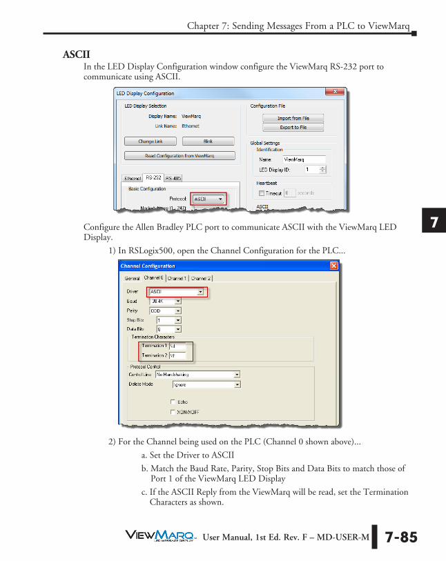
1
2
3
4
5
6
7
8
9
10
11
12
13
14
A
B
C
D
Chapter 7: Sending Messages From a PLC to ViewMarq
7-85 User Manual, 1st Ed. Rev. F – MD-USER-M
ASCIIIn the LED Display Configuration window configure the ViewMarq RS-232 port to communicate using ASCII.
Configure the Allen Bradley PLC port to communicate ASCII with the ViewMarq LED Display.
1) In RSLogix500, open the Channel Configuration for the PLC...
2) For the Channel being used on the PLC (Channel 0 shown above)...
a. Set the Driver to ASCII
b. Match the Baud Rate, Parity, Stop Bits and Data Bits to match those of Port 1 of the ViewMarq LED Display
c. If the ASCII Reply from the ViewMarq will be read, set the Termination Characters as shown.

1
2
3
4
5
6
7
8
9
10
11
12
13
14
A
B
C
D
Chapter 7: Sending Messages From a PLC to ViewMarq
7-86 User Manual, 1st Ed. Rev. F – MD-USER-M
i. \d is a Carriage Return
ii. \ff means not used
3) On the General Tab, for the Channel configured in Step 2...
a. Set the AWA Append Characters as shown below.
i. \d is a Carriage Return
ii. \ff means not used
In order for the PLC to send the String it must be in the PLC Memory as a String Data Type.
1) Copy the ASCII String from the ViewMarq Software.
2) In RSLogix500, open the String data file you are using and paste the ASCII String into the file.

1
2
3
4
5
6
7
8
9
10
11
12
13
14
A
B
C
D
Chapter 7: Sending Messages From a PLC to ViewMarq
7-87 User Manual, 1st Ed. Rev. F – MD-USER-M
Now that the Port has been configured and the ASCII String is in PLC memory, use an AWA (ASCII Write Append) instruction to send the string out the serial port.
1) Select the Channel number that was configured earlier and that is connected to the ViewMarq.
2) For the Source select the String Data Address the ASCII String was Pasted into.
3) Choose an unused Control Address.
4) Enter 82 for the String Length Maximum. For strings longer than 82 characters, see the next section, “Long ASCII Strings”.
NOTE: The AWA instruction is a “Level-enabled” instruction so be sure to put a One Shot (ONS) instruction for the enable.

1
2
3
4
5
6
7
8
9
10
11
12
13
14
A
B
C
D
Chapter 7: Sending Messages From a PLC to ViewMarq
7-88 User Manual, 1st Ed. Rev. F – MD-USER-M
Reading the ASCII Reply
If the “ASCII Reply” option is enabled in the “LED Display Configuration” settings AND you are sending to an ID other than 0, your PLC may Read the Reply Response String that is sent by the ViewMarq LED Display.
Use an ABL (ASCII Test For Line) instruction to check for the Termination characters entered in the Channel configuration and then a ARL (ASCII Read Line) instruction to read in the Status reply response String.
1) For the ABL instruction, select the Channel number that was configured earlier and that is connected to the ViewMarq.
2) Choose an unused Control Address.
3) Trigger the ABL instruction with a normally closed contact using the Control Address Enable to trigger the instruction each PLC scan.
4) For the ARL instruction, select the Channel number that was configured earlier and that is connected to the ViewMarq.
5) Choose an unused Control Address.
6) Trigger the ARL instruction with the Found (FD) bit of the ABL instruction Control Address.

1
2
3
4
5
6
7
8
9
10
11
12
13
14
A
B
C
D
Chapter 7: Sending Messages From a PLC to ViewMarq
7-89 User Manual, 1st Ed. Rev. F – MD-USER-M
If the syntax sent to the ViewMarq display was correct, you will see an “OK” in your Response String. If there is a problem, you will get a Syntax error and the position where the error occurred.
Example of a good String
Example of a syntax error String
Sending Long ASCII Strings
If the ASCII String is longer than 82 characters, multiple String Files and multiple instructions need to be used.
1) Copy the ASCII String from the ViewMarq software.
2) Paste up to 82 characters of the String into the first String File.
3) Paste the up to 82 of the next characters into the next available String File and so on until the entire string is contained in memory.
NOTE: It does not matter where the string is broken apart. It will be assembled again in the ViewMarq display when a Carriage Return character is received.

1
2
3
4
5
6
7
8
9
10
11
12
13
14
A
B
C
D
Chapter 7: Sending Messages From a PLC to ViewMarq
7-90 User Manual, 1st Ed. Rev. F – MD-USER-M
The AWA instruction will always “append” the termination character to the end of the string. To get around this, use the AWT (ASCII Write) Instruction as shown below. The AWT instruction sends the ASCII String out the Serial port WITHOUT the termination character.
Use as many instructions necessary to send each String File triggering the instruction with the Done (DN) bit of the previous instruction. The LAST instruction must be an AWA instruction to send the termination character.

1
2
3
4
5
6
7
8
9
10
11
12
13
14
A
B
C
D
Chapter 7: Sending Messages From a PLC to ViewMarq
7-91 User Manual, 1st Ed. Rev. F – MD-USER-M
ModbusWriting the ASCII String to the Command Block
In the LED Display Configuration window configure the ViewMarq RS-232 port.
1) Set the Protocol to Modbus.
2) Set the LED Display ID to the desired Modbus Node number.
3) Select Byte Swap because Allen Bradley Modbus is the opposite Byte order from ViewMarq Modbus.

1
2
3
4
5
6
7
8
9
10
11
12
13
14
A
B
C
D
Chapter 7: Sending Messages From a PLC to ViewMarq
7-92 User Manual, 1st Ed. Rev. F – MD-USER-M
Configure the Allen Bradley PLC port to communicate Modbus with the ViewMarq LED display.
1) In RSLogix500, open the Channel Configuration for the PLC.
2) For the Channel being used on the PLC (Channel 0 shown above)
a. Set the Driver to Modbus.
b. Match the Baud Rate, Parity, Stop Bits and Data Bits to match those of Port 1 of the ViewMarq LED display.
In order for the PLC to send the String it must be in the PLC Memory as an Integer Data Type.
3) Copy the ASCII String from the ViewMarq Software.

1
2
3
4
5
6
7
8
9
10
11
12
13
14
A
B
C
D
Chapter 7: Sending Messages From a PLC to ViewMarq
7-93 User Manual, 1st Ed. Rev. F – MD-USER-M
4) In RSLogix500 open the Integer data file you are using and paste the ASCII String into the file. Open the Integer data file and change the Radix to “ASCII”.
5) Double click on the first Integer file location and Paste the data in and hit Enter. It should look something like the window below.

1
2
3
4
5
6
7
8
9
10
11
12
13
14
A
B
C
D
Chapter 7: Sending Messages From a PLC to ViewMarq
7-94 User Manual, 1st Ed. Rev. F – MD-USER-M
6) An additional byte (termination) must be added to the end of the data. If the String data is an odd number of bytes, the two termination characters will have to be separated between 2 different Integer addresses. Double click on the first field and add “\d” after the “>”.
If the String data is an even number of bytes, enter in “\0d\00” in the next Integer address after the String data.
NOTE: Please note that when you hit enter, the display changes the \0d to ^M.
Now that the data is prepared, use a MSG (Read/Write Message) instruction to send the data out the port to the ViewMarq Display.
1) Choose an available, unused MG address.
2) Click on the “Setup Screen” option to configure the instruction.

1
2
3
4
5
6
7
8
9
10
11
12
13
14
A
B
C
D
Chapter 7: Sending Messages From a PLC to ViewMarq
7-95 User Manual, 1st Ed. Rev. F – MD-USER-M
3) Select the Channel number that was configured earlier and that is connected to the ViewMarq.
4) Select Modbus Command: 16 Write Multiple Registers (4xxxxx)
5) In the Data Table Address field, enter the starting address of the Integer data file that the copy and pasted data was placed into.
6) The Size in Elements field should be sufficient in size to include all of the populated Integer addresses. For Modbus, this can be up to 120 registers in length. For strings longer than 240 characters, see the section, “Sending Long ASCII Strings over Modbus”.
7) Choose “16 Bit” for the Data field.
8) Leave the Message Timeout at 2. This may need to be increased if the cable quality is suspect or if the environmental conditions are less than ideal.
9) The MB Data Address should be 11000 for the Command Block. This equates to 411000 in Modicon Address style.
10) The Slave Node Address should match the LED Display ID (Node Address) configured in the LED Display for the port you are connecting to.

1
2
3
4
5
6
7
8
9
10
11
12
13
14
A
B
C
D
Chapter 7: Sending Messages From a PLC to ViewMarq
7-96 User Manual, 1st Ed. Rev. F – MD-USER-M
Reading the Status Reply Buffer
After the Modbus Write is successful, the ViewMarq display will process the message. When the display has finished processing the message it will clear the Command Block. The next step of the logic should be to read the 1st element of Command Block until it is 0.
Use another MSG (Read/Write Message) instruction to read the Command Block in the ViewMarq Display.
1) Choose an available, unused MG address. 2) Click on the “Setup Screen” option to configure the instruction.
3) Select the Channel number that was configured earlier and that is connected to the ViewMarq
4) Select Modbus Command: 03 Read Multiple Registers (4xxxxx) 5) In the Data Table Address field, enter an available, unused Integer address that can
be compared to 0. 6) The Size in Elements field should be 1 to read the first word of the Command
Block. 7) Choose “16 Bit” for the Data field. 8) Leave the Message Timeout at 2. This may need to be increased if the cable quality
is suspect or if the environmental conditions are less than ideal. 9) The MB Data Address should be 11000 for the Command Block. This equates to
411000 in Modicon Address style. 10) The Slave Node Address should match the LED Display ID (Node Address)
configured in the LED Display for the port you are connecting to. 11) Keep executing the Read MSG of the Command Block until the 1st element is 0.
Once the value equals 0, the Status can be read.

1
2
3
4
5
6
7
8
9
10
11
12
13
14
A
B
C
D
Chapter 7: Sending Messages From a PLC to ViewMarq
7-97 User Manual, 1st Ed. Rev. F – MD-USER-M
Use another MSG (Read/Write Message) instruction to read the Status Reply Buffer in the ViewMarq Display.
1) Choose an available, unused MG address.
2) Click on the “Setup Screen” option to configure the instruction.

1
2
3
4
5
6
7
8
9
10
11
12
13
14
A
B
C
D
Chapter 7: Sending Messages From a PLC to ViewMarq
7-98 User Manual, 1st Ed. Rev. F – MD-USER-M
3) Select the Channel number that was configured earlier and that is connected to the ViewMarq
4) Select Modbus Command: 03 Read Multiple Registers (4xxxxx)
5) In the Data Table Address field, enter in the starting Integer address of an available, unused Data Block that the Status data can be read into.
6) The Size in Elements field should be 120 to read the first word of the Status Block.
7) Choose “16 Bit” for the Data field.
8) Leave the Message Timeout at 2. This may need to be increased if the cable quality is suspect or if the environmental conditions are less than ideal.
9) The MB Data Address should be 11500 for the Command Block. This equates to 411500 in Modicon Address style.
10) The Slave Node Address should match the LED Display ID (Node Address) configured in the LED Display for the port you are connecting to.

1
2
3
4
5
6
7
8
9
10
11
12
13
14
A
B
C
D
Chapter 7: Sending Messages From a PLC to ViewMarq
7-99 User Manual, 1st Ed. Rev. F – MD-USER-M
After this instruction has been enabled and is successful, the Status Reply can be read by opening the Data File where the Status data was read into and changing the Radix to ASCII.
If the syntax sent to the ViewMarq Display was correct, you will see an “OK” in your Response String. If there is a problem, you will get a Syntax error and the position where the error occurred.
Sending Long ASCII Strings over Modbus
If the ASCII String is longer than 240 characters, multiple files and multiple instructions need to be used.
1) Copy the ASCII String from the ViewMarq Software.
2) Double click on the first Integer file location and Paste the data in and hit Enter. It should look something like the following window.

1
2
3
4
5
6
7
8
9
10
11
12
13
14
A
B
C
D
Chapter 7: Sending Messages From a PLC to ViewMarq
7-100 User Manual, 1st Ed. Rev. F – MD-USER-M
3) An additional byte (termination) must be added to the end of the data. If the String data is an odd number of bytes, the two termination characters will have to be separated between 2 different Integer addresses. Double click on the first field and add “\d\00”.

1
2
3
4
5
6
7
8
9
10
11
12
13
14
A
B
C
D
Chapter 7: Sending Messages From a PLC to ViewMarq
7-101 User Manual, 1st Ed. Rev. F – MD-USER-M
If the String data is an even number of bytes, enter in “\0d\00” in the next Integer address after the String data.
NOTE: Please note that when you hit enter, the display changes the \0d to ^M.
Now that the data is prepared, use multiple MSG (Read/Write Message) instructions to send the data out the port to the ViewMarq Display.
1) In the Data Table Address field, enter the starting address of the Integer data file that the copy and pasted data was placed into.
2) The Size in Elements field should be 120 registers in length for Modbus.
3) Choose “16 Bit” for the Data field.
4) The MB Data Address should be 11000 for the Command Block.

1
2
3
4
5
6
7
8
9
10
11
12
13
14
A
B
C
D
Chapter 7: Sending Messages From a PLC to ViewMarq
7-102 User Manual, 1st Ed. Rev. F – MD-USER-M
Trigger the next MSG instruction with the DN (Done) bit of the previous MSG instruction. The second MSG instruction will pick up where the first instruction left off.
1) In the Data Table Address field, enter the next value of the Integer data file where the last instruction left off. (N7:0 + 120 = N7:120) .
2) The Size in Elements field should be 120 registers in length for Modbus.
3) Choose “16 Bit” for the Data field.
4) The MB Data Address should be 11000+120 = 11120 for the Command Block.

1
2
3
4
5
6
7
8
9
10
11
12
13
14
A
B
C
D
Chapter 7: Sending Messages From a PLC to ViewMarq
7-103 User Manual, 1st Ed. Rev. F – MD-USER-M
Allen Bradley CompactLogix and ControlLogix PLCsThe Allen Bradley ControlLogix and CompactLogix PLCs both utilize RS-232 and the ASCII protocol to send ASCII strings to the ViewMarq LED display
RS-232Connect the ViewMarq Port 1 terminal block to the Allen Bradley 9-pin D-Sub port. The cable for this will need to be constructed by the user.
Allen-Bradley SLC 5-03/04/05, ControlLogix, CompactLogix,FlexLogix, MicroLogix, DF1, RS-232C
To PLC9-Pin Port
9-pinD-sub
(female)1
9
1 = do not use2 = RXD3 = TXD4 = do not use5 = Signal GND
6 = do not use7 = do not use8 = do not use9 = do not use
1 = RS-485 +2 = RS-485 -3 = Signal Ground4 = RS-232 TX5 = RS-232 RX6 = RS-232 RTS
235
RXD
TXD
GND
345 RX
TX
shield
Wiring Diagram
Note: Use the above wiring diagram to make your own cable. We recommend using 22 AWG shielded cable.
To ViewMarqPanel Port1
RS-232
ASCIIIn the LED Display Configuration window configure the ViewMarq RS-232 port to communicate using ASCII.

1
2
3
4
5
6
7
8
9
10
11
12
13
14
A
B
C
D
Chapter 7: Sending Messages From a PLC to ViewMarq
7-104 User Manual, 1st Ed. Rev. F – MD-USER-M
Configure the Allen Bradley PLC port to communicate ASCII with the ViewMarq LED Display.
1) In RSLogix5000, open the Controller Properties for the PLC.
2) On the Serial Port tab
a. Set the Mode to User.
b. Match the Baud Rate, Parity, Stop Bits and Data Bits to match those of Port 1 of the ViewMarq LED Display.
3) On the User Protocol tab
a. Set the Protocol to ASCII.
b. Set the Buffer size to 500 Byte. This is the maximum String the ViewMarq can accept.

1
2
3
4
5
6
7
8
9
10
11
12
13
14
A
B
C
D
Chapter 7: Sending Messages From a PLC to ViewMarq
7-105 User Manual, 1st Ed. Rev. F – MD-USER-M
c. If the ASCII Reply from the ViewMarq will be read, set the Termination Characters as shown.
• Termination Character 1 – ‘$r’ is a Carriage Return
• Termination Character 2 - ‘$FF’ means not used
d. Set the Append Characters as shown. These will be appended to the end of the String that is sent.
• Append Character 1 – ‘$r’ is a Carriage Return
• Append Character 2 - ‘$FF’ means not used
In order for the PLC to send the String it must be in the PLC Memory. A String data type 500 characters long is needed.
1) In RSLogix5000 create a new String Data Type.
2) Set Maximum Characters to 500.
Use this new String Data Type when creating new strings to send to the ViewMarq.

1
2
3
4
5
6
7
8
9
10
11
12
13
14
A
B
C
D
Chapter 7: Sending Messages From a PLC to ViewMarq
7-106 User Manual, 1st Ed. Rev. F – MD-USER-M
7) Create a New String Tag using the Data Type just created.

1
2
3
4
5
6
7
8
9
10
11
12
13
14
A
B
C
D
Chapter 7: Sending Messages From a PLC to ViewMarq
7-107 User Manual, 1st Ed. Rev. F – MD-USER-M
8) Create a New Tag using the predefined SERIAL_PORT_CONTROL Data type.
9) Copy the ASCII String from the ViewMarq Software.

1
2
3
4
5
6
7
8
9
10
11
12
13
14
A
B
C
D
Chapter 7: Sending Messages From a PLC to ViewMarq
7-108 User Manual, 1st Ed. Rev. F – MD-USER-M
10) In RSLogix5000 open the String data file just created and paste the ASCII String into the file.
Now that the Port has been configured and the ASCII String is in the PLC Tag, use an AWA (ASCII Write Append) instruction to send the string out the serial port.
1) Select the Channel number that was configured earlier and that is connected to the ViewMarq.
2) For the Source select the String Data File the ASCII String was Pasted into. 3) For the Serial Port Control choose the SERIAL_PORT_CONTROL tag created
above.

1
2
3
4
5
6
7
8
9
10
11
12
13
14
A
B
C
D
Chapter 7: Sending Messages From a PLC to ViewMarq
7-109 User Manual, 1st Ed. Rev. F – MD-USER-M
Reading the ASCII Reply
If the “ASCII Reply” option is enabled in the “LED Display Configuration” settings AND you are sending to an ID other than 0, your PLC may Read the Reply Response String that is sent by the ViewMarq LED Display.
1) Create a New String Tag using the new String Data Type created.

1
2
3
4
5
6
7
8
9
10
11
12
13
14
A
B
C
D
Chapter 7: Sending Messages From a PLC to ViewMarq
7-110 User Manual, 1st Ed. Rev. F – MD-USER-M
2) Create a New Tag using the predefined SERIAL_PORT_CONTROL Data type.

1
2
3
4
5
6
7
8
9
10
11
12
13
14
A
B
C
D
Chapter 7: Sending Messages From a PLC to ViewMarq
7-111 User Manual, 1st Ed. Rev. F – MD-USER-M
Use an ABL (ASCII Test For Line) instruction to check for the Termination characters entered in the Channel configuration and then an ARL (ASCII Read Line) instruction to read in the Status reply response String.
1) For the ABL instruction, select the Channel number that was configured earlier and that is connected to the ViewMarq.
2) For the Serial Port Control choose the SERIAL_PORT_CONTROL tag created above.
3) Trigger the ABL instruction with a normally closed contact using the Control File Enable to trigger the instruction each PLC scan.
4) For the ARL instruction, , select the Channel number that was configured earlier and that is connected to the ViewMarq.
5) For the Serial Port Control choose the SERIAL_PORT_CONTROL tag created for Read Reply above.
6) Trigger the ARL instruction with the Found (FD) bit of the ABL instruction Control File.
If the syntax sent to the ViewMarq Display was correct, you will see an “OK” in the String Tag . If there is a problem, you will get a Syntax error and the position where the error occurred.