senior design 1 - departments of ece and cs - home · 2016-05-01 · senior design 1 fall 2015...
TRANSCRIPT

1
Senior Design 1
Fall 2015
Group 29
Tanner Foster
Justin Yuen
Ehsan Falaki Matt Szewczyk

i
Table of Contents 1. Executive Summary ............................................................................................... 1
2. Project Description ................................................................................................. 2
2.1. Motivation ........................................................................................................ 2
2.2. Goals and Objectives ...................................................................................... 3
2.3. Specifications Requirements ........................................................................... 4
2.3.1. Drone Specifications ................................................................................. 4
2.3.2. Ground Vehicle Specifications .................................................................. 4
3. Research ............................................................................................................... 5
3.1. Existing Similar Projects and Products ............................................................ 5
3.2. Ground Vehicle ................................................................................................ 6
3.2.1. Hardware .................................................................................................. 6
3.2.2. Ground Station Computer ......................................................................... 9
3.2.3. Motor Controllers .................................................................................... 13
3.2.4. Sensors ................................................................................................... 17
3.2.5. Power Systems ....................................................................................... 19
3.3. Aerial Vehicle ................................................................................................ 25
3.3.1. Frame ..................................................................................................... 25
3.3.2. Flight Controller ...................................................................................... 30
3.3.3. Communication ....................................................................................... 32
3.3.4. Motors ..................................................................................................... 33
3.3.5. Propellers ................................................................................................ 37
3.3.6. Power Supply .......................................................................................... 39
3.3.7. Electronic Speed Controllers .................................................................. 43
3.4. Intercommunication ....................................................................................... 46
3.4.1. Ground Vehicle - Aerial Vehicle .............................................................. 46
3.4.2. Image Processing to Ground Vehicle Control ......................................... 49
3.5. Image Processing and Implementation ......................................................... 50
3.5.1. Edge Detection ....................................................................................... 50
3.5.2. Maze Detection ....................................................................................... 52

ii
3.5.3. Maze Solving .......................................................................................... 56
3.5.4. Image to Code Conversion ..................................................................... 59
4. Design .................................................................................................................. 62
4.1. Ground Vehicle Hardware ............................................................................. 62
4.1.1. Motor Controller to Embedded Processor Design ................................... 62
4.1.2. Sensor Interface ..................................................................................... 64
4.1.3. Voltage Stepper and Battery Eliminators ................................................ 65
4.1.4. MSP430 UART Communication ............................................................. 69
4.2. Overall PCB Design ...................................................................................... 71
4.3. Software ........................................................................................................ 73
4.3.1. Ground Vehicle ....................................................................................... 73
4.3.2. Quadcopter ............................................................................................. 86
4.3.3. Image Processing ................................................................................... 89
4.3.4 Full Build Materials List ............................................................................ 97
5. Prototyping ......................................................................................................... 101
5.1. Stage 0 Prototypes ...................................................................................... 101
5.2. Stage 1 Prototype ........................................................................................ 101
5.3. Stage 2 Prototype or Final Prototype .......................................................... 102
6. Testing ............................................................................................................... 103
6.1. Maze Design ............................................................................................... 103
6.2. Image Processing ........................................................................................ 104
6.2.1. Setting Up the PI and Installing the Requirements ............................... 104
6.2.2. Maze Identification ................................................................................ 105
6.2.3. Maze Required Resolution .................................................................... 106
6.3. Ground Vehicle Control ............................................................................... 107
6.3.1. Sensors ................................................................................................. 107
6.3.2. Motor Control ........................................................................................ 108
6.3.3. Vehicle Orientation ............................................................................... 109
6.4. Aerial Vehicle Control .................................................................................. 111
6.4.1. Propellers .............................................................................................. 111
6.4.2. Battery Capacity ................................................................................... 112

iii
6.4.3. Flight Stability ....................................................................................... 112
6.4.4. Altimeter ................................................................................................ 115
6.4.5. Global Positioning ................................................................................. 116
6.4.6. Automated Control ................................................................................ 116
6.5. Integration ................................................................................................... 118
6.5.1. Computer Application............................................................................ 118
6.5.2. Transmitting and Receiving .................................................................. 118
7. Standards .......................................................................................................... 120
7.1. AC 91-57A Model Aircraft Operating Standards .......................................... 120
7.2. FCC 15.247 ................................................................................................. 121
8. Appendices ........................................................................................................ 126

1
1. Executive Summary Our project, titled The Maze Zone Drone (MZD), is a multi-system communication effort requiring both hardware and software collaboration to achieve success. Combining both a ground vehicle with the support of an aerial vehicle, the goal is for the quadcopter to provide enough information to assist the ground vehicle in navigating a maze on the first attempt. From the air, this entails locating desired points of interest, autonomous image processing, and transmitting data. On the ground, this entails receiving data, a maze solving algorithm from the image, and logic to navigate the maze. However, this is the most basic of overviews, as the hardware and software specifications dive into much more detail. There is an increasing chance for failure with each added component. To implement this setup, the team will be constructing a wooden maze, made from 2x4 planks of framing lumber painted black. Assembled on a white concrete backdrop, the maze walls will be easily distinguishable for image processing from above. LEDS will also be used for scaling and locating points of interest. Aside from the chassis, the aerial vehicle will feature flight controllers, flight sensors, a transmitter/receiver, camera, electronic speed controllers, and a power supply system. The portable quadcopter should be easy to manually control with autonomous stabilization and hovering capabilities. The ground vehicle features the ground station computer, motor controllers, ultrasonic sensors, transmitter/receiver, and a power system, among other details. Once wireless communication is received from the MZD camera, the ground vehicle will then be able to navigate the mazes shortest path autonomously and quickly. To prepare for this undertaking various hardware and software platforms will be investigated. A semester worth of research and design is dedicated before a working prototype is hopefully completed early into senior design 2. This will allow enough time for testing and meeting the specifications. Enhancements and adjustments can be made upon full functionality. To design this system, the design team is composed of two senior electrical engineering students and two senior computer engineering students. The electrical engineers will focus on the hardware design aspects of this project, which include the ground vehicle motor controllers and air vehicle flight controllers. The computer engineers will focus on the software design aspects of this project, including the image processing, vehicle sensor and navigation, and computer application for intercommunication. The design team would like to thank these sponsors Soartech and Boeing for putting their name on the design and funding the project. Thank you!

2
2. Project Description
2.1. Motivation
The motivation for this senior design project began with an intense interest among the members of the group into integrating a drone into the core of their project. The first idea pitched was an autonomous drone that could image large swaths of farmland and track crop growth. However, the team scaled back these ambitions and settled on a drone-car pair that can solve mazes using computer vision and guide the car to its destination. It was a relatively easy decision that stemmed from some interesting motivation, and derived a few of the following implementations.
The Maze Zone Drone (MZD) is the first step in reducing the stresses of finding a parking spot in a crowded parking lot. Future ambitions could enable a user to release their MZD out the window of their car at the entrance of a parking lot, allow the MZD to find a parking spot, calculate the shortest path to the spot, and even guide the vehicle to the spot with the press of button. The team wanted the drone to be able to communicate directly to the vehicle and for the drone to be controlled by the same vehicle to simulate a realistic environment. This project also has potential military applications as well, as the quadcopter drone can be made to be modular to include a variety of sensors to detect infrared and potentially thermal obstacles and plot a course around them. Prior to these implementations, one of the early motivators was also military based. It originated from an article regarding the alarming failure of helicopter landings in the extreme terrains of the world. Particularly the huge dust blowback created from landing in the desert. The military even has a term for this event, a brown out, displayed in Figure 2.1.
(Figure 2.1 illustrates the term “brown out”)

3
The pilot is essentially blind and equipment readings are not always accurate. It was shocking to find that a military pilot fatality actually arose from such an occasion. There were many suggestions to resolve this issue. A feasible solution was to send a detachable mini drone out and above the helicopter, providing real-time aerial footage to assist the pilot. The drone assists the pilot in a similar way the MZD should guide the ground vehicle. This military idea in combination with a few existing similar projects, proved that it could be done and helped shape the project the group are undertaking today. The technologies bringing the MZD to life will require a high level of attention to detail and dedication from the design team. The immediate goal of detailed research and design will ensure success during prototyping. After months of planning, it will be incredibly rewarding to fine tune and observe the drone-car pair as it comes to fruition. As candidates for graduation in the field of engineering, this project simulates how engineers collaborate in the actual workforce. The design team is highly motivated for project success, in anticipation of discussing and demonstrating the pinnacle display of knowledge amassed over the course of undergraduate study.
2.2. Goals and Objectives
The success of this project is defined on culmination of the goals and objectives the team establishes. A list of feature and performance requirements are derived from these goals and discussed in the next section. The ultimate objective is to design and build a fully functional multi-system project. It should efficiently communicate autonomously for the purpose of maze solving, yet remain modifiable for other implementations. The transitional goals are as follows:
Complete the research to ensure component success and safety Order all required parts by the end of the first semester Develop each subsystem individually with requirements from neighboring
systems taken into consideration Unify electrical components Integrate software code Create prototype to utilize for testing with basic functionality by early Spring
2016 Actively test the system using all situations detailed in testing (Best Case Vs.
Worst Case Scenarios) Further increase durability and aesthetics by weatherproofing and improving
structural integrity By assigning specialized subsystem research to respective design team members, the team can collaborate efficiently to ensure coverage of all goals and specifications (detailed in the next section). Once these goals have been met, the design team will have the opportunity to present the project to sponsors and peers at the end of the second semester. Any expansions not critical to the project requirements can be considered given extra development time.

4
2.3. Specifications Requirements
The following list of specifications was agreed upon after some discussion about what the project was meant to accomplish defined in the previous section. These specifications are meant to create achievable goals a sophisticated project beyond what could be considered just the bare minimum. While modifiable, following the core specifications will focus the team’s interests efficiently during its various prototyping phases. Starting with the hardware portion and working back to the application portion, the feature and performance requirements are listed.
2.3.1. Drone Specifications
Maximum of 1 meter diameter (propeller to propeller) Maximum of 2 kilograms Minimum 10 minute hover time Wireless communication up to 30 meters Altitude accurate within 2 meters up to 50 meters Global Position Hold accuracy within 2 meters
-The drone should be small enough and light enough for a single person to easily transport and deploy and robust enough to withstand mishaps that may occur with the average untrained pilot. -It should also automatically assist the pilot during manual control for ease of use and have the option to set an autopilot mode that will hold the drone stable above the maze at a set altitude and lateral coordinate in order for the camera to acquire a stable view of the maze and the ground vehicle. -The drone should be able to use computer vision to locate and capture the maze from the air, without utilization of a separate central computer.
2.3.2. Ground Vehicle Specifications
Less than 0.5 cubic meters in size. Able to run for at least fifteen minutes. Housing the processing core, or able to communicate with an outside
processing core. Able to move at least 1/6 meters per second
The ground vehicle should contain the main processing unit for all the image processing and manipulation as well as have the wireless communication infrastructure to communicate with both the radio control interface on the quadcopter as well as the camera wireless module. The ground vehicle should also have a motor controller that communicates to the main processing unit for instruction, this motor controller should also allow for the connection of ultrasonic sensors that allow it to sense the walls of the maze to better guide it along its path and to allow the air vehicle to only take one photo for ease of processing.

5
It should also have a unique identifier, either in shape form or in coloring scheme, which will make it easy for the image processing software to identify where in the maze the ground vehicle is.
3. Research The following section envelopes preliminary research developed by all team members on their respective system for this project. The knowledge attained from this research section builds on an analysis of existing systems, retrofitted to the specifications. After discussing some similar projects within UCF, the background behind the ground vehicle, aerial vehicle, intercommunication, and image processing will be addressed.
3.1. Existing Similar Projects and Products
After exploring the UCF senior design homepage, one of the projects that set the foundation for this project, was a 2010 group project called Autonomous Drones. A description from their senior design blog reads, “The main objective of our project was to have drones autonomously solve a maze while being able to communicate information to each other wirelessly.” They used infrared sensors, a range finder, and simple software to make the drones turn left or right. It’s a somewhat tedious process, moving block by block through the maze, returning to the start, and beginning again. The structure of the maze is stored and communicated wirelessly to make sure not to visit a square that has already been explored. The maze is essentially partitioned between the two drones, effectively turning a large maze into a number of small mazes.
The team was predestined on implementing a drone into this Senior Design project. So combining ideas, as well as some of the motivation mentioned previously, the group would be implementing autonomous maze solving vehicles. However, instead of ground vehicles learning from the failure of wrong paths taken, the group would be utilizing a quadcopter, in autonomous communication with a ground vehicle, to solve the maze on the first get-go.
The 2010 project proved to show that not only was that this project feasible, but successful. Communication between two vehicles was possible, and this project had its own original twist. The group would be able to use it as a reference point on to what sensors and maze construction were used, although the group modified those as well.
Having an original project idea, that the group knew could be implemented, allowed the project to be sponsored by both Boeing and Soartech. The group was pleased to find out it was the only group in the class who had gotten funding from Soartech, in the amount of $1,000. Upon meeting with our advisor, he mentioned how last year they sponsored a surprisingly similar idea, which included quadcopter to ground vehicle communication, but with a different purpose. Although similar, the group was chosen for an original twist on an exciting idea, with background knowledge on our

6
resumes to prove the group could be successful. It was found that the group was called Drone Hunt and their project was a type of duck hunting drone system.
3.2. Ground Vehicle
3.2.1. Hardware
3.2.1.1. Chassis
The chassis for the ground vehicle needs to be small enough to navigate a maze yet large enough to house all the components, sensors, and batteries that will be mounted. In the beginning the group was unsure as how to build this portion of the craft and it was suggested that a simple plastic housings for all the sensitive electronic components that would be stacked on a commercial RC car chassis would be sufficient. Luckily the group had the good fortune to be given a premade prototyping chassis by the instructor which will suit the needs of the project.
(Figure 3.1 shows the chosen chassis)
The chassis that was donated was the Pololu Dagu Wild Thumper chassis which is seen in Figure 3.1. It is a reasonably lightweight aluminum chassis at 4.1 lbs. and is covered with 4mm holes that will make it easy to mount the planned pcbs and computer systems along with any other modules needed as they are needed. [3]

7
The built in size 34:1 gearboxes house four DC motors that can get the job done without full power, max input of 7.2V. The output shaft speed is 350 RPM, or around 4 mph. This is much higher than the required ⅙ meter per second speed listed in the specifications. With 4 wheel-drive and an independent suspension for each tire, this type of chassis is built for rough, outdoor use. However, the suspensions are adjustable and there are many unique implementations of the chassis thanks to the 4mm holes. [3]
A compartment below the chassis is included to house two sub battery packs, which can then be connected to the motor drive leads. A battery life of at least 15 minutes will have to be insured as per specifications. The overall chassis and tires are relatively large, considering the fact that a maze is still confined space. The area of the Dagu Wild Thumper combines for 11”x12”x5”, or about a square foot with all components loaded on. [3] An issue with the previous group was too much tire traction on the given tires. Some slippage is required to fully rotate in a confined space, as is further discussed in the wheels section.
3.2.1.2. Motors
The motor system for the ground vehicle needs to be able to propel it at a reasonable rate once the overhead drone has sent the central computer the picture of the maze. It must also propel the vehicle efficiently and without power fluctuations that might power off the main computer. For this the group considered a few different motor systems and came down to two separate systems that could work for the design, servos and brushed DC motors. Servos have a three wire connection: power, ground, and control. The control circuits are built right into the motor, so the group would not have to do any pulse width modulation design and analysis to get them to work correctly. They are generally lightweight and easy to control once you have all them calibrated, however they need a constant supply of power. Therefore they are generally weaker than brushed DC motors and operate at lower, more controlled rpms. DC motors are only a two wire connection, and do not have the internal circuits as the servos do. Its speed, or power levels would have to design control circuits and properly calibrate them using pulse width modulation to vary and control the speed at which they spin. That gives the group the option of very high speeds if it is need it as compared to the servos, however calibrating the motors may take longer than calibrating the servos. Taking all this into account, including the fact that the group has received the motors pictured in Figure 3.2 along with the chassis, the brushed DC motors will work better for this project. Specifically the ground vehicle will be using 34:1 gearbox motors that are rated at 4mph at 7.2V. To achieve more manageable speeds it is likely that it will

8
be possible to create a system using pulse width modulation to regulate the rpm of the motors. [14]
. (Figure 3.2 shows the chosen motor)
3.2.1.3. Wheels
From the beginning the group were interested in the wheels as a way to reduce the time taken to reduce the time required to solve the maze. For this the group were interested in to wheel systems primarily, the mecanum wheel system and an all-wheel drive standard tire system. The mecanum wheels utilize roller along the wheel face set at 45° to the angle of rotation of the wheel. With these rollers in place and the drive system finely tuned the vehicle would be able to traverse in all directions, forward-backward and side to side without having to turn the whole vehicle. The would be advantageous for maneuvering in a smaller maze where turning would be both awkward for the vehicle and increase the time to completion. These wheels, however, are expensive and difficult to use in certain terrain such as grass and concrete which would make testing the system restricted to only a few locations. The all-wheel drive system would use more standard high traction tires connected to the motors. These tires are both cheap and easy to work with as the mechanics do not have to be coded into the embedded processor. They are however primitive in their use and require the entire vehicle to rotate when it reaches a turn. Some of this awkwardness can be compensated for by utilizing the all-wheel drive aspects of the system and using tank rotation maneuvers perfected by tank crews during World War Two, where one side of the vehicle would run its treads in forward and the other in

9
reverse to rotate on a dime. This can solve the awkward turning problem in a tight maze but increases the need for precision in the system when calibrating every motor. Ultimately it was decided that the All-Wheel Drive system with standard tires fits the project criteria better than the mecanum wheel system. They are cheaper and easier to work with in the long run which will decrease the calibration time and precision needed to achieve satisfactory results. The specific wheels that will be used in the final prototype, which are pictured in Figure 3.3, were donated along with the chassis as a part of the Dagu Wild Thumper kit. The wheels are large, at 120mm had so much traction that they were duct taped in an overlapping manner. Some slippage is required to fully rotate in a confined space.
(Figure 3.3 shows the chosen wheel)
3.2.2. Ground Station Computer
The Ground Station Computer (GSC) has a few basic requirements as the command and control center for both the ground vehicle and the overhead drone alike. It must have: 1. A small form factor to be able to fit on the ground vehicle chassis 2. A low power consumption so that it may run off the battery power supplied by the batteries in board 3. A processor capable of running all out software concurrently. 4. Have sufficient memory to run all the software concurrently. 5. Have sufficient I/O capabilities to interface with all the hardware. 6. Be low cost and low maintenance.

10
Feature Rasp PI 2 B
Beagle Bone B
Odroid C1+
Rock2 Square Beta
NanoPC T1
Humming Board-i2
Processing Speed
900 MHz Quad Core
1 GHz ARM A8
1.5GHz Quad Core
2GHz Quad Core
1.5GHz Quad Core
1 GHz Single Core
Memory RAM
1GB DDR2
512MB DDR 3
1GB DDR3
2GB/4GB 1 GB DDR3 1 GB DDR3
Storage Micro SD
4GB eMMC
Micro SD
Up-to 128GB SSD+
8GB eMMC + SD Card
Micro SD
EthernetWi-Fi Bluetooth Mbps
1 10/100 1 10/100
1 1000
1000+ Bluetooth
100 1000
HDMI Output
1 1 Micro 1 1 1
Composite Video
1 NA NA NA NA NA
Number of USB Ports
4 2 4 2 1 Micro 2 Full
2 USB 2
Audio NA NA NA SPDIF, Headphone Line in- MIC
3mm Audio Jack
NA
Camera Ports
2 NA NA NA NA NA
Power 5V 5V 5V 2A 5V 3A 5V 2A 5V 2A
Size 2.44”x 1.18”
3.4”x 2.1”
3.23”x 2.28”
3.23”x 2.36” 3.93”x 2.36” 85mm x 65mm
Price $ 40 55 37 99 67 75
(Figure 3.4 show a comparison of various ground control stations) [15][16][17][18][19][20]
In Figure 3.4 above the various specifications of the various commercial, low footprint, micro computers can be found. These computers were compared on several levels

11
and every aspect of each was looked at to come down to a final three boards to be chosen from. Taking the first two requirements into account what is left is a number of small form factor computers that can be considered for this project. The Raspberry Pi 2 Model B by adafruit, the HummingBoard-i2 from SolidRun, and the BeagleBone Black from beagleboards.
3.2.2.1. Processor
For this project, the processor has several characteristics that make any single computer system attractive. Aside from actually benchmarking each processor for performance on the software that this whole system will run on there are two main characteristic that will be considered, processor clock speed and number of cores. From the Figure 3.4 the core breakdown for the three selected boards can be discerned. The Software requirements for the GSC and the variety of different programs that are going to be running concurrently means that multiple cores would enhance performance which could be critical when the group is testing as any holdup in processing could result in the overhead drone falling out of the sky or the ground vehicle getting lost in the maze. For this reason the Raspberry PI followed by the BeagleBone Black come out ahead of the HummingBoard with four and two cores respectively. These board will need to run a full Linux operating system to run the kinds of programs that are anticipated to be running so the higher the clock rate generally the better the board will perform. As a result of this the HummingBoard-i2 and BeagleBoard Black come out slightly ahead of the Raspberry Pi 2 Model B, however in light of the multi-core advantage that one would see from the Pi board or the Black board the HummingBoard does not have that great of an advantage over either board.
3.2.2.2. Memory
As can be seen in the Figure 3.4 above, the three boards chosen for further review have similar memory specifications, however there are some important differences between each of the three. The Raspberry Pi board has 1GB of DDR2 ram on board, the BeagleBoard has 512MB of DDR3 ram on board and the HummingBoard has 1GB of DDR3 ram on board. [15] [16] [20] Again as a requirement for the software the memory performance will be a significant factor in how well the system performs overall. Generally the more memory one has in their system the more programs they will be able to run concurrently and those with a more recent DDR architecture will be able to fetch and store information from memory far more quickly. Based on the raw numbers of how much memory each board has, the Raspberry Pi and the HummingBoard come to a tie, both systems have 1GB of RAM compared to the 512MB of ram that the BeagleBone has. This gives

12
them a great advantage over the number of concurrent programs that each can run which will be necessary for the project. Between these two boards however there is an important difference in RAM architecture that sets the boards apart. The Raspberry Pi board is using a DDR2 which, which is an older and slower architecture compared to the HummingBoard which is using a DDR3 chip. The difference between these two chips means that the HummingBoard will be able to not only load and swap out programs from tertiary storage much more quickly, but processor to memory instructions will also be positively affected.
3.2.2.3. I/O
The I/O capabilities for the board are important, but beyond the basic necessities of each module that connects to it that are needed on the project, unfortunately more is not better in this case and in some cases only serves to increase the overall cost of the board. The bare necessities for this board to communicate and control all the modules are as follows:
USB ports to connect with various modules. UART for communication with the microprocessor. Various GPIO as needed.
The HummingBoard has 26 pins for GPIO, UART, and power as needed and two USB ports as compared to the Raspberry Pi 2 Model B which has 20 pins for GPIO and UART plus four USB ports and one micro USB port for power and the BeagleBone Black which has a hefty 92 pins for GPIO and probably UART (Not specified) along with two USB ports. [15] [16] [20] The pins for UART and GPIO are not specifically important beyond just needing to be there, the more is not the merrier in this case. The USB port, however, are a different story. Many module that may end up being using to interface with the GSC may end up requiring a USB connection to properly work. In this regard the Raspberry PI 2 Model B comes out slightly ahead of the other two boards.
3.2.2.4. Price
As can be seen in the Figure 3.4, the price breakdown for the three boards selected for further review are as follows, the Raspberry Pi at $39.95 per unit [15], the BeagleBone at $55.00 per unit [16] and the Hummingboard at $75 per unit [20]. There is a specific capital crunch for this project as the most expensive components that will be used are going to be associated with the drone itself, so the reduction of costs elsewhere is important. From just a cursory overview of the prices the Raspberry Pi would seem like the best choice in this category at a mere $39.95, however more goes into the value of a board like this than simply the final cost of it. The build quality and how much of each resource you are getting per dollar is also vitally important. This

13
this respect the Raspberry Pi also comes out on top, as the 1GB of memory, quad core processor and abundance of GPIO pins means it is the most cost effective option.
3.2.2.5. Ground Station Computer Choice
The Raspberry Pi 2 Model B, which is pictured in Figure 3.5, was ultimately the best choice for this project. The multi core capabilities of the board, along with its large memory capacity and the price per unit all point to it being the ideal and most cost effective board for the job. It has a few shortcomings, such as the older DDR2 RAM modules and the relatively low amount of GPIO pins available to it, however the pros outweigh the cons in this case as the processor and the size of the RAM module make up for the slower speed.
(Figure 3.5 shows the chosen computer, the Raspberry Pi 2 Model B)
3.2.3. Motor Controllers
The motor controllers for the ground vehicle have a few basic necessities and are overall very important to the overall functionality of the vehicle. They must be able to interface and take instruction from a central embedded processor, they must be able to drive the four motors at an acceptable rate and operate at 14V in accordance with the batteries that were donated.
3.2.3.1. Embedded Processor
The embedded processor that will be mounted on the PCB will need to be lightweight and low power yet still be able to accept commands from the GSC. In addition to that

14
the embedded processor will need to be able to accept input from sensors and output instructions to the motor controllers as needed. Taking all these necessities into account the group decided to go with either the MSP430G2553 or the Arduino Uno chipsets as they fulfill every criteria and every member of the group is familiar with programming in either system’s preferred language. Both boards are lightweight and low power, but several differences makes one more suitable than the other.
TI Launchpad Arduino Uno
Microcontroller TI M430G2553 ATMega328
Data Bus 16 bit 8 bit
Speed 16 MHz 16 MHz
Storage 16 KB 32 KB
RAM 512 B 2 KB
Digital I/O 8 channels 14 channels
Analog I/O 8 channels 6 channels
Kit cost $4.30 @ TI.com $29.95 @ Adafruit
(Figure 3.6 shows a comparison of two microcontrollers) [12] [13] The Figure 3.6 above shows the basic breakdown of the two chips based on a multitude of factors. Both chips operate at a 16MHz clock speed, but that’s where the similarities end. The Arduino has a larger storage capacity and nearly 4x the amount of RAM over the MSP430 model was looked at, however the MSP430 has a standard 16 bit data bus and costs only one sixth of what the Arduino Uno does. [12] [13] This project has also been banned from using Arduino boards to encourage the design of embedded systems on a circuit level so the MSP430 is the most suitable system for this project. The MSP430G2553 is a low power system with a voltage range of 1.8V to 3.6V with an active power draw of 130 µA and has 20 pins for various purposes. [12] This range of power requires the group to step down the voltage from the main battery supply to run the processor at an acceptable voltage range. The 20 pins available to the group are limited by VCC, TST, and GND, as well as the pins that are expected to be used for UART between it and the GSC. [12] The rest will be divided up between the various sensors that will be on board and motor controllers themselves. Programming of this embedded processor can be done in a variety of environments, from a text editor to a full blown IDE such as Code Composer Studio. However, for this project, since it is planned to use part that are more commonly found in an Arduino dev kit, it was decided have decided to code the embedded using the Energia IDE which allows for easy integration between the MSP430 and the non-native Arduino components that will be used. An example of this IDE can be seen below in Figure 3.7.

15
(Figure 3.7 shows the Energia IDE)
3.2.3.2. Motor Controller Circuits
The motor controller circuit, which will be the core of the ground vehicle, is rather simple to create and comes as its own self-contained unit when using the chipset that was chosen. The SN754410 motor controller chipset from TI offers self-contained circuits that can be connected straight into the vcc and ground of the motor. This chip has the option of using the enable pins to apply a PWM (Pulse Width Modulation) effect to the motor, which will be useful for course correction as the vehicle traverses the maze. The chip has the specifications seen below in Figure 3.8 and the recommended voltage values are seen below in Figure 3.9.
(Figure 3.8 shows the maximum values of the SN754410 chip) [2] Reprinted with
permission from Texas Instruments.
16
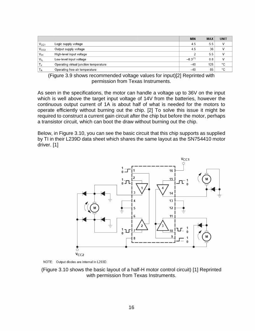
(Figure 3.9 shows recommended voltage values for input)[2] Reprinted with
permission from Texas Instruments. As seen in the specifications, the motor can handle a voltage up to 36V on the input which is well above the target input voltage of 14V from the batteries, however the continuous output current of 1A is about half of what is needed for the motors to operate efficiently without burning out the chip. [2] To solve this issue it might be required to construct a current gain circuit after the chip but before the motor, perhaps a transistor circuit, which can boot the draw without burning out the chip. Below, in Figure 3.10, you can see the basic circuit that this chip supports as supplied by TI in their L239D data sheet which shares the same layout as the SN754410 motor driver. [1]
(Figure 3.10 shows the basic layout of a half-H motor control circuit) [1] Reprinted
with permission from Texas Instruments.

17
3.2.3.3. Communication between systems
Communication between the motor controller and the embedded processor will be simple binary signals that will result in either a clockwise, a counter clockwise, or a no movement of the motors based on the circuit which is displayed above. The motor controllers, by their design, will require two pins from the embedded processor per motor to achieve both forward and backward motion. Figure 3.11 shows the specific logic table for enabling different turning directions on an attached motor in this configuration. [1]
(Figure 3.11 shows the logic needed for controlling the motor controller) [1]
Reprinted with permission from Texas Instruments.
3.2.4. Sensors
Sensors on the ground vehicle will be used for one specific purpose, to sense the walls of the maze and to prevent collision and failure of the project. The purpose of placing sensors on the ground vehicle is to reduce the need for constant computer-vision analysis supplied from overhead by the drone, which would be limited by the processing power of the ground vehicle and the battery life of the drone.
3.2.4.1. Ultrasonic Sensors
Ultrasonic sensor, specifically the SR-04 Module work on the principle of sending out a sound wave that will then bounce off an object in the way of the sound projector and be returned to the sensor. The time it takes for the sound wave to make its full round trip is then analyzed to work out the specific distance an object is from the sensor. The SR-04 Sensor in particular utilizes 4 pins, VCC 5V, GND, SIG IN, SIG OUT, so as a downside of this type of sensor is the sheer number of pins you need if you have more than one on a vehicle. [21] The sensor however is incredibly useful for the project as it gives an accurate and consistent way to measure the distance any side of the vehicle is from the walls of the

18
maze at any one time. With this type of sensor it is possible to keep the vehicle centered on the path of the maze and even do motor adjustments on the fly. You can also determine where you are in the maze by analyzing the four point shape of the maze around it using the characteristics of all the different types of turns.
3.2.4.2. Infra-red Sensors
IR sensors are useful for this project as they, like the ultrasonic sensors, can operate without needing a physical feedback. The simplest of such systems would be similar to the IR Proximity Sensor for Line Follower and Obstacle sensing robots. This module has a range of 10-15cm and runs on a standard 5V DC. [23] This module also only uses one pin for communication out, high or low to signal something is in the path, which would be useful in reducing the complexity of the overall vehicle. A system built on this type of sensor would need to be carefully designed so that the maze that it eventually solves and traverses does not confuse the sensors. These sensors do not output a distance back to the controller, simply a high/low value as to whether an object is within the view range, unlike the ultrasonic sensor which can measure the return time. Drift control would also be difficult to code and design on the hardware level as again you have no way to telling the distance returned from this module. These sensors would be useful if it is planned to make a maze using black tape to designate the path on the ground and have the vehicle follow that tape until it encounters a turn in the tape, but for mazes that are constructed with physical walls this type of sensor is less suited to the task than the ultrasonic sensor.
3.2.4.3. Touch Sensors
Touch sensors would be the most simplistic approach to sensors on the ground vehicle as well as the easiest to implement. The sensors would be comprised of sensitive push switches on the PCB that would be connected to “Whiskers” or long metal wire that stick out to the sides and from of the craft. When these whiskers encounter a wall they will press on the switch alerting the embedded processor that it is approaching a wall, allowing the vehicle to adjust as needed. A vehicle built on this system would not be able to sense a variety of turns unless both the ground vehicle and software are creatively designed. As such a vehicle built on this system would be limited to mazes that make only right or left turns and would be prone to failure should any of the sensors get stuck or oscillate once the pressure from a wall is relieved, either on a turn or when experiencing drift. These sensors are useful if the project is under a funding crunch, as they are the cheapest and easiest to implement, however they lack the accuracy and the functionality that the ultrasonic sensor brings and the increased distance that the IR
19
sensors bring. The also use the fewest pins as only one pin is needed to detect a completed circuit created by the pressing of the switch.
3.2.4.4. Sensor Choice
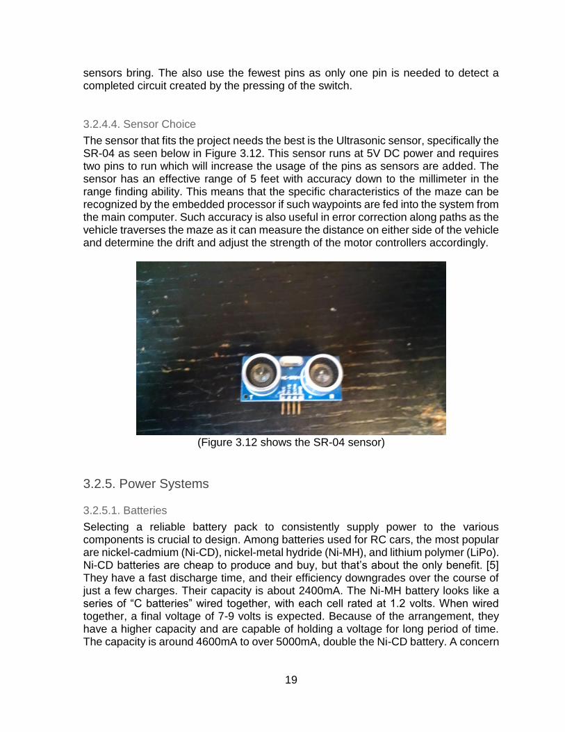
The sensor that fits the project needs the best is the Ultrasonic sensor, specifically the SR-04 as seen below in Figure 3.12. This sensor runs at 5V DC power and requires two pins to run which will increase the usage of the pins as sensors are added. The sensor has an effective range of 5 feet with accuracy down to the millimeter in the range finding ability. This means that the specific characteristics of the maze can be recognized by the embedded processor if such waypoints are fed into the system from the main computer. Such accuracy is also useful in error correction along paths as the vehicle traverses the maze as it can measure the distance on either side of the vehicle and determine the drift and adjust the strength of the motor controllers accordingly.
(Figure 3.12 shows the SR-04 sensor)
3.2.5. Power Systems
3.2.5.1. Batteries
Selecting a reliable battery pack to consistently supply power to the various components is crucial to design. Among batteries used for RC cars, the most popular are nickel-cadmium (Ni-CD), nickel-metal hydride (Ni-MH), and lithium polymer (LiPo). Ni-CD batteries are cheap to produce and buy, but that’s about the only benefit. [5] They have a fast discharge time, and their efficiency downgrades over the course of just a few charges. Their capacity is about 2400mA. The Ni-MH battery looks like a series of “C batteries” wired together, with each cell rated at 1.2 volts. When wired together, a final voltage of 7-9 volts is expected. Because of the arrangement, they have a higher capacity and are capable of holding a voltage for long period of time. The capacity is around 4600mA to over 5000mA, double the Ni-CD battery. A concern
20
for both of these batteries, is the real dangers posed from overcharging. They both charge fairly fast and there is a high risk of getting cooked. [23] The latest generation of battery packs feature lithium polymer. Reduced discharge curve, long run time, lightweight, safe, and reliable performance put the LiPo packs ahead of the competition. Instead of seven cells like the Ni-MH battery, the LiPo pack uses only one to four cells. The number of cells is denoted on the package by the letter S, such as 1S, 2S, etc. It shouldn’t take longer than 4 hours to fully charge a 2 cell LiPo pack. This is calculated by dividing the battery capacity by the charging rate (e.g. 3200mA divided by 800ma charger = 4 hours). [23]
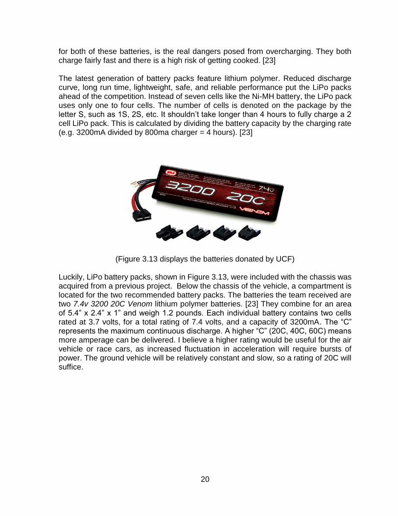
(Figure 3.13 displays the batteries donated by UCF)
Luckily, LiPo battery packs, shown in Figure 3.13, were included with the chassis was acquired from a previous project. Below the chassis of the vehicle, a compartment is located for the two recommended battery packs. The batteries the team received are two 7.4v 3200 20C Venom lithium polymer batteries. [23] They combine for an area of 5.4” x 2.4” x 1” and weigh 1.2 pounds. Each individual battery contains two cells rated at 3.7 volts, for a total rating of 7.4 volts, and a capacity of 3200mA. The “C” represents the maximum continuous discharge. A higher “C” (20C, 40C, 60C) means more amperage can be delivered. I believe a higher rating would be useful for the air vehicle or race cars, as increased fluctuation in acceleration will require bursts of power. The ground vehicle will be relatively constant and slow, so a rating of 20C will suffice.

21
How to choose a LiPo battery
10 amp 20 amp 30 amp 40 amp 50 amp 60 amp
15C 670 1330 2000 2650 3330 4000
20C 500 1000 1500 200 2500 3000
25C 400 800 1200 1600 2000 2400
30C 330 660 1000 1330 1660 2000
35C 280 570 860 1140 1400 1700
40C 250 500 750 1000 1250 1500
45C 220 440 670 880 1100 1300
50C 200 400 600 800 1000 1200
(Figure 3.14 shows the power yield for specific battery capacities) [5]
Based on this chart from RCPOWERS seen in Figure 3.14, using the 20C battery at 3200mA, will power at most a 60amp motor. This will yield plenty of power for the selected motors. Voltage and Amperage in relation to RPM can be found in the section on Motors. [5] Previously, motors on either side were wired to their respective left or right side battery. This helps with calibration, as the two motors on either side can be considered as one entity as far as motor control and power. However, for more consistency, the pros and cons of combining both batteries to a single output will be discussed in design. Store bought speed controllers feature an integrated cutoff. This shuts down the motor when LiPo batteries go below their set voltage, to protect the battery. In this case, going below 3v per cell or 6v total could permanently damage the cells. A safeguard for this is an external LiPo low voltage alarm. Unfortunately these are difficult to come by, and only the newest battery packs have specified internal cutoffs. As the motor controllers are being designed, the low voltage detector pictured in Figure 3.15 as an important defense during prototyping.

22
(Figure 3.15 shows a lipo low voltage detector)
3.2.5.2. Battery Maintenance
To sustain the performance of the LiPo, careful maintenance is required. Although not mandatory, most sources recommend “balancing” the battery pack after each charge. This ensures that all internal cells are at the same nominal voltage of 3.7V ideally. This also prevents overcharging and damage, which would occur at the maximum voltage of 4.2V per cell. To give an idea of how precise balancing should be, a difference of 30-50mV between cells is generally acceptable. Balancing the internal LiPo cells is easy with the purchase of a balancing charger. Usually, newer battery packs have an extra lead that is used for this purpose. A Li-Po voltage checker can also be used to display individual voltages for each cell. The SkyRC IMAX B6AC [38], does both and is top grade for up to 6 cells, although it costs about $50. Luckily this will be compatible for both the ground vehicle and aerial vehicle LiPo batteries, which will be discussed in the coming sections (3.3.7). Having a snug connection such as a male dean’s connector is also worth the few dollars after investing in a top charger and battery pack. Despite the risk and care that should be taken with all batteries, LiPo battery packs will be the most reliable for this project. After use, they should be fully charged stored away from the system in specific LiPo battery bags.

23
3.2.5.3. Power Distribution
Both 7.4V 20A batteries need to be evenly distributed among the ground vehicle system. A power distribution board or power distribution harness are both applicable. The option of having a board includes a physical board with numerous outputs and clear, modifiable connections. Its principle benefit is that it is meant to be simple to solder and desolder connections. Ground points are already soldered to negative component connections. The board also does not take up much space, usually a few square millimeters. However, being square in shape creates outputs on all edges which may yield awkward or inaccessible connections. Not to mention the area for the power supply is between the top surface and bottom surfaces of the chassis. The main advantage of a power distribution harness is that it is light and flexible. In fact, it’s practically waterproof with no exposed solder joints or wiring. However, it is still bulky and can actually get tangled or confusing if wires are left unused. Although both would get the job done, this situation calls for something more efficient.
A power distribution block (terminal block) is a space-efficient hybrid of the board and harness. It is an insulated block that is equivalent to the size of half a marker, with all inputs and outputs flowing one way. Connections are made by a screw tightened onto bare wire. Since wires have already been attained and the size is optimal, the terminal block will be utilized to distribute power to the ground vehicle systems.
3.2.5.4. Battery Eliminator Circuits
Many components of the ground vehicle require both a consistent and unique power supply. For example, referring to the motor controller that is being designed, an input of 14V is ample to power the chip and the DC motors. However, the required embedded processor is a low power system with a voltage range of only 1.8V-3.6V. As opposed to using a separate battery pack, voltage regulators (Or battery eliminator circuits, hence the nickname), will be implemented to power the various requirements of each component. Battery eliminator circuits work by releasing heat, burning up excess voltage to deliver the desired output. This lessens weight, frees up space, and takes away a battery that needs to be charged. Alternatively, a couple of AA batteries could power these components, but does take up precious space on the chassis. [7] Store bought battery eliminator circuits (BEC) are exceptionally tiny, and can be 15-100 times smaller than a battery pack. In fact, the initial purchase of a simple BEC was good enough for basic prototyping, but will need to be reviewed as it is a mere millimeters across. The size is especially relevant for the aerial vehicle, which needs to be lightweight, yet should automatically implement BEC’s in the selected flight controllers. The BEC also acts as a safeguard, in case of a dead battery, an unpowered but controlled descent can take place. [8] Before diving into the circuitry, it is good to distinguish the two types of BEC. Nowadays, most motor/speed controllers have internal or external BEC’s built in. An internal or 5V linear BEC is low cost and will suffice for low voltages. An external

24
switching BEC is recommended for higher voltages, to run cooler and efficiently, as shown in Figure 3.17. BEC Voltage: 6V BEC Load: 3A
Battery Voltage
Linear BEC Switching BEC
Battery Current
Wasted Power
Efficiency Battery Current
Wasted Power
Efficiency
2s lipo (7.4v) 3A 4.2W 81.0% 2.797A 2.7W 85%
3s lipo (11.1v)
3A 15.3W 54.0% 1.865A 2.7W 85%
4s lipo (14.8v)
3A 26.4W 44.4% 1.399A 2.7W 85%
5s lipo (18.5v)
3A 37.5W 32.0% 1.119A 2.7W 85%
6s lipo (22.2v)
3A 48.6W 27.0% .954A 2.7W 85%
(Figure 3.17 shows the efficiency of various linear BECs versus switching BECs) [9] With a low cell battery pack such as the (2s lipo 7.4V), there is little heat wasted due to the proximity between main battery voltage and BEC output voltage, which is usually 5 or 6 volts. As illustrated in the table above, when number of cells or load current increase, efficiency decreases drastically. Comparatively, the switching BEC is superior when it comes to capability. It actually draws less current as the cell count goes up. This would render a slight improvement in run time for the ground vehicle. However, a 2 cell battery would be in the zone for simple linear battery eliminator circuits. Since the motor controllers can handle an input up to 36V, the 14.8V supply from the batteries and terminal block will be well within the acceptable range. The motor controllers will supply and control ample power to each of the four DC motors. Back to the 14.8V output terminal block, a battery eliminator circuit will be required to step down the voltage to 5V. This will supply power to the ground station computer (Raspberry Pi) and Ultrasonic sensors. Then continuing from the new 5V power line, a further step down to around 3V will be required for the low-power MSP430G2553 embedded processor. An outline of this setup can be seen in Figure 3.18. A concern of BECs in high power systems is electromagnetic interference or noise (EMI) interfering with receiver electronics. However, the selected a linear BEC for the ground vehicle, which also correctly suggests an overall low power system. Although less efficient with power, almost no high frequency switching occurs in the linear BEC and it’s suitable for this simple circuit’s needs. If a more efficient external switching

25
BEC were to be used for the aerial vehicle, this risk could be mitigated with a ferrite ring on the power output leads.
(Figure 3.18 shows an outline of the power supplies)
3.3. Aerial Vehicle
3.3.1. Frame
3.3.1.1. Type
The first division in choice of aerial vehicle is between a plane style vehicle, and a multicopter. The plane style will provide a significantly more efficient flight in terms of battery power due to its ability to maintain flight using lift created by well-designed wings. Conversely, a multicopter must generate constant lift through each of its motors causing relatively short flight times compared to a plane. The aerial vehicle will be required to take photos and navigate based on analysis of this image. A benefit of a multicopter is its ability to hold its position in space. The image analysis required to control a plane in real time would need to be significantly faster than the time required for a multicopter since a multicopter can hover in place while calculations are completed. A multicopter’s hovering capabilities also makes step-by-step control from a ground control station significantly simpler than the process required by a plane which would need to circle a location between steps instead of the simpler solution of hovering. This differentiating also makes the timing of image capture easier with a multicopter as hovering above an object would eliminate the need for any significant timing. For the purposes of this project, the simplicity provided by a multicopter design outweighs the battery efficiency of a plane design making a multicopter the ideal choice. The second division in choice of aerial vehicle is the number of motors/propellers used for propulsion. The most common styles include the tricopter, quadcopter,

26
hexacopter, and various y-configurations. The tri-copter consists of three motors at three mounting points. This style is theoretically cheaper than the other styles due to minimized hardware. The odd number of motors will create a gyroscopic effect that causes the copter to rotate requiring one of the motor’s angle to be adjustable to counteract the unwanted rotation. A servo motor can be used to control this angle, but it will add more complexity to the autopilot programming. With only three motors, there are no possible redundancies to save the copter in event of a motor or vital failure. A quadcopter is the similar to a tricopter but with four motors on four mounting points. The symmetry inherent in an even number of motors, along with alternating clockwise and counterclockwise propellers, naturally counteract the gyroscopic effect that adds complexity to the tricopter design. Just as with tricopter, a quadcopter does not have any redundancies in case of failure of any vital components. The use of four motors will allow a quadcopter to lift a heavier load than a tricopter. Hexacopters use six motors on six mounting points. Similar to quadcopters, the symmetry of the copter naturally counteracts the gyroscopic effect caused by the propellers. Depending on the specific design of a hexacopter, the extra motors can act as a redundancy in case of failure of one of the motors; this could make the difference between an emergency landing and a crash. The use of six motors allows a hexacopter to carry a significantly heavier load than a quadcopter. Autopilot programming for a hexacopter is more complicated than that of a quadcopter, therefore a more sophisticated flight controller could be required. Two extra motors and two extra electronic speed controllers will also significantly alter the price of the copter. Y-configurations use the same shapes as the previously mentioned designs, but two motors are mounted coaxially on each mounting point. These designs will provide the greatest redundancy possible and greatest gyroscopic stability. They will allow for heavier loads, but the efficiency is reduced due to the motors arrangement. These designs are significantly more expensive due to redundant hardware. For the purposes of this project, the balance of simplicity, stability, economic efficiency; the quadcopter design is the best choice.
3.3.1.2. Configuration
The two most common quadcopter designs are the “X” and “H” designs which are shaped like the letters that represent them. The “H” design, seen in Figure 3.19, uses an oblong body with four arms extending perpendicular to the long axis. The body can be fitted to carry larger payloads, but the added weight will increase the required power. The “X” design, seen in Figure 3.19, consists of four arms extending from a center containing most of the hardware, with motor mounts at the ends of the arms. This design does not allow as much room in center, but will provide a more efficient flight. The “X” design is essentially symmetrical around the center point which will keep an even balance around the center of gravity, and equal moments of inertia around the copter. Since there will be minimal payload used for this project, the simpler “X” design is the best design.

27
(Figure 3.19 shows the “H” design (left) versus the “X” (right))
The “X” design can be configured with the arms at various angles. For symmetry and simplicity, each arm will be positioned at right angles relative to each other. The arms can be positioned in the both an “x” configuration or a “+” configuration, both seen in Figure 3.20, which are offset by a total 45 degrees relative to the flight sensors. One of these may be preferable in order to provide a clear camera view without the obstruction of propellers. For the purposes of this project, the camera will only need to view directly downward making the choice of “x” or “+” arbitrary. Hobbyists generally use the “x” positioning so this will be used for the project.
(Figure 3.20 shows the “H” design (left) versus the “X” (right))
3.3.1.3. Sizes
Symmetrical, “X” designed quadcopters are generally measured by diameter of the circle created by the motors around the CenterPoint. This measure is referred to as the motor to motor distance. Quadcopter sizes greatly vary from nano sizes, with motor to motor distances of only centimeters, to large sizes measuring over a meter. The two main design characteristics that are affected by size are the stability and the efficiency.

28
Generally speaking, copter stability increases as the size increases. The trade-off of stability is loss of the reactivity of the controls. Due to the added weight and longer radius, larger quadcopters will have greater moments of inertia. A large moment of inertia is not necessarily a negative feature because over sensitive controls can be difficult for an experience pilot to use, much less first time pilots. This can mostly be compensated for with the proper selection of motors and propellers. The quadcopter for this project will be required to remain steady enough to take clear photos at 50 meters above ground (wind conditions at this altitude will need to be taken into consideration). For the purposes, a quadcopter in the 300-500 millimeter motor to motor range will be the best fit. The relationship to between size and efficiency is complicated. Larger sizes allow for greater battery capacity, stronger motors, and larger propellers; but this comes at the price of a heavier load to constantly lift which can completely counteract the benefits of the upgraded equipment. Flying style is also an important factor to consider; a steady, hovering style would favor a larger design, while quick maneuvering would quickly drain the battery of an equivalent quadcopter. This project will mostly consist of the first flying style making a slightly larger quadcopter the best fit.
3.3.1.4. Materials
Quadcopters can be made from a wide variety of materials; wood, aluminum, carbon fiber, and glass fiber are the most common. Wood is the cheapest, and lightest material. It is also naturally dampens the vibrations of the quadcopter. The downfall of using wood for the frame of a quadcopter is the lack of durability. Relatively minor crashes can render the frame completely useless. For a first time pilot, minor crashes are expected, especially while developing the quadcopter. Aluminum is the most durable material. It is moderate price, but slightly heavier than the rest. Aluminum moderately dampens vibrations. Carbon fiber is light and extremely stiff and durable. It will not dampen any vibrations, and it is more expensive than the other materials. Often, carbon fiber allows for a PCB power distribution board to be integrated into the center plate of the frame. This will be beneficial in simplifying the wiring of the power systems. Glass fiber is notably similar to carbon fiber. It is almost as light as carbon fiber. Glass fiber is not quite as strong as carbon fiber, but significantly stronger than wood. It is also not as rigid as carbon fiber allowing the material to naturally dampen vibrations. Similarly, a PCB power distribution board is often integrated into the center plate. The most important distinction is that glass fiber is significantly less expensive than carbon fiber. The most important factor is durability. Wood cannot be used due to the catastrophic results of a minor crash. The next factor to be considered is the weight of quadcopter. A completely aluminum frame would drastically reduce the flight time of the quadcopter due to the added weight making aluminum a bad choice for the project. Overall, glass fiber would be a better choice than carbon fiber due to the significant price difference, and its ability to dampen vibrations to allow for the best possible quality images. A simplified comparison of materials can be seen in Figure 3.21.

29
Important Factors
Wood Aluminum Carbon Fiber Glass Fiber
Durability
Weight
Vibrations
Price
(Figure 3.21 show a comparison of materials)
3.3.1.5. Frame Options
Frames can be created from scratch, from sourced parts and assembled, or bought as a whole kit. Fabricating a frame would be a difficult task requiring extra tools and time as well as prior knowledge of construction techniques. A pre-assembled frame would be the simplest option. The DJI Flamewheel [29] is a quadcopter kit that comes in a 330 millimeter (F330) and 450 millimeter (F450) sizes. They are both light and durable kit that come ready to assemble. Inexpensive third party recreations of similar quality are also available. The Turnigy Talon [30] is a 550 millimeter frame with similar qualities to the Flamewheel; both are similar weight. The Talon is larger in size and made out of carbon fiber, but it has a smaller centerplate and is more expensive than the Flamewheel. Sourcing two centerplates, four arms, landing gear, and the required mounting hardware becomes more expensive and complex than simply buying a frame kit. The Flamewheel F450, which is pictured in Figure 3.22, will be the best option for this project. The larger size will allow it to be more efficient than the F330, and the inexpensive options make it a better value than the Talon or sourcing individual parts.

30
(Figure 3.22 shows the frame for the drone)
3.3.2. Flight Controller
3.3.2.1. Autopilot
The flight controller’s main task will be to run the autopilot. Though maneuverability and stability is important, the main focus of this project will be autonomous control. It will need to communicate wirelessly with the ground vehicle while maintaining automatically maintaining flight. This included taking inputs from sensors and altering motion by sending pulse width modulation signal to the electronic speed controllers. For these purposes, there will need the need to be able to extensively work with the software to program autonomous control. The autopilot will need to be open source.
3.3.2.2. Flight Sensors
The flight controller will need to constantly know the exact position and inertia of the quadcopter. This will require an inertial measurement unit. This will included a gyroscope and an accelerometer. For further precision, a magnetometer will be beneficial but not required. Another important positioning device that will be required is an altimeter. In order to implement autonomous missions, the flight controller will also need the ability to read its position from a global positioning unit. The chosen flight controller will need to be able to take each of these measurements on its own or be able to read these measurements from an external module.

31
3.3.2.3. I/O
This project will require autonomous inputs and outputs to maneuver complete the mission. For safety purposes, manual override must always be an option. All flight controllers have a receiver input. Furthermore, the flight controller must be able to receive control inputs from the ground vehicle as means of autonomous control as well as send flight data to the ground vehicle to assist with image processing. This will require a telemetry module port in the flight controller.
3.3.2.4. Options
The ArduPilot program an open source autopilot system, built with a large support base from the hobby community. 3D Robotics designs open source flight controllers that are designed to run the ArduPilot firmware. These products are designed specifically with autonomous flight in mind. The two main flight controllers from 3D Robotics are the APM 2.6 [31] and the Pixhawk [32]. Both flight controllers have a built in inertial measurement unit that include a 3 axis gyroscope and a 3 axis accelerometer. Both have a gps port that can also be used to connect a magnetometer for further accuracy. Both have a built in barometer for altitude measurements. These flight controllers have built in telemetry ports that are capable of receiving autonomous control signals from the control station. These flight controllers both fit the requirement of this project. The Pixhawk is a more powerful successor to the APM 2.6. The APM 2.6 uses an ATmega2560, 8-bit, 16 MHz processor while the Pixhawk has an ARM Cortex M4F, 32-bit, 168 MHz processor. The APM 2.6 is limited by 256 KB of flash memory while the Pixhawk has 2 MB of flash memory. The APM has 3 communication ports that are capable of UART, SPI, and I2C communication while the Pixhawk has 5 of these communication ports. The Pixhawk also runs a real-time operating system that would allow for additional features such as remote access. Regardless of all of the benefits that the Pixhawk has over the APM 2.6, for these purposes, they are all unnecessary. The Pixhawk is also significantly more expensive than the APM 2.6. For these reasons, the APM 2.6 with the ArduCopter software will be used in this project.
3.3.2.5. GPS module
The APM 2.6 requires an external global positioning module. For these purposes, it would be beneficial to have a GPS module with a built in magnetometer. Since a quadcopter is being used to hone onto a point at take a picture, errors in the global positioning will not be detrimental. In order to avoid any unwanted complications, the gps should not deviate more than two meters. 3D Robotics produces a GPS/Compass module that is specifically designed to work with the APM 2.6. This module will provide global positioning as well as the magnetometer for this project. User tests have shown the gps to be consistently

32
accurate within 1 meters as well as an average deviation of only half a meter. The 3D Robotics module also includes a rechargeable backup battery that allows for warm starts of the global positioning as well as EEPROM storage that will preserve any configuration details. This product will also be beneficial since it was designed to work with the flight controller removing any hassle that could occur during setup. For this project, the 3D Robotics GPS/Compass module will be used.
3.3.3. Communication
3.3.3.1. Transmitter/Receiver
Though autonomous control is the focus of this project, a quadcopter should always have at least 4 channel control via a manual transmitter. This will include the throttle, pitch, roll and yaw control. ArduPilot features the ability to switch among various flight modes. Extra channels would allow switching among various flight modes from the transmitter, but since a control station will be used, extra channels will not be necessary. For this project a 4 channel transmitter and a 4 channel receiver will be needed. Standard remote control transmitter/receiver systems use a 2.4 GHz connection.
3.3.3.2. Telemetry
The APM 2.6 has many built in modes that either implement various flight style modes or execute autonomous modes. Pre-programmed waypoint missions can be accessed by simply using an extra channel on the receiver on a 2.4 GHz channel. Pre-programmed missions will not suffice since this project will require mission manipulation in mid-flight. The telemetry system will be the means of implementing autonomous control. This allows you to access the flight controller and execute real time commands while in flight. Standard telemetry systems in the Americas use a 915 MHz connection. The Mavlink protocol will be used to control the APM 2.6 autonomously. This will require the telemetry transmitter/receiver to communicate with the flight controller through a UART port. On the ground vehicle side, the telemetry transmitter/receiver will need a universal serial bus connection to communicate with the Raspberry Pi. A reliable telemetry connection will be required at a minimum of 50 meters. If the connection is broken, the flight controller will send the quadcopter to a set home coordinates for safety purposes. This will ensure the safety of the quadcopter, but it will restart the entire process and be detrimental to the mission. The 3D Robotics Telemetry Radio set [33] was designed specifically to work with the APM 2.6. This telemetry system is capable of UART communication on the flight controller side as well as making the universal serial bus connection required for the Raspberry Pi. This telemetry system also has a predicted reliable connection at over 400 meters. Many other telemetry systems have similar qualities, but the 3D Robotics telemetry radio has the benefit of being designed specifically to work with the APM 2.6

33
which will allow for a seamless setup without any hassle. The 3D Robotics Telemetry Radio Set will be used for this project.
3.3.4. Motors
3.3.4.1. Specifications
Quadcopters are powered by electric motors that need to be power efficient, extremely responsive, and reliable. Brushless direct current motors have a long lifetime and are extremely power efficient compared to their brushed counterpart. Brushed direct current motors are cheaper, but do not satisfy the needs of a quadcopter. For these reasons, brushless DC motors will be used for this project. Brushless motors can be divided into the categories of sensored and sensorless. Sensored motors use a sensor module to determine the position of the rotor at all times. Sensorless motors use emf generated in the motor’s wires to determine the state of the rotor and therefore determine the when to generate the driving voltages in each phase. The sensorless system was once prone to errors making sensored motors much more reliable. Technological improvement have made sensorless motors extremely reliable as well as cheaper and more efficient than the sensored option. Sensorless brushless motors will be the best option for this project. The dynamics of choosing a motor for a quadcopter is extremely complex. As a rule of thumb, hobbyists suggest using motors that can generate thrust that is twice the weight of the entire quadcopter to allow the ability of desired mobility and acceleration. According to the Flamewheel F450 specifications, the total weight is generally between 800 grams and 1600 grams. As an estimation of the maximum weight of the quadcopter for this project, the value of 1300 grams will be used. Using the rule of thumb:
2 × 1300 𝑔𝑟𝑎𝑚𝑠
4 𝑚𝑜𝑡𝑜𝑟𝑠= 650 𝑔𝑟𝑎𝑚𝑠 𝑜𝑓 𝑡ℎ𝑟𝑢𝑠𝑡 𝑝𝑒𝑟 𝑚𝑜𝑡𝑜𝑟
≈ 22.9 𝑜𝑢𝑛𝑐𝑒𝑠 𝑜𝑓 𝑡ℎ𝑟𝑢𝑠𝑡 𝑝𝑒𝑟 𝑚𝑜𝑡𝑜𝑟 This indicates the desired maximum thrust generated per motor for maneuverability purposes. It is important to note that the motors average operating point will be approximately half of this. One of the most important specifications of brushless is the Kv rating. This indicates the number of rotations per minute per volt supplied. Quadcopters of this size and weight generally use motors between 800 Kv and 1200 Kv. A lower rating will be capable of generating a stronger torque and lifting a greater weight while a higher rating is meant to operate at higher speeds and is able to generate quicker rotational bursts. For stable consistent flights, lower Kv values can be more power efficient. Since motors are one of the most important factors affecting the flight time, power efficiency is one of the deciding factors for the motors in this project. The only way to
34
accurately know how efficient a motor is, would be to test each motor. Due to time and budget restrictions, testing each motor that is being considered is not an option. A helpful resource is found in hobbyists who have personally tested various motors and compiled measurements that are useful in determining the power efficiency of the motors. These will generally be in the format of a table listing generated thrust against amperage and voltage draw (power) using various propellers. These motor data table are one of the most helpful tools available when choosing motors. The weight of the motors can affect the power efficiency. Since there are four motors, any unnecessary weight will added by a motor will be multiplied by four which can quickly add up. Two important factors that always needs to be considered is price and quality. Budget motors are available for as low as 10 dollars each, while high end motors can exceed 100 dollars each. With a minimum of 4 motors needed, the extreme price differential can be overwhelming when deciding on which motors are suitable. Though quality generally improves as price increases, these do not always correlate. User reviews and experiences will be useful to determine the quality of potential products to be chosen independent of their price.
3.3.4.2. Options
A few potential choices include the SunnySky X2208 KV1500 II Brushless Motor [34], SunnySky X2212 KV980 II Brushless Motor [35], the Suppo 2217/9 950KV Brushless Motor [36], and the AXI Gold 2217/20 Outrunner Motor [37]. The AXI motor is the most suggested and highest reviewed motor of the three. As expected with exceptional quality, this motor is sold for around 100 dollars each. A total of 400 dollars for only the motors is completely disproportionate to the budget. For this project, there are not enough benefits to this motor to justify the large price tag. Both of the SunnySky motors and the Suppo motor all cost approximately 20 dollars each. This is a much more reasonable price tag for this project. All three of the motors are similar size but vary in weight. Four SunnySky KV1500 motors weigh approximately 176 grams. Four SunnySky KV980 motors weigh approximately 224 grams. Four Suppo motors weigh approximately 280 grams. The 104 gram difference between the SunnySky KV1500 and the Suppo motors is a dramatic difference for a quadcopter that is expected to be ~1300 grams. An additional 8% of weight would significantly affect the power efficiency of the quadcopter. The difference between the SunnySky KV980 and the Suppo motors is 56 grams (~4%). These differences could be an important factor in determining the flight time of the quadcopter. Two of the motors are within a similar Kv range, while the SunnySky KV1500 is being compared to ensure that the assumption that a lower Kv value will produce a more power efficient flight is correct. They all have similar expected amperage draws (~15

35
amps maximum) and are designed to use an 11.1 volt Lipo (3s) battery supply. The use of an 11.1 volt battery supply is common for quadcopters this size; this will be taken into consideration when choosing the power supply. The SunnySky KV1500 is designed for 7 to 8 inch propellers while the other two are designed to use 8 to 10 inch propellers. All three motors are also well reviewed and liked by users. With three similar, good quality, and reasonably priced options, the motor test data from Figure 3.23, Figure 3.24, and Figure 3.25 will be the best way to decide.
(Figure 3.23 shows flight test data for the SunnySky X2208) [44]

36
(Figure 3.24 shows flight test data for the SunnySky X2212) [44]
(Figure 3.25 shows flight test data for the Suppo A2217/9) [45]

37
When analyzing this data, the focal point will be the grams of thrust per watt of power that is labeled “Power Efficiency”. A rule of thumb is that anything above a value of 7 is a good efficiency. These values need to be compared to the expected operating range of thrust from ~200 grams to ~600 grams. The first thing to note is the differences between the 1500Kv motor and the ~900Kv motors. As expected, the 1500Kv motor runs at a significantly higher RPM allowing for a higher level of maneuverability. Also as expected, the power efficiency is significantly lower. These are undesirable characteristics for this project making the lower Kv motors a better choice. The SunnySky KV980 and the Suppo motor both produce similar performance data. A closer look is required to see any differences. For the same size propellers, comparing the power efficiency at equivalent thrust values shows that the SunnySky KV980 consistently more efficient. The two main deciding points between the SunnySky KV980 and the Suppo motors are the motor weight and the power efficiently. The SunnySky X2212 KV980 II is the best motor choice for this project.
3.3.5. Propellers
3.3.5.1. Material
Quadcopter propellers are generally made out of either carbon fiber or plastic. Firstly, carbon fiber propellers are significantly more expensive than plastic; often they are twice as expensive. Generally, carbon fiber is also slightly heavier than plastic which would make them less efficient for two reasons: the total weight of the quadcopter would increase as well as the increased moment of inertia would draw more power to generate the same rotational velocity. Carbon fiber’s greatest advantage is its rigidity. Rigid propellers reduce the vibrations caused at high speeds. Its rigidity also makes it extremely resistant to wearing while plastic propellers will wear regularly. The extreme rigidity may reduce wear, but carbon fiber propellers are still susceptible to cracking when crashes occur. A simplified comparison of propeller materials can be seen below in Figure 3.26.
Price Weight Durability Vibrations
Carbon Fiber
Plastic
(Figure 3.26 shows a comparison of propeller materials)

38
Though carbon fiber is more durable than plastic, it is still susceptible to total failure in event of a crash which is much more likely for a first time pilot. The extreme price difference of plastic would likely compensate for the difference in durability. For this project, plastic propellers will be used.
3.3.5.2. Style
Multicopter propeller, while all taking the same general shape, vary between manufacturers. Many manufactures produce “slow fly” versions of their propellers. These are designed for lower rpm flights and have the potential to be more efficient than regular propellers. They are also generally slightly lighter and more fragile. Slow fly propellers are used at lower pitches than regular propellers. Most hobbyist note that the type of propeller does not affect the efficiency nearly as much as the proper size and pitch choice. For this project, slow fly propeller will be used whenever available.
3.3.5.3. Size and Pitch
Propeller size is measured as the length from end to end. Generally, at the same motor voltage, longer propellers will generate more thrust than shorter propellers but will generate more resistance. This will also cause the longer propellers to rotate slower and draw more current. This is tradeoff that needs to be carefully analyzed as this allows motor to operate at a lower voltage and still produce the same thrust; this often will result in a greater power efficiency. Propeller pitch, essentially the angle in which the propeller is tilted, is measured by the distance the propeller would travel in one revolution. This is equivalent to how far a screw will move into plank in one revolution. The flight characteristic of the propellers pitch is similar to that of the length. Generally the pitch is increased proportionally to the length. Adjustment of the pitch is useful for compensating for factors such as the low air density at high altitudes. Propellers should be selected to directly match the specific motors that are being used. This process will provide the best results using the flight data from Figure 3.24 which was used to select the motor. The tests were performed using various length x pitch combinations. The 9x5 and 10x6 sizes each produce a similar power efficiency in the expected thrust range of ~200 grams to ~600 grams. If the quadcopter end up lighter than the predicted value, the 9 inch size might be a better choice. A pitch of 6 is larger than that of most 10 inch propellers. Many hobbyist who own this motor suggest 10 inch propellers with a smaller pitch of 4.5 or 4.7 which could potentially be a better choice. A range of sizes should be tested to determine the greatest efficiency possible for the quadcopter. 10x4.7 and 10x6, and 9x5 will each be tested before deciding which will be used for the final design.

39
3.3.5.4. Options
There are many different brands of propellers available that make quality product. From the suggestions of hobbyist, APC brand propellers will be use. A 10x4.7 and a 9x4.7 slow fly propeller as well as a 10x5.5 standard drive propeller will be tested. It is important to note that two of the propellers must be designed for clockwise rotation while the other two designed for counter clockwise rotation. The reverse rotation will naturally loosen the nut holding the propeller onto the motor. It is important to use an adapter, a locking nut, or a reverse threaded shaft for the opposite rotation. For budget purposes and ease of use, nyloc locking nuts will be used.
3.3.6. Power Supply
3.3.6.1. Batteries
Radio control hobbyists use a wide range of battery types including nickel-metal hydride (Ni-MH), nickel-cadmium (Ni-Cd), lithium polymer (LiPo), and many more. The most important aspect when choosing a battery for a quadcopter is the power capacity per unit weight. While the nickel based batteries are a cheaper option than lithium based batteries, but they typically have a low capacity to weight ratio making them a better choice for ground vehicles or fixed wing aircrafts. Lithium Phosphate batteries will be the best choice for this project. The first characteristic to be analyzed is the voltage output. LiPo batteries are comprised of various configurations of cells. Each cell has a nominal voltage of 3.7 V and a maximum charge of 4.2 V. LiPo batteries that are used for quadcopters are generally aligned in series while some are also aligned in parallel. For these purposes, the batteries will not need to be in parallel. Cells in series generally range from 1 to 5 cells. For the selected motors, a voltage range of around 7 to 11 volts will provide the required thrust. For these purposes, a battery with three cells in series (denoted by 3s) which will provide a nominal voltage of 11.1 V will be needed. Next, it is important to know the discharge rating (C-rating).
𝑀𝑎𝑥𝑖𝑚𝑢𝑚 𝐷𝑖𝑠𝑐ℎ𝑎𝑟𝑔𝑒 𝑅𝑎𝑡𝑒 = (𝐶𝑎𝑝𝑎𝑐𝑖𝑡𝑦) ∗ (𝐶 − 𝑟𝑎𝑡𝑖𝑛𝑔) In order to estimate the maximum discharge rate a predicted maximum rating will be used of the Electronic Speed controllers which will set to be 20 A. This will make the maximum required discharge rate 80 A. This estimate is, by far, liberal enough to account for the current draw of all other components. From this analysis, the required C-ratings are shown in Figure 3.27 below.

40
Battery Capacity (mAh) Maximum Discharge Rate (A) C-rating (1/h)
2200 80 36
3000 80 27
4000 80 20
5000 80 16
(Figure 3.27 shows the required C rating for various capacities) It is important to note that a battery is specified to have a constant C-rating as well as a peak C-rating which should not exceed 10 seconds of discharge at that rate. The next characteristic to analyze is the capacity. Quadcopter LiPo batteries generally range from 1000 mAh to 6000 mAh. While it may seem like a good idea to choose the largest capacity for the longest flight time, often the added weight will increase the power draw enough to lower the flight time. This relationship curve is often difficult to predict without solid test data. For this analysis, I will be using Turnigy Lipo packs with the corresponding C-Ratings calculated in Figure 3.27 above. For analysis purposes, the predicted maximum value of the quadcopter excluding the battery will be around 900 grams. Also, the flight analysis for 9x5 propellers will be used.

41
Battery Capacity (Ah)
Battery Weight (g)
Total Weight (g)
Motor Thrust (g)
Amperage Draw (A) (4motors)
Battery Life (minutes)
Turnigy 2.2Ah 3s 35C
2.2 199 1099 274.75 15.9221 8.29036370
Turnigy 3Ah 3s 30C
3 269 1169 292.25 16.7551 10.7429976
Turnigy 4Ah 3s 20C
4 337 1237 309.25 17.5643 13.6640799
Turnigy 5Ah 3s 20C
5 412 1312 328 18.4568 16.2541719
2 parallel Turnigy 5Ah 3s 20C
10 824 1724 431 23.3596 25.6853713
(Figure 3.28 shows predicted battery life estimates)
(Figure 3.29 shows predicted battery life estimates graphically)
According to the calculations from Figure 3.28, flight time steadily increases as the battery capacity increases which can easily be seen in Figure 3.29. It also appears to be effective to use two batteries in parallel. These results will need to be verified.

42
Firstly, a 2200 mAh and a 5000 mAh should be directly compared to ensure a significant increase in flight time. After this is confirmed, two parallel batteries should be tested to confirm that it will significantly increase the flight time. Using actual flight data, an accurate analysis can be performed and the proper setup can be chosen for desired performance.
3.3.6.2. Distribution
The 11.1 V power supply needs to be evenly distributed. This can be done with a power distribution board or a power distribution harness. The option of a board consists of a positive conductive plate to which component connections are soldered and ground points to which negative component connections are soldered directly. The board is beneficial in the fact that it is easy to connect and disconnect different components. This can also make for a neater, easier to manage setup. The wiring harness option consists of interconnected wires that directly make each required connection. The harness will generally be lighter than an equivalent board and have very few points in which any wiring is exposed. The downside is that it is much more difficult to connect and disconnect components and it can become difficult to manage a tangle of wires. The Flamewheel F450 frame comes with a built in power distribution board. This option will be used rather than a power distribution harness. It will be much easier to manage each connection and the final result will be a neat product.
3.3.6.3. Battery Eliminator Circuits
The motors will run off of the 11.1 V power source from the power distribution board. This power connection will be made through the electronic speed controllers. The flight controller and the receiver need a 5 V power source as well as the camera transmitter. A separate 5 V battery supply could be used to power these components, but a better solution is to use battery eliminator circuits to power these components. These simple circuits are often included in the electronic speed controller circuitry. If they are not included, a battery eliminator circuit simply needs to be attached to the 11.1 V supply on the power distribution board, and the 5 V output can be attached to the components that require it. In high power systems, voltage noise can cause fluctuations and errors between the receiver and the electronic speed controllers. In this case, and opto electronic speed controller can be used paired with a separate battery source for the receiver. The opto connection in these speed controllers uses a light emitting diode and a light detector to create an optical path that isolates the electrical connection. In this setup, a separate battery is required for the receiver so that it is electrically isolated. This means that a battery eliminator cannot be used. For these purposes, there should be a low enough noise level that an opto electronic speed controllers will not be necessary. In this case, battery eliminator circuits can still be used to power the 5 V components.

43
3.3.6.4. Battery Maintenance and Safety
Lipo batteries are sensitive and require precise charging. Each cell of a battery has a nominal voltage of 3.7 V. When charging a battery, it extremely important to ensure that a cell does not exceed the maximum voltage of 4.2 V. Above the maximum voltage, the cells become unstable which will damage the battery as well as create a potential for the battery to become dangerous. Lithium based batteries have the potential to explode and catch fire. Lithium fires are extremely dangerous due to the self-sustaining nature of metal fires. For this reason, Lipo batteries should always be charged and stored in bags that are specifically designed to hold Lipo batteries. When using Lipo batteries, any batteries that are in series that are not exactly the same voltage can be dangerous. Since Lipo batteries are made with multiple cells in series, it is vitally important to ensure that each cell is also at the exactly same voltage. This will require a battery balancer that will ensure the cells are at safe voltages. The SkyRC IMAX B6AC balancing charger [38] is an economical choice that also provides every feature that is needed. This charger allows for use from an ac power source. It will also charge and balance 3s Lipo batteries. The Turnigy 5000mAh 3s 20C batteries have a 2C charge rating. This will allow the batteries to be charged with up to 10 amps. The IMAX charger allows for up to 6 amps. This will fully charge a fully drained battery in around 50 minutes which will be acceptable for this project. The SkyRC IMAX B6AC will be the best choice for a Lipo battery charger. The minimum voltage of each cell is 3.0 V. If a cell is discharged close to the minimum voltage, permanent damage can occur reducing the longevity of the battery. Damage will begin to occur when the battery is around 3.2 V. To prevent over discharging batteries while in flight, it is pertinent to use a battery voltage alarm that will automatically sound at a given low voltage threshold.
3.3.7. Electronic Speed Controllers
3.3.7.1. Hardware Design
The electronic speed controller is the integral device that converts pulse width modulated signals from the flight controller into precise control of the brushless motor. Most commercial electronic speed controllers use similar hardware formats with various changes make them unique. Designing the hardware for the speed controllers will allow for control of exactly what is wanted from the controller. Firstly, electronic speed controller will be able to be tuned to the exact voltage and amperage requirement that are needed for this specific quadcopter. This as well as the PCB layout design will allow the group to make each speed controller as light as possible allowing the quadcopters flight time to be maximized.

44
The speed controller uses three identical phases to control the three phases of the motors. Each phase will use a half bridge mosfet design to drive the phase with a positive or negative voltage. Two NMOS devices should be used rather than using an NMOS and PMOS pairing for a couple of reasons. Making both devices an NMOS would create symmetry in the electrical characteristics of the mosfets. NMOS devices are also more efficient that the PMOS which could cause problems with excess heat. The use of two NMOS devices in a half bridge circuit would require a bootstrap circuit to drive the negative voltage. A NPN transistor or a high/low side driver could be used to drive the half bridge. The high/low side driver would be a more accurate and high quality option to drive the half bridge circuits. When using a sensorless brushless motor, which was chosen to be used in this project, while one phase is driven positive and another phase driven negative, the third phase is used to control the timing of motor. Since there is no voltage applied to the coiled wires in the third phase, the rotating magnets will generate a small current in the wire. The processor will measure this signal and use it to time the next shift in phase. Filters can be used in this feedback line to remove unwanted noise thereby reducing or removing possible timing errors. This will provide the freedom to select a desired processor and use a selected open source firmware to run the speed controller. A voltage regulator will be needed to supply the processor as well as battery eliminator circuits can be design to supply other parts of the quadcopter. A charge pump can be used to provide a clean power supply to the high/low side drivers. After a rough estimate of the desired components to create a single prototype as well as four final designs including PCB boards, the cost would be significantly more than that of commercial electronic speed controllers. Also taking into account the time that would be required to fine tune all of the resistance and capacitance values of the prototype, this time would be disproportionate to the time required for the project as a whole. It is decided that selecting a commercial electronic speed controller that best fits these needs will be the best choice for the project.
3.3.7.2. Hardware
The first specification of a brushless electronic speed controller to be considered is the voltage rating. Most speed controllers will be rated to handle a range of voltages. The batteries that will be used for this quadcopter will be 11.1 volts Lipo (3S). The selected speed controllers will need to be rated for 11.1 volts. The next specification to be considered is the amperage rating. As a rule of thumb, a speed controller should be rated to handle at least 120% the maximum amperage draw of the motors. The maximum amperage is generated when the greatest resistance is applied. In the motor performance data seen in Figure 3.24, the greatest resistance is applied with the 11x7 sized propellers. This propeller will generate more

45
amperage than any of the propellers that will be potentially used for this project. In this extreme case, the maximum amperage generated is 14.5 amps. This would require a speed controller that is rated greater than 17.4 amps. An 18 to 20 amp electronic speed controller will be the best choice for this project. A speed controller that is rated for anything greater than 20 amps can be used, but the added weight of the additional hardware would need to be taken into account. Many electronic speed controllers are designed with build in battery eliminator circuits. This is used to power the speed controller’s processor as well as the flight controller, receiver, and any other components that run on 5 volts. Often, a battery eliminator circuit on each of the four electronic speed controllers is more than needed as this can be accomplished with one separated circuit. The added weight is usually small enough that it will have no significant effect on the quadcopter’s flight time making the convenience of these built in circuits a bonus.
3.3.7.3. Firmware
Most commercially sold electronic speed controllers use extremely similar hardware designs. Many open source firmwares have been written that perform better than the firmware that is written on the commercial speed controllers. Many hobbyists regard SimonK firmware as the most reliable and most responsive firmware available. It has become a fairly common practice to flash this firmware onto various speed controllers. This code has been thoroughly tested on a large number of controllers and there is a large community of support. The best choice for this project would be a speed controller that has a hardware layout that is compatible with SimonK firmware, and to reflash the controller.
3.3.7.4. Options
A few options for electronic speed controllers that fit these requirements are the Mystery 20A [39], the Turnigy Plush 18A [40], and the Afro 20A [41]. Each speed controller are approximately the same weight at 20 grams, 19 grams, and 22.8 grams respectively. All three are designed to be used with an 11.1 volt Lipo battery system. They all are rated to support the estimated maximum amperage draw. Each speed controller also comes with built in battery eliminator circuit. According to the hardware specs of these speed controller, they all appear to be nearly equivalent, as well as they are approximately the same price. Each of these speed controllers are compatible with SimonK firmware. The Afro 20A speed controller stands out because it was designed in part by the writer of the SimonK firmware and the firmware is already programmed on the speed controller. Reflashing the firmware onto either of the other speed controllers leaves room for errors to be made causing time to be wasted troubleshooting the problems. The simplest and most efficient choice is to use the Afro 20A electronic speed controller for this project.

46
3.4. Intercommunication
3.4.1. Ground Vehicle - Aerial Vehicle
Communication between the GSC and the overhead drone will need to occur in two separate channels, one to transmit and receive telemetry data from the flight controller onboard the drone and another to transmit the data from the onboard camera module.
3.4.1.1. Telemetry Commands
Since communication between ground stations such as a computer and an overhead drone such as the selected quadcopter is a common problem shared by nearly every operator of such drones the technology is relatively well developed and researched. With the 3DR V2 Radio as the medium, a 300m range of the drone from the GSC can be achieved without any adjustment of the hardware. [24] These radio systems are easy to install on the computer end as well as they utilize USB connections, or can be connected to a computer such as the RPI through the tx/rx/power/gnd GPIO pins directly on the board as seen in Figure 3.30.
(Figure 3.30 shows the 3DR module connected to the ArduPilot module.)
In the image above the connection of the 3DR V1 Radio module to a 2.5 ArduPilot board can be seen, which will be similar to the board that it is planned use in the future. The V2 radio is essentially the same, only it has a connection option for USB as well as the bare I/O pins so that a computer can be more easily connected to the system. [25]

47
Connection to the computer is similarly simple as you can easily connect the radio into any of the USB ports and the device will be recognized and drivers installed for immediate use. The computer can also be connected to the radio module using the tx/rx pins on the GPIO pin assembly. Both of these configurations can be seen in Figure 3.31 below. [24]
(Figure 3.31 shows the necessary GPIO connections for the 3DR radio to RPI) [25]
After this module is connected to the GSC, it will all be configured and interfaced with the control program that will issue commands to the overhead drone. The module should be able to be instantly recognized by the computer operating system and from there set up should be simple and communication can begin. The Frequency band at which these radios communicate is set at 915 MHz for the United States, however if it is decided decide to use a different module it could be a 2.4 GHz frequency that gets used. [25]
3.4.1.2. Image Feed
Image feed is similar in the ease at which the modules can be collected and assembled as well as interfaced with the selected components. This time there are a few things to be kept in mind when selecting the components. Firstly, the frequency that the control radio communicates on needs to be kept in mind. If this is ignored and a transmission system that broadcasts on the same frequency as the control radio is selected, it could drop the quadcopter out of the sky or prevent it from taking off in the first place. Not only this, but there are specific standards in place by the FCC that limit the transmission strength and powers of certain frequencies which could lead the group to trouble with the law. For this reason, it was specified that the video feed to be transmitting on the 5.8GHz. Secondly, the transmitter system must be powerful

48
enough to broadcast high resolution video over distances of up to 200m to get a good area of coverage to search for the maze. This leads to a greater demand for higher quality batteries for this system as well so as to not have a cut out of service in the middle of testing. For these requirements, it was decided to go with a camera system like the SPMVA1100 Camera and Video Transmitter system as seen in Figure 3.32. The benefits of this system are that it weighs merely 4.5 g total excluding the battery, runs off a 3.3 - 4.2 V battery power supply, has a 115° field of view, and has been reported to have a range of around 100m to 200m without any modification to the system. [26] Anecdotal evidence of the system complains of difficulty transitioning between a ground viewscape and a sky/horizon viewscape, though this shouldn’t be a problem for the systems as the camera will be mounted facing the ground at all times. Users of the system also complain of short operating times on smaller or cheaper battery systems as well as shorter ranges once those batteries start to run low. To counteract this it is recommended to use fresh batteries and to use a robust enough quadcopter to carry an increased battery load.
(Figure 3.32 shows the SPMVA1100 camera module) [26]
To catch the video that this camera transmitter casts out it will be necessary to hook up a receiver directly to the GSC that will allow the computer to watch a stream and take stills at will. For this system to be feasible it has the constraints that it must be lightweight and able to connect to the GSC preferably via a USB connection so as to not crowd out the GPIO pins that are sure to be use by this point. Unfortunately there are not many systems designed for the 5.8GHz transmission range that can be suitably streams to a computer as most hobbyists stream directly to a receiver tied to a screen or headset to reduce picture latency. In this case, the picture latency up until the 2s response time range does not make a significant difference which will expand the options available to the group. Taking all these constraints into account a suitable receiver system has been selected. A system like the Modular USB for Rx, as seen in Figure 3.33, would work well for this

49
system, it has a USB interface and a modular build design so multiple different wireless chips can be used in case it is required to switch streaming channels due to interference. [27] It is also compact and would easily fit on the ground vehicle assembly with what has been designed so far. The downsides to this system are as with the small form factor there is a chance of a shorter range which would limit the effective area of effect that the overhead drone could operate in. There is also very little documentation with this system which is concerning as the GSC has the potential to be voltage sensitive and the wrong drop in current could reset the whole system.
(Figure 3.X shows the 3DR radio module chosen for this project.)
3.4.2. Image Processing to Ground Vehicle Control
The communication between the image processing and the ground vehicle controller, the Msp430 embedded processor, is comparatively simple when compared to the communication requirements for the rest of the project. The MSP430 chipset allows communication via UART pins and allows for simple ASCII characters to be passed between a terminal on the GSC side and the UART input buffer on the embedded processor side. Because of these characteristics, the most efficient way to transmit the turn instructions is as a single string where every char represents a different turn profile. The turn profiles, as shown in section 3.5.5, will need to be encoded to different chars or numbers. Since there are only 6 turns necessary in the reduced turn set, the turns can be simply encoded as the numbers 0-5 with each number representing a different profile that will be seen by the sensors as it passes through the maze. The maze will

50
be broken up into sprints that consist of a straight line until the required turn and every turn along that path. So if the maze has two four-way intersections before needing to make a left turn, the characters ‘6’ ‘6’ ‘0’ would be transmitted to the embedded processor via UART. An example of this process can be seen in Figure 3.34 below.
(Figure 3.34 shows uart communication to the terminal from the embedded
processor) These are not the only commands that will be sent to the msp430 however as there are several other commands that need to be taken into account if the ground vehicle is to behave appropriately. There need to be a halt command and a move command that starts the vehicle at the beginning of the maze after the overhead drone takes an appropriate picture and stops the vehicle after it has completed the maze.
3.5. Image Processing and Implementation
3.5.1. Edge Detection
Edge detection is considered as a collection of mathematical and logical algorithms and programs which aim to detect the edges on a digital image. Edge detection detect the edges by identifying the sharp changes and find the jumps in brightness. There are many different edge detection algorithms such as Sobel, Canny, Robert, Prewitt, and LoG (Laplacian of Gaussian), but what is used for this project is Canny Edge Detector. Edge detection is an image processing technique that will be used to detect the edges of maze in this project. Maze walls and background are colored black and white

51
respectively, so they can be distinguished from each other easily. Although there are many advanced edge detectors available, the simplest and the most efficient ones are Sobel and Canny. Sobel and Canny edge detection algorithms are both using a mathematical process called convolution. Convolution is a process of multiplying and summing matrices together. Sobel detection calculates the gradient magnitude of an image by using a 3*3 filter. Where "gradient magnitude" is, for each a pixel, a number giving the greatest rate of change in light intensity in the direction where intensity is changing fastest. Canny edge detection goes one step beyond. It first reduces the noise by using a low pass filter and then uses the Sobel filter, and finally using non-maximum suppression to pick the best pixel for the edge among all its neighbors. The tradeoff of Canny’s accuracy is a little more processing overhead which is negligible. Sample of outputs for both Sobel and Canny edge detectors can be seen in Figure 3.35.
(Figure 3.35 Shows the Edge Detection Steps)

52
As it can be seen on the above pictures Sobel either captures some parts that are not edges or losses the edges whereas Canny detect the edges perfectly. Although there is not much noise on a black and white colored maze, Canny is being used for the purpose of accuracy.
3.5.2. Maze Detection
In computer everything can be classified as an object. Object detection and
recognition is a process for identifying a specific object in a digital image. In computer
and robot vision world, finding and classifying objects efficiently is one of the most
challenging areas. Finding a specific object in an image requires an efficient way of
machine learning and image processing. Although computer vision programs and
algorithms have improved significantly, limitation to a specific class of object is still a
problem. That means a program works only for specific class of objects such as faces
or car tags, and cannot work to detect different things.
For the Maze Zone Drone project, maze is treated as an object in a digital image. In order to find the maze in a specific area, drone needs to fly over the given area, take a clear image and send it over the wireless channel to the Raspberry PI 2, which is mounted on the ground vehicle. Then image processing program will decide if the maze is on that picture and send a proper response back to the drone. This process can be seen in Figure 3.36.
(Figure 3.36 illustrates drone maze detection and communication with the vehicle)
Finding the maze in the given area is one the most challenging part of this design. There are multiple approaches to find an object using image processing, yet not all of those are applicable for the Maze Zone Drone project due to the constraints. Since timing is very important image processing techniques that require a high amount of process and time are not suitable.

53
One of the suggested methods to find the maze was to make a grid of the given area and then program the quadcopter to fly and take a picture of each square. This method is pictured in Figure 3.37. In this method quadcopter needs to be equipped with a GPS kit to get the coordinates and scan the given field. The problem with this method is the amount of time it takes to scan the area. Due to restricted fly time of the quadcopter this method is not applicable.
(Figure 3.37 illustrates the drone grid approach)
Another suggested method was to fly the quadcopter high enough that it can take a clear picture of the whole field and send the image to the ground vehicle for the process part. The requirements for this method is stabilizing the drone on a high altitude, taking a clear picture, and having a sophisticated image processor that can distinguish between the other objects and the actual maze. There are two suggested techniques to approach this method. First one is utilizing an object detector that can be trained for a specific object in this case a maze. The second method is by color coding the maze and using an image processing technique called color detection.
3.5.2.1. Maze Detection by Utilizing AdaBoost Face Detector
Usually there is a tradeoff between the accuracy and speed in object detectors. Among many object detection methods such as example-based learning, neural networks, and support vector machines, the most famous algorithms that is used for specifically face recognition is AdaBoost. It is famous for its 95% accuracy while reporting only 1% false positives. The way AdaBoost works is by training the classifiers or experts. In order to train the experts to detect the specific object for instance a maze, a diverse collection of different mazes and none mazes are required. Researches indicate that

54
the best result is achieved when the experts are trained with a database of 2000 positive objects, in this case mazes and 2000 negative objects. Maze detection provides many challenges using AdaBoost. One of the problems with this method is training the program with a collection of 2000 random mazes and none mazes. This by itself needs a program that can generate this collection. Generating this collection and training the experts entails a significant amount of time and process (almost about 45 minutes with an Intel Core I5 2.7 GHz). Another problem is the angle that the image is taken. In order to get the best result, digital image from the maze has to be taken with an angle less than 25 degree which is not always possible. Based on an experiment that was done by the team, the error increases by about 30 percent when the maze image is taken with an angle more than 25 degree. Although AdaBoost is an effective solution to many classes of object detection, it is not suitable for this project due to its error and hardware requirements. There are simpler approaches such as object detection by color or using the superpixels.
3.5.2.2. Real-Time Object Tracking Using OpenCV
Color can represent a great information about an object. The final suggested approach is to detect the maze is using a color detection program. There are several different methods that can be used for color detection, but the most practical one for this project is color detection using Open Source Computer Vision library or OpenCv. OpenCV is an open source library that contains more than 500 different methods and functions for a real time image processing. It can be used for motion detection, object detection, facial recognition, gesture recognition, and augmented reality. It has been used for some similar projects such as AR Drone Target Tracking. Since OpenCV can be run under Linux, Windows, OS X, iOS, and android, it can be easily installed on the Linux based Raspberry PI 2 OS which is used for this project.
Real Time Object Detecting program follows three main steps. The first step is to convert the captured image or real time video from RGB format to HSV. RGB is an additive color system that categorizes each color by amount of Red, Blue, and Green lights. It is not easy for a human eye to describe the nature of color by measuring the amount of each light. Therefore a more sophisticated color system that describes a hue shift, saturation, and value also known as HSV is being used for this project. A comparison of HSV and RGB can be seen in Figure 3.38.

55
HSV RGB
(Figure 3.38 shows RGB and HSV color systems.) [6]
The second step is to filter the colors or pixels of interest using a minimum and maximum threshold. In this step desired color will be separated from its surroundings. Last step is performing morphological operations to reduce the noise by eroding the little white spaces around the object and dilating the detected object. This process is shown in Figure 3.39.

56
Actual Object Color Filtering
Noise Reduction Object Expansion
(Figure 3.39 shows the steps to filter an object)
In the project, to detect maze on the given area, the maze will be color coded. A camera that is installed on the quadcopter captures real time video from the given area and sends the result over a Wi-Fi channel to the Raspberry PI which is mounted on the ground vehicle. Image processing program that is installed on the PI filters the maze color from its background and send the result to the program that is in charge of calculation of distance between the quadcopter and the maze. Result of this calculation will be output to the quadcopter controller. If the quadcopter is not close enough to take the final shot of the maze, controller will adjust the distance and coordinate of the quadcopter until it reaches the proper distance from the maze.
3.5.3. Maze Solving
There are many algorithms that can be utilized to solve a maze. Some are time optimized to find any solution quickly, not just the best case solution, and others are optimized to find the best case solution no matter how many iterations they have to cycle through. For this project, there are a couple of parameters that are of interest

57
that the algorithm will solve for the best case/shortest path first and secondly to solve this maze in the shortest time possible.
3.5.3.1. Dijkstra’s Algorithm
The first algorithm that will be investigating for possible use in this project will be Dijkstra’s Algorithm for path finding. This algorithm has a start node and an open set of nodes that are structured based on a weighting system that places nodes closer to the start higher in the list. As a node is visited, the connected nodes are added to the list based on their weight and the visited node is popped from the list, a node that has been already analyzed will not be re-added to the list, so there is no chance of an endless loop. The advantages to this algorithm are that when the finish node is reached, the resulting path will be the shortest due to the way each node is analyzed. The use of this this algorithm in this project is being investigated as it provides 100% accuracy for the shortest solution at a reasonable rate even though it does employ a brute force solution. For this to work the image that is generated prom the camera on the drone undergo the standard image processing by the related software, to prep it for analysis, and then as an extra step the image would need to be sectioned off into a grid system that could be used in order to traverse the maze programmatically. From there, the software to solve this maze would need to be able to analyze each grid in the image and tell what is in that grid, whether a wall, a path, or a turn. From there it could assign the value of a visitable node or an unvisitable wall or obstacle. Dijkstra’s algorithm has some issues though chiefly if there can be negative cost to movements along a path, however since there will generally never be a negative cost to move from node to node this is not a limitation to this project and as such Dijkstra’s Algorithm remains a viable option for use. There are some practical limitations to the algorithm, specifically being the analysis of the maze using the software. The program may not be able to easily define what the standard grid size should be for the maze in order to correctly and without sizing error grid the image. If the grid ends up being too large, entire turns could be ignored and a solution could never be generated, too small and the solution will take much longer than expected in the estimations.
3.5.3.2. A* Algorithm
A* algorithm is a pathfinding algorithm that is similar to Dijkstra’s algorithm as it examines nodes in roughly the same way, however it also computes the distance to the finish, which is known in this variation of algorithm and gives greater importance to paths that have a lower distance to the goal node. As the distance to finish approaches zero the A* algorithm approaches the efficiency and accuracy of Dijkstra’s algorithm, however it can find solutions that are not considered optimal or shortest by virtue of distance. Because of the weighted node preference system to search out nodes that reduce the true distance to the goal node, the A* algorithm generally runs a bit faster than Dijkstra’s Algorithm which searches nodes radially from a starting

58
point, however certain mazes could cause a shortest path in preference to a path that reduces the distance to goal. The A* algorithm would have similar limitations as Dijkstra’s algorithm with regards to image processing, as the image would have to be sectioned off into a grid that the maze conversion software would then have to analyze. As a result there is no real advantage to using the A* algorithm over Dijkstra’s algorithm in this particular project and thus can be disregarded in the final selection process.
3.5.3.3. Morphological Transformation
Another interesting way of solving the maze is by using the power of image
processing. By using openCV’s powerful library, a maze can be solved in via a simple
morphological transformation. The only problem with this method is that it works only
with a perfect maze, or a perfect maze is the one that has only one solution. That
means only one start, one end and path to get from start to end and it does not work
for any circular path or open areas. These limitations reduce the overall design of the
mazes that can be used in tests like this, such that a maze of grids that has many
multitudes of solutions would not be appropriate to solve, however the benefits of the
solving algorithm are many. One benefit over the previously listed algorithms is the
integration with OpenCV, rather than having to reinvent the wheel so to speak with a
piece of software that is specifically designed to work with these very limited
constraints, the project can use a system that is already tried and tested by hundreds
of other maze solving enthusiasts. Besides this the program can also be used with
very little overhead and does not require the analysis of many nodes, but rather follows
the singular path edge to the end of the maze. This simplification of the running
process leaves the project with an algorithm that is versatile and can be run with very
little overhead and custom coding.
3.5.3.4. Algorithm Choice
The algorithm that has been chosen to be the algorithm of choice is the Morphological Transformation algorithm. This algorithm, while saving a lot of time trying to reinvent the wheel so to speak in the image and maze solving areas does provide some unique problems to the overall design that must be addressed, specifically the image to code conversion that will be covered in the following section. Primarily, while the Morphological algorithm does indeed solve the maze by highlighting the path along which the ground vehicle should take to solve it, it does not provide an output of the solution in anything other than the image and can completely ignore turns. This means that the turn by turn analysis will need to be merged into the image to code conversion software and run there in order to correctly and accurately discover the correct turns to take.
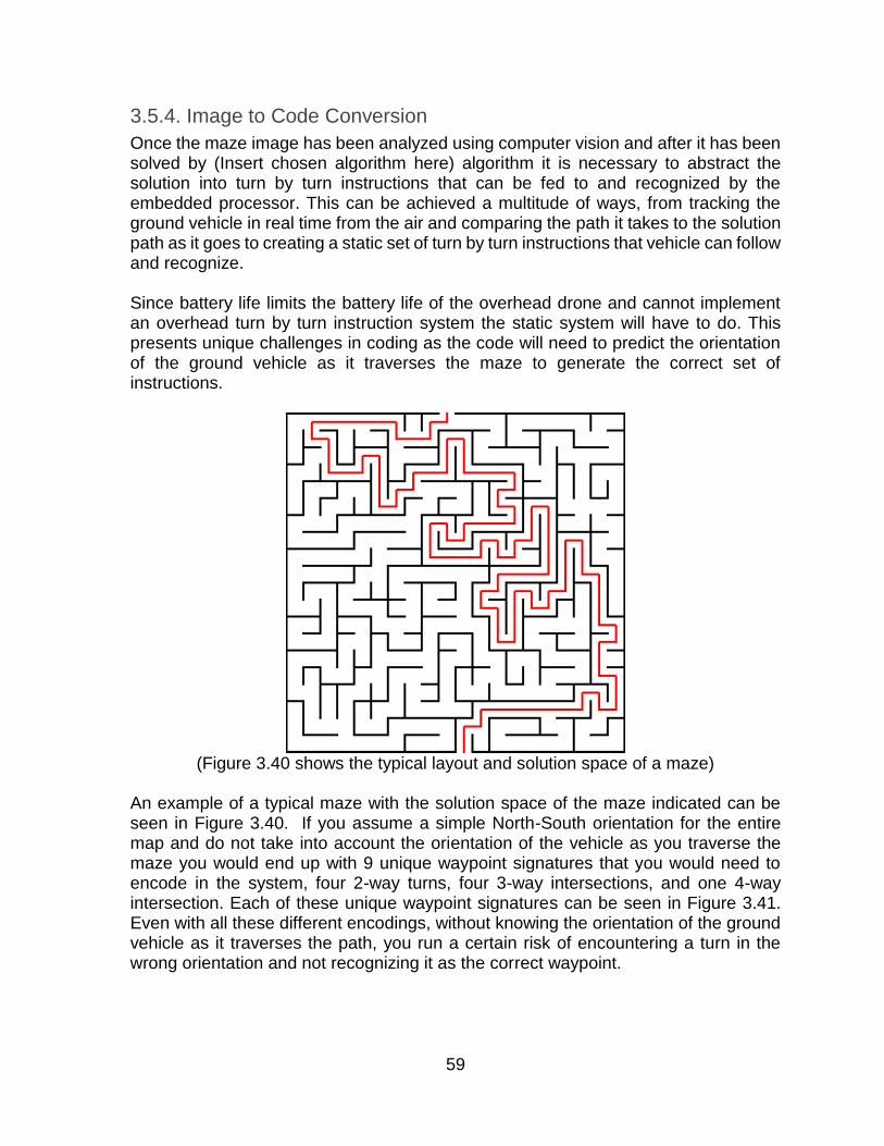
59
3.5.4. Image to Code Conversion
Once the maze image has been analyzed using computer vision and after it has been solved by (Insert chosen algorithm here) algorithm it is necessary to abstract the solution into turn by turn instructions that can be fed to and recognized by the embedded processor. This can be achieved a multitude of ways, from tracking the ground vehicle in real time from the air and comparing the path it takes to the solution path as it goes to creating a static set of turn by turn instructions that vehicle can follow and recognize. Since battery life limits the battery life of the overhead drone and cannot implement an overhead turn by turn instruction system the static system will have to do. This presents unique challenges in coding as the code will need to predict the orientation of the ground vehicle as it traverses the maze to generate the correct set of instructions.
(Figure 3.40 shows the typical layout and solution space of a maze)
An example of a typical maze with the solution space of the maze indicated can be seen in Figure 3.40. If you assume a simple North-South orientation for the entire map and do not take into account the orientation of the vehicle as you traverse the maze you would end up with 9 unique waypoint signatures that you would need to encode in the system, four 2-way turns, four 3-way intersections, and one 4-way intersection. Each of these unique waypoint signatures can be seen in Figure 3.41. Even with all these different encodings, without knowing the orientation of the ground vehicle as it traverses the path, you run a certain risk of encountering a turn in the wrong orientation and not recognizing it as the correct waypoint.
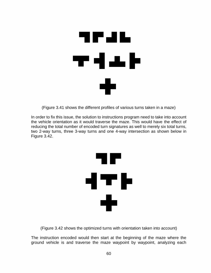
60
(Figure 3.41 shows the different profiles of various turns taken in a maze)
In order to fix this issue, the solution to instructions program need to take into account the vehicle orientation as it would traverse the maze. This would have the effect of reducing the total number of encoded turn signatures as well to merely six total turns, two 2-way turns, three 3-way turns and one 4-way intersection as shown below in Figure 3.42.
(Figure 3.42 shows the optimized turns with orientation taken into account)
The instruction encoded would then start at the beginning of the maze where the ground vehicle is and traverse the maze waypoint by waypoint, analyzing each
61
waypoint to figure out which unique signature the ground vehicle should sense, then updating the orientation based on the turn involved and continuing on to the next waypoint. This however leads the group to another unique problem. While there may not always be repeating turn signatures in the path from one waypoint to another, there exists the potential to be perhaps two 4-way intersections in a row with the second 4-way intersection being the correct 4-way intersection to turn at. There are three ways to solve this issue, to reduce the complexity of the maze down to the complexity of right turns and left turns only, to design the mazes so that this problem is never encountered in any test case, or to encode the system so that it lists every intersection between waypoints so that the ground vehicle knows which turn is correct. The first two cases, while feasible, are not within the spirit of the project and can be considered a non-option. Under this new and more detailed system, the GSC would compute the route into small “Sprints” where every turn from waypoint to waypoint is included in one string, with the last element of that string being the correct turn profile that the vehicle will turn at. This way even if the vehicle encounters two or three turns in a row that are the same it will never be confused as to which is the correct turn to take. This does however place a higher dependency on the sensors to be as accurate as possible so that, should the vehicle drift from side to side within the maze path that it does not recognize that drift as any of the turns along its path.

62
4. Design
4.1. Ground Vehicle Hardware
4.1.1. Motor Controller to Embedded Processor Design
For the ground vehicle, the embedded processor will need to control several motor controllers that are connected to one motor each. This design was agreed upon as the best basic design that could both integrate with the MSP430 board as well as drive the motors at a reasonable rate with sufficient torque. This design also fully describes the pin usage by the motor controllers that will be required by just this specific section of the overall circuit.
(Figure 4.1 shows all connections necessary for the motor controllers) Figure 4.1 shows the complicated connections needed to connect the motors to the motor controllers and then to the embedded processor. This motor controller, the SN754410, is originally designed to connect to one motor per eight pin side, however testing and the specifications of both the motor and the motor controller have shown that the current draw from motor, which could rise as high as 2.2 A, and the maximum rated current draw of the chip along any one line at 1 A is far too much for any one or two line to handle. As such it will require four total chips to drive all four of the motors on this vehicle. The 100nF and 1uF Capacitors between the VCC and the ground on each VCC is to reduce the noise coming from the various parts of the circuit from interfering with each individual chip. The following pins will control the following functions:

63
MSP430 Pin-10 - Left Side Forward Enable. MSP430 Pin-11 - Left Side Reverse Enable. MSP430 Pin-12 - Left Side PWM. MSP430 Pin-13 - Left Side Forward Enable. MSP430 Pin-14 - Left Side Reverse Enable. MSP430 Pin-15 - Left Side PWM. All of the ground pins on the motor controllers will be connected to a common ground that will also be shared by the MSP430. The outputs that are directly controlled by the forward enable pins on the motor controller will be connected together to one side of the motor while the reverse will be connected to the other side to distribute power evenly. In Figure 4.2, an example of a single motor controller and motor pair is shown to more clearly display the connections between them all.
(Figure 4.2 shows the connections of a single motor controller in this configuration)

64
Depending on the power usage of these motors in the field and the current draw to run at maximum RPM, it might be decided to insert current gain circuits at the leads to each motor in order to prevent the motor controller circuit from overheating and burning out. Some manuals also recommended that a heatsink be used, either under or on top of the motor controller, depending on the heat build-up. However testing with the completed prototype vehicle will be required.
4.1.2. Sensor Interface
To design the sensor layout several limitations had to be taken into account based on both the characteristics of the sensor hardware as well as the limited number of pins available on the MSP430 processor. The main constraint on the sensor was that the sensors must be activated in sequence, as firing them in parallel could result in interference between the sensor’s individual readings. The MSP430 is also limited in the number of free pins that are available, so the total number of sensors is limited unless a mux is used.
(Figure 4.3 shows the embedded processor connected to three sensors)
Figure 4.3 shows the necessary layout for the three ultrasonic sensors that will line the sides of the vehicle. The key to this part of the overall schematic lies in the Multiplexer/Demultiplexer circuit that connects the sensors to the trigger pin as well as to the echo pin located on the MSP430 and allows the design to save a pin, using a

65
single trigger and echo pin, and three select lines to run the mux, as opposed to three pairs of trigger and echo pins. The following pins will control the following functions: MSP430 Pin-5 - echo pin for the sensors MSP430 Pin-6 - select line 1 MSP430 Pin-7 - select line 0 MSP430 Pin-8 - enable pin for the MUX/DEMUX (chip is active low) MSP430 Pin-9 - trigger pin for the sensors The CD74HC4052E MUX/DEMUX chip allows for omni directional communication from either the BN/A lines to the A/B0-A/B3 lines or from the A/B0-A/B3 lines to the BN/AN lines. [28] This system can have either two MUX chips, two DEMUX chips, or one of either depending on how it is wired up. Luckily, the design calls for exactly one MUX and one DEMUX chip so this works out well for conserving space on the board. As you can see below in the specification chart in Figure 4.4, the chip also runs off a recommended 5V which means it can easily be connected to the same power source the sensors run off.
(Figure 4.4 showing the voltage characteristics of the MUX/DEMUX chip.) [28]
Like the motor controller circuit above, the sensor chip also has capacitors between the VCC lines and the ground to reduce noise to coming from the other chips on the same voltage line, ensuring that the chip will operate without interruption from other signals.
4.1.3. Voltage Stepper and Battery Eliminators
The overall design for the voltage steppers and battery eliminators that will power the sensors and other sensitive electronics on the ground vehicle will be a two stage design. The first stage of that design is to create a voltage stepper circuit that will drop the native 14V max that the battery runs on to a safe 5V with a maximum 2A current pull for the sensors, Raspberry Pi computer, and the four motor controllers. The

66
second stage voltage stepper that must be created will be connected to the first voltage stepper and will convert the 5V that comes out of that stepper and convert it down to 3.3V and 500mA that will be used to power the MSP430G2553 embedded processor.
4.1.3.1. 14V battery source to 5V 2A Source
The primary chip that will be used in this Step Down DC to DC converter, also known as a buck converter, is the TPS54340 converter provided by Texas Instruments. This is a nine pin converter chip that can be seen in the Figure 4.5 below, with five pins on the left and four pins on the right. Because the pin footprint is small and the pin names are printed on top of one another, Figure 4.6 below has been provided with a short description of the purpose of the pin in the overall design schematic. This table has been taken directly from the datasheet provided by and with permission from TI.
(Figure 4.5 shows the 14V-5V voltage stepper)
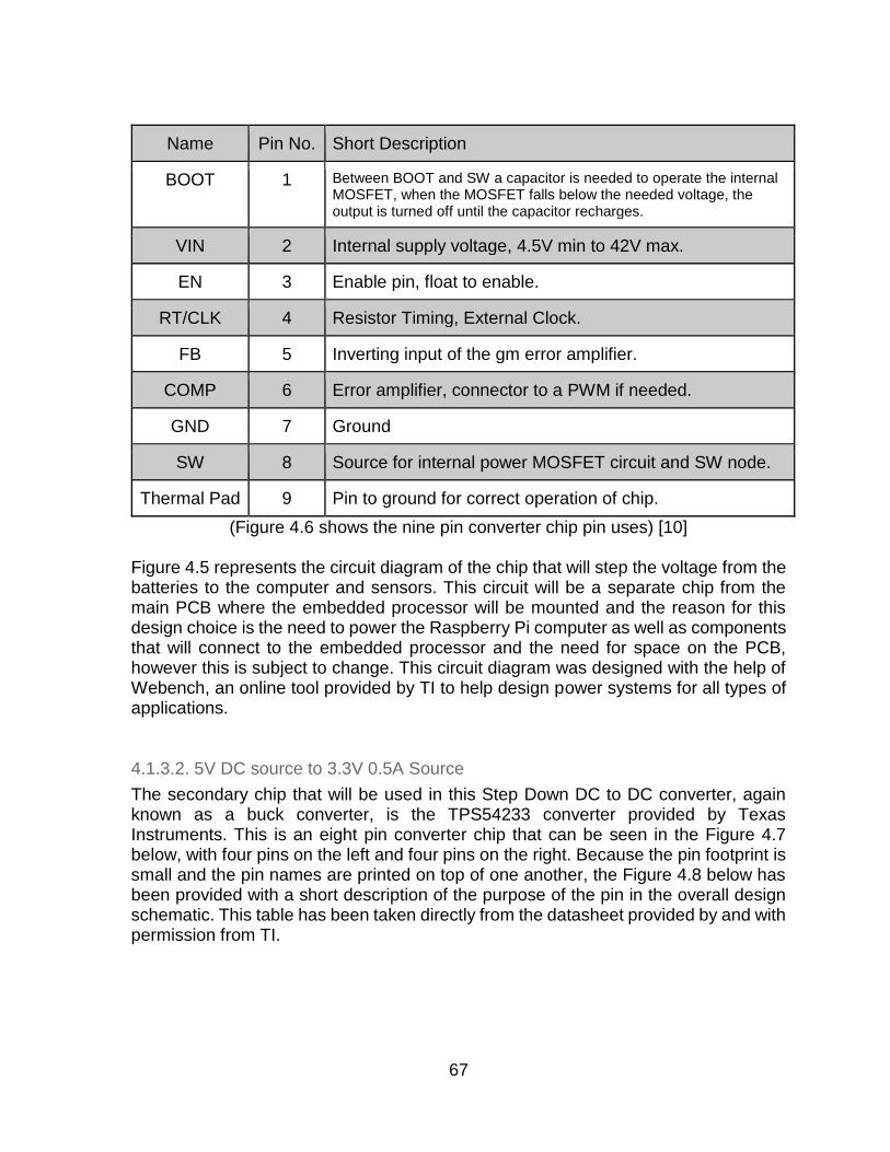
67
Name Pin No. Short Description
BOOT 1 Between BOOT and SW a capacitor is needed to operate the internal MOSFET, when the MOSFET falls below the needed voltage, the output is turned off until the capacitor recharges.
VIN 2 Internal supply voltage, 4.5V min to 42V max.
EN 3 Enable pin, float to enable.
RT/CLK 4 Resistor Timing, External Clock.
FB 5 Inverting input of the gm error amplifier.
COMP 6 Error amplifier, connector to a PWM if needed.
GND 7 Ground
SW 8 Source for internal power MOSFET circuit and SW node.
Thermal Pad 9 Pin to ground for correct operation of chip.
(Figure 4.6 shows the nine pin converter chip pin uses) [10] Figure 4.5 represents the circuit diagram of the chip that will step the voltage from the batteries to the computer and sensors. This circuit will be a separate chip from the main PCB where the embedded processor will be mounted and the reason for this design choice is the need to power the Raspberry Pi computer as well as components that will connect to the embedded processor and the need for space on the PCB, however this is subject to change. This circuit diagram was designed with the help of Webench, an online tool provided by TI to help design power systems for all types of applications.
4.1.3.2. 5V DC source to 3.3V 0.5A Source
The secondary chip that will be used in this Step Down DC to DC converter, again known as a buck converter, is the TPS54233 converter provided by Texas Instruments. This is an eight pin converter chip that can be seen in the Figure 4.7 below, with four pins on the left and four pins on the right. Because the pin footprint is small and the pin names are printed on top of one another, the Figure 4.8 below has been provided with a short description of the purpose of the pin in the overall design schematic. This table has been taken directly from the datasheet provided by and with permission from TI.

68
(Figure 4.7 shows the 5V-3.3V voltage stepper)
Name Pin No. Short Description
BOOT 1 Between BOOT and SW a 0.1 uF capacitor is needed to operate the internal MOSFET, when the MOSFET falls below the needed voltage, the output is turned off until the capacitor recharges.
VIN 2 Internal supply voltage, 3.5V min to 28V max.
EN 3 Enable pin, float to enable.
SS 4 Slow Start pin. External capacitor sets output rise time.
VSENSE 5 Inverting input of the gm error amplifier.
COMP 6 Error amplifier, connector to a PWM if needed.
GND 7 Ground
PH 8 Source for internal power MOSFET circuit and SW node.
(Figure 4.8 shows the 8 pin converter chip pin uses) [11] Figure 4.7 represents the circuit diagram of the chip that will step the voltage from 14V to 5V converter to the MSP430 required voltage of 3.3V. This circuit will be embedded into the PCB where the embedded processor will exist and will supply power to only the MSP430. This circuit diagram was designed with the help of Webench, an online tool provided by TI to help design power systems for all types of applications.
4.1.3.3. Overall View of the Voltage Stepper
The overall design philosophy for the combination of these two circuits is simple, to connect the 5V to 3.3V voltage stepper to the output of the 14V to 5V stepper in parallel with the rest of the components in order to deliver a steady 5V to all the
69
components. the reason why in Figure 4.10 which can be found in section 4.2 Overall PCB Design, the current output Iout1 now displays a 0.5A max current draw is due to the second voltage stepper drawing a max of 0.5A, and though the MSP430 won’t pull that many amps in its operation. The planned connection order after the 5V to 3.3V stepper would be the Raspberry Pi power supply connection, followed by the three sensors in order to prevent the MSP430 and Raspberry Pi from experiencing noise from the other circuits farther up the line.
To connect the batteries to this circuit, a couple of options are available depending on
the needs of the system. The batteries can be connected in parallel, spreading the
current draw across two batteries but reducing the overall voltage down to the base
7V as would be present on one battery. The batteries can also be connected in a
series configuration, which as opposed to doubling the current draw available to the
vehicle, the voltage available to the system would be doubled and all the components
that require a higher voltage, for instance the motor controller and such, would be able
to receive such voltage on demand. For this project it makes more sense to go with a
series connection from the batteries to the voltage steppers as more of the
components depend on a higher voltage rather than current.
4.1.4. MSP430 UART Communication
UART communication to and from the MSP430 happens along one of two channels when using the Launchpad chipset, however once the processor is removed from the Launchpad, the communication channels are simplified to only one channel of communication, the UARTIN and UARTOUT pins located as pins 4 and 3 respectively.
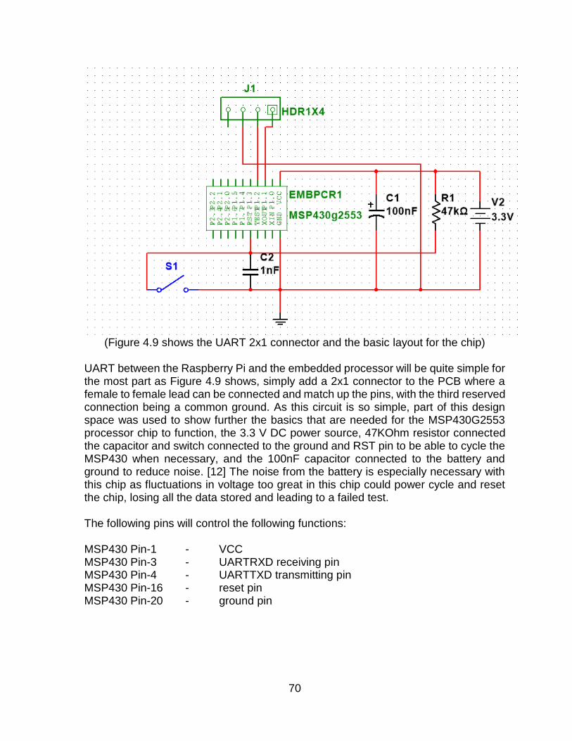
70
(Figure 4.9 shows the UART 2x1 connector and the basic layout for the chip)
UART between the Raspberry Pi and the embedded processor will be quite simple for the most part as Figure 4.9 shows, simply add a 2x1 connector to the PCB where a female to female lead can be connected and match up the pins, with the third reserved connection being a common ground. As this circuit is so simple, part of this design space was used to show further the basics that are needed for the MSP430G2553 processor chip to function, the 3.3 V DC power source, 47KOhm resistor connected the capacitor and switch connected to the ground and RST pin to be able to cycle the MSP430 when necessary, and the 100nF capacitor connected to the battery and ground to reduce noise. [12] The noise from the battery is especially necessary with this chip as fluctuations in voltage too great in this chip could power cycle and reset the chip, losing all the data stored and leading to a failed test. The following pins will control the following functions: MSP430 Pin-1 - VCC MSP430 Pin-3 - UARTRXD receiving pin MSP430 Pin-4 - UARTTXD transmitting pin MSP430 Pin-16 - reset pin MSP430 Pin-20 - ground pin

71
4.2. Overall PCB Design
The overall view of the PCB that will control the ground vehicle can be seen in the Figure 4.10 and Figure 4.11 below. This design, which is a combination of the several smaller circuit diagrams that have been shown throughout this section, is meant to show generally how the connections to the main processor will be handled. Due to software limitations on the number of parts that can be displayed in any one design, it was necessary to separate the total design into two parts, the power systems and the embedded processor, sensor, and motor controls.
(Figure 4.10 illustrates the combined voltage stepper)

72
(Figure 4.11 shows the full PCB layout sans the power supply)
Connections from the power stepper circuits, which are represented in Figure 4.11 as simple DC power sources, will be made in parallel to the embedded processor circuit. This figure, however, does not represent the final layout of the PCB, merely the connections necessary to run all the software, sensors, and motors. In both the Prototyping and final design stages several options for layout will be explored, to reduce the lead length from start to finish as well as to make the entire circuit synchronous.

73
4.3. Software
4.3.1. Ground Vehicle
The ground vehicle main control program will be a combination of many smaller subprograms to control the flow of information from drone to ground station computer to embedded processor.
4.3.1.1. Programming Language
There will be a few programming languages that will be used to code various components of the main and subprograms of the entire system. For the main control program, C++ will be used; for the sub programs, a combination of Python and C++ will be used depending on the specific need of the program in question. For programs that need to run scripts to communicate with the pre-built programs, python or the bash scripting language native to the Linux operating system may be used. For any program that exists on the MSP430G2553 embedded processor, IDE Energia will be used for its compatibility with MSP430 processors and Arduino parts since the ultrasonic sensor will be used as well as the SN754410 motor controllers. Energia is fantastic for controlling the sensors and the motors as it allows the user to specify the pin modes and the digital output of those pins both accurately as well as easily, with a C command to send a high signal along a pin being just: digitalWrite(forward, HIGH);.
4.3.1.2. Ground Vehicle Embedded Main Program
The embedded processor main program has a couple of constraints that guide its design in the long run. The program must have a pre loop that waits for a signal from the main computer and an overall main loop that senses the environment around the vehicle in order to traverse the maze. Besides that the main program must be able to listen to the main computer for the solution sets to be fed to it.

74
(Figure 4.12 shows the main control program on the embedded processor.)
Figure 4.12 above, shows the main control program for the embedded processor on the ground vehicle. On startup of the program the program will enter a loop to wait for a handshake signal from the main program, once it receives this handshake signal it will send a handshake of its own to confirm with the main computer that it is receiving along the UART channel. Error handling will occur at this point, if the two systems are unable to establish a handshake it will throw errors in the main program for debugging purposes. Once communication has been established the program will enter a wait cycle to wait for the transmission of the first instruction set. Once the first instruction set has been received the program will immediately run the sensor subroutine to find whether or not it is at a turn and to make that first turn if required. If not it will begin to move forward and fire the sensors multiple times per second to make sure it doesn’t a turn. Once it senses a turn the control program will then determine by the sensor signature of said turn if the turn is the correct turn to turn at. This will likely be handled by having that turn be at the end of the string with the direction of the required turn immediately after in the sequence. Since the turns will be encoded to unique characters, there will be little need to check for array overflow as all that will need to be done is check for is the current index turn being the correct

75
turn and if it is followed by a turn left or turn right command, otherwise the program will continue. Once the program is at the end of a local solution string it will wait for the main computer to send the next solution set and it begins the loop again, once the program has entered the last solution state the last character in the string will indicate an all stop indicating the ground vehicle has made it to the end of the maze. What is not shown however is the loop that enables the group to determine whether or not the vehicle is within the center of the path and the subroutines that will allow for PWM of the motors to adjust course back to center. Below is the skeleton code that will be used to build the program in energia once the ground vehicle is assembled.
4.3.1.3. Ground Vehicle CPU to Embedded Processor Communication
The ground vehicle CPU to embedded processor subprogram has a few constraints that are necessary for the whole thing to function correctly. The primary requirement of this program is the ability to facilitate this communication along the UART channels. On the GSC side, this communication program only needs to recognize handshakes from the embedded processor. On the embedded side the program must be able to handle the input of entire strings of characters that will represent the turn by turn instructions. Fortunately, for this program on both the embedded side and the main computer controller side, there are many premade programs that allow communication along these channels.
(Figure 4.13 shows the block diagram of the GSC embedded communication
program) Since communication will be through the UART communication ports on the Raspberry PI and the MSP430 processor handshakes will need to be set up for both testing and debug purposes. The whole program will be set up to utilize Pibian’s

76
internal UART commands either through a scripting software or via C++ integration. The wait for program will be necessary to stall the sub program until rest of the process has caught up and the solution result is ready to transmit in batches, this can be shown as the first loop in the Figure 4.13 above. The handshakes will be simple reserved number of character strings that will be used to indicate a ready state so that this program does not jump the gun so to speak and proceed without having a confirmed communication channel with the resulting hardware. The communication at this point will be mostly one sided, with the GSC giving direction strings to the embedded processor and the embedded processor only replying when finished. As testing of this system begins, it may be decide to include some rudimentary error handling on the GSC side to allow the embedded computer to ask for assistance if it finds itself off course on not in the correct sequence, perhaps a form of backtracking that will be communicated along the same channels. Below is a very basic, first prototype of the main control program’s skeleton functions: #define UARTIN 3 #define URATOUT 4 #define echoPin 5 #define MUX2 6 #define MUX1 7 #define trigPin 9 #define Lforward 10 #define Lbackward 11 #define LPWM 12 #define Rforward 13 #define Rbackward 14 #define RPWM 15 void setup() Serial.begin (9600); pinMode(UARTOUT, OUTPUT); pinMode(UARTIN, INPUT); pinMode(trigPin, OUTPUT); pinMode(echoPin, INPUT); pinMode(MUX1, OUTPUT); pinMode(MUX2, OUTPUT); pinMode(Lforward, OUTPUT); pinMode(Lbackward, OUTPUT); pinMode(LPWM, OUTPUT); pinMode(Rforward, OUTPUT); pinMode(Rbackward, OUTPUT); pinMode(RPWM, OUTPUT);

77
void loop() char next_inst; char string[20]; int i = 0; while (next_inst != ‘e’) string[i] = next_inst; i++; next_inst = UARTIN(); int dist, dist2, dist3, dist4; dist = FREQOUT(1); dist2 = FREQOUT(2); dist4 = FREQOUT(3); dist3 = dist - dist2; if ((dist != dist2) && (dist3 < -10)) //PWM to turn back to center else if ((dist != dist2) && (dist3 > 10)) //PWM to turn back to center else if ((dist != dist2) && (dist3 < 10) && (dist3 > -10)) //stay in this range else if ((dist == dist2)) //stay in center char UARTIN() char UARTOUT() void FORWARD() void BACKWARD() void ALLSTOP() int FREQOUT(int i) boolean Left() boolean Right() boolean TForward() boolean TLeft() boolean TRight() boolean 4Way()

78
4.3.1.4. Embedded Processor Sensor Software
The sensor software for the embedded processor has a few important constraints to
the design, firstly it must be linear in design, which means that the sensors cannot be
activated at the same time. This is due to concerns that will be discussed later in this
section. Secondly the program must not have any part of it that can hang up or become
stuck in any kind of infinite loop. As one of the most basic building blocks of this
program and something that will be called multiple times per second in the best case,
if this portion of the program had even a one percent chance of hanging on a function
call or becoming seriously delayed, it will absolutely fail in a way that will cause the
entire project to fail. This type of extreme need for accuracy also calls for the
implementation of certain fail safes and redundancy systems within the program and
the ability of the program to recognize an obviously false result when it encounters
one.
(Figure 4.14 depicting the sensor subprogram)

79
This sensor subprogram, outlined above in Figure 4.14, is what will control the activation of the planned three ultrasonic sensors that will surround the ground vehicle. The design is deliberately linear as there are no pins available on the embedded processor to pulse all three sensors at once and to be able to hear back from them at the same time. It is also unwise to have multiple ultrasonic based sensors firing at the same time as interference from the other sensors could cause a false reading on any one sensor which could lead to a catastrophic failure as out motor control systems are directly tied into this system. While keeping these hardware and conceptual limitations in mind, a 4-1 multiplexer will be employed to cycle through the sensors one by one and fire them with enough of a delay as to reduce the chance of interference between the separate sensors. This will be accomplished by dedicating three pins to be select lines for the multiplexer, and two lines to be the trigger and echo pins on the sensor, reducing the total needed pin count from six necessary pins to five. The program will be on a constant delay loop as can be seen in Figure 4.14 as the first delay loop, to prevent unnecessary slow down on the motors when turning or modulating the pulse to remain in the center of the path, and when it enters the end of this loop it will fire the first sensor. The program will then wait for a response back in the form of an ultrasonic echo and then calculate the distance the object is from the sensor by tracking the round trip time of the soundwave. This distance is stored as one of the distances on the left or right side as dictated by the sensor placement. The program will then fire the second sensor and repeat what it did for the first sensor. These two distances are then subtracted from one another to figure out if the vehicle is drifting to one side or the other within the path. Consequently if either of these values is much greater than the programmed margin of error for drift the program will assume it is at a turn and begin preparations to see if it is the turn to turn at. The third and final sensor to be fired will be the sensor mounted on the front of the vehicle. This sensor value has a dual purpose of preventing the vehicle from colliding with an upcoming wall at a turn and to give a full and accurate picture of the turns it will encounter to the embedded processor. This value, unlike the other two distance values, will not be compared to any other sensor value and will stand alone.
4.3.1.5. Embedded Processor Motor Control Instructions
The embedded motor controller instruction program is perhaps the most complicated subprogram of this project and will be called the most often. The program has five main characteristics that will need to be present and be able to be called on any time throughout the tests. The first characteristic is that the program needs to be able to interface with the sensor program that is also on the embedded processor, with the sensor program feeding the motor controller program information about the environment around it. The next major characteristic is the program needs to be able to move the vehicle forward by default. Following that the program needs to be able to make left and right turns at 90 degree angles in the correct places, further in this section the solution will be discussed. After that the program needs to be able to set

80
the PWM (Pulse Width Modulation) of the motors in order to solve drift within the maze. The final characteristic of this program is to be able to reset the PWM at any time in order to avoid the vehicle making a zigzag pattern while it is attempting to course correct.
(Figure 4.15 depicting the motor controller subroutine.)
The motor control program as shown in the Figure 4.15 above is complicated, but vastly simplified for this specific task of traversing the maze. Once the program is started, it will continue to move until the main control program no longer has any waypoints to move to and thus is at the end of the maze. The most basic aspect of this program is the move forward command. This section of the program will be called the most and to avoid having to constantly digitally write to the pins every time sensing occurs, which will be often. Instead, a set of stored states will be used for each side of the vehicle and if the vehicle is already in a required set state it will not write to the pins. The next portion of the motor control program is a little more complicated. To turn inside the maze, the entire vehicle will rotate about the center axis by the motors on one side of the vehicle to forward and the opposite side to backward with the intent to turn in place much like a tank. The problem will be when to stop turning, and this will

81
be achieved by programming in the profiles of the turns the vehicle will be making, for example if the vehicle will be turning at a T intersection to the left, then logically when it has completed the turn it will sense a wall to the right of it as well as nothing to the front or to the left. The other problem is knowing when the vehicle is in the center of the path in a turn. The only way to solve this without overloading the vehicle with sensors, which won't be practical due to the limitations of pins on the selected embedded processor, is to limit the speed of the vehicle to a known max speed and to count off the time since the turn was first sensed, and to stop the vehicle if the turn is the correct one after a set amount of time. The specifics will have to be worked out in the testing and prototyping phase. The last part of this program but the part that will likely be just as hard as the turning portion to implement will be the center seeking behavior. This portion of the program seeks to keep the vehicle in the center of the path of the maze at all times by sensing the difference in distance between the walls on either side of the vehicle and adjusting the PWM values of the motor to compensate for any drift. Care must be had in this portion of the program with tolerances so that the PWM subprogram does not mistake a turn for drift and so that it also does not mistake drift for a turn and thus throw the sequencing of the solution out of order. To solve this, the program will keep track of the rate of change of the distance values between the two walls, and should that value cross a certain threshold too quickly, the program will automatically start the timer for the turn, even if the distance between the vehicle and resulting wall is too little to set off the turn profile subprogram.
4.3.1.6. Ground Vehicle CPU Main Program
The design philosophy behind the structure of the main control program for this system is linearity and the separate modularity of the separate subprograms that make up the whole. Linear design for most programs is generally a weakness and can lead to inflexible programs that can hang on a step if just the right conditions are not met, however for this project it is essential for the main program to have a rigid, step-by-step structure and to build flexibility into the subprograms. With this design methodology in mind, this project will still have the flexibility of a program that has multiple redundancies built in to the overarching design, yet still has the logical and easy to follow and debug structure that is present in more linear designs. The culmination of this design philosophy resulted in the program flow chart as seen in Figure 4.16 and under this program, the Raspberry Pi computer that will be running this software will act like an information control hub, accepting and transferring data as it sees fit without actually directly controlling any component functions, perhaps aside from the drone’s movement patterns.
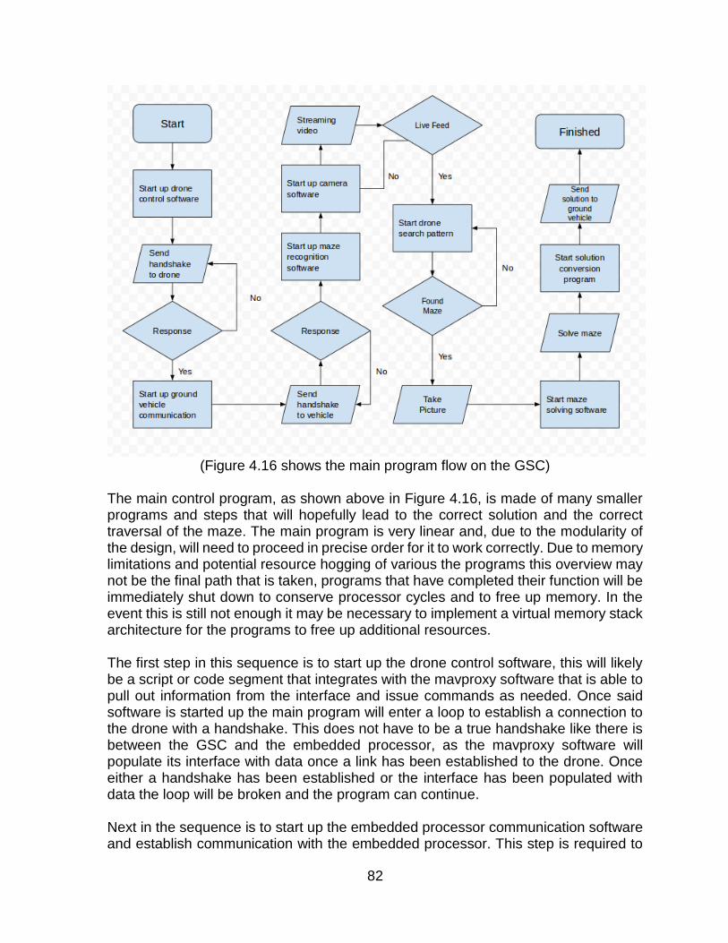
82
(Figure 4.16 shows the main program flow on the GSC)
The main control program, as shown above in Figure 4.16, is made of many smaller programs and steps that will hopefully lead to the correct solution and the correct traversal of the maze. The main program is very linear and, due to the modularity of the design, will need to proceed in precise order for it to work correctly. Due to memory limitations and potential resource hogging of various the programs this overview may not be the final path that is taken, programs that have completed their function will be immediately shut down to conserve processor cycles and to free up memory. In the event this is still not enough it may be necessary to implement a virtual memory stack architecture for the programs to free up additional resources. The first step in this sequence is to start up the drone control software, this will likely be a script or code segment that integrates with the mavproxy software that is able to pull out information from the interface and issue commands as needed. Once said software is started up the main program will enter a loop to establish a connection to the drone with a handshake. This does not have to be a true handshake like there is between the GSC and the embedded processor, as the mavproxy software will populate its interface with data once a link has been established to the drone. Once either a handshake has been established or the interface has been populated with data the loop will be broken and the program can continue. Next in the sequence is to start up the embedded processor communication software and establish communication with the embedded processor. This step is required to

83
have a predetermined handshake that will be sent via UART communication. This program may not be in this exact spot in the load order of the overall program once testing begins, as the GSC has limited resources in terms of memory and resources. Should it be necessary to move it to a later load order it will occupy a position after the solve maze portion of the program. The next step in the sequence is to start up the maze recognition software. This software is likely to take on of two forms, a recognition program that simply will recognize a maze from a picture and signal to the main program that a maze is present in the picture, or a recognition program that recognizes the maze, cleans the image to see if the maze is of an appropriate clarity to solve the maze, then creates the solution and stores it as a string. If the latter is what is decided upon, the program to solve the maze will not be used and the control software will have to be reworked. The next and perhaps the most important piece of software to be used is the communication software between the camera mounted on the drone and the GSC mounted on the ground vehicle. This software will have to be suitably complex to be able to detect whether the feed is live and not simply static, as well as detect whether the camera is leaving the range of operation and to issue commands to the drone control program to bring the drone back into the area of operation. This program will not need to issue any commands to the camera as the camera simply has a TX module mounted on it and is only capable of transmission of its feed. Once a suitable feed has been established the main program will break out of its loop and will continue on. The next program will establish one of two search patterns for the maze, either a height based search where the drone will climb to a great height and take a picture, analyze the photo for the maze, and adjust the height as needed to get a clear image to solve, or to search along a grid pattern in order to find at least some part of the maze and then to adjust from there, but all from a predetermined height. Once the maze has been solved the program will command the drone to return to “base” and the picture that it took will be analyzed. Once this is complete the GSC on the ground vehicle will start up the maze solving software and solve the maze. This program may be merged into the solution conversion program so that one program both solves the maze and converts the solution to a format that can be used by the embedded processor. Once a solution has been found and converted the solution will be passed to the embedded processor piece by piece as it solves the maze.
4.3.1.7. Ground Vehicle To Quad Communication and Control
The ground vehicle to drone communication is a two part affair and requires the integration of the drone autopilot software and a small message passing software. As can be seen in Figure 4.17, which is the flowchart for the drone autopilot program, the drone will follow a certain protocol in order to find the maze on the ground below,

84
however what the flow sheet doesn’t show is how the main program will communicate with the drone controlling software, Mavproxy. Due to the way mavproxy works and accepts commands in order to control the drone, via the command terminal, it will be necessary to design an interface program that can convert the specific commands that the maze seeking software output to the drone controller specific commands. The program will also need to pull information from Mavproxy in order to save it for feeding to the diagnostic systems that will be separate from the GSC. Figure 4.17 shows the general flow of the message passing software that will interface from mavproxy to the main control program.
(Figure 4.17 shows the general program flow of the drone.)
In order to be effective the message passing software will need to be able to convert
every possible command that will be returned from the map seeking software. Move
to specific gps waypoints, change altitude, move x meters in any direction, and return
to base are just a few of what will need to be coded into the program. As opposed to
the main program it is likely that this program will be written in python or a similar
language native to Linux, like bash in order to interface with the terminal that mavproxy
will be running. Figure 4.18 shows how communication with the drone will occur.

85
(Figure 4.18 shows how the drone communication software will be laid out)
4.3.1.8. Ground Vehicle to Camera Communication
The ground vehicle to camera control software will be a simple affair, as what can be used is VLC video player in order to access the live stream from the camera. From here a simple script can be created to take a still from the stream for analysis by the main program at the signal from the main control program. Figure 4.19 shows the video stream capture setup options for VLC. Should VLC end up not being versatile enough for this project, an alternative would be to use MPC by CCCP in order to capture the stream.
(Figure 4.19 shows VLC’s stream capture mode.)

86
4.3.2. Quadcopter
4.3.2.1. Autopilot
The ArduCopter autopilot system has various built in flight mode that will be helpful in implementing this project. The first mode that the pilot should become comfortable implementing is the stabilize mode. In stabilize mode, the throttle control will vary the quadcopter’s average motor speed. The yaw control will vary the rate of change of the heading. When the yaw control is at zero, the heading will remain constant. The most important aspect of stabilize mode is the pitch and roll control. As the pitch or roll control is varied, the quadcopter’s angle will be varied. With controls set at zero, the quadcopter will remain level. Stabilize mode will allow for simplified controls for the user, but constant changes must be made in order to maintain a constant vertical or horizontal positions. This only allows for autonomous control of the yaw axis. This mode will be useful for manual control, but as will not be useful for autonomous control. The next flight mode to implement is altitude hold mode. In altitude hold mode, the pitch, roll, and yaw are all controlled in the same manner as stabilize mode. The difference is found in the simplification of the vertical control. The throttle stick around mid-level will maintain the quadcopters altitude based on the altimeter measurement. Variance of the throttle stick will control the rate of change of the altitude. This allows for autonomous control of the yaw axis as well as the altitude. Manual control of the pitch and roll axis are required to maintain horizontal position making this mode only useful for manual control. The next flight mode that will allow for autonomous control is loiter mode. Loiter mode implements the same yaw and altitude control as altitude hold mode, but the pitch and roll axis are autonomously controlled by the flight controller to compensate for any horizontal drift. The flight controller uses the global positioning readings paired with accelerometer readings to allow the quadcopter to hover in a fixed location without any manual compensation needed. Pitch and roll controls allow the user to vary the rate of change of horizontal movement. Loiter mode is essential for autonomous flight as it will allow the quadcopter to be completely controlled by simple digital instructions. The last mode required in order to implement fully autonomous missions is the return-to-launch mode. Prior to flight, the flight controller must be armed. When the flight controller is armed, the global positioning coordinates are noted as the home location. This location will be used for landing in the return-to-launch mode. When this mode is activated, the quadcopter will return the home coordinates at a pre-programmed altitude and loiter for a pre-programmed amount of time. The quadcopter will then descend to ground level until it has safely landed. This mode is required for fully autonomous missions as well as a useful safety feature. If the quadcopter loses a link from the telemetry command center, this mode will automatically be implemented in order to preserve the quadcopter. Once stabilize, loiter, and return-to-launch modes are working effectively, auto mode is ready to be implemented. Auto mode utilizes all of the autonomous features of

87
these modes in order to autonomously complete a pre-programmed mission. The mission will primarily run off of predetermined waypoints that vary by coordinates as well as altitude. The quadcopter will often launch itself at the beginning of the mission, progress through each waypoint, then execute a return-to-launch command. Auto mode will be the main means of autonomously completing the objective. A summary of each flight mode and its range of control is shown in Figure 4.20.
Autonomous Control
Yaw Pitch Roll Altitude Coordinates
Flight Mode Manual
Stabilize X X X
Altitude Hold X X X X
Loiter X X X
Auto X X X X X
(Figure 4.20 shows the range of control of each flight mode)
4.3.2.2. Ground Control Station
In order to implement autonomous control, the quadcopter must be able to be controlled by a ground control station. The developers of the ArduCopter autopilot system have also developed a ground control station called Mission Planner. This ground control station will be extremely useful for tuning the flight controller’s various modes. Mission Planner also generate an easy to use graphical user interface, which can be seen in Figure 4.21, that can either monitor or control the flight controller through a telemetry link. The ability to switch among various flight modes will be useful for developing the flight modes as well as a backup in case of radio transmitter failure.

88
(Figure 4.21 shows Mission Planner’s UI)
Mission Planner will also be useful for testing the basic functionality of auto mode. This ground control station allows the user to load a mission onto the flight controller prior to flight and access it at any time. It also allows the user to input individual waypoint for the quadcopter at any time. Though these are useful functions, it is necessary to be able to constantly update the mission while the quadcopter remains in flight. Mission Planner does not support this functionality. This functionality is supported through the MAVLink protocol. Once auto mode is calibrated and running smoothly through Mission Planner, a new ground control station will be needed that supports the MAVLink protocol. MAVProxy is a ground control station that will be able to implement MAVLink commands through the telemetry connection. MAVProxy’s interface is shown in Figure 4.22. MAVProxy will be most useful using its command line interface. This will allow for various python scripts to be run in order to implement the flight controller’s auto mode in various ways by updating the waypoint mission through the MAVLink protocol. Through MAVProxy’s command line interface, telemetry data, such as altitude and coordinates, can be read and used to assist in the image processing.

89
(Figure 4.22 shows the mavproxy terminal and control screens)
4.3.3. Image Processing
4.3.3.1. Object Detection
Object detection is heart of the Drone Maze Zone project. Locating the object which is the Maze in this case will be taken care of with object detection program. In order to find the object in the given area, object needs to be color coded. The color of the object must be something that can easily distinguished from its surroundings, so a neon pink or neon green would be a great choice. Images are getting saved as a matrix of three values for the pixels. These are normally the amount of Red, Green, and Blue that combine together and create an actual value for each pixel. This is a simple way of storing the image, but not useful to find an object using colors. Because the object lighting can be different. Finding object by its color using RGB values is not easy and practical for this project. An alternate and practical way of detecting object is by detecting its Hue. In order to find the HSV values, a custom HSV detector program is designed. This program will test the object and returns the amount of Hue, Saturation, and Value. The quantities will be used in the main program to filter the color coded maze and separate it from its surroundings. A wide range of saturation and value and a small range for the Hue filter the color regardless of the lighting. An example of the HSV detector output is shown in Figure 4.23.

90
(Figure 4.23 shows the HSV values of the object)
For the sake of simplicity, openCV library and python programming language are used for the image processing and codebase respectively. So openCV library is imported at the beginning of each program. When the right amount of hue is detected, it can be used to filter the color from its surroundings. This can be done by masking the image. Before any modification is made in the original image, a copy is made to be used in the future modifications. An outline of this process is shown in Figure 4.24.

91
(Figure 4.24 outline of finding the hue and filtering the color)
Picture is matrix of pixels and each pixel has a value based on its color. In this case it can be range from 0 to 255. The range of detected hue for the neon orange is 5 to 11, so all the pixels in that range will be masked and separated from the surrounding. This is shown in Figure 4.25.
(Figure 4.25 shows the image with the masked color)

92
The main program starts with initializing the camera. This process requires installing the correct driver for the camera and importing it using an OS module into the python program. Then a two second pause was given for the camera to be initialized and warmed up. After this step two variable that correspond the height and width of the image are defined. This variables will be used later in the program for finding the location of object in the image and testing purposes. After this step ,the whole program is wrapped in a while loop, that makes the program to run, take images, analyze the colors, and return an output that can be used for the quadcopter navigation until quadcopter is in the range of the final shot. In the while loop first an image will be taken using openCV function cv2.VideoCapture(), and then the image orientation will be fixed using cv2.flip(). cv2.VideoCature returns two value, the image and a Success value. Image is the actual image in RGB format and the Success is set to true if the image is taken successfully.
Next step is reducing and clearing the noise from the image. This can be done by
cv2.GaussianBlur. The output of this function is a clearer image that will be used for
the following step. An example of a noise reduced image is seen in Figure 4.26.
(Figure 4.26 shows the image before and after noise reduction)
After reducing the noise from image, the required color which in this case neon orange,
will be masked. Now the borders of the object can be detected by using
cv2.findContours(). Contouring can be explained as individual connections between a
series of points that all share the same Hue and color characteristics. Contour is a
useful openCV function that can be used to find the cluster of pixels with same value
for hue. It is useful for this project to draw a line between the object and its
surroundings. The center of the contour can be considered as the coordinate of the
object with respect to the image borders. Contour can be also used as an indicator of
distance between the object and the camera. The result of this part will be used to

93
calculate the distance between the object and the camera. An example of a contour
is shown in Figure 4.27.
(Figure 4.27 shows the use of contours)
The next part of the code will divide the image into thirteen different areas and locate
the object with respect to those areas. Area one through eight are basically cardinal
directions. Area nine through 12 are fine tuning to prevent drift as the altitude is being
changed. Area 13 is the center point and target size of the maze inside the image.
Figure 4.28 shows an example of the 13 areas. Based on the location of object and
whether or not it is in the frame of the image, program outputs a command which
contains the location of the object or a none value. For instance if the object is in area
one, program outputs 1 and the quadcopter controller sends a signal up and right to
the quadcopter.
(Figure 4.28 represents the 13 different areas of the image)

94
Quadcopter flies high enough that the proportion of the image size to the maze is
about 12 to 1. That means if the maze is captured in the image, the size of maze with
respect to the image is about one the areas. The following chart Figure 4.29
represents how the image processing program outputs a value base on the location
of the object in the taken image.
(Figure 4.29 shows the outline of finding the object)
4.3.3.2. Maze Manipulation
When the final shot was taken, the image gets converted to a Portable Gray map or
PGM format and sent to the Canny Edge Detection program. The converted image is
a matrix of pixels that can be read and imported to the edge detection program. The
way edge detector works is by convolving the image matrix with the Gaussian function.
Using the bell curve shape Gaussian function as a filter makes it ideal to smoothen an
image, without having sharp edges and kinks in the output. The following equations
are Gaussian function and its derivative that are used to filter the edges.

95
The edge detector, reads the PGM image as a matrix of pixels, and then convolve it
with the Gaussian derivative function. Since the convolution is performed in both X
and Y directions, the result will be passed to a function that is responsible to calculate
the magnitude of each point by taking square root of 𝑋2 and 𝑌2. Then Magnitude
will be passed to another function that is responsible to remove the noises from the
actual edges. As it was mentioned before finding the edges is possible by finding
jumps in the colors in different parts of picture, but sometimes these jumps can be
seen in different parts of pictures that are not actually the edges. Normally edges are
built form contiguous pixels that are in the color threshold. To filter the noises from
the actual edges, only the points that are picked and neighbor to another pick point
will be chosen. That means those points that are picked as edges, but are not neighbor
to another peak pixel, will be discarded.
When the edges are detected, the edge detection program outputs the final result to
the maze solving program. Maze solving program convert the input to its required
format, solve the maze, and output the result to the Ground Vehicle controller.
The pictures below in Figure 4.30 represent the steps that are taken to separate the
maze edges from its surroundings.

96
maze from the above converted image to pgm format
peak points in the image maze edges
(Figure 4.30 shows the steps to find the maze edges)
4.3.3.3. Maze Solving Algorithm
The morphological way of solving the maze is the cleanest and easiest way to solve
the maze in minimum steps. It utilizes the power of image processing using openCV
libraries. The only drawback of this method is that it only works for a simple perfect
maze that has only one solution. The output image from the edge detection part will
be used as an input for the maze solving program. After filtering the edges and
separating those from its background, the output will be converted to a gray value
image. Maze solver uses the binary image and solves it using a mathematical
morphology. It first labels the walls in the binary image, and then separate the walls in

97
the image and splits the maze in two different parts. From this point, solution can be
easily seen. This process is shown in Figure 4.31.
(Figure 4.31 shows the steps of morphological maze solution)
When the maze solution is found, it will be translated to a series of instructions that
can be used for the ground vehicle movement.
4.3.4 Full Build Materials List
Below in Figure 4.32, Figure 4.33, and Figure 4.34 is the full list of materials required
for this project.

98
Item Description Number
MSP430G2553 Embedded Processor 1
Modular RX for USB USB receiver for 5.8 Ghz band 1
5.8Ghz Camera Tx combo
Camera and Transmitter 1
Raspberry PI 2 Model B Ground Station Computer 1
SR-04 Ultrasonic Sensor 3
CD74HC4052E Mux/Demux chip 1
M2545-4-K 4-Pin Male PCB connectors 9
BOB-12035 Micro USB power output. 1
100nF Capacitor 100nF Capacitor 9
1nF Capacitor 1nF Capacitor 5
SN754410 Motor Controller chip. 4
34:1 Metal Gear motor 34:1 Metal Gear motor 4
COM-00097 Mini switch button. 1
47 KΩ Resistor 47 KΩ Resistor 1
7.4v 3200 20C Venom 7.4 LiPo Battery 2
Dagu Wild Thumper Chassis
Chassis 1
Dagu Wild Thumper Wheel
Wheel 4
Series Battery Connector Series Battery Connector 1
Battery Charger Adapter Battery Charger Adapter 1
Onboard Low-power Alarm
Onboard Low-power Alarm 1
PCB Printed Circuit Board 2
(Figure 4.32 ground vehicle: embedded motor controller build list)

99
Item Description Number
TPS54340 14V - 5V Voltage Stepper 1
TPS54233 5V - 3.3V Voltage Stepper 1
B340A-13-F 0.5V 3A Zener Diode 1
MBR0520LT1G 0.385V .5A Zener Diode 1
100nF Capacitor 100nF Capacitor 2
18nF Capacitor 18nF Capacitor 1
8.2nF Capacitor 8.2nF Capacitor 1
6.2nF Capacitor 6.2nF Capacitor 1
47uF Capacitor 47uF Capacitor 2
10uF Capacitor 10uF Capacitor 1
4.7uF Capacitor 4.7uF Capacitor 1
330pF Capacitor 330pF Capacitor 1
4.7pF Capacitor 4.7pF Capacitor 1
33uH Inductor 33uH Inductor 1
6.8uH Inductor 6.8uH Inductor 1
1MΩ Resistor 1MΩ Resistor 1
86.6KΩ Resistor 86.6KΩ Resistor 1
53.6KΩ Resistor 53.6KΩ Resistor 1
20KΩ Resistor 20KΩ Resistor 1
11.5KΩ Resistor 11.5KΩ Resistor 1
10.2KΩ Resistor 10.2KΩ Resistor 2
10KΩ Resistor 10KΩ Resistor 1
3.24KΩ Resistor 3.24KΩ Resistor 1
(Figure 4.33 ground vehicle: power stepping component list)

100
Item Description Number
Flamewheel F450 Frame 1
APM 2.6 Flight Controller 1
Sunnysky X2122 Motors 4
Afro 20A Electronic Speed Controllers 4
Clockwise Locking Nuts Nyloc Nuts 4
Turnigy 5000mAh 3s 20C Lipo Battery 1
Lipo Battery Alarm Battery Low Voltage Monitor 1
SkyRC IMAX B6AC Battery Charger 1
Bluecell Lipo Guard Lipo Charging/Storage Bag 1
3DR uBlox GPS/Compass Kit
GPS/Compass 1
Hobbyking 4 Channel Transmitter
Transmitter 1
Hobbyking t6a-V2 Receiver 1
3DR Radio Set 915 MHz Telemetry Set 1
APC Propellers 4
Quiyun Male to Male Servo Leads
Servo Connectors ?
(Figure 4.34 Drone: full component list)
101
5. Prototyping
5.1. Stage 0 Prototypes
Prototyping for this project will progress in a series of steps, the first being dubbed as the stage 0 prototypes as they will be a series of tests to make sure the designs that were presented are actually viable in the long run. The primary medium of this prototyping stage will be the basic breadboard and breakout boards for the various components along with prototyping resistors and specifically the MSP340 Launchpad. Specific component prototypes to be built during this stage are as follows:
Motor Controller circuits from Launchpad to breadboard to motor Sensor Circuits from sensor to Launchpad. Sensor Circuits using all 3 sensors and the multiplexer. Voltage stepper circuits and their connections to the various circuits. Drone components before final assembly. Maze 1 and Maze 2 fall in this category.
Specific software prototypes to be built during this stage are as follows:
Motor Controller Software for 1-4 motors. Sensor software with and without the multiplexer. UART communication to and from the MSP340 using the hardware pins. UART communication to and from the Raspberry Pi using the tx rx GPIO pins. Computer vision programs on the Raspberry Pi Maze Solving Software on the Raspberry Pi Mavproxy scripting software on the Raspberry Pi Streaming software from the 5.8 GHz channel to the Raspberry Pi
Once these designs have been tested at this stage they will be certified for transition to the stage 1 prototyping phase and work will begin on designing the eventual layout of the stage 2 and final production models.
5.2. Stage 1 Prototype
Stage 1 prototypes will move from the constraints of breadboard for development to the relative freedom of perf-boards and hand traced lines. This stage of the prototyping will be the first time all the components will be assembled together and tested together on the chassis along with the connection to and from the drone. This stage of prototype will also likely have most if not all of the production software running on the various components to test all the different latencies once all the relevant circuits are built. Specific hardware goals for level 1 prototype:
Integration of the sensor and motor controller lines and chips onto one combined chip.

102
Integration of the Voltage stepper circuits into one combined chip. Assembly of the drone and camera package. Assembling voltage stepper for camera. Assembling maze 3.
Specific software goals for level 1 prototype:
Completion of prototype or final main control program to be run on the Raspberry Pi.
Completion of prototype or final main control program to be run on the MSP430. Specific Design Aspects to be tested:
Heat dissipation of the assembled chips. Feasibility of stacking the GSC on top of the embedded motor controller PCB. Optimum angle at which the sensor will detect the walls correctly. Actual battery life of the ground vehicle. Actual battery life of drone.
From these goals and the subsequent testing of the level 1 prototype, the software components that were designed in the first portion will be fined tuned to overcome any flaws in the programming that the level 0 prototypes could not predict. Since this will be the first time the various subprograms will be running together under a master control program there is expected to be some quirks in the operation and these will be accounted for when the time comes. Specific point of concern that will be looked at are the integration of the communication software to and from the main computer to the fully assembled drone and the main control program as well as the main control program’s ability to run all the software successfully on a headless system. For the hardware, certain characteristics of the perfboard construction will be a testing ground for the final PCB layout with everything like component layout and trace lengths being looked at. Since it will be the first time all of the components will be together on one chip, temperature will be monitored on all the components, especially the motor controllers and the embedded processor. During preliminary parts testing it was found that the motor controller chips had a tendency to get rather hot and knowledge of that at this stage could lead to the addition of a necessary heatsink to radiate the waste heat away.
5.3. Stage 2 Prototype or Final Prototype
Stage 2 prototypes, or the Final prototype, will incorporate everything learned in the first two round of prototyping into a final product. The reason why this is not called simply the final prototype is due to the chance that something needs to be changed once the first PCB is received from the manufacturer or the build quality suffers on any of the incarnations. Most of the changes to this prototype from the previous ones

103
will be via the PCB as the software at this stage should be fully complete and functional. Specific hardware goals for this level of prototype:
Testing the PCB style layout and lead length for any potential problems resulting from inductive resonance.
Heat dissipation on this production level scale. Function of all the components once fully assembled.
Any changes to the board layout or subsequent changes to components at this stage will not advance the prototype stage number.
6. Testing
6.1. Maze Design
When testing begins with the first prototypes of the ground vehicle, a series of mazes will need to be built with the final design characteristics in mind in order to test various aspects of both the hardware and software implementations that will compiled. The basic aspects of the maze that will be constructed are as follows:
The maze will need physical walls that can be sensed by the ultrasonic sensors that will be mounted on the ground vehicle.
The maze will need to have a Start and a Finish area that can be discerned from the air by the drone.
The maze will need an easily distinguished background from the testing environment.
The maze will need a high contrast color to the background painted on the top to distinguish edges from paths.
The maze will need at least one of every type of turn. The maze must have only one solution.
Prior to testing with a maze, simple tests can be created to simulate the maze in segments. Firstly the quadcopter’s locating abilities should be tested. This can be done by putting a painted square in an open area. The drone’s ability to locate that square will be simulated by the square without the need to assemble an actual maze. For the ground vehicles ability to navigate a maze, sections of the maze can be assembled in order to test those particular sections. Firstly, single turns should be tested individually. Once each turn has been tested, various combinations can be tested in order to ensure the ability to not only navigate turns, but to navigate the sections between turns.

104
The first maze that will be built for testing will be small in size so as to be easily constructed inside an apartment environment, the solution will only take the ground vehicle through the minimum number of turns, one of each type, and will be a testing ground to see what does and does not work in the overall maze design as well as software design. The first maze will be a testing ground for all the software that will be built up to that point without having to mount it to the various vehicles to test it. Virtually every system that is designed will have to be tested at this small scale to fine tune the various programs, the camera system will be tested to make sure the resolution and build quality is appropriate as well as the software behind the scenes being functional. The second maze that will be constructed will be of similar complexity to the first maze, but will incorporate the findings from the first test maze and will be used to test the stage 1 prototype and the completed drone in a production environment on the small scale. Some test that will be performed on this maze will be the image recognition of the maze in the uncontrolled environment of outdoors, with varying lighting conditions, exposure and focus levels. The stage 1 prototype and the stage 2 prototype of the ground vehicle will be tested on this maze before being taken on to the primary testing maze to make sure all the components were correctly assembled and to test the speed capabilities of the vehicles. The third maze will be much larger than the previous two mazes, up to four times the size of the second. The design of the third maze will follow the maze specifications but for the sake of the project will need to be modifiable and be able to be broken down into individual sections for easy transport. The modifiable requirement is so that each test of the maze is able to be randomly generated to a degree to test the systems under different conditions.
6.2. Image Processing
6.2.1. Setting up the PI and Installing the Requirements
Before running the image processing software on the Raspberry PI, the following steps are required to test and confirm that PI has enough processing power to run the image processing software as well as other programs.
Install Raspbian
Enabling camera and time through configuration utility
sudo date -s "Tue Nov 23 19:20:00 UTC 2015"
Install python imaging PIL sudo apt-get install python-imaging

105
sudo apt-get install python-imaging-tk
Updating all current software sudo apt-get update sudo apt-get upgrade sudo rpi-update
Install openCV
sudo apt-get install libopencv-dev python-opencv
Fix openGL window issue sudo apt-get install libgl1-mesa-swx11
Install the PI camera
sudo modprobe bcm2835-v4l2
Test the camera raspistill -w 1024 -h 600 -o image.jpg to take an image raspivid -o video.h264 to record a video fswebcam -r 640x480 image.jpg for the USB webcam
Before connecting the Wireless camera, image processing can be tested by PI
camera. The main and most important test is to find the Hue, Value, and Saturation of
the object which is the Maze for this project. The Background and walls of the maze
are required to be a color that can be easily distinguished from the surroundings. The
color can be any neon color such as neon pink or neon orange. Once the drone is fully
assembled and the communication system is in place, the same tests will be repeated
on the production system for accuracy.
6.2.2. Maze Identification
The first type of error that needs to be considered and tested in image processing step
is color detection error. To identify the Maze, various colored objects were tested.
Each object was first tested with an HSV detector program to get its exact amount of
Hue, Value and Saturation. Then the amount of Hue was used in the object detection
program to filter the color from its surroundings. When regular colors such as red,
green, or gray were used for the object, a high percentage of error in detecting the
object was observed. The percentage of error was even more significant when the
object was not close enough to the PI camera. The program was not able to detect a
single object due to the conformity to its surroundings and amount of the environment

106
light. The exact same test was performed with neon colored objects and the error was
almost about 70 percent less than what was observed with regular colors.
Second type of error can happen is when the object is far from the camera. This cannot
be easily prevented just by changing the object color. The quality and resolution of the
picture plays a significant role to avoid this problem. Due to the restriction of the size
and weight for the camera, increasing the resolution and the quality for the camera is
not possible for this project. To avoid this issue, the proportion of size of the maze to
the picture should be at least one to ten. To get the best result, quadcopter should not
fly above a certain altitude and range from the maze.
To discover which specific color and what maximum altitude the maze identification
software can detect the maze at, the production camera will be needed for the correct
final saturation that will be present for the final tests. With this camera then, several
mock mazes will be tested with various colors and at various altitudes to simulate the
action of flying at different altitudes. Once the optimum altitudes and colors have been
discovered, they will be used towards the construction of the final mazes as well as
the final programming of the drone control software.
6.2.3. Maze Required Resolution
The required resolution for the maze is more of a general term to describe the required
size of the maze in the camera’s view space to get an accurate and workable image
and depending on the size of the maze in general this required resolution could vary
wildly. This test and series of tests that will be run will encompass several of the
programs that will be running and will not address any one specific software
component. The first program that can affect the maze required resolution is the maze
manipulation software. This software is what bleaches and prepares the image that is
taken for the maze solving algorithm to solve and the accuracy of the program at this
stage can wildly affect the function of the overall test. If the resolution on the maze is
too low, say the maze is too large and the drone is too far from the maze, the image
manipulation software, specifically the edge detection software, might create a wall
where there isn’t one or create a turn where there isn’t one. So to alleviate this issue,
several tests will be run to not only determine the optimum height for a maze of a
certain area, but to also determine the upper limit of a maze that can be created and
successfully traversed. Before the ground vehicle is fully assembled, this test will take
the form of a small mock up maze drawn on a sheet of paper with the background
color and walls being what will be used in the final tests and pictures being taken at
different simulated altitudes from the paper. This will give a rough estimate as to the
upper limits of the drone and maze size.

107
Another potential source of distortion for the image which must be accounted for is not
so much software as hardware, the vibrations that are produced from the quadcopter
itself. These vibrations at the wrong frequency can give a double image out of the
camera and make any image useless on the return. To test this potential issue the
drone will need to be assembled first and properly calibrated for the weight of the
camera before several test shots are taken from various altitudes and in various types
of weather. If the distortion from the motors is too great to get any kind of decent
image, isolation hardware will be explored though it is unlikely this will be needed in
the long run as standard FPV gear for enthusiast drone pilots give a reasonably steady
picture.
6.3. Ground Vehicle Control
6.3.1. Sensors
The sensor testing will encompass several distinct aspects that will drive the preliminary and final design of the ground vehicle. The aspects in question are as follows, accuracy, optimum mounting angle and position, maximum distance, minimum distance, and interference. The testing of accuracy will be used in all aspects of these tests and will be the primary metric used when determining the best of what is being tested. Accuracy will first be calculated for each sensor that is tested, with each sensor being set up on a small test bench and sensing the distance of objects at predetermined points along a flat plane, or instance 5cm, 7cm, 12cm, and 50cm. this will give the project a baseline to work off when determining the characteristics of each sensor as well as every sensor overall. The next test that will be run is the optimum angle and position of the sensor on the ground vehicle. Due to the way the chassis is constructed, it may not be possible to mount the sensors on the side of the vehicle between the wheels as would be optimal, instead it may be best to mount the sensors on the top of the craft have them sense from there. This, however, leave the project with the problem of having to build the maze walls higher than expected. To solve this issue, it has been proposed to angle the sensors at a precise downward angle so as to sense the wall without having to have the wall be unrealistically high. As the sensor is based on ultrasonic technology, it is possible that this arrangement might decrease the accuracy of the sensor to below acceptable limits and will cause errors in the tests, however it is hoped that it will be of no issue. The minimum and maximum distance of the sensors are important to be known for several reasons, if the minimum sensing distance is too far, it could invalidate that sensor as a part of the design, if the maximum sensing distance is too short, the same thing will occur. The minimum sensing distance must be no farther than 3-4cm for an

108
individual sensor and the maximum sensing distance for any individual sensor must be farther than 25cm in order for the part to be suitable for this project, the farther and shorter these two values are the better as more can be done on the programming side and the more wiggle room is available to the programmers. Interference for the sensor is a general term that encompasses several concepts from the PCB design to heat wave distortion and crosstalk between sensors. What will be tested primary in the first round of testing will be crosstalk between the several sensors, where the firing of one sensor results in a false reading, usually a shorter distance than what should be sensed, being returned to the program. This problem is being designed out from the hardware level to the software level and is a primary concern, however there is still the chance that the safeguards on every stage will fail and to know when one of these cases will fail will be invaluable to both the design of the hardware and software on the ground vehicle as well as the design of the maze itself. Interference of the PCB level and due to heatwave distortion of the air surrounding a hot object, while not as obvious as crosstalk between the individual sensors, still play a factor in the design of the maze as well as the design of the final test. Objects that reach over 200°F distort the air around them which causes both optical sensors as well as ultrasonic sensors to return erratic results as the distortion of the air can bend the sonic wave in a different direction, causing it to return much later than when it should have, if at all. This effect would be fatal to the project if, during the tests should they take place on a hot day, all the objects not in the direct path but parallel to the path of the sensor were to distort the air around them. Further tests of the sensors will occur at every level of prototyping and will account for the constant movement of the vehicle and the effect on the accuracy of the system as well as the vibrations of the start and stop motions that will occur. The effect on the sensors of the other circuits drawing power from the same source and a constant expected fluctuation current will also be tested and hopefully the circuit design eliminates this.
6.3.2. Motor Control
Testing of the motor controllers will happen in several steps along all the various stages of prototyping. While it seems like it would be easy to test the motor controllers and the various outputs of the system in general, it is actually more complex than simply hooking it all up and seeing if it run in the right direction. The primary characteristics that will be looked at when these systems are tested are as follows, correct rotational direction, current pull from the motors under a load, torque, heat buildup on the motor and control chip, and pwm characteristics for each motor. The primary characteristic that will be tested is the correct rotational direction of the wheel in every mode that it is run in. There are only three states that a motor can be in at any one time, clockwise, counter clockwise, and stop, however getting each

109
motor to move in the right direction with the right force will rely on these tests to learn the individual characteristics of each motor. Each of these three states will be combined to create the six movement states that the ground vehicle can be performing at any one time, forward, backward, rotate left, rotate right, pwm left, pwm right. After the correct turning direction, the current draw from the motor will be the next characteristic that will be examined, especially when these motors are under load. The motor controllers that have been selected can handle a constant current draw through the internal circuits of 1A, with the total acceptable current draw with the circuit that was designed being 4A. This current draw should be fine for the motors as they are rated to only pull a maximum of 2.2A, however under the final weight of the ground vehicle the motors may draw more current and as such the 4A maximum current should allow for enough extra current draw. In the event that the current draw starts to peak about or draw more constantly than the standard 4A, the controller will either be redesigned from the ground up or it will be replaced entirely. The heat buildup on the motor control chip will be affected by this as well as the more current that is being drawn across the internal components of the chip, the hotter it will get. The optimal range of this chip in the open air is 0 - 85, while the lower range is not expected to be achieved due to the season this will be tested in, it is entirely possible to meet the upper limit of this temperature range. To solve this problem should it arise, heatsinks will be used to attempt to increase the surface area of the affected chips. One of the more important aspects of the motor controller that will affect, perhaps not the success of the overall project but definitely the speed at which it is accomplished is the torque that each motor exerts. This is also directly related to the current that can be pulled through the motor controller circuit and the voltage that is provided by the batteries and as such it will be bundled into the tests that determine whether or not the motor controller chip can handle the current running through it. The low end of these tests are seeing whether or not the motors under this production weight and voltage can overcome the stall force that would otherwise keep the vehicle at a standstill. The final characteristic that will be tested in the first prototyping stage primarily is the pwm characteristics of the motors and how strong/weak the pwm effect needs to be to turn the vehicle back to the center of the path. This part of testing is important for the pathing of the vehicle, too strong of a pwm effect and the vehicle simply weaves its way through the course rather than guiding itself to the middle, too weak an effect and the vehicle collides with the wall. This effect is also critical when making turns as if the motors have an inherent drift to one side or the other and the vehicle is unable to correctly pwm the motors, any turn could be fatal as the vehicle may not have all the sensors properly aligned on a wall yet.
6.3.3. Vehicle Orientation
Testing the vehicle orientation has a couple of different meanings in this project, with the first referring to the initial orientation adjustments the vehicle may have to make

110
after it receives the transmission from the drone and can work out where it is in the maze and which direction it needs to go. The second refers to the vehicle being able to know what step it is within the maze and navigate turns with accuracy. For the first test, the vehicle will need to be able to first recognize within the maze where it is in relation to the solution path, then to turn itself accordingly to reorient itself with the correct solution path. Testing the ability of the vehicle to turn up to 180° will be the easy part, as you could set up the vehicle to run through that specific subroutine easily, which is why that will be the first test of several. The next test will be to integrate the maze solving software with the instruction generation software and test the built in function to see if it can correctly identify where the vehicle is in the maze and produce the instruction to turn the vehicle in the correct path. This test can be done without the fully assembled drone as any aerial photograph of the ground vehicle inside the maze will be able to be used to start the software. Once the drone is fully working and the wireless connection between the ground vehicle and the drone is tested, this test will be repeated with the drone in the air, with the purpose of this test to see what the tolerances for orientation of the image are in relation to the software and the ground vehicle being able to correctly orient themselves. The second definition of vehicle orientation, or the knowing of the ground vehicle where it is inside the maze and along the maze solution path, is a little bit harder to fully work out programmatically without the drone constantly overhead providing reconnaissance. Once the systems are built, testing the ground vehicle for accuracy along a path is important to work out the viability of the system, so a series of increasingly complicated mazes will be constructed from the prototype maze one through the final production maze. These increasingly complicated mazes will give insight into the accuracy of the entire system, and should the accuracy fall below a threshold of say 99% accuracy for solving a path then alterations must be made to either the code or to the procedural design of the project in order to compensate. The thresholds for adjustment are as follows:
Between 95% and 98% accuracy in navigating the maze, simple adjustment of code.
Between 85% and 94% accuracy in navigating the maze, major overhaul of the code, possible redesign of hardware.
Between 75% and 84% accuracy in navigating the maze, redesign of the hardware and possible implementation of helper drone.
Between 50% and 74% accuracy in navigating the maze, redesign of the maze and implementation of a constant helper drone.
This project should be naturally in the 95% to 98% accurate range with the base, untested code, however several factors could lead to the vehicle being unable to navigate the maze with any accuracy at all. These factors are drift, collision, and sensor error. Drift and collision are similar and can be tested in much the same way as they have similar causes and solutions. The base code should be able to account for drift and collisions should not be a problem in the final production model of the

111
ground vehicle however. Sensor error is where the accuracy threshold could drop dramatically as the sensors are the only way that the ground vehicle can sense the maze around it once the drone has landed and if the sensor shorts out during the test or if it returns a wrong but believably wrong error and makes a wrong turn inside the maze, the vehicle will need a contingency plan for reorienting itself and continuing along the maze path. Should this become a problem in testing there are several ways to attempt to solve this, the first being the creation of a backup function for the motors. Currently the design of the motor control software assumes that the vehicle will not significantly drift or experience any errors that will halt the forward progress of the vehicle, should clipping edges and corners become a major issue, a backup function with specific triggers will be implemented to help alleviate this problem. Should the vehicle become lost within the maze a significant number of times during testing, either by taking a wrong turn or missing the turn it was meant to take due to error, a redesign of the program flowchart will take place, either to add in the possibility of a drone “rescue” and re imaging of the maze, or more sophisticated ground vehicle commands will be imagined.
6.4. Aerial Vehicle Control
6.4.1. Propellers
Research determined that there are three possible propeller sizes that could be ideal:
9x4.7 inch slow fly, 10x4.7 inch slow fly, and 10x5.5 inch regular. The simplest test
will simply be to use a fully charged battery and hover the quadcopter until the low
voltage alarm sounds. A few different tests should be run with each setup and the
times compared. It will also be best to do this test under different wind conditions as
this will be an ever present variable. The only issue with this test is that it is not
indicative of a real mission flight. The power draw of a quadcopter will significantly
increase as the motor speeds are varied when altitude changes occur. This might
cause this test to give results that are inconsistent with the results of an actual mission.
The next propeller test that should be performed will involve automated missions. The
quadcopter will need to be tuned in order to ensure a stable flight as well as waypoint
mission capabilities. A waypoint mission should be designed to simulate the flight
patterns of a real mission for this project. This mission must include altitude changes
and horizontal movement as well as fixed position hovering. The same test setup
using fully charged batteries and a voltage alarm will work for this test. This test should
also be run multiple times and under various wind conditions. The propellers that
produce the longest flight time before the low voltage alarm sounds will be the most
efficient propellers.

112
6.4.2. Battery Capacity
The battery setup will be tested in a similar manner to the testing of the propellers. It
was predicted that with this quadcopter, larger battery capacity will produce longer
flight times. The first test will use a 2200 mAh while the quadcopter hovers in place
compared to a 5000 mAh battery. Both batteries should be fully charged prior to the
flight, and the time should be marked when the low voltage alarm sounds. This test
should be done multiple times in both ideal conditions and windy conditions. This will
give a good prediction of which battery will produce a longer flight time.
The weight of the quadcopter, and therefore the weight of the batteries, will greatly
affect the power consumption as the quadcopter accelerates due to the greater
required force to accelerate a heavier mass. If the flight times are within a similar time
range then it is pertinent to test the batteries under real flight conditions just as the
propellers were tested. This will be done with an automated waypoint mission that
involves horizontal travel as well as altitude changes. This will need to be done after
auto mode has been fully tuned.
If the 2200 mAh battery performs better than the 5000 mAh battery, then the ideal
battery will have less capacity than the 5000 mAh battery. In this case, a 4000 mAh
battery and a 3000 mAh battery should be tested as well. Whichever battery produces
the best result will be the ideal battery for the project. It was predicted that a 10,000
mAh battery would be more effective than a single 5000 mAh battery. If the 5000 mAh
battery performs better than the 2200 mAh battery, then two 5000 mAh batteries
should be tested in parallel. If the two 5000 mAh batteries perform better, this setup
will be used. For the project. If the single 5000 mAh battery performs better, a 4000
mAh battery and a 3000 mAh battery will need to be tested.
6.4.3. Flight Stability
Flight stability will be determined by the effectiveness of the flight controller. The flight controller will use data feedback, from the inertial measurement unit, into a proportional-integral-derivative (PID) control loop in order to maintain stability. Three algorithms are used simultaneously based on the current error, the integral of the error, and the derivative of the error. The proportional algorithm takes into account the current errors in the system. The flight controller will use real time measurements from the inertial measurement unit and compare them to the desired position in order to determine the present error. This is the most important gain factor as it will do a majority of the correct while the other

113
algorithms are used to complement the proportional algorithm. A low proportional gain coefficients will produce a sluggish response to any input while high gain coefficients will result in overcompensation that will produce high frequency oscillations in the corrections. The integral algorithm uses an accumulation of past error in the system in order to alter the position of the quadcopter using the integral of the error over time. This algorithm essentially allows the flight controller to react in a slower, smoother manner when errors occurs. This will prevent the flight controller from overreacting at an instant that disproportionate error is detected in the system. The integral algorithm can be especially useful when in the presences of turbulence or excessive wind, allowing a smooth stabilization of the quadcopter. If the integral gain coefficient is set to zero, the flight characteristics will simply be unaltered since the proportional algorithm will still function as intended but may not be able to compensate well for external forces such as strong winds. If the integral gain coefficient is set too high, the quadcopter will suffer from a sluggish response to any inputs as well as slow oscillations due to accumulations of error. The derivative algorithm allow the quadcopter to react more quickly to instantaneous occurrences of errors as well as dampen reactions at the instant errors are being reduced to zero. This algorithm measures the instantaneous rate of change of the error, using the derivative of the error, in order to predict the future errors. The derivative algorithm will essentially increase the reaction time to user inputs as well as predict the end of an error and slow the correction rate in order to produce a smoother stabilization. This value will be most helpful in preventing overreactions that cause oscillations. If the derivative gain coefficient is set to zero, the flight characteristics will be unaltered since the proportional algorithm will still maintain most of the control. This will do no harm, but it will not help prevent oscillations if the proportional gain coefficient of the integral gain coefficient are too large. If the derivative gain coefficient is set too high, the controls will be touchy as well as the quadcopter will have sluggish corrections. In order to tune the PID controller, the flight characteristics must be tested while the each value is being tuned. The first step in tuning the flight controller is tuning the proportional gain coefficient. Both the integral gain coefficient and the derivative gain coefficient should be set to zero. The arducopter default for the proportional gain coefficient should be used first. While testing the flight characteristics, the gain should be adjusted to the highest value that does not cause any oscillations. Since the goal is a smooth, easy to use quadcopter, it is best to err on the lower side for the proportional gain coefficient. Once the proportional algorithm is set, the integral gain coefficient should be tuned. This value should be slowly increased until the flight characteristics are comfortable. It is most effective to tune the integral gain coefficient while the quadcopter is in windy conditions. Since the goal is a smooth, easy to use quadcopter, erring on a slightly higher integral gain coefficient may be beneficial.

114
Lastly, the derivative gain coefficient should be tuned. The effect of this algorithm has a close relationship to the proportional and integral algorithms. It should be tuned to prevent oscillations. Since the goal is a smooth, easy to use quadcopter, erring on a slightly lower value for the derivative gain coefficient will be best. When data from the inertial measurement unit will be read in the form of angles. The flight controller will base its main stabilization calculations off of the three traditional axis: pitch, roll, and yaw. The ArduCopter offers simplified tuning of each of the three algorithms for every dimension with the alteration of a single gain coefficient for each algorithm. Since the quadcopter will be symmetrical, the pitch and roll values should be kept identical. Most of the tuning required will be based on the pitch and roll axis as these will be the main means of stability. The yaw axis is unique, therefore it will have no relation to the pitch or roll. This axis is not exceptionally important in terms of stability. It should be tuned for the comfort of the pilot, but under autonomous control it will not make much of a difference in the flight characteristics as long as it is reasonably tuned. The pitch, roll, and yaw axis will each have a proportional algorithm, integral algorithm, and derivative algorithm to which will be directly related to the rate of change of the angle. Each of these axes have an extra proportional algorithm specific to stabilize mode. These algorithms will be implemented in stabilize mode in conjunction with the regular rate algorithms. This value will be tuned after the regular values are tuned correctly. The throttle uses a full proportional-integral-derivative algorithm in order to manage the throttle acceleration while only a proportional and a derivative algorithm are used for the throttle rate. The rate is converts the desired rate into an acceleration. This value will possibly need no adjustment from the default value. The throttle acceleration is the step that derives the motor outputs from the acceleration error that is calculated by the throttle rate. These values should need, at most, slight changes from the default values. As with most of the other parameters, it is best to tune these values to produce the smoothest flight possible, so these values may need to be lowered slightly. It will be best to tune the throttle by testing the quadcopter under manual control rather than autonomous control though it should me made sure that the quadcopter functions as desired autonomously. Altitude hold mode has its own proportional algorithm that is equivalent to the throttle rate. This algorithm determines the desired rate of change of altitude using the current error in altitude. The altitude hold mode uses the throttle control loop to implement its correction also. The altitude proportional gain coefficient should be similar to the throttle rate proportional gain, but it is often helpful to increase this value slightly in order to maintain the most stable altitude hold possible. It is important not to raise this value too high or vertical oscillations will occur. It will be best to tune this value using
115
autonomous control by inputting various altitude destinations and judging the flight and stability characteristics. If altitude hold mode, including pitch and roll, are tuned properly, loiter mode should need little tuning. The biggest factor will be to ensure a consistent, accurate global positioning and compass readings. The loiter proportional gain coefficient will convert the horizontal position error into a desired velocity, while the rate loiter proportional, integral, and derivative gain coefficients convert the desired velocity into a corresponding acceleration. The given acceleration will be output as a resultant angle of the quadcopter. These values should function properly with the default values since most of the functionality determined by the angular controller has already been tuned under stabilize mode. Once the quadcopter is smoothly functioning in loiter mode, it is important to ensure the return-to-launch mode is functioning as desired. Return-to-launch is dependent on global positioning, so it is imperative to ensure accurate readings. The barometer is will be the main means of determining the altitude, so it is important to ensure the quadcopter is setup to produce accurate readings. The first parameter that affects the landing is the return altitude which is the altitude that the quadcopter will reach before heading to the final coordinates. It will be, by default, 15 meters. This should be an acceptable height, but it can be adjusted to better fit a specific environment. The next parameter is the final altitude. In most cases this value should be set to zero, which is default, so the quadcopter lands itself. Other factors, such as the hover time before decent and the yaw positioning, can be adjusted but will not need to be considered. The most important factor that should be tuned is the landing speed. This value should be adjusted to be slow enough that there is no significant impact when the quadcopter lands to avoid any damages. Waypoint parameters will affect the quadcopter during any automated waypoint command. Firstly the waypoint radius marks the required accuracy before the quadcopter waypoint is fulfilled. This value will not greatly affect the quadcopter’s mission. They will control the desired velocities and accelerations in different directions. Waypoint loiter speed affects the maximum horizontal speed. This value could be increased if the quadcopter is not traversing quickly enough throughout the mission. Minimum and maximum acceleration values should be acceptable at default. Too much variance will cause the flight be jerky or sluggish. The change in acceleration per time can also be altered, but this value should be acceptable at default. Waypoint navigation speed up and waypoint navigation speed down will set the maximum speed values for quadcopter travel along the vertical axis. This can be adjusted in a similar manner to the waypoint loiter speed, but it is important to tune these values slowly in order to avoid vertical movement that may lead to instability.
6.4.4. Altimeter
It is important, for stability purposes, to ensure that the altimeter is providing accurately
and consistent reading. This is especially important as it is utilized in altitude hold
mode, loiter mode, return-to-launch mode, and auto mode. The barometer, which

116
relies on air pressure readings, can be dramatically affected by air movement. This
can be caused by outside air movement, or turbulence generated by the propellers of
the quadcopter. The APM 2.6 has an internal barometer to protect against these
forces. Firstly the altimeter should be calibrated to zero at ground level. Secondly,
the propellers should be run to produce turbulence. At this point, the altimeter should
still produce virtually unchanging readings. If there is any issue created by air
movement, it should be corrected before moving forward with testing. This can be
compensated for by covering the altimeter opening with foam to prevent unwanted air
movement. Once it is confirmed that there is no issue at ground level, the altitude
readings should be tested in the air. With the quadcopter hovering as stably as
possible, the altitude reading should not waiver. Once this is confirmed, the accuracy
should be tested. This can be done by hovering at the same level as objects of known
heights such as a building levels.
6.4.5. Global Positioning
Global positioning is essential for autonomous missions. Mission Planner and
MAVProxy both use a map for reference for global positioning. Once automated
control is achieved, it is important to test the global positioning system for accuracy.
Firstly the global positioning and compass module should be checked while stationary
on the ground. The gps and compass reading should both be stable. The gps
indicator on the ground control station should also closely match the actual position in
comparison to a major landmark. Next, the readings, particularly the compass
readings, should be checked while the quadcopter motors are running. While the
electronic speed controllers are running, the electrical signals may cause magnetic
interference with the compass. If this issue occurs, the compass module should be
moved as far from the electronic speed controllers as possible. This is often done
using a mast. Once the compass is properly shielded, the compass should be tested
in flight. Using loiter mode, the global positioning should hold the quadcopter at a
fixed coordinate. Using waypoints at major landmarks on the ground control station
will should produce similar accuracy to a single fixed position.
6.4.6. Automated Control
Once the quadcopter is set up with accurate an accurate global positioning system, an accurate altimeter, and a well-tuned auto mode, the quadcopter should be able to easily and autonomously take off, fly though waypoint missions, and land with no problems. At this point, Mission Planner will not be needed. MAVProxy will be the means of completing all mission. Once MAVProxy is able to complete single missions, it will need to be ensured that it can stop at a given waypoint and initiate a new mission while the quadcopter is loitering at a fixed location. The lack of the ability to update the waypoint sequence in

117
the middle of a mission is one of the reasons that Mission Planner will not work for this project. This can be tested by simply starting a mission through MAVProxy that ends with a loiter command at a set point. Once the quadcopter has completed this sequence, a new waypoint mission should be manual sent to the flight controller. At this point the quadcopter should begin the new mission without hesitation. These functionality should be able to be implemented through MAVProxy’s command line interface. An extremely helpful aspect of the fully automated mission that will assist with image processing and coordination of the mission is the ability to read data from the sensors through MAVProxy’s command line interface. Altitude reading will assist the image processing by giving the relative sizes in images an absolute reference point. Global positioning coordinates and altitude reading will also be helpful in creating commands to assist with the navigation of the quadcopter. It will also be helpful to be able to read the current altitude as a measure of when the quadcopter is close enough to take a final image of the maze. The final incarnation of automated control of the quadcopter will consist of python scripts that will interact with MAVProxy’s command line interface. Each command sequence needs to be thoroughly tested to ensure that there is no chance of errors. Each sequence should first be run with manual input through the command line. This will not account for timing errors, but it will ensure that the proper instructions are being used, and this will allow for alterations of each command to maximize efficiency. Once each set of commands is determined, the minimum timing between each input should be tested multiple times to ensure that each command is completed before a new command is sent. This should first be done under ideal (windless) conditions. This should also be tested under poor (windy) conditions to account for lost time. Once each command sequence is successfully running with manual inputs, each mission should be implemented using python scripts. Every mission should be able to be completed with only a single command. Once fully tested and running properly, the Raspberry Pi will simply need to determine which sequence is desired, issue a single command script, and wait for the quadcopter to complete the mission. Lastly, MAVProxy should be loaded onto the Raspberry Pi. From this module that will be controlling the quadcopter throughout its mission, each python script should be tested to ensure there are no issues. The Raspberry Pi should also be tested to make sure that it can properly read sensor values from MAVProxy’s command line interface. This can be done by creating a python script that will send the quadcopter to various waypoint and create a simple log of values of various readings. The log will ensure that the sensor reading capabilities will have no problems.

118
6.5. Integration
6.5.1. Computer Application
Due to the limitations of a headless system such as the Raspberry Pi running on its own isolated from the rest of the experiment’s equipment it can be difficult to know what code is actually running on the GSC at any one time. To assist in debugging as well as to allow the judges who will be scoring this project to see what is going on and being run while the vehicle’s fly and traverse the maze, an external system will be set up that will query the GSC for information to display to it. Such a system will likely run off Wi-Fi and will only display the bare essentials to assure the external observers that the system has not been pre-programmed with the result of the maze in its memory. A tablet or a laptop will have remote access to the system and will act as the “head” that will be available for viewing. To test this system, the Raspberry Pi GSC will be configured to allow for remote log in and viewing, then will have a Wi-Fi module attached and configured to act as an Ad-Hoc network for the laptop to connect and remote into. Should both these work, the preferred system would then be to have a graphical interface that shows everything that is happening on the Pi, however failing that a textual representation will be used.
6.5.2. Transmitting and Receiving
Testing of the transmitting and receiving will happen in three stages, the testing of the 3DR Tx/Rx systems that will control the drone, the Tx/Rx modules that will receive input from the camera and beam it down to the ground station, and the Wi-Fi module on the GSC that will transmit the information from the ground vehicle to the observer application. The first test regarding any Tx/Rx modules will happen with the 3DR Tx/Rx module that will control the drone. These tests are rather straightforward and can be summarized in a few steps, is the device connected and can it send and receive the correct data, what is the signal quality and is there a need for redundancy in the system controller, and what is the ultimate range and power of such a system, specifically the specific chipset that has been purchased for this group. Connecting to the device and testing the connection will be simple, all that is necessary is to connect the two systems, power both up and to send a few test commands over the channel. Mav proxy and its associated tools will be appropriate for this stage of testing as it has automatic connection awareness and will allow for commands to be sent that can be easily seen from the hardware side rather than solely on the software side. The signal quality is a little harder to test and will require several hours of testing at different ranges to get an optimum distance for signal quality. The optimum signal quality will be one that allows for 99-100% transmission accuracy to and from the system, anything less than this and the project risks crashing the drone or having it fly off untethered which would be in direct violation of FAA standards. The structure of

119
the test will be to set the partly assembled drone and GSC at set intervals apart, for instance 50 meter, 100 meter, 250 meter and 1000 meters and to test the latency and transmission rates for the system. Once the limit has been found, if any reasonable limit exists with this transmitter, it will be logged and used as a baseline for the search pattern for the drone. The next Tx/Rx pair that will need to be tested is the camera transmitter pair and the GSC receiver module. This module will have similar testing structure to the 3DR radio and will operate along the same lines, is the device able to connect to the hardware and is it able to transmit, what is the ultimate range of the system before the image transmitted becomes too degraded to use in the image processing application. For the camera and receiver to work the modules must be able to connect to the associated hardware, for the camera this is no problem as the camera and transmitter can be purchased as a pair and simply connected to power source to begin transmitting picture to the world. For the module connected to the GSC this is a little more complicated as the GSC will either use the Modular Rx for USB module provided by LazerBGC, a company operating out of Turkey which is subject to supply shortages that may not be solved before the vehicle is built, or failing to acquire one of those modules it will use a standard 5.8Ghz receiver that will be converted to connect to either USB or the Tx/Rx pins on the Raspberry Pi. The range transmission tests will be similar to the 3DR tests, however reviews of this system by FPV drone enthusiasts have reported ranges as short as 100 meters and as long as a mile for the 5.8 Ghz transmission band on various channels. On the low end the transmission quality will be analyzed at 40 meters to start with and then scale up to 100 meters. Following that 100 meter increments will be analyzed until the picture becomes too distorted by the distance to effectively use in the system. Once a maximum distance has been found for this system, the lower of the two transmission distances will be set as the maximum range for the craft and will be used to geofence the drone to a specific search area. The Final Tx/Rx system that will be tested is the GSC to external viewing system, which will simply be a Wi-Fi dongle most likely that is used to create an Ad-Hoc network for the laptop or tablet to connect to. Since the laptop or tablet is likely to be close to vehicle, it is unlikely that a powerful system will need to be employed to connect to the GSC and thus a range test is not needed in this case. The only test that will need to be run is, can the laptop connect to the GSC and can the laptop then see the appropriate data that is generated by the system in real time.

120
7. Standards
7.1. AC 91-57A Model Aircraft Operating Standards
The Federal Aviation Administration (FAA) is the government entity that is tasked with
regulating the use of airspace in the United States. With recent developments in flight
control technology that make unmanned aerial vehicles extremely accessible to the
public, the FAA has found the need to modernize certain regulations. For this purpose,
the FAA issued the public law 112-95 Section 336, the FAA Modernization and Reform
Act of 2012. AC 91-57A Model Aircraft Operating Standards [42] is an advisory
circular that was issued on September 02, 2015, for the purpose of guiding
recreational aircraft users in acceptable practices.
Firstly, the quadcopter in this project is described by the by three characteristic that
are used to define an unmanned aerial vehicle:
1. The quadcopter is an aircraft, which is a device that is designed to fly in the air.
2. The quadcopter is also an unmanned aircraft which is an aircraft that operates
without the possibility of physical intervention from within or on the device.
3. The description for a model aircraft should be especially noted. The
quadcopter is capable of sustained flight in the atmosphere. It also must only
be flown within a visual site of the pilot. Though it will be capable of fully
autonomous missions, the quadcopter must be watch at all times. This
description also includes that to qualify as a model aircraft, it must only be flown
for hobby or recreational purposes only.
Unmanned aerial vehicles are allowed to share the same airspace as manned
vehicles but only on the condition that safety and good judgement are exercised.
Though this is a subjective rule, any action that is deemed careless or reckless is
subject to enforcement by the FAA.
The document continues to outline important guidelines that describe model aircraft
operation. The vehicle may not be over 55 pounds unless properly authorized. This
project will not nearly reach this limitation. The vehicle also cannot fly within 5 miles
of an airport without authorization.
It is highly recommended that flight be restricted to under 400 feet above ground level.
This is not an absolute restriction, but this project will not require flight close to this
altitude.

121
Official prohibited areas and various special restriction area must be avoided without
special authorization. Safe practices will include avoiding heavy populated areas to
reduce the chance danger. An ideal place to fly the quadcopter is a park or an open
field with a low population.
7.2. FCC 15.247
The quadcopters transmitter and receiver will be operating in the 2.4 GHz frequency
range. The telemetry system operates in the 915 MHz range. The camera transmitter
and receiver will be operating in the 5.8 GHz ranges. Each of these will be operating
in a spread spectrum using frequency hopping.
The Federal Communications Commission (FCC) is the government entity that is
tasked with regulating telecommunications. The FCC’s Title 47 regulates
telecommunications. Part 15 specifically regulates radio frequency devices. Subpart
C, 15.201 - 15.257 regulates intentional radiators. 15.247 [43] specifically outlines
operation within the bands 902 - 928 MHz, 2400 - 2483.5 MHZ, and 5725 - 5850 MHz
that use frequency hopping or digital modulation. The wireless communication
involved in this project is regulated by the provisions outlined in this section.
This section gives the specifications of channel bandwidths for each bad as well as
the provision that each channel must be used equally on average. Each channel can
only be used for a limited duration between frequency hops. Power limitations are
also listed for each band.
A detailed knowledge of these specifications must be utilized in the design of
commercial transmitters. As a user of commercial product, limited knowledge of these
standards is needed. These product are specifically designed to operate within the
required parameters. They are also designed to not be able to operate in a manner
that will exceed these limitations without extensive alteration to the products. If each
product is used in the manner that it is designed, there will be no chance to operate
outside of these provisions.

122
8. Bibliography
[1] L293, L293D QUADRUPLE HALF-H DRIVERS. Dallas: Texas Instruments
Incoporated, 2015. PDF.
[2] SN754410 Quadruple Half-H Driver. Dallas: Texas Instruments Incoporated, Jan.
2015. PDF.
[3] "Pololu - Dagu Wild Thumper 4WD All-Terrain Chassis, Black, 34:1." Pololu -
Dagu Wild Thumper 4WD All-Terrain Chassis, Black, 34:1. N.p., n.d. Web. 06 Dec.
2015. <https://www.pololu.com/product/1566>.
[4] Carpenter, Pete. "Balancing Li-Po Battery Packs - How and Why." Balancing Li-Po Battery Packs - How and Why. N.p., n.d. Web. 06 Dec. 2015. <http://www.rc-airplane-world.com/balancing-lipo-battery-packs.html>. [5] Lott, Wes. How to Choose a LiPo Battery. Digital image. RCPowers. N.p., 20 Jan. 2012. Web. 6 Dec. 2015. <www.rcpowers.com/community/threads/how-to-choose-a-lipo-battery-tutorial.10855/>. [6] Pape, Dave. "Photorealism." DMS 423. Resumbrae, n.d. Web. 06 Dec. 2015. <http://resumbrae.com/ub/dms423/02/>. [7] "Dimension Engineering - BECs for Every R/C Plane and Helicopter - Frequently Asked Questions." Dimension Engineering - BECs for Every R/C Plane and Helicopter - Frequently Asked Questions. Dimension Engineering, n.d. Web. 06 Dec. 2015. <https://www.dimensionengineering.com/info/bec>. [8] "Battery Eliminator Circuit." - RC Helicopter Wiki. N.p., n.d. Web. 06 Dec. 2015. <http://www.rcheliwiki.com/Battery_eliminator_circuit>. [9] "BEC Calculator." R/C Calculations. N.p., n.d. Web. 06 Dec. 2015. <http://www.scriptasylum.com/rc_speed/bec.html>. [10] Marosek, Mark. "60V/3A Step-down DC/DC Converter Maintains High Efficiency over a Wide Input Range." Analog Circuit Design (2015): 149-50. Texas Instruments. Texas Instruments, Jan. 2015. Web. 6 Dec. 2015. <http://www.ti.com/lit/ds/symlink/tps54233.pdf>. [11] Marosek, Mark. "TPS54340 42 V Input, 3.5 A, Step Down DC-DC Converter with Eco-mode ™." (n.d.): n. pag. Texas Instruments. Texas Instruments, Jan. 2015. Web. 6 Dec. 2015. <http://www.ti.com/lit/ds/symlink/tps54340.pdf>.

123
[12] "Mixed Signal Microcontroller." (n.d.): n. pag. Texas Instruments. Texas Instruments, May 2013. Web. 6 Dec. 2015. <http://www.ti.com/lit/ds/symlink/msp430g2553.pdf>. [13] Analogwr. "Arduino Uno." (n.d.): n. pag. Farnell. Web. 6 Dec. 2015. <http://www.farnell.com/datasheets/1682209.pdf>. [14] "Pololu - 34:1 Metal Gearmotor 25Dx52L Mm HP 6V with 48 CPR Encoder." Pololu - 34:1 Metal Gearmotor 25Dx52L Mm HP 6V with 48 CPR Encoder. Pololu, n.d. Web. 06 Dec. 2015. <https://www.pololu.com/product/2273>. [15] "Raspberry Pi 2, Model B." (n.d.): n. pag. Web. 6 Dec. 2015. <http://www.adafruit.com/pdfs/raspberrypi2modelb.pdf>. [16] Coley, Gerald. "REF: BBONEBLK_SRM BeagleBone Black System Reference Manual Rev A5.2 Page 1 of 108 BeagleB One Black System Reference Manual." (n.d.): n. pag. Adafruit. Beagleboard.org, 11 Apr. 2013. Web. 6 Dec. 2015. <http://www.adafruit.com/datasheets/BBB_SRM.pdf>. [17] "Odriod C1+." Odriod. Odriod, n.d. Web. 6 Dec. 2015. <http://www.hardkernel.com/main/products/prdt_info.php?g_code=G141578608433&tab_idx=2>. [18] Cnxsoft. "CNXSoft – Embedded Systems News." Radxa Rock 2 Square Beta Is Now Available for $99 (In Limited Quantities). Cnx-soft, 30 Mar. 2015. Web. 06 Dec. 2015. <http://www.cnx-software.com/2015/03/30/buy-radxa-rock-2-square/>. [19] "NanoPc-T1 Box." NanoPc. NanoPc, n.d. Web. 6 Dec. 2015. <http://nanopc.org/NanoPC-T1_Feature.html>. [20] "HummingBoard Specifications | SolidRun." SolidRun. SolidRun, 2015. Web. 06 Dec. 2015. <http://solid-run.com/freescale-imx6-family/hummingboard/hummingboard-specifications/>. [21] "Ultrasonic Ranging Module HC - SR04." (n.d.): n. pag. Micropik. Web. 6 Dec. 2015. <http://www.micropik.com/PDF/HCSR04.pdf>. [22] "IR Proximity Sensor for Line Follower and Obstacle Avoiding Robots,Easy Interface with Arduino,AVR,8051,ARM,PIC,MSP430 Etc. Microcontroller." Amazon.in: Buy IR Proximity Sensor for Line Follower and Obstacle Avoiding Robots, Easy Interface with Arduino, AVR, 8051, ARM, PIC, MSP430 Etc. Microcontroller. Online at Low Prices in India. N.p., n.d. Web. 06 Dec. 2015. <http://www.amazon.in/Proximity-follower-obstacle-interface-microcontroller/dp/B010VJTIEI>.

124
[23] "Lithium Polymer Battery Safety Data Sheet." (n.d.): n. pag. Netsuite. 23 Oct. 2015. Web. 6 Dec. 2015. <https://system.netsuite.com/core/media/media.nl?id=1760869&c=1327152&h=dd21074dd6e7416e6499&_xt=.pdf>. [24] "3DR RADIO V2 QUICK START GUIDE." (n.d.): n. pag. 3drobotics. 28 Oct. 2013. Web. 6 Dec. 2015. <https://3drobotics.com/wp-content/uploads/2013/10/3DR-Radio-V2-doc1.pdf>. [25] "3DR Radio V1." Ardupilot. N.p., n.d. Web. 06 Dec. 2015. <http://copter.ardupilot.com/wiki/common-3dr-radio-v1/>. [26] "Advanced Micro Turbine System (AMTS) -C200 Micro Turbine -Ultra-Low Emissions Micro Turbine." (2007): n. pag. Horizonhobby. Web. 6 Dec. 2015. <http://www.horizonhobby.com/pdf/SPMVA1100-Manual.pdf>. [27] "Modular USB for Rx Manual." (n.d.): n. pag. Web. 6 Dec. 2015. <http://www.laserbgc.com/download/ModularUSBforRxmanual.pdf>. [28] CDx4HC405x, CDx4HCT405x High-Speed CMOS Logic Analog Multiplexers and Demultiple (Rev. K) (n.d.): n. pag. Mouser. Sept. 2015. Web. 6 Dec. 2015. <http://www.mouser.com/ds/2/405/cd74hc4052-404437.pdf>. [29] "Flame Wheel ARF KIT - Specs | DJI." CreateDJI. N.p., n.d. Web. 07 Dec. 2015. <http://www.dji.com/product/flame-wheel-arf/spec> [30] "Turnigy Talon Quadcopter (V2.0) Carbon Fiber Frame 550mm." HobbyKing Store. N.p., n.d. Web. 07 Dec. 2015. <http://hobbyking.com/hobbyking/store/__22781__Turnigy_Talon_Quadcopter_V2_0_Carbon_Fiber_Frame_550mm.html> [31] "APM 2.6+ Assembled (Cables Enter from Side) - 3DRobotics Inc." APM 2.6+ Assembled (Cables Enter from Side) - 3DRobotics Inc. N.p., n.d. Web. 07 Dec. 2015. <https://store.3drobotics.com/products/apm-2-dot-6-plus-assembled-set-side-entry> [32] "3DR Pixhawk - 3DRobotics Inc." 3DR Pixhawk - 3DRobotics Inc. N.p., n.d. Web. 07 Dec. 2015. <https://store.3drobotics.com/products/3dr-pixhawk> [33] "3DR Radio Set - 3DRobotics Inc." 3DR Radio Set - 3DRobotics Inc. N.p., n.d. Web. 07 Dec. 2015. <https://store.3drobotics.com/products/3dr-radio-set> [34] "SunnySky X2208 KV1500 II Brushless Motor." Www.epbuddy.com. N.p., n.d. Web. 07 Dec. 2015.

125
<http://www.buddyrc.com/sunnysky-x2208-11-1500kv-ii.html> [35] "SunnySky X2212 KV980 II Brushless Motor." Www.epbuddy.com. N.p., n.d. Web. 07 Dec. 2015. <http://www.buddyrc.com/sunnysky-x2212-13-980kv-ii.html> [36] "Suppo 2217/9 950kv Brushless Motor (Park 425 Equiv.)." Suppo 2217/9 950kv Brushless Motor (Park 425 Equiv.). N.p., n.d. Web. 07 Dec. 2015. <http://www.altitudehobbies.com/brushless-motor-425-28-33-950kv-suppo-2217-9> [37] "AXI Gold 2217/20 Outrunner Motor Short Shaft." From Hobby Express. N.p., 07 Dec. 2015. Web. 07 Dec. 2015. <http://www.hobbyexpress.com/axi_gold_2217_20_outrunner_motor_3018_prd1.htm> [38] "IMAX B6." IMAX B6. N.p., n.d. Web. 07 Dec. 2015. <http://www.skyrc.com/index.php?route=product/product&product_id=9> [39] "Mystery 20A Brushless Speed Controller (Blue Series)." HobbyKing Store. N.p., n.d. Web. 07 Dec. 2015. <http://hobbyking.com/hobbyking/store/__9484__Mystery_20A_Brushless_Speed_Controller_Blue_Series_.html> [40] "TURNIGY Plush 18amp Speed Controller." HobbyKing Store. N.p., n.d. Web. 07 Dec. 2015. <http://hobbyking.com/hobbyking/store/__4312__TURNIGY_Plush_18amp_Speed_Controller.html> [41] "Afro ESC 20Amp Multi-rotor Motor Speed Controller (SimonK Firmware)." HobbyKing Store. N.p., n.d. Web. 07 Dec. 2015. <http://www.hobbyking.com/hobbyking/store/__43709__Afro_ESC_20Amp_Multi_rotor_Motor_Speed_Controller_SimonK_Firmware_.html> [42] "AC 91-57A - Model Aircraft Operating Standards." – Document Information. N.p., n.d. Web. 07 Dec. 2015. <https://www.faa.gov/regulations_policies/advisory_circulars/index.cfm/go/document.information/documentID/1028086> [43] "Appendix to §15.216—Consumer Alert." ECFR — Code of Federal Regulations. N.p., n.d. Web. 07 Dec. 2015. <http://www.ecfr.gov/cgi-bin/text-idx?SID=209bd10913c66de896a4820ba4353009&mc=true&node=pt47.1.15&rgn=div5#se47.1.15_1247> [44] "Images." RC Groups RSS. N.p., n.d. Web. 07 Dec. 2015. <http://www.rcgroups.com/forums/showthread.php?t=1521705>

126
[45] "Suppo A2217-09 Brushless Motor SU-A2217-09." RC Dude Hobbies. N.p., n.d. Web. 07 Dec. 2015. <http://www.rcdude.com/Suppo-A2217-9-Brushless-Motor-p/su-a2217-9.htm>
8. Appendices 1. Texas Instruments.
support@ti
1 of 1
Service Request # 1-1957856946
Hello Tanner,
Thank you for contacting TI support.
Please see the below link for our terms and conditions, as this should help with your request.
http://www.ti.com/corp/docs/legal/termsofuse.shtml#info
If you have any other questions or concerns please contact us.
Best Regards, Daniel Vasher TI assumes no liability for applications assistance or customer product design. Customer is fully responsible for all design decisions and engineering with regard to its products, including decisions relating to application of TI products. By providing technical information, TI does not intend to offer or provide engineering services or advice concerning Customer's design. If Customer desires engineering services, the Customer should rely on its retained employees and consultants and/or procure engineering services from a licensed professional engineer (LPE). ***Please do not delete the below Thread ID when replying to this email, doing so will delay our response to your inquiry*** [SR THREAD ID:1-WDNO36] [Problem: Not quite a problem, I am a student in senior design 1 at the University of Central Florida. I we are planning on using a couple of diagrams from your L239D documentation pdf: http://www.ti.com/lit/ds/symlink/l293.pdf Specifically the Block diagram on page 2 and figure 4 on page 9. Would your company give us permission to include these diagrams in our project with appropriate credit given?] The linked requirements allow for the use of their diagrams in the project so long as credit is given to TI.