senior design project - nasa...report. specifically, concentration on the design of an aeroassisted...
TRANSCRIPT

NASA / USRA 1987SENIOR DESIGN PROJECT
'.NKSA-CR- 181 _78) AEROASSISTED MANNED
TRA_ISFER VEHICLE {TAXI) FOR ADV__,_CED _KRS
TRANSPORTATION: N_SA/USRA 1987 SENIOR DESIG_
PROJECT 'Virginia Polytechnic .I_st. an'/
State Univ.) 2_5 p Avail- NTIS HC _|I/_F
_.,'88- 1 17 36
Unclas
G3/18 0106696
AEROASSISTED
MANNED
TRANSFER VEHICLE
(TAXI)
For Advanced Mars Transportation
..... ,. ,_... ; .0
I::'/ ., " "
HA ?,i:_-"_':_:'_ '.'!"'. 7";'.'¢
Department of Aerospace & Ocean EngineeringVirginia Polytechnic Institute & State University
Blacksburg, Virginia.
https://ntrs.nasa.gov/search.jsp?R=19880002354 2020-02-08T16:25:42+00:00Z

NASA / USRA 1987SENIOR DESIGN PROJECT
AEROASSISTED
MANNED
TRANSFER VEHICLE
(TAXI)
For Advanced Mars Transportation
Department of Aerospace & Ocean Engineering
Virginia Polytechnic Institute & State University
Blacksburg, Virginia.

Abstract
This report _resents a conceptual design study of an aeroassisted
orbital transfer vehicle, nicknamed TAXI, for ferrying personnel and
cargo (a) between low Earth orbit and a spacecraft circling around the
sun in permanent orbits intersecting gravitational fields of Earth and
Mars and (b) between the cycling spacecraft and a Mars orbiting station,
co-orbiting with Phobos. Throughout the design process, considerations
of crew safety and mission flexibility (in terms of ability to provide a
wide range of gV) were generally given higher priority than any otherconsiderations. Three versions of the TAXI have been considered. They
use the same overall configuration based on a low L/D aerobrake having
the geometry of a raked-off elliptical cone with ellipsoidal nose and a
toroidal skirt. The propulsion system consists of three gimbaled
LOX/LH2 engines firing away from the aerobrake. The versions differ
mainly in the size of aeroshields and propellant tanks. TAXI A version
resulted from an initial effort to design a single transfer vehicle able
to meet all possible _V requirements during a 15-year period (2025-2040)
of Mars missions operations. TAXI B represents a transfer vehicle
designed to function with the cycling spacecraft moving in a simplified,
"nominal" trajectory, proposed by the University of Michigan design
team, which designed the cycling spacecraft. In real-world, actual Mars
missions, the TAXI B would be able to meet the requirements of ail the
missions, for which the relative approach velocity near Mars is less
than 9.3 km/sec. Finally, TAXI C is a revised version of the TAXI A and
defines a transfer vehicle capable to serve in those missions which have
the relative velocity near Mars larger than 9.3 km/sec. All versions
are designed to carry a crew of 9 (or possibly 11 with some
modifications) and a cargo of 10,000 lbm. Trip duration varies from
about I day for transfer from LEO to the cycling ship to nearly 5 days
for transfer from the cycling ship to the Phobos orbit.

Acknowledgements
We gratefully acknowledge the financial support provided by the
National Aeronautics and Space Administration and the Universities Space
Research Association. We wish to thank Jack Sevier and Carol Hopf at
USRA and Stanley Sadin at NASA Headquarters for their help and
understanding throughout this program. Special thanks are due to Jim
Youngblood at NASA Langley Research Center for his technical advice and
support as well as encouragement during this project.
ii

CONTENTS
Page
Abstract .._.._ ................................................. i
Acknowledgements............................................... ii
I. Introduction ................................................ I1.1 Project Team/Organization .. ........................... I1.2 Background ............................................ 21.3 Primary Design Criteria ............................... 31.4 General Mission Scenario .............................. 31.5 Vehicle Configuration/Design Evolution ................ 5
2. Trajectory Analysis ......................................... 122.1 General Requirements and Criteria ..................... 122.2 Cycling Spacecraft Orbit .............................. 122.3 Orbital Transfer Background ........................... 132.4 TAXI Transfer Trajectories ............................ 15
3. Propulsion .................................................. 343.1 Propulsion System Design Criteria ..................... 343.2 Propulsion System Alternatives ........................ 343.3 Primary Engine System Selection and Design............. 373.4 Propellant Storage and Distribution Systems ........... 50
4. Aerobrake Design ............................................. 744.1Aerobrake Types Considered ............................ 744.2 Aeroshield Geometry Analysis .......................... 774.3 Aerobrake Trajectory .................................. 794.4 AerothermodynamicAnalysis ............................ 934.5 Aerobrake Structure ................................... 1044.6 TPSMaterial Selection ................................ 1234.7 Aerobrakes of TAXI B and TAXI C ....................... 131
5. Life Support Systems ........................................ 1325.1 Design Criteria ....................................... 1325.2 HumanFactors Considerations .......................... 132
5.3 Life Support Systems Design ........................... 133
6. Vehicle Structures .......................................... 144
6.1 Design Criteria ....................................... 144
6.2 Configuration .......................................... 145
6.3 Crew Module Design .................................... 145
6.4 Docking/Airlock System ................................ 157
6.5 Module Support Structure .............................. 160
6.6 Propellant Tank and Engine Support Structures (TAXI A). 161
7. GNC and Communications Systems .............................. 166
7.1 Guidance, Navigation and Control ...................... 166
7.2 Communications Systems ................................ 177
8. Power Generation and Distribution ........................... 193
8.1 Outline of Requirements ............................... 193
iii

8.2 Power Generator Options ............................... 1938.3 Selection of PowerGenerators ......................... 1948.4 Selected Design for TAXI .............................. 1978.5 Packaging ............................................. 2028.6 PowerDistribution System ............................. 202
9. TAXI Assembly/Missions Schedule/Cost Analysis/Social,Political and EconomicConsiderations ..................... 2079.1 TAXI Assembly ......................................... 2079.2 Missions Schedule ..................................... 2099.3 Cost Analysis ......................................... 2119.4 Social, Political and EconomicConsiderations ......... 21t
10. Design Summary............................................. 218
11. Appendices ................................................. 22111.3.1 ThermochemicalCalculations ........................ 22111.3.2 Nozzle Contour ..................................... 22411.3.3 Tank Massesand Volumes............................ 22511.5.1 Crew Medical Training .............................. 22711.6.1 Propellant Tank and Engine Support Structures
(TAXI A) ........................................... 22811.7.1 Guidance, Navigation and Control .............. _.... 234
iv

1. IDtroduction
1.1 Project Team/Organization
Instructor: Dr. A. K. Jakubowskio_
Teaching Aseistant: Samir Desbpande
Management: Steven R. Hawk
Clifford S. Barney
Orbital Mechanics: James R. Mack
Paul F. Farnsworth
Robert D. Sincoskie
David C. Slack
Propulsion: Benjamin R. Smith
Lance H. Carter
Joseph Gelardi
Luke T. HelblingFei T. Kwok
Garrett W. Roy
Aerobraking: Matthew M. Pesce
Ernest W. Buford
Richard S. Butler
C. Randolph Hyde
Peter S. King
David H. Wright
Vehicle Structures and
Crew Support Systems: Leonard Bowen
Annette Ballangee
Kathleen Fallon
Miklos Klempa
Mark D. KnightChris S. Martin
Mark C. Render
Lee Ann Snyder
Michele M. Trumpore
SNC, Communications
and Power Systems: J. Richard Gardiner
Vineet Mehta
Edward A. Robertson
Christopher J. Tan

1.2 Background
1.2.1 Project Background
In 1985 the U.S. Congress and President Ronald Reagan appointed a
special National Commission on Space to formulate recommendations for a
long term agenda in space exploration. In 1986 the Commission published
its report, "Pioneering the Space Frontier". Among the goals mentioned
prominently was the exploration of Mars, the establishment of a long
term base at Mars and an advanced system of transportation to Mars.
Each year the Senior class of Aerospace and Ocean Engineering at
Virginia Polytechnic Institute and State University engages in a number
of year-long aerospace system design projects. For the Class of 1987,
one of the major projects was the development of a conceptual design for
a manned transportation system (and/or vehicle) to and from the planet
Mars. This goal closely paralleled concepts covered in the Commission's
report. Specifically, concentration on the design of an Aeroassisted
Manned Transfer Vehicle (AMTV) for use in an advanced, Cycling Ship
based, Mars transportation system, was decided upon.
1.2.2 Definition of Concept
The concept for an established Mars transportation system focused upon
here is based on the idea of utilizing a multi-vehicle system with
extended lifetime reusability, reduced duplication of effort and reduced
energy and trip requirements. By placing large, space-station sized
Cycling Spacecraft in permanent orbits about the sun that intersect the
orbits of Earth and Mars at regular intervals, trip times to and from
Mars can be reduced to only a few months. These Cycling Spacecraft
would not accelerate or decelerate substantially at either planet. The
gravitational fields of Earth and Mars would be used, in conjunction
with occasional propulsive firings, to produce orbit change maneuvers.
Since the Cycling Spacecraft would not stop at either planet, smaller
AMTV's would be used to bring crews from Low Earth Orbit (LEO; 270 n.mi)
to the Cycling Spacecraft as it passes by Earth and also to take those
crews to a Space Station orbiting Mars as the Cycling Spacecraft passes
Mars. Such Transfer Vehicles would also be used on the Earthbound leg
of the journey in a similar fashion. This method of ferrying crewsaround has led to the nickname of "TAXI" for the Aeroassisted Manned
Transfer Vehicle. In the scenario just described, the Space Station in
LEO and a Mars Orbiting Station (MOS) placed in the orbit of Phobos (or,
else, the Phobos itself) are to be used as staging points (space ports)
for the Mars missions.
The Cycling Spacecraft became the design responsibility of the
University of Michigan. The design team at Virginia Tech took
responsibility for designing the TAXI vehicle. Some coordination of
these two design programs was required to make the vehicles compatible
on major points such as docking facilities, fuel transfer systems and
other connection systems.

1.3 Primary Design Criteria
In establishing a proper design for a spacecraft such as the TAXI
investigated here, several major design criteria should be kept in mind
throughout the design process. Among these considerations were I) crew
safety, 2_ technical soundness, 3) reusability and 4) mission
flexibility.
The feature of safety is paramount for a space vehicle carrying human
beings. This criterion is often referred to as a design being "man-
rated". This means that a vehicle's design must place the safety of its
crew above all other design considerations. One common application of
this criterion would be the use of a larger safety factor in design
calculations than would be customary.
Secondly, such a design effort should attempt to achieve technical
feasibility and practicality in its work. A design must be functional
in the role intended for it. It should stand up to considerable
technical scrutiny as to the correctness and workable nature of the
solutions presented. For this purpose a concentration on the
utilization of current technology, with reasonably justified
extrapolations to the timeframe of the project, is made to ensuresoundness.
Other primary criteria include modularity and flexibility of the design
in meeting potential mission variations, reusability of the vehicle and
its maintainability (extended lifetime).
1.4 General Mission Scenario
1.4.1 Basic Mission Assumptions
As explained in 1.2.2, the Mars transportation system will consist of
two major components. Since a long period of time is spent in transit
between Earth and Mars, the cycling ship should be able to comfortably
accommodate humans for long periods of time. This craft would be built
primarily for human safety and comfort, having systems on board that
smaller space vehicles would not have. The size of this cycling
spacecraft makes it an unrealistic craft for utilization near large
gravity pools such as Earth and Mars. For this reason a small transfer
craft, or TAXI, was conceived. The TAXI's only purpose is to transfer
crew and small cargos from LEO and Mars Orbiting Station (MOS) to the
Cycling Spacecraft as well as from the Cycling Spacecraft to LEO andMOS.
The TAXI will have to be designed with a large aeroshield capable of
withstanding heating that will occur during its pass through the
atmosphere. Since the TAXI will be travelling at hyperbolic velocity as
it nears the gravity pool, it will need to aerodynamically decelerate to
circular velocity to establish a low planetary orbit. This represents a
savings in energy in that no extra fuel has to be brought along for
deceleration, although it introduces other technical and safety
concerns.

On leaving LEO, the TAXI will carry enough fuel to perform the CyclingShip-to-MOS transfer and on leaving the Mars, the TAXI will have tocarry fuel required for the transfer from the Cycling Ship to LEO. Thisis required because the Cycling Ship currently designed at theUniversity of Michigan will carry only a small amount of excess fuelwhich may b_ accessed in case of an emergency. It was assumedthat theTAXI would be refueled at Mars, conceivably from a fuel productionfacility located at the Martian moonPhobos. As will be discussed inchapter 3, the fuel that a spacecraft must carry to achieve a certainvelocity change increases exponentially as a function of the totaldelta-V. Remote fuel production would eliminate the need to carryreturn-trip fuel and greatly simplifies the design as well as reducesthe size of the craft. Although such fuel production facilities arecurrently unfeasible, they are expected to become technologicallyplausible in the next few decades prior to the 2025-2035 time frame.For the purpose of our project, it has been assumedthat the Earth-Marstransportation system based on a Cyclic Ship/TAXI concept will beestablished around 2025 or shortly thereafter.
Other assumptions that have been madeare that construction of the TAXIas well as the cycling spacecraft will be feasible, both technologicallyand economically. This involves assuming that a heavy-lift launchvehicle will be available for transport of materials'and people from theEarth's surface and that a space station will be in place in LEO atwhich construction and launching will take place. It is assumedthatadvanced robotic missions to Mars will have taken place prior to themissions' commencementand that all componentsof the mission, cyclingspacecraft, Mars Orbiting Station, fuel production facilities, willalready be in place. Further assumptions have been madethat there willbe a series of communications satelites in Martian orbit and thatpossibly fuel could be produced at the Earth's moonfor use by the TAXIand other space vehicles.
1.4.2 Vehicle Technological Requirements
At the present rate of advancementin science, it is not unreasonable toexpect significant strides in space-related fields. Since the spaceindustry is closely tied to the willingness of governments to spendmoney on space-borne activities, such advancement will also bedetermined by political and social factors.
The critical portion of our design, which assumes significantimprovementover 1987 technology, is the aerobrake. The outer skin ofthe aerobrake will undergo significant heat transfer during decelerationin the atmosphere and as of this date, no 100%effective materialexists. Scientific advancement in materials engineering will benecessary in the design of major componentssuch as the structure of theaerobrake, crew module, engine support frame and fuel tank insulation.Manyof these componentsare to be fabricated from composite materialsthat, although in existence, are still in a stage of development and areunwieldly, costly and of questionable performance.
Propulsion systems will have to see someadvances resulting in lighterliquid hydrogen-liquid oxygen engines capable of ISP's greater than 470seconds and having extended throttling capabilities.

Significant developments will also have to occur in the technologies ofpower supply, guidance/navigation and communications systems in terms ofweight, performance and cost.
Since the construction of most of the major componentswill take placein low Ear_h-orbit during the time frame 2020-2030, new spaceconstruction techniques will have to be developed and perfected. Sincemanyconstruction operations commonon Earth will be impossible inspace, the components will have to be as pre-fabricated as possiblebefore launch to the construction area.
1.5 Vehicle Configuration/Design Evolution
A discussion of the selected configuration design for the TAXI is now in
order. Explanation concerning the design of individual systems will
follow in subsequent chapters.
Since it was assumed that our spacecraft would decelerate around
planetary bodies by aerobraking through their atmospheres, the first
major portion of the design configuration involved selecting the proper
aerobraking shape. On the basis of the available literature it was
decided that for our TAXI the optimum shape was an ellipsoidally blunt
raked-off elliptic cone with a toroidal skirt. Viewing the aerobrake
along the lateral axis it appears to have a circular cross-section,
although its depth is greater at one end than the other.
The layout of the vehicle was established after considering severalpreliminary configurations, a few of them are sketched in Fig. 1.5.1.
Various requirements and considerations such as propellant tank size and
number, main engine number, crew module shape and dimensions, stability
during propulsion and aerobraking maneuvers, modularity and ease of
assembly in LEO had to be examined and balanced. The maximum propellant
tank size is limited by the space available for transportation to LEO in
a potential future launch vehicle (assumed to be 25 ft dia. x 90 ft).
Three main engines are included in the design. If one engine fails, the
remaining two can be used to safely complete the trip.
A major question concerned integration of the propulsion system with two
other main components, the aerobrake and the crew module. Engine firing
through the aerobrake (Fig. 1.5.1a), favored in many published studies
of the Orbital Transfer Vehicle (0TV) concepts, requires a door in the
aerobrake. This adds complexity and introduces a risk of possible leaks
which would have fatal consequences for a manned mission. Since we
considered the crew safety to be of paramount importance, the
arrangement with firing through the aerobrake was rejected for this
first-generation of the TAXI vehicle. Side-firing arrangement (Fig.
1.5.1b) requires extendable nozzle design to prevent both the
impingement of the engine exhaust on the aerobrake (during thrusting)
and the impingement of the hot wake flow on the nozzle (during
aerobraking). Also, this arrangement may call for somewhat greater
engine gimbaling capability. After extensive deliberations, a
configuration with firing away from the aerobrake was chosen. To
prevent engine exhaust impingement upon the crew and payload modules,
the engines will be mounted on a supporting structure which raises the
nozzle exits above these modules. For connecting the TAXI to the

(a) Engine firing- throughaerobrake _
1 (b) Side-firing engine
(c) Engine firing away fromaerobrake
Fig. 1.5.1 Aeroassisted Transfer Vehicle Configurations
6

Cycling Ship or to the orbiting Space Stations, the tubular docking
ports on the Cycling Ship and the Space Stations will have to be of
sufficient length.
The overall configuration of the TAXI is shown in Figs. 1.5.2 and 1.5.3.
For added-s_fety, a somewhat oversized aerobrake was selected for
preliminary design. The aerobrake is held together by eight truss
frames arranged in a four-by-four pattern and intersecting one another
to resemble an egg carton. The aerobrake truss system is the foundation
upon which all vehicle components are attached. The three main engines
are arranged in a triangular cluster placed near the center of the
aerobrake.
The crew module is attached to the aerobrake supporting trusses next to
the engine cluster on the side where two of the engines are parallel to
the aerobrake cross-beam. The space on the opposite side of the engine
cluster (next to the third engine) is reserved for the payload.
The six fuel tanks are placed in two lines of three tanks on either side
of the engine supporting structure. Each line consists of an oxygen
tank between two hydrogen tanks. Each oxygen tank is submerged into the
aerobrake about one-fourth of its radius more than the hydrogen tanks,
which are only submerged halfway. Each fuel tank has a pod which holds
the tank in place and allows it to be attached securely to the aerobrake
truss system. Stability of the vehicle during thrusting/aerobraking
maneuvers will be maintained by gimbaling the engines or by shifting
fuel.
Establishing the major parameters of the TAXI depended to a large extent
upon the value of the required total gV for the transfers: Earth to
Cycling Ship/Cycling Ship to Mars and Mars to Cycling Ship/Cycling Ship
to Earth. Our initial calculations of the TAXI transfer trajectories
indicated a maximum required _V-value of 9.5 km/s for the return trip
from Mars to Earth (which is always greater than the _V-value for an
outgoing trip from Earth to Mars). This value was used to determine the
propellant mass and to size the propellant tanks, and then, to proceed
with sizing and structural design of aerobrake. The TAXI design which
resulted from these initial calculations is designated as the TAXI
version A (initial mass 760.4 klbm; aeroshield diameter w 120 ft). The
aerobrake structure and truss frame structures were designed for this
vers ion.
In the meantime, the design team at the University of Michigan carried
out calculations of the Cycling Ship trajectory and adapted a nominal
trajectory as a base for the Cycling Ship design. Our calculations of
The nominal trajectory assumes that the Earth and Mars are in co-
planar, circular orbits about the sun. The relative velocities of the
Cycling Ship near the Earth and Mars are 6 and 9.3 km/s, respectively.

the TAXI transfer orbits were then adjusted correspondingly and afterseveral iterations yielded a significantly lower value of the requiredAV. A value Qf 7.27 km/s has beenselected for the revised version ofthe TAXI (TAXI B); this value should provide some flexibility foraeroassisted maneuvering near Earth and a sufficiently wide launchwindow, particularly if we realize that: (a) further refinement of thetrajectories and a possible use of multiple burns will undoubtedlyresult in additional reductions of the required AV, (b) in all actual,real-world Mars missions for which TAXI B would be used (i.e., thosewith relative velocity at Mars being less than 9.3 km/sec), AV of 7.27km/sec provides an adequate to quite large extra AV for unplannedmaneuvers and needs, particularly during aeroassisted transfers. Thepropellant requirements, tank sizes, propulsive maneuvers, engineparameters and the aerobrake size were determined for the new value ofAV. The overall configuration of the vehicle and the modules unaffectedby the aerobrake size were kept unchanged. In particular, thecomposition of the Thermal Protection System (TPS) of the aeroshield wastaken to be essentially the sameand its thickness, already sized ratherconservatively, was increased only slightly (by 8%); this can bejustified by the fact that for a given L/D value, the insulationrequirement is not strongly dependenton the ballistic coefficient ifthe latter is greater than about 5 ibm/ft 2. In our case, the ballisticcoefficient increased by less than 50%for the new version of the TAXI(from 6.26 to 9.15 ibm/ft2). Also, the electrical power requirementswere assumedto be essentially the same. As there was not enough timeleft for a detailed design of the aerobrake and its supporting structurefor the TAXI B, evaluation of these componentswas carried out mostly byscaling down the aerobrake of the TAXI A. The parameters, sizes andmassesof the propulsion system, tankage and RCShave been reexaminedand evaluated according to the maxAV of 7.27 km/s. The TAXI B (initialmass when leaving Mars _ 350.8 klbm; aerobrake diameter _ 80 ft)represents our conceptual design of a transfer vehicle, compatible withthe Cycling Ship designed at the University of Michigan, which can beused for most of the Mars missions during a 15-year cycle period.
The real-world trajectories will differ from the nominal trajectory(assumed by the University of Michigan team) and for two or threerotations of the Cycling Ship around the sun, the relative velocity ofthe Cycling Ship will exceed the nominal trajectory value of 9.3 km/s.Considerations of the real-world trajectories led again to a required
,total AV-value of about 9.5 km/s and thus, essentially, back to theTAXI version A. Uponreexamination of this version it was concluded
required AV _ minimum AV for the nominal trajectory (6.8 km/s) +difference between the expected velocity (11.7 km/s) and the nominalrelative velocity (9.3 km/s) + margin for a sufficiently wide launchwindow and safeguard against malfunctions (0.3 km/s).

that the aeroshield (and, possibly, RCSsystem) had been overdesignedand could be reduced without imperilling the safety of the crew andintegrity of t-he vehicle. At the sametime, the weights of some of thesubsystems _propellant feed system; engine gimbal system) mayhave b_enunderestimated. The reexamination resulted in the version C of theTAXI, having an initial mass (on leaving Mars) of 682.6 klbm and theaeroshield diameter of 100 ft. The version C is proposed for crew andcargo transfers during approximately 5-year period of high relativevelocity of the Cycling Ship near Mars.
The main design parameters of the TAXI versions A, B, and C are listedin Table 1.5.1. All versions are designed to carry crew of 9 (max 11)and a cargo of 10,000 ibm. Transfer duration is typically I-5 days (max7 days). The TAXI versions B and C (Figs. 1.5.4a, b) differ primarilyin the aeroshield size, supporting structure, fuel tankage, engine sizeand RCS. Crew module, power units, GNCand communications modules areessentially the same. Obviously, various modifications and otherconfigurations should be investigated. For instance, a TAXI using onesize of the aerobrake for all possible transfers may be considered.Such a TAXI may use the aeroshield of the version C, and be fitted withdifferent tanks and/or engines depending on the required gV of themission. Another possibility is to use the version C with its full sizetanks for both the higher and lower _V missions. Whenused in lower AVmissions, the TAXI, while serving as the crew and cargo (10,000 ibm ormore) transfer vehicle, can additionally supply the Cycling Ship with asubstantial if not a full amountof fuel needed for the Cycling Ship'spropulsive maneuvers.
As the crew safety was considered to be of paramount importance, itwould be very desirable to provide the TAXI with a capability ofreturning to LEOor MOSin the event of an unforseen accident or failurewhich would make it impossible for the TAXI to join the Cycling Ship.At Mars (where a safe return requires a higher _V), ability of returningto the orbiting station exists until the momentof the last burn, i.e.,for the first 2-3 days of the transfer trip. To provide ability ofreturning after the last burn, the TAXI would have to nearly double itsfuel capacity which effectively rules out such solution.
Table 1.5.1 Main Design Parameters of the TAXI Transfer Vehicles
Aero- Dry Mass Main Engines (LH2/LOX)
shield (without LOX/LH2 Throttling
Vehicle dia- LOX/LH2 Propellant _V Range Range
Desig- meter propellant)Mass (max) km/s Thrust % Design
nation ft lbm ibm Prop Aero # Ibf thrust
TAXI A 120 83,365 677,000 4.9-9.5 1.8-5.5 3 315,000 40-120
TAXI B 80 65,120 285,702 4.9-7.27 1.8-5.5 3 220,000 40-100
TAXI C 100 77,600 605,000 4.9-9.5 1.8-5.5 3 315,000 40-110
References:
Paine et al, "Pioneering the Soace FrQntier:. The Revort of the NationalCommision on $oace", Bantam Books, New York, 1986

REAR AND SIDE VIEW OF TAXI
FIGURE 1.5.2
lO

ISOMETRIC VIEW OF TAXI
FIGURE 1.5.3
11

2. Trajectory Analysis
2.1 General Requirements and Criteria
According t_ our scenario for a series of missions to Mars, a transfer
vehicle (TAXI) is needed to bridge the gap between the Cycling
Spacecraft and planetary orbit. To improve the performance/propellant
requirement characteristics of the TAXI, aerobraking capability is to be
built into the craft in addition to rocket propulsion to maneuver the
TAXI. Therefore, the trajectory to a planet from the Cycling Spacecraft
and back to the Earth will make full use of aerobraking. More
importantly, the trajectory must strike a balance between keeping travel
time short and keeping the propellant needed to a minimum. The
necessity to keep the required amount of propellant, and thus the TAXI
mass, to a minimum was considered somewhat more important than keeping
flight time to a minimum. These last two requirements call for a
compromise which became a major consideration of the trajectory design.
2.2 Cycling Spacecraft Orbit
The Cycling Spacecraft and its trajectory around the sun were the
subject of a design project at the University of Michigan (U. of M.,
1987). The physical characteristics needed to plan for the approach
trajectories to the planet appear in Table 2.2.1. Notice that at Mars
the relative velocity is much greater than at the Earth. This places
greater demands on the propellant at Mars than at Earth. The sphere of
influence (SOI) is defined as a given distance from a planet beyond
which its gravitational effects may be considered negligible. The TAXI
trajectories and AV requirements presented in this chapter have been
designed to match the nominal trajectory established at the University
of Michigan. These trajectories and gv's have been used in defining the
TAXI version B.
Table 2.2.1
ImDor_ant Prot)erties of the
C¥¢linsz Soacecraft's Trajectory at the Planetary
Closest Approach to Surface
Velocity at the Sphereof Influence
Snheres of Influence
1000 km 16300 km
5.98 km/sec 9.04 km/sec
12

The Cycling Spacecraft trajectory _s an ellipse intersecting the orbits
of both Earth and Mars which features a relatively short trip from Earth
to Mars and a long trip back. This trajectory requires a course change
about half wax into its circuit so that the Cycling Spacecraft can meet
the Earth at the end of each circuit. This trajectory was designed with
the simplif_in_ assumptions of circular co-planar orbits for Earth and
Mars. The resultant requirements on the propulsion system of the
Cycling Spacecraft are fairly accurate despite these assumptions.
2.3 Orbital Transfer Background
2.3.1 Assumptions
For the purpose of designing the following trajectories, certain
assumptions were made: (I) the burn of a rocket engine was assumed to
impart an instantaneous change in velocity, or delta V, on the TAXI and
(2) the aerobraking was considered as an impulse 180 degrees from the
velocity vector of the TAXI. Though the positions predicted with these
assumptions will not be totally accurate, the propulsive requirements
would be fairly accurate. A more thorough analysis using more
sophisticated methods will be needed to lay out the physical appearance
of the trajectories with a fair degree of accuracy. However, these
methods do exist and will not pose a problem in the future.
2.3.2 Design Approach
The general classes of maneuvers needed to carry the TAXI between the
Cycling Spacecraft and the destination orbit around the planet were the
separation and rendezvous maneuvers with the Cycling Spacecraft,
changing the plane of the TAXI orbit, and circularization into the
destination orbit. These maneuvers can then be examined independently
of a specific trajectory. The complete trajectories were then put
together using the points at which the TAXI aerobraked or used engine
thrust as points of connection. For the points in between the
connection points the trajectories were known from Kepler's equations as
presented in a standard text (Bate, Mueller and White, 1971).
The first class is the velocity change for both leaving and
rendezvousing with the Cycling Spacecraft. This impulse can be found
from considering only the difference in periapsis distance of both craft
and the time the TAXI spends in the coast period between the Cycling
Spacecraft and the planet (Friedlander, 1986). In leaving the Cycling
Spacecraft, the TAXI makes a burn which puts it on an intercept course
with a planet's atmosphere. This burn is a function of both the
difference in periapsis distance (delta B) of the two trajectories and
time spent coasting between separation and the TAXI's first aerobrake.
Given that the TAXI can only aerobrake in a narrow band of altitudes
above a planet's surface, the delta B of the Cycling Spacecraft and TAXI
courses can be estimated for each planet. Therefore the impulse needed
to separate from the Cycling Spacecraft is primarily a function of the
time before the encounter with the atmosphere and thus can be plotted
for each planet. The plot for Earth appears in Figure 2.3.1 and Mars in
Fig. 2.3.2. For departure the important coast period is between the
last boost and Cycling Spacecraft intercept. A feature of both of these
plots is that the greater the distance and thus the coast time between
13

DELTA V AS A FUNOTION OF
"- OOAST PERIOD AT EARTH
-.0"25/ \ , , , ,/ \
.O2 PDelta
V .015- 7_k__
km/sec.P I "
.005 -
0 I I I I
0 I 2 3 4
Coast Period Between P!_.nef ,_nd
1i
J1
1i
i
FIGURE 2.3 ._I
(dcy)
km/sec )
DELTA V AS A FUNCTION OF
COAST PERIOD AT MARS.4
.3
.2 -
ol "
00
Coast
I i I 1
Ta x i '\"-
I I I I
I 2 5 4
Period Between Planet and C.S.
FIGURE 2,3.2
(day)
14

planet and the CyclingSpacecraft, the lower the impulse needed to
effect the proper separation of trajectories. Another feature of the
plots is that the change in the delta V requirements for a reasonable
range of departure times is modest.
Another feature needed in the TAXI trajectories is changing the plane of
its orbit so that it coincides with the plane of the target orbit around
the planet. The Cycling Spacecraft passes by the planets in the plane
of the ecliptic, yet the final destination orbits of the TAXI are
inclined to the ecliptic a significant amount. The ecliptic is the
plane in which the Earth orbits the sun. For the TAXI to end up in the
orbit of Phobos at Mars it must incline its orbit 24 degrees. To get in
the plane of the space station orbit at Earth the TAXI must change its
inclination by a minimum of 6 degrees or a maximum of 53 degrees. The
disparity between the numbers for Earth is caused by uncertainty
concerning the orientation of the orbit of the Earth Space Station. For
the purposes of design a plane change of 53 degrees was used. This
plane change can most efficiently be done at the furthest point
(apoapsis) of an elliptical orbit (Bate, 1971). Thus, the impulse to
change orbit inclination is solely a function of the minimum and maximum
points of that orbit. Figure 2.3.3 presents these results for Mars.
The plane change impulse falls off exponentially with increasing
apoapsis distance. The value for the minimum distance was kept constant
since the plane change takes place after aerobraking or leaving Phobos
orbit. The results for Earth using the minimum and maximum plane change
needed differ only by a constant, which is the mass of the Earth. This
is illustrated in the results for Earth which appear in Fig. 2.3.4.
2.4 TAXI Transfer Trajectories
The details of the trajectories decided upon as most useful for the TAXI
mission fill the remainder of the report. The principle information
needed from these orbits is the duration of flight, propellant needed,
indicated in the form of a required delta V, and the deceleration needed
from the aeroshield.
In addition to computing trajectories for the TAXI which are considered
the best for the missions, an investigation was made to find out what
off design trajectories would look like over a delta V range used by the
TAXI. These results appear in various figures which show the delta V
required for a given time of flight and trajectory geometry.
2.4.1 LEO to the Cycling Spacecraft
The drawing of the trajectory appears in Fig. 2.4.1. From low Earth
orbit the TAXI will perform a delta-V burn which will place it in a
highly elliptical orbit. At the orbit's apoapsis the TAXI will perform
a burn which will change its orbit plane and enlarge the orbit so that
at periapsis the TAXI is tangent with the orbit of the Cycling
spacecraft. This last maneuver has the effect of drastically reducing
travel time and also keeping the propellant required to a minimum. The
plane change would take place at the end of a highly elliptical orbit so
as to keep the plane change impulse as low as possible.
15

PLANE CHANGE DELTA V AT
APOAPSIS VERSUS DISTANOE
R1.5
1.0
Delta V
( km/sec )
0.5
0
rain
0
= 3437 km Plane Change = 24 °
1 I
I
5 10 15
Apoapsis Distance(Martian Radii)
I
2O
FIGURE 2.3,3
I6

°_
PLANE
APOAPSIS
OHANGE
VERSUS
DELTA V AT
DISTANOE
7
6
Della
V 4
( kin/see )
5-
2-
I-
00
Rmi n= 6778 km, i I
Change :55
Change : 8 °
\
I T I-
5 I0 15
Apoapsis Distance(Earfh Radii)
2O
FIGURE 2.3.4
17

EARTH DEPARTURE TRAJECTORY
SOHEMATIC
\
Ecliptic
Plane
/
15
Tax i
/,/
/
Low
5
EarthRadii 5
I0 _5
//
0
cling SpacecraftTaxi
Rendezvous
FIGURE 2.4.1
18

The cases were computed assuming a worst case plane change of 53degrees, which represents the space station being completely out ofphase with the TAXI. This phase relation is determined by the tilt ofboth the Earth and the plane of the Earth orbiting space station. TheEarth is tilted 23 degrees to the ecliptic and the typical Space Shuttleorbit is tilted 28.3 degrees with the equator of the Earth. The tiltsof these orbits could be against each other, so that the inclination ofthe station is only 6 degrees, or the tilts could be in the samedirection, producing a space station inclination of 53 degrees. Theresulting propulsive requirements for plane change vary widely. To besafe a plane change of 53 degrees was used for fuel requirementanalysis.
The expected physical characteristics for a departure from low Earthorbit appear in Table 2.4.1. It provides a trip time of about 1.5 daysand uses a delta V of 4.94 km/sec. An additional trajectory is given inTable 2.4.2 which shows the characteristics of a departure trajectoryusing a 10 percent increase in delta V over Table 2.4.1. The size ofthe trajectory is smaller and thus so is the trip time. The new time offlight is 14 hours. This means that if the TAXI is fueled for thegreater of the two delta V capabilities it has a launch window of oneday from the optimum time of launch to reach the Cycling Spacecraft.
A complete analysis of the Earth departure trajectory appears in Fig.2.4.2. The variations in this trajectory are limited since the onlyvariable that can change is the size of the plane change orbit. Thesavings in delta V drop off exponentially with increasing apoapsisradius of the plane change orbit. The trajectory in Table 2.4. Irepresents the longest time of flight possible that still shows anoticeable savings in fuel. By increasing the delta V a fairly largelaunch window can be provided.
TABLE 2.4.1
Maneuver Schedule and Delta V Chart for the TAXI
Mission From L E O to the Cvcllne Spacecraft
Comments Delta V Rangt
(km/sec) (km) (hour)
Orbit An_le
(deg)
Leaving LEO
Plane Change
Orbit Change to Meet
Cycling SpacraftEarth Exit Burn at
Cycling Spacecraft
2.853 6778 0.0 53.0
0.587 108430 19.1 0.0
0.0267 108430 19.1 0.0
1.470 7378 38.4 0.0
Total Propulsive Delta V i 4.936 krn/sec
19

TABLE 2.4.2
Maneuver Schedule and Dfltst V _hRrt for the TAXIMission From L E O to the Cvcline Suacecraft
Comments
Leaving L.E.O.Plane ChangeOrbit Change to MeetCycling SpacecraftEarth Exit Burn at
Cycling Spacecraft
DeltaV e_angt Time
(km/sec) (km) (hour)
2.556 6778 0.0
1.141 54213 7.360.0489 54213 7.36
1.766 7378 14.8
Total Propulsive Delta V = 5.512 km/sec
Orbit AnRh_
to Eclioti¢(deg)
53.00.00.0
0.0
2O

EA-RTH DEPARTURE D=,_TA V VERSUS
9
Total
Propulsive
Delta V
7
(k_/sec)
6-
m
4
ORBIT GEOMETRY|' I I l
i
!
L.E.O. Radius 6778 km __/
Rendezvous Radius 7578 km
i 1 I 1
0 20
I i 1
2 6 I0
Apoapsis
40 60 80
Time of Flight (hr)I
2O
Radius of Plane Change Orbit( Earth Radii)
3O
J
I
I
I
JI00
FIGURE 2.4.2
21

2.4.2 Cycling Spacecraft to Mars Transfer
The drawing of this trajectory appears in Fig. 2.4.3. The trajectorycalls for thefirst pass "through the Mars atmosphere to decelerate theTAXI enoug_ t_ place it in a highly elliptical orbit. At the apoapsisof this orbit the TAXI fires its engines to change the plane of itsorbit to that of Phobos. The second pass through the atmospheredecelerates the TAXI enough so that the new elliptical orbit is tangentat its furthest point to the orbit of Phobos. There, the TAXI will fireagain to circularize its orbit. The TAXI will then be in a position tocarry out intercept and rendezvous. Onceat Phobosthe TAXI can dockwith the fuel production facilities there and refuel.
The physical characteristics of several variations on the trajectoryappear in Tables 2.4.3 and 2.4.4. Table 2.4.3 represents the expectedcharacteristics of the arrival trajectory at Mars. Time of flight ofthe TAXI to Phobosorbit is about 4.5 days and the delta V for the tripis 0.77 km/sec. Table 2.4.4 illustrates the difference which anadditional 10%in delta V capability makes in the size of the trajectoryand the time of flight. The trip time falls by 37 hours, which wouldmeanthat, in this state, the TAXIhas a launch window to separate fromthe Cycling Spacecraft of about 1.5 days.
A complete analysis of the Mars arrival trajectory appears in Fig.2.4.4, which details the delta V to be used for a given orbit size andcoast period from the Cycling Spacecraft. The launch window for thistrajectory is almost totally determined by the coast period betweenseparation and the first aerobraking pass through the Martianatmosphere. Thus if the TAXI is late that time must be madeup in thecoast period. Thoughby increasing the size of the plane change orbitthe delta V penalty to be paid for the initial delay can be reduced.The trajectory choice in Table 2.4.4 can be justified by the wide launchwindow possible with a small increase in delta V used.
22

TABLE 2.4.3
Comments
Maneuver Schedule and Delta V {_hart for the TAXIMission from the Cvcline Snacecraft to Mars
Delta V Ran2e Time Orbit Aneleto EcliDti_
(km/sec) (kin) (hour) (deg)
0.0942 0.0 0.0
(5.457) 3437 48.0 0.0
0.102 67940 76.4 24.0
(0.60) 3437 104.9 24.0
0.571 9380 107.0 24.0
Delta V Leaving theCycling SpacecraftFirst Aerobraking PassEntry V -10.33 km/secPlane Change Delta VSecond Aerobraking PassEntry V-4.87 km/secCircularizing Delta V
Total Propulsive Delta V = 0.768 km/sec
( ) Refers to an Aerobraking Maneuver
Table 2.4.4
Maneuver Schedule and Delta V Chart for the TAXIMission from the Cvcline Seacecraft to Mars
Comment_ DeltaV" Range Time Orbit Anglfto Ecliotic
(km/sec) (kin) (hour) (deg)
0.151 0.0 0.0
(5.496) 3437 30.0 0.0
0.136 50955 48.9 24.0
(0.562) 3437 67.8 24.00.571 9380 70.0 24.0
Delta V Leaving the
Cycling SpacecraftFirst Aerobraking PassEntry V-10.33 kin/seePlane Change Delta VSecond Aerobraking PassCircularizing Delta V
Total Propulsive Delta V = 0.857
( ) Refers to an Aerobraking Maneuver
23

MARS ARRIVAL TRAJECTORY
SOHEMATIO
\
EclipficPlane
Phobosx Orbif
\
" Plane
2
8
MarfianR_dii 8
Taxi
Cycling Sp(_cecraf_
FIGURE 2.4.3
24

MARS ARRIVAL
TIME OF
DELTA V
FLIGHT
VERSUS
I I I I
Total i.2
Propulsive
Della V 1. I
(km/sec) 1.0
0.9
0.8
0.70
---- Rmax = 50,955 km
T.O.F. = X- axis + 40 hr
,, -- Rma x = 59,448 km
T.O.E = X-axis + 49 hr
--.-- Rma x = 67,940 km
T.O.E = X-axis ÷ 59 hr
I l I I I
I0 20 30 4O 5O
Coasf Period Before Firsf Aerobrake
(.hr)
6O
FIGURE 2.4.4
25

2.4.3 Mars to Cycling Spacecraft
Figure 2.4.5 presents the general trajectory for departure from Mars.The TAXI would leave from Phobosand go into a highly elliptical orbit.At the apo_psis of this orbit the TAXI will fire its engines to changethe orbit plane from that of Phobos's orbit to that of the ecliptic. Adelta V maneuver will also take place minutes later to change the orbitso that the TAXI can makea non-aerobraking close approach to Mars tobuild up speed by and reduce the delta V needed to escape from the Marssystem (Edelbaum, 1967). The delta V to leave the Mars system will beperformed at Martian close approach. After a period of coasting thetrajectory of the TAXI will cross the trajectory of the CyclingSpacecraft. At this point of intersection the TAXI will makea smallpropulsive burn to match orbits with the Cycling Spacecraft. The TAXIwill then maneuver to dock and transfer its crew to the quarters of theCycling Spacecraft.
Table 2.4.5 presents the expected characteristics of a departuretrajectory from Mars. The time of flight is about four days and thetotal delta V is 6.62 km/sec. The TAXI is expected to carry anadditional ten percent delta V of fuel to provide a cushion againstmalfunctions. Table 2.4.6 shows a trajectory which makesuse of thisadditional fuel. The new trip time is only 29 hours for a total delta Vof 7.2 km/sec. The TAXI would thus have a launch window of about threedays (compare transfer time in Tables 2.4.5 and 2.4.6).
The results of a more detailed analysis of the Mars departure trajectoryappear in Fig. 2.4.6. The total delta V as a function of orbit size andcoast period to the Cycling Spacecraft is given. It shows that as thetime of flight increases the delta V to reach the Cycling Spacecraftdecreases but the savings become smaller as the time of flight getslarger.
Table 2.4.5
M_neuver Schedule and Delta V Chart for the TAXIMi._ign frgm Mars to the Cvclin_ Spacecraft
Comment Delta V Range Time
(km/sec) (kin) (hour)
Orbit Angle
to Ecliptic
(deg)
Leaving Phobos Orbit
Plane Change
Orbit Change to EffectClose Mars ApproachMars Exit Burn
Rendezvous Burn
0.673 9380 0.0 24.0
0.185 59450 26.9 0.0
O.159 59450 26.9 0.0
5.510 3547 50.4 0.0
0.0936 98.4 0.0
Total Propulsive Delta V ,, 6.620 km/sec
26

°-
Table 2.4.6
Maneuver Schedule and Delta V Char_ fgr ¢h¢ TAX_
Mission from Mars to the Cvclin_ Soacecraf¢
Comment
(km/sec) (kin) (hour)
to Ecliptic
(deg)
Leaving Phobos Orbit
Plane ChangeOrbit Change to Effect
Close Mars ApproachMars Exit BurnRendezvous Burn
Total
0.448 9380 0.0 24.0
0.397 25478 9.68 0.0
0.311 25478 9.68 0.0
5.680 3547 17.0 0.0
0.374 29.0 0.0
Propulsive Delta V 7.21 km/sec
27

--MARS DEPARTURE TRAJ EOTORY
SOHEMATIO
Phobos Orbif
2 Plane
Ren"dezvous
Eclipfic
Plane
Phobos ,4 I
Orbif Taxi
Mar'rianRadii
8
yclinq Spacecraff
FIGURE 2.4.5
28

-MARS DEPARTURE DELTA V
VERSUS ORBIT GEOMETRY
7.50" I , _ , I J
Total 7"251_
Propulsive J _Delta V _
Coast Period =i2hr
Coast Period = 24hr
-- --Coast Period = 3G hr
7.00
km/sec )
G.75
II0
Apoapsis
I
20
Time
I I I12 14 IG
Radius of Plane
I I
30 40
of Flight- Coast Period to
(hr)
-1I I
18 2O
Change Orbit (Rd,)
I I50 GO
CAMELOT
FIGURE 2.4.6
29

2.4.4 Cycling Spacecraft to Low Earth Orbit
The arrival-at Earth would constitute one complete cycle of the TAXI.
The trajectory drawing appears in Fig. 2.4.7. The trajectory is of the
same type as that of the arrival trajectory for the TAXI at Mars. The
TAXI first aerobrakes to become captured in the Earth's gravity. The
orbit becomes highly elliptical and at the furthest point of the ellipse
the TAXI changes plane. The second aerobrake puts the TAXI on a Hohmann
transfer to low Earth orbit. At the right altitude the TAXI
circularizes its orbit and prepares for rendezvous.
The physical characteristics of the optimal trajectory appear in Table
2.4.7. Another trajectory, which appears in Table 2.4.8 shows that by
increasing the delta V capability of the TAXI by about 30 percent, a 60
percent reduction in the time of flight can be achieved. A more
detailed analysis of the possible range of delta V and trip times appear
in Fig. 2.4.8. This figure shows that it is more economical, in terms
of delta V, to reduce the coast period rather than to reduce the plane
change orbit's apoapsis to make up for any delay from the time of
optimum departure from the Cycling Spacecraft. One could tailor a
mission to the amount of available propellant by using this figure.
Table 2.4.7
Maneuver Schedule and Delta Y Char_ for _he TAX][Mission from the Cvcline Soacecraft to Earth
Commerlts Delta V Range Time Orbit An_leto Ecliotic
(km/sec) (kin) (hour) (deg)
0.0052 0.0 0.0
(1.817) 6478 48.0 0.0
0.559 111615 67.8 53.0
(2.85) 6478 87.7 53.0
0.0873 6778 88.4 53.0
Delta V Leaving theCycling Spacecraft
First Aerobraking Pass
Entry V=12.6 km/sec
Plane Change Delta VSecond Aerobrake Pass
Entry V=I0.8 km/sec
Circularizing Delta V
Total Propulsive Delta V = 0.651 km/sec
( ) Refers to an Aerobraking Maneuver
3O

Table 2.4.8
Maneuver $cheO¢ig ;_n4 Delta V Chart for the TAXIMission frQm the (_yclin_ Spacecraft to Earth
Comment_ Delta V _gan
(km/sec) (km) (hour)
Or_i_ Angl¢to Ecliptic
(deg)
Delta V Leaving theCycling SpacecraftFirst Aerobraking PassEntry V=12.6 km/secPlane Change Delta VSecond Aerobrake Pass
Entry V=I0.8 km/secCircularizing Delta V
0.021 0.0 0.0
(1.93) 6478 12.0 0.0
0.774 79725 24.4 53.0
(2.74) 6478 36.7 53.0
0.0873 6778 37.5 53.0
Total Propulsive Delta V = 0.882 km/sec
( ) Refers to an Aerobraking Maneuver
]References
Bate, MueUer and White, "Fundamentals of Astrodynamics', Dover Publications Inc.,NewYork, N.Y., 1971
Edelbaflm,T., N., How Many Impulses;Astronauticsand Aeronautics,Nov 1967
Friedlander, A. L.,Niehoff, J. C.,Byrnes, D. V.,Longuski, J. M., CirculatingTransportation Orbits Between Earth and Mars, AIAA 86-2009
Hoffman, S. J., A Comparison of Aerobraking and Aerocapture Vehicles for
InterplanetaryMissions,AIAA paper 84-2057
Universityof Michigan Aerospace Design Class,FinalReport on CAMELOT, Chapter 2,et al
Walberg, G.,D, 'A Survey of AeroassistedOrbit Transfer',Journal of Spacecraftand
Rockets, Vol 22, No l,Jan-Feb 1985
31

EARTH ARRIVAL TRAJECTORY
SCHEMATIC
Low
Orbit
Earth
Plane5
Ecliptic
Planet
LEO
Tax i
Cycling Spacecraff
Tax i
FIGURE 2.4.7
32

._
EARTH ARRIVAL DELTA V VERSUS
.9O
.85Total
Propulsive
Delfa V.80
( km/sec ).75
.7O
T:ME OF FL_JGHT
°
_°
Rm¢ x = 12.5 ReT.O.E = X-axis + 25.5 hr
= 15.0 RRmax •T.O.E ='X-axis ÷ 52.7 hr
----R = 17.5 Rre(IX @
_- X-a×i s _- 40.6 hr
\\
I
!0
Coast
1
2O
Period
50 4O 50
Before Firsf
(hr)
Aerobrake
FIGURE 2.4.8
6O
33

3. Propulsion
3.1 Propulsion System Desisn Criteria
The TAXI vehicle will have to match the orbit of the Cycling Ship (CS)
traveling _t'very high velocities. Since the transfer time must not
exceed one week and for the most part is kept to a few days, the TAXI
vehicle needs to have a high acceleration, I-5 g's, and a high thrust to
weight ratio. A significant acceleration is also needed to reduce
gravity induced velocity losses because the propulsive maneuvers are all
within gravity fields. The velocity increments needed range from
several feet per second to 18076 ft/s (5.51 km/s) depending on the burn.
In order to cover all required delta V's, the propulsion system must be
both versatile and reusable. The reusability must extend over a fifteen
year period and be capable of carrying out five or six missions. Any
maintenance required during the system's lifetime will be made easier by
a modular design where feasible.
In order to achieve the best performance possible, the engine system
must have a high specific impulse in order to have reasonable payload
ratios. High thrust is also a premium consideration because of the time
constraints and the velocity requirements. Altogether, safety,
versatility (meeting a range of delta V's), reusability, modularity and
reliability dictate the design of the propulsion system.
The assumption of having fuel production at Mars is critical to the
design of the propulsion system. The feasibility of producing hydrogen
and oxygen at both Mars surface and Phobos has been documented. Figure
3.1.1 shows the payload ratio penalties for the nonrefueling case versus
the refueling at Mars scenario. Because the TAXI is to be used for
multiple missions, the amount of fuel required at Earth becomes
prohibitive if refueling facilities are not available at Mars. Both
cost and size of the TAXI can be minimized with refueling capabilities.
3.2 Propulsion System Alternatives
Three types of propulsion systems are considered for the TAXI vehicle:
electric, nuclear, and chemical. Exotic systems such as anti-matter
propulsion and mass drivers are discounted immediately because of
inadequate technology available within the next 20 to 30 years. After
examining each system, a liquid chemical rocket is found to best meet
the design criteria.
Electrical Rockets
Electrical rockets, although producing very high specific impulses
(Isp's), have very low thrust-to-weight ratios and are limited to very
low accelerations. Thus, electrical rockets are good for continuously
accelerating over long periods of time in order to reach a necessary
velocity increment. For the TAXI's required mission times, electrical
rockets could not provide the acceleration necessary to achieve the
needed velocity increment in the short time span.
34

©©U_
L_CO
IID_u_
©
U3
0dis
©
-000
>..,,0
C_
(/I
Ig
C
0Z
.E
rY
l i I I I i I
d d d d d d d
I 1
Cxl _I.
d d
rq
O0
O,I 0
<
(N c"o_
- :2
0 u rY
II1
_ _
-_>
_ "_C3
C'IB
- CO cn0
0
r-
- _ ¢_.i_
C0
70
0<>
Qw
rd
Wpr-
ii
o!_oU poolXod
35

Nuclear Rockets
Nuclear propulsion systems can be broken up into four general types:solid core rockets, liquid core rockets, gaseous core rockets, andfusion rockets. In light of probable technological developments in thenext 20 to 3_ years, only a solid core nuclear rocket is considered forthe TAXI.
Solid core nuclear rockets provide specific impulses on the order oftwice that of chemical rockets and therefore can provide better payloadratios. The thrust to weight ratios of nuclear rockets are comparableto that of the chemical systems so that the mission requirements couldbe met by either of the systems. Although the nuclear rocket mayproduce better performance than the chemical rocket, at the sametimenuclear rockets have some fairly troublesome disadvantages. Theprinciple drawback of a solid-core nuclear rocket is the impact ofneutron and gamma-rayradiation on the vehicle and its payload. Thereare four different ways radiation can compromisethe feasibility of anuclear rocket:
I. Engine components in or near the reactor can overheat fromabsorbed radiation energy.
2. Neutron and gamma-ray integrated flux during a mission canresult in prohibitive radiation damageto sensitive engine oravionics components.
3. Energy deposition in the propellant can lead to boiloff or topump-inlet boiling, especially in the case of liquid hydrogenpropellant.
4. The total radiation dosage to the payload, particularly ifmanned, can be unacceptable.
A further problem with nuclear rockets is the problem with politics inthat there is not much public support for nuclear development.Accordingly, although a solid-core nuclear rocket looks attractive interms of performance parameters, problems with radiation shieldingcoupled with a negative public reaction to nuclear reactors in spacemake this system unattractive for development in the near future.
Chemical Rockets
Chemical rockets provide high thrust to weight ratios but do not havethe specific impulse of nuclear or electric rockets. Of the chemicalsystems available only liquid cryogenic propellants provide energeticenough fuels to produce an Isp which yields a respectable payload ratio.
The propellant combination which provides the highest energy contentwithout being overly toxic, volatile or corrosive is liquid hydrogen(LH2) and liquid oxygen (LOX). Tri-propellant and hybrid systems givecomparable or better Isp's, but the gain in Isp in these cases does notjustify adding complexity nor additional cost to the propulsive system.For bi-propellant combinations, hydrogen-flourine and hydrogendiflouride combinations give the best Isp's. However, flourine isextremely caustic and corrosive as well as very expensive. Oxygen,though it does not give the highest Isp, compensates in terms of safetyand expense. Thus, in short, the best propellant which combines
36

performance with safety and practicality considerations is LH2-LOX.LH2-LOXsystems will be technologically developed close to perfection bythe year 2020. Accordingly, the LH2-LOXTAXI propulsion system will beclose to fail.safe for the operational times proposed.
3.3 Primary-Engine System Selection and Desisn
General performance analysis and engine system selection presented here
center on the TAXI version B designed for transfer trajectories matching
the nominal Cycling Ship trajectory (University of Michigan, 1987).
Also given are engine data and parameters determined for the propulsion
of the TAXI version A. The subsequent sections dealing with combustion
chamber and nozzle design pertain to the TAXI version A.
3.3.1 General Performance Analysis
The engine system used on the TAXI vehicle will be designed for a broad
range of conditions. The propellant tanks are designed for conditions
of maximum trip duration and maximum velocity. These conditions occur
on the return trip from Mars back to Earth, which requires a total
velocity increment of 23,851 ft/sec (7.27 _m/sec). The weight of the
ship, including fuel, for this trip is 350,822 lbm. In order to meet
the time/velocity requirements of the transfer, the total engine thrust
should be in the range of 600,000 to 700,000 ibf. To acquire this
thrust a system of three engines each producing 220,000 ibf design
thrust has been chosen. It seems reasonable to expect that within one
to two decades, throttling capabilities will be 40% to 120%. The
minimum throttle needed for our TAXI will be around 40% of the design
thrust. Thus the least amount of thrust that the engine system can
deliver is the case of one engine at 40%. This minimum value is
important in analysis of small velocity increments at times when the
TAXI vehi31e is nearing completion ^_ _^ -_ .... _ ,_ ..... _g_, _o 7,
minimum. Due to structural and human limitations the engine system will
be constrained to producing no more than a 5 g acceleration. The
constraint on burn time due to turbopump charging and chamber pressure
build up also requires that the thrust be at a minimum in some phases of
the mission.
Thrust Chamber and Propellant Thermochemistry
A preliminary analysis of the thrust chamber and nozzle design is found
in sections 3.3.2 and 3.3.3. The important design parameters from that
analysis are:
Combustion Stagnation PressureChamber Throat Area
2600.0 psia
42.3 in 2
A thermochemical evaluation of the combustion process of LOX-LH2
propellants reveals that an Isp of 485 seconds can be achieved at the
design pressure of 2600 psia. Isp is associated with equivalent exhaust
velocity:
Ueq = 15,602 ft/sec
37

The above Isp can be attained provided the combustion process yields achamber temperature of 6700 R. This value of combustion temperature isslightly above current temperatures used for design of rocket chambers.It is assumed,that advances in materials technology and advanced heattransfer methods will allow for this rise in chamber temperature.Section 3.3".2-discusses materials such as nickel and copper alloys withcertain liners which will provide higher temperature capabilities.
Thermochemistry also yields an average value for propellant molecularweight MW= 13.5 and a specific heat ratio k _ 1.2 in the combustion
chamber. The thermochemica! calculations are provided by NOTS
thermochemistry program (Perini, 1986; appendix 10.3.1). These values
can now be used to calculate the characteristic velocity C of the
rocket engine:
C _ 7801 ft/sec
The mass flow rate at a design thrust level, corresponding to combustion
pressure of 2600 psia, is obtained as
= 453.6 lbm/sec
A preliminary analysis of the nozzle design can be found in section
3.3.3. Some of thedesign parameters that will be used in this section
are listed below:
Throat area A = 42.3 in2
Area ratio A /A _ 176e
Nozzle exit area A _ 5!_7 ft ae
Nozzle pressure ratio P /P = 2500O e
Exit pressure P _ 0.96 psiae
The thrust coefficient calculated from the given chamber and nozzle data
is
CT = 2.0
and the engine design thrust is
T = 220,000 lbf
The overall engine parameters are summarized in Table 3.3.1. Tables
3.3.2 and 3.3.3 show fuel requirements, thrust levels and burn time for
each phase of trajectory maneuvers.
38

Table 3.3.1 Main Engine Parameters (TAXI B)
Thrust
Specific Impulse, Isp
Propellant:- Oxidizer
Fuel
Mixture ratio
Mass flow rate,
Combustion Pressure, Po
Combustion Temperature, TO
Characteristic Velocity, C
Thrust Coefficient, CT
Throat Area, A
Exit Area, Ae
Nozzle Length (from throat), L
Operational Characteristics:
220,000 ibf
485 sec
LOX
LH2
6
453.6 ibm/sec
2600 psia
6700 R
7801 ft/sec
2
42.3 in 2
51.7 ft 2
10.65 ft
Throttleable 40%-100%
Reusable
_uiual Angle ± 11 °
39

Table 3.3.2 Fuel Requirements, Thrust Levels and Burn Times (TAXI B)
Phase
Leaving
LEO
Plane
change
Orbit
change
Earth
exit
burn
LEO to Cycling Ship/Cycling Ship to MOS
Total &V required 19,753 ft/sec
Vehicle total initial mass 271,980 lbm
LOX/LH2 propellant mass 206,860 ibm
Vehicle mass without LOX/LH2 65,120 lbm
LH2/LOX
Propellant Post Burn Total Burn
aV Required Mass # Engine/ Thrust Time
ft/sec lbm ibm Throttle ibf sec
9360.2 122,701 149,278 3/100% 660,000 90.2
1925.9 17,334 131,944 2/80% 352,000 23.9
88.6 AV achieved by using orbital correction engines
4822.8 35,083 96,861 3/100% 660,000 25.8
Leaving
CS 1236.4 7,379 89,482 1/90% 198,000 18.1
Plane
change 446.1 2,522 86,960 1/40% 88,000 13.9
Circular-
ization 1873.4 9,839 77,121 1/100% 220,000 21.7
These values reflect a 4-fold (leaving CS) and I I/3-fold (plane
change) increases of the calculated near-minimum values, to provide
additional flexibility and safety factor for aeroassisted maneuvers in
the Mars atmosphere.
4O

Table 3.3.3 Fuel Requirements, Thrust Levels and Burn Times (TAXI B)
MOS to Cycling Ship/Cycling Ship to LEO
Total gV required
Vehicle total _nitial mass
LOX/LH2 propellant massVehicle mass without LOX/LH2
23,857 ft/sec
350,820 lbm
285,700 lbm
65,120 lbm
Phase
LOX/LH2 Post
Propellant Burn
AV Required Mass
ft/sec lbm lbm
Total Burn
# Engines/ Thrust TimeThrottle ibf sec
Leaving
Phobos
orbit 2209.3 46,319 304,503 3/100% 660,000 34
Plane
change 606.9 11,617 292,886
1/100% or
2/50% 220,000 25.6
Approach
correc-
tion 521.6 9,629 283,257
1/100% or
2/50% 220,000 21.2
Exit
burn 18,076.2 194,331 88,9263/100% . 660,000 111.3 I _
3/100% _ 3/67% -660,000 ÷ I _445,000 37.8
Rendez-
vous burn 307.1 1,733 87,193 1/40% 88,000 9.6
Leaving
CS 17.1 AV achieved by using orbital correction engines
Plane 1/100% or
change 1832.6 9,663 77,530 2/50% 220,000 21.3
Circular-
ization 286.4 1,410 76,120 1/40% 88,000 7.8
The thrust must be gradually throttled from 100% to 67% to hold
acceleration below a 5 g value.
41

The specifications of the main engines selected for the TAXI A are givenin Table 3.3.°4.
Table 3.3.4 Main Engine Specifications (TAXK A)
Thrust
Specific Impulse, Isp
Propellant: Oxidizer
Fuel
Mixture ratio
Mass flow rate,
Combustion Pressure, PO
Combustion Temperature, To
Characteristic Velocity, C
Thrust Coefficient, CT
Throat Area, A
Exit Area, Ae
Nozzle Length (from throat), L
Operational Characteristics:
315,000 lbf
485 sec
LOX
LH2
6
649.5 ibm/sec
2600 psia
6700 R
7801 ft/sec
2
60.6 in2
74.04 ft2
Throttleable 40%-120%
Reusable
Gimbal Angle ± 11 °
The specifications of the main engines for the TAXI C are the same as
for the TAXI A except the .................. _^_ ..<11 bc _,n__11n% _
TAXI C.
3.3.2 Combustion Chamber Design
Chamber Geometry
The two main design considerations for the geometry of a combustion
chamber are volume and shape. The chamber volume must be large enough
to insure adequate mixing, evaporation, and complete combustion of the
propellants. At the same time, the volume must not be so large as to
cause excessive cooling requirements, weight, and space.
The shape must also promote adequate mixing and combustion, minimize
surface to volume ratio, and be easy to fabricate. The three shapes
considered for this design are spherical, near spherical, and
cylindrical. Although the spherical and near spherical shapes have
smaller cooling requirements and are lighter for a given volume, the
cylindrical shape is chosen because it is easier to fabricate and offers
better performance (Huzel, 1971). Figure 3.3.3 shows the possible
configurations of the combustion chamber.
The minimum chamber volume needed for complete combustion is directly
dependant upon the stay time (ts) of the propellants:
42

V /AO
= mvt /AS
-- L
where:
A
L
V
VC
= nozzle throat area
= characteristic length
= propellant mixture specific volume
- chamber volume
= propellant mass flow rate
The characteristic length can be estimated by Spalding's theory or can
be found experimentally. Experimental data indicates that an,
appropriate value of L for this propellant combination, mixture ratio
and combustion temperature is 30 inches (Quentmeyer, 1986). With L
established and the nozzle throat area known, the chamber volume and
stay time is calculated (see Table 3.3.5).
To determine actual combustion chamber dimensions, the contraction ratio
(ratio of chamber cross sectional area to throat area) has to be found.
Through optimization studies (Huzel, 1971) the contraction ratio suited
for this design is 2.5.
The complete dimensions, along with the parameters used to calculate
them, are summarized in Table 3.3.5 and are shown on Figure 3.3.4.
Propellants:
Mixture Ratio:
Combustion Temperature:Combustion Pressure:
Weight Flow Rate:
Characteristic Length:
Contraction Ratio:
Chamber Volume:
Stay Time:
Cylinder Diameter:
Cylinder Length:
Contraction Angle:
Inside Surface Area:
LOX/LH2
6/I (by mass)
6700 OR
2600 psi650 lbm/sec
30 in.
2.5
1.0938 ft'
.04 sec
13.77 in.
•97 ft.
30 o
4.74 ft 2
Some of the above parameters are found from thermochemical calculations
(Appendix 11.3.1).
43

Spherical
CHAMBER SHAPES
Near cal
@Cylindrical
FIGURE 3.3.3
OOMBUSTION OHAMBER GEOMETRY
Volume= 1.035
1.15ff
1cu. ff.
Confraction
0.97 ff
Nozzle('--" Throat
Ratio= 2_5
FIGURE 3.3.4
44

Injector Design
A good injector system is essential for optimum chamber performance andcombustion stability. One of the critical-design parameters of aninjector system is its impingementpattern. For this design the tripletimpingement p_ttern has been chosen. Since two streams of onepropellant impinge symmetrically on the other, the change of the vectorangle due to the mixture ratio is eliminated. Huzel indicates that fromexisting systems this arrangement provides good mixing and excellentperformance characteristics.
Another critical design parameter of an injector is its pressure drop,dP. A low pressure drop meansa lighter turbo pump system, but a highpressure drop is needed for combustion stability. A rule of thumb forpreliminary design calculations is that the orifice pressure drop be 15to 20 percent of the chamber pressure. A 15%dP is chosen since thecombustion pressure is high.
The next step is to determine the total orifice area, oxygen andhydrogen orifice sizes, numberof orifices, and injection velocity. Thebasis equation relating these parameters is:
dP. = pl(2g)(VilCd )2 = 11(2gp)(_/CdA)2l
where:
A = total orifice area (of particular propellant)
Cd = dimensionless discharge coefficient
g = gravitational constant
p = propellant density
V = injection velocity1
The discharge coefficient, Cd, is a function of injector orifice
configuration. A short tube with conical entrance is chosen because it
gives favorable injection stream characteristics (see Fig. 3.3.5).
Experimental data (Sutton, 1956) shows that the discharge coefficient
for this type of configuration is approximately 0.8. Using the above
equation and estimated pressure drop, the total orifice area and
injection velocity is calculated for each propellant. To calculate
orifice size and number, the following relation is used:
AIN = DaI4
where:
D = orifice diameter
N = number of orifices
First the LO2 orifices are considered assuming an orifice diameter of
about .12 in. to match discharge coefficient data. The resulting
calculation for the number of oxygen orifices is rounded up to the
45

nearest even integer. Since there are 2 hydrogen orifices for everyoxygen orifice, the numberof H2 orifices is known, and the hydrogen
orifice diameter is calculated. Table 3.3.6 summarizes injection designparameters along with related data.
Table 3.3.6 In_ector Design Parameters
L. Hydrogen Density:
L. Oxygen Density:
Hydrogen Weight Flow:
Oxygen Weight Flow:
Injector Type:
Injector Configuration:
Discharge Coefficient:
Pressure Drop:
Total H2 Orifice Area:
Total 02 Orifice Area:
Number of H2 Orifices:
Number of 02 Orifices:
H 2 Orifice Diameter:
02 Orifice Diameter:
H 2 Injection Velocity:
02 Injection Velocity:
4.395 lbm/ft s
70.637 lbm/ft3
92.8 lbm/sec
556.7 lbm/sec
Triplet Impinging
Conical Tube
0.8
561 60 ib/ft 2
4.244 in 2
6.310 in2
1120.
560.
•0695 in.
.I 198 in.
727.8 ft/sec
180.4 ft/sec
NJECTOR ORIFICE CONFIGURATION
Short Tube With Conical Entrance
FIGURE 3.3.5
46

Combustion Chamber Materials
A good combustion chamber material has a high strength, light weight,
and high thermal conductivity. The material(s) must also have a long
design life. Existing state of the art systems (such as the SSME) use a
nickel allo_ shell with a copper alloy (NARLOY-Z) liner. To accommodate
the high combustion temperatures and pressures and still reduce weight
from existing systems, the TAXI vehicle will use a nickel alloy shell
and a copper-tungsten composite liner coated with a zirconium oxide
ceramic (see Fig. 3.3.6). The copper composite consists of tungsten
wires (10% by volume) imbedded in a copper matrix. Laboratory data
(NASA, TM-87280) shows that the Cu/W composite will have a rupture
strength 80% higher than NARLOY-Z with only a 5% reduction in thermal
conductivity. This will improve design life and reduce weight.
The zirconium oxide coating will also improve design life by providing a
thermal barrier. Tests in a chamber using LO2/LH2 (Quentmeyer, 1986)
show the hot-gas-side wall temperature and the theoretical maximum
strain were reduced by 80 and 92 percent, respectively. The idea of
using a ceramic coating is not new, but difficulties with applying the
coating without it peeling or flaking off have kept this design concept
from being implemented. Advances in this area for the projected time
frame should take care of this problem.
CHAMBER CROSSECTiON # MATEP,!ALS
Cu/W Composife
Nickel Alloy
FIGURE 3.3.6
47

3.3.3 Nozzle Characteristics
Whendetermlning the nozzle characteristics, certain parameters aregiven and from these the rest are derived. To get these results a setof Perfect _ell Nozzle optimization curves is used (Blount, 1983).
These curves are generated by a program written by United Technologies,Pratt and Whitney Aircraft Group for NASA. The report presents data foruntruncated nozzle expansion area ratios from 10 to 6100 for a specificheat ratio of 1.2. The specific heat ratio varies along the length ofthe nozzle as our thermochemistry calculations have shownbut 1.2 iswell within the calculated range. Since this is only a preliminarydesign study, the numbers generated by using this program can beconsidered good estimates. The program is based on the method ofcharacteristics for an axisymmetric nozzle flow. A corner expansion ischosen because it results in a shorter nozzle than one with a radiusdownstreamof the throat.
The given parameters include the throat diameter, which was calculatedfrom the maximumthrust, thrust coefficient, and combustion chamberpressure. The other parameter, which actually depends on the throatdiameter is the exit area ratio. For best performance the nozzle shouldbe expandedas muchas possible, but the exit area is limited by thevehicle configuration (see configuration sketch). A maximumarea ratioof 176 is determined based upon the given restrictions and the throatarea o_ 60.6 in 2. The possibility of truncating the nozzles even moreto cut downnozzle mass is examined. It is determined that shorteningthe nozzle and decreasing the area ratio will result in a loss of
,thrust. Although this loss seemssmall (between 2.7% for A /A of 50
e
and 0.5% for A /A of ii0) it results in an increased fuel m_s_ (_e_e
Table 3.3.7). The mass saving from the nozzle is easily consumed by the
added fuel mass. Therefore, the nozzle should be expanded as much as
possible in order to use the fuel most efficiently.
Table 3.3.7 Extra Fuel for Truncated Nozzles
A /Ae Isp Thrust lbf Loss % Fuel lbm
150 483 314200 0.254 2293
130 481 313330 0.530 4619
110 479 312360 0.838 6978
90 476 310840 1.321 10581
48

A minimumweight restriction is placed on the nozzle design. To achievethis goal the plots given in Blount, 1983) are used to produce minimumsurface area nozzles. A design area ratio (AD) is determined. With
this AD the selection process can be done somewhatin reverse.0
Table 3.3.8 lists the various parameters and their given or calculated
values.
Table 3.3.8 Nozzle Characteristics (TAXI A and C)
Parameter Value
Chamber Pressure, P 2600 psiaO
Thrust Coefficient 2
Throat Area A 60.6 in a
Throat Diameter D 8.78 in
A /A 176e
Exit Area, A 74.065 ft 2
Exit Diameter, D 9.7 fte
AD 330
L/D 18
Length, L 13.18 ft
A /A 650S
Surface Area, A 273.54 H aS
P /p 3.69 x 10e o
Exit Pressure, P 0.96 psiae
Contour Angle at Exit 9.68 °
Once the above parameters are known, an approximation of the contour can
be created. Appendix 11.3.21 gives a parabolic equation approximating
the nozzle contour and lists the nozzle radius as a function of axial
distance along the nozzle.
49

Nozzle Construction
The nozzle/combustion chamberassembly will be fabricated as one unit.It was decided that since maximumstress occurs near the throat thatthere should be no seamat this location if it could be avoided. Sincethe assembly will be fabricated as a single piece and will not beseparated at any time the ceramic lining can be applied early in theprocess (i.e., on Earth). The nozzle/combustion chamber will use aregenerative cooling system. This system will consist of 4 to 6separate conduits wrapped in a helical pattern with the return flowaxially along the outside.
3.3.4 Thrust Vector Control
The three main engines of the TAXI will be gimbaled from the head of thecombustion chamber. The gimbal is essentially a universal joint aboutwhich the whole engine is pivoted on a bearing. Each engine will beable to swivel 11 degrees in all directions, but will rarely if everneed the full degree of motion. The 11 degree angle will allow keepingthe thrusters angled through the center of mass (CM) of the TAXI for thevarying locations of the CMthroughout thrusting. The Guidance,Navigation and Control (GNC)section describes the CM limits for fullyfueled and dry masscenter of masslocations.
For needed pitch, yaw and roll moments, both variable throttling andgimbaling will be used. Most moments,however, will be taken care of bythe RCSthrusters discussed in the GNCsection.
3.4 Propellant Storase and Distribution Systems
3.4.1 Propellant _'" e,._ _o_
The tank system for carrying the LH2 and LOX is designed with emphasis
on reliability, reusability, versatility, modularity and safety. The
sizes of the tanks are determined by the use of the maximum AV required
which occurs on leaving Mars. Additional tank volume is used for
carrying extra propellant for reserve and residual, for off optimum
trajectory maneuvers and for consumption in fuel cells. The tank sizes
and volumes are calculated with a single program described in Appendix
11.3.3. Table 3.4.1 lists the tank sizes and volumes for the TAXI
versions A, B and C.
50

Table 3.4.1 Propellant Tank Sizes
TAXI Version
Design Value Diameter (ft) Volume (ft 3)
of AV LOX LH2 LOX LH2
A 9.5 km/sec 19.88 21.9
31,168 ft/sec
B 7.27 km/sec 14.9 16.43
23,851 ft/sec
C 9.5 km/sec 19.14 21.1
31,168 ft/sec
411 4 5501
1733 2322
3671 4919
Spherical tanks are chosen for a few reasons. First, spherical tanks
can handle the anticipated stresses better than a cylinder. Second,
pumping with spherical tanks is simpler and more efficient. Finally,
spherical tanks provide much nicer modularity for maintenance and
positioning purposes. There will be four tanks of LH2 and two tanks of
LOX placed between the LH2 tanks as shown in the overall configu,ation
sketch as well as Figure 3.4.4. With these numbers of tanks, the
volumes and diameters are kept to a reasonable size as shown in Table
3.4.1.
3.4.2 TAXI Vehicle Propellant Feed System
The TAXI vehicle's propulsion system consists of four spherical tanks of
liquid hydrogen and two tanks of liquid oxygen feeding into three,
staged-combustion cycle engines.
For oxygen and hydrogen, there are two separate main propellant feed
systems as shown in Figures 3.4.1 and 3.4.2. The oxidizer has a single
_ain feed pipe running out _f each tank. These two pipes are aligned in
the center of the nozzle arrangement. The two tanks are connected by a
valve at midlength. On either side of this valve, two branching pipes
feed the propellant to a common collector. This cross-connection scheme
provides reliability and .redundancy. For instance, in the contingency
where a tank is not functioning or its feed line is jammed at the
collector inlet, the tank can be shut down and isolated by opening the
interconnection valve and allowing the oxidizer from one tank to merge
with the oxidizer from the operational tank. The collector inlet valve
of the failing tank can then be closed. Gas pressurization forces the
propellant out of the inoperable tank. Moreover, the collector serves
as a junction where all the propellant can accumulate and be directed to
the three engines; the common collector system allows any engine to be
fed from any tank. Also, because this vehicle only has two LOX tanks
but three engines, this collection point is necessary to alloca_e the
propellant to all three engines. At the collector, a pump is connected
to drive the oxidizer into the engines and aid in pumping the oxidizer
out of the tanks. This pump pressure is necessary since the oxidizer
must work back against the thrust of the vehicle to reach the oxidizer
prevalves located on the engine assembly. From there, the engine
systems take over. There is also a separate line that runs out of the
collector which feeds oxygen to the fuel cells.
51

LOX SCHEMATICTAN K-TO-EN.GINE
Engine
VALVESI- Tank comecfion
2-3 Collector
4-6 Pre-encjine
FIGURE 3.4.1
LH2 TANK-TO-ENGINE SOHEMATIO
VALVES
(Cn/I;'_;n,,) I-4. Tank connection
Collector
9 t 10.__ _''' Pre" encJ'ne
FIGURE 3.4.2
52

On the fuel side, there is a single flow pipe from each LH2 tank that
leads to a square network of piping above the LH2 collector (Figure
3.4.3). The LH2 collector arrangement is also located in the space
among the three nozzles, next to the LOX collector. As LH2 fuel is
drawn from the tanks, it flows to this square and then to the collector
through pi_es, emanating at the corners of the square. This piping is
connected to the collector inlet valves to regulate the flow. One
cross-connection valve is located at the center of each side of the
square network to connect all pipes from all the LH2 tanks providing
redundancy. The LH2 collector is also hooked up to a pump to force the
fuel against the thrust of the TAXI vehicle and into the fuel prevalves.
A similar turbine-pump machine used to run the pump at the oxidizer
collector can be used to run the pump at the LH2 collector. Again, a
siphoning line directs a fraction of the fuel supply to the fuel cells.
Figures 3.4.4 and 3.4.5 give the network positioning relative to the
TAXI vehicle. The LOX tanks are connected by a straight pipeline while
the LH2 tanks' lines run in an X-pattern to the collector. As can be
seen by Figure 3.4.4, to have a cross-connection system, requiring that
the collector-feed pipes branch off the interconnecting lines reduces
the amount of material and complexity of the propellant-feed network.
In this scheme, only one pipe into each tank is needed whereas if the
cross-connections are sepaeate from the collector feed lines, another
similar pipe network is required. Thus, this plan is the least
expensive in terms of material costs. The LOX lines are arranged
slightly lower than the LH2 lines since the lines cross over and the LOX
tanks are situated lower on the aerobrake shield. The lines and
collectors have insulation from heat generated by the nozzles and
outside radiation sources.
Each engine has a closed-system, dual-staged combustion cycle consisting
of preburners and turbooumos. The dual-staged cycle is currently the
most energetic system and gives best performance. Figure 3.4.6 shows
the engine flow plan (NASA, 1982). The operation of this engine system
is detailed in the same reference. In brief, the dual-staged combustion
cycle here allows for the operation of high-pressure turbopumps by
feeding fuel-rich propellants in from preburners. Low-pressure pumps
are used to raise the pressure of the flow entering the high-pressure
turbopumps. Regenerative cooling is employed as well. The final
mixture ratio is 6:1 (oxidizer: fuel). Main chamber pressure and
temperature are 2600 psia and about 6700 deg R.
For the propellant lines, some good materials are certain steel alloys
such as austenitic and semiaustenitic stainless steels. These steels
resist corrosion and are easily formed and welded. They also operate
well at cryogenic and elevated temperature conditions. At set
intervals, these lines are connected by sections which move slightly to
allow for motion, temperature effects, misalignment, and engine
gimbaling. Universal joints with bellows that connect rigid sections
serve this purpose. Bellows are crinkled outside liners which allow a
flexible joint to move in a limited fashion. Some frequently used
bellow materials include aluminum alloys and inconel. Also, near the
engines, flexible tubing and bellows are used to feed the propellants
into the engine to permit gimbaling. Parts for the pumps, turbines, and
casings are constructed of aluminum and steel alloys. In the future,
53

b
LH2 SQUAR E NETWORK
SYSTEM
LH 2 Flow
From Tan k
\
Collector
-Collec'ror InletValve
FIGURE 3.4.3
54

MAIN PROPELLANT FEED
SYSTEM
( TO P VI EW )
\,
-- : i "
///,, l/
_,-,',-_L 0 X
--' LH2
FIGURE 3.4.4
._5

MAIN PROPELLAN T FEED
SYSTEM
SIDE Vl EW )
LOX
LH2
FIGURE 3.4.5
56

ENGINE FLOW SCHEMATIC
.L.H2 LowPressure
-_Pure
vet
:oolan tLo
.LH2 HighPressure
......Pump
Driver
LOX
Low
P ressurePump
Driver II
LOX Hig hPressure
. Pump
_>_Combusfio n_.Chamber
FIGURE 5.4,.6
57

innovations in materials science may permit use of material that will
serve the same functions as present materials but will be of lighter
weight. Without this knowledge, however, these proven materials are the
most likely to be used. Huzel gives more information.
A general scenario for the propellant system is as follows. Assumed is
the existence of some start-up mechanism for the TAXI's engines. Before
start, however, the propellants are forced to one side of the tanks by
impulse settling, where the reaction control thrusters are first fired
to cause the propellants to accumulate at the end where they feed into
pipes. After startup, the cross-connection valves are kept closed while
the collector inlet valves and the engine prevalves are wide open to
accept propellant. The propellant is forced out of each tank by
pressure into the pipe leading to the collectors. At the collector, a
pump is used to force the propellant to the engine if needed. In all
likelihood, this procedure is probably necessary since the collectors
sit higher than the engine inlets so that the propellants need to be
pushed back against the thrust vector. Once in the engines, the
turbopumps there force the propellants through the engine. The cross-
connection are used only if there is failure in one of the tanks;
otherwise, they act only as a safety control factor.
3.4.3 Cryogenic Propellant Storage and Transfer Systems
Design Criteria and Objectives
Requirements for the cryogenic propellant storage system are as follows:
- minimal propellant loss due to boiloff
- minimum possible weight
- the system must allow for efficient and safe refueling
- the system must be easily maintainable
A nominal mission length of 146 days for the outbound leg and 636 days
for the return leg is used.
Basic System Selection
The possible system options studied include passive open cycle, open
cycle partial and total reliquification, passive open cycle with cooled
shields, open cycle refrigeration, as well as closed cycle
reliquification and refrigeration. Analysis of these systems is
performed for an outer tank shell temperature of 460 degrees R (256 K).
An overall assessment of initial mass in LEO versus mission time for
each system concludes that reliquification and refrigeration would only
be best for missions of 1.6 years or greater duration (based on studies
performed by Martin Marietta Aerospace Company). Therefore, a passive
system utilizing multi-layer insulation (MLI), vapor cooled shields
(VCS), thermodynamic vent system (TVS), thermodynamic control system
(TCS), low heat leak support struts, reflective outer shielding, and
para-ortho hydrogen conversion is selected.
System Design
In this system, vented hydrogen vapor passes through a VCS made of
honeycombed aluminum that surrounds the LH2 tank (see Figs. 3.4.7 and
3.4.8). The hydrogen vapor should absorb 50% of the heat leak
58

I..LJ
0'_
1--
L.U>m
o_
.4-.,
>
\
I /I
l
¢Ji-.
t_
kl_l
59
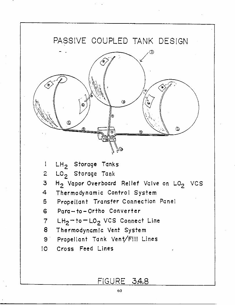
PASSIVE OOUPLED TANK
7/¢
DESIGN
®
C-
3
4
5
6
7
8
9
I0
LH 2 Storage Tanks
_'_2 ._,v,_ ,_,,_
H 2 Vapor Overboard Relief VQlve
Thermodynamic Control System
Prope[lant Transfer Connection
Para-- _o- Ortho Converter
LH2-to- LO 2 VCS Connect Line
Thermodynamic Vent System
Propellant Tank Vent/Fill Lines
Cross Feed Lines
on LO2
Panel
VCS
FIGURE 3.4,86O

encountered at the VCS. As it leaves the VCS, the hydrogen vapor then
passes through a para-ortho converter. This converter speeds up the
conversion of para-hydrogen (hydrogen with anti-parallel proton spins)
to ortho-hydrogen (hydrogen with parallel proton spins). This
conversion is an endothermic reaction and is used to absorb 15% of the
total heat l_ea_ in the system.
The above conversion is performed by the addition of a catalyst, such as
APACHI-I. The heat of conversion has a maximum of 400 J/g at 100
degrees K while an enthalpy change of 900 J/g gives a change in
temperature from 20 to 100 degrees K. Therefore this conversion can
reduce the temperature of the hydrogen vapor by 36 degrees K. The use
of APACHI-I would require about 100 grams of catalyst for each g/s of
hydrogen vapor flow.
After leaving the para-ortho converter, the vapor passes through the VCS
surrounding the LOX tank. A constraint is placed on the system such
that the hydrogen vapor flow rate through the VCS surrounding the LOX
tank is sufficient to intercept all heat leak to the LOX tank. The
hydrogen vapor is then vented through an overboard relief valve on the
LOX tank into the environment. A TCS and a TVS should control the flow
of hydrogen vapor through the vapor cooled shields, as well as the para-
ortho conversion. The TCS, TVS, and para-ortho unit should weigh
approximately 800 Ibs (363 kg) for the TAXI A version.
The VCS should be embedded in a two inch thick insulation blanket (see
Fig. 3.4.9)(based on a study at Ames Research Center and a Boeing
study). A study performed at NASA's Ames Research Center concludes that
for a single VCS the shield should be located at 0.35 times the
insulation thickness, or .7 inches (1.72 cm). The insulation blanket
will consist of foam insulation, multi-layer insulation, and Dacron net
spacers as described below°
The first layer of the blanket is an inner radiation shield. This
should consist of a .00033 inch (.0076 ram) thick layer of double
aluminized Kapton (DAK). .DAK is selected because it is a state-of-the-
art material and has been well tested. Double goldized Kapton provides
slightly higher performance, but is not considered to be as costeffective as DAK.
The second layer of the blanket consists of a 0.7 inch (1.78 cm) thick
layer of foam insulation. The foam insulation selected is Rohacell 31,
which is a polymethacrylimide, and has a density of 1.9 ib/ft 3 (30.0
kg/m_). This gives a lay-up density of .11 ib/ft 2 (.54 kg/ma). It is
selected because it exhibits similar properties as all other available
insulation materials, yet has a lower density and is easier to apply.
This insulation is applied in cut out layers which are staggered to
reduce heat leak through the seams (see Fig. 3.4.10). This allows the
insulation sections to be easily replaced, as opposed to spray-on
insulation.
A Dacron net spacer is then placed between the foam insulation and the
VCS. This helps to reduce layer to layer heat transfer.
61

- MLI/FOAM INSULATION BLANKET
I
2
3,_54
6
7
Inner Radiation Shield : 0.00033 in. (0.0076 mm
Thick Double Aluminized KapfonFoam Insulafion : 0.70 in ( !.7"78 cm ) Thick
Rohacell 31 Foam [nsulafion
Dacron Nef Spacers
Vapor L, uoleu _fllelu k v_,_ J v.ww_),- in
( 0.130 ram) Thick AI Sheet Bonded ToA 0,252 in ( 0.64 cm )
HoneycombDouble Aluminized Kapfon
(3.302_ mm) ThickLaminated Double.
And Dacron ScrimThick
Thick AI
1.30 i n
Alumined Kap'ro nO.OOI in (O.025mm)
FIGURE 5 _9
62

0
63

The VCS is made of a .00512 inch (0.130 mm) thick aluminum sheet bonded
to a .2520 inch (0.640 cm) thick aluminum honeycomb. The combination
has a lay-up density of .237 Ib/ft 2 (.57 kg/m2). A Dacron spacer is
then placed between the VCS and the next layer of insulation.
The MLI consists of 1.30 inches (3.302 cm) of DAK. There are 60 layers
of DAK per inch. The DAK is applied as the foam insulation was applied,
in overlapping sections to reduce heat leak at the seams as well as give
greater ease in replacement (see Fig. 3.4.10).
Finally an outer radiation/reflective shield is applied. The shield
consists of a laminated DAK and Dacron Srim layer 0.001 inch (0.025 mm)
thick. The DAK layers, Dacron spacers, inner and outer shields, as well
as Velcro attachment tabs gives a density of 2.19 lb/ft 3 (35.1 kg/m 3)
for a lay-up density of .238 ib/ft 2 (1.16 kg/m2). This gives a total
blanket lay-up density of .463 lb/ft 2 (2.26 kg/m2).
Propellant Boiloff
For the TAXI B (LH2 tank diameter = 16.43 ft), the tank insulation
system proposed here is expected to yield a boiloff rate of
approximately 0.15 lbm LH2/hr per LH2 tank or a total of 14.4 lbm
LH2/day for four tanks. It is assumed that this boiloff rate can be
reduced to 75% of the stated value with 2020 technology. This will
yield a boiloff of 10.8 ib LH2 for four LH2 tanks. Because well over
75% of the propellants will be used during the first few days of the
trip, the maneuvering propellant needed for the propulsive maneuvers
during transfer from the Cycling Ship to the planets may be stored in
one LH2 tank. This will reduce boiloff during long trips when the TAXI
is docked at the Cycling Ship. During the 146 days enroute to Mars
system, the boiloff will be 394.2 ibm which represents about I I/3
percent of the total initial LH2 carried by the TAXI. This loss of
propellant can be compensated by simply increasing the fuel reserve; as
the tanks are sized for the return trip from Mars to Earth, they can
easily accommodate extra fuel enroute to Mars. Enroute back to Earth
(636 days), the boiloff may reach 1717.2 ib or 4.2 percent of the
initial LH2 (40,814.3 ibm) carried by the TAXI. Perhaps the simplest
way to compensate for such a loss of the propellant is to adopt the
following scheme. Each TAXI departing from LEO would carry additional
2000-3000 lbm of LH2 and deposit it in Cycling Ship tanks while enroute
to Mars. This propellant would then be supplied to the Earth bound TAXI
shortly before the latter leaves the Cycling Ship.
Significant reductions in heat leaks could be achieved with specially
designed low leak support struts made of composite materials with high
strength and low thermal conductivity, and orbital disconnect struts
which connect to the tank structure only during periods of high
structural loading and should be considered in the future. During
vehicle transit the orientation of the vehicle to the sun will also be
critical in order to allow the minimum possible tank area to be exposed
to the solar flux.
Additional situations exist in which the vehicle is subjected to higher
than normal heat flux. The most important of these is the heating
during aerobraking maneuvers. It is estimated that this maneuver will
64

result in a worse case heating of 5 watts/cm 2 of exposed tank area.However this heating condition will only exist for a maximumof 150seconds and will be mostly radiated heat energy. Becausewe can expectthat the reflective outer shielding will reflect well over half the heatflux, and dueto the limited duration of the heating, we can expect thatthe increase_ boiloff rate can be easily accounted for with propellantreserves. Additionally, problems will be experienced in LEOand Marsorbit due to albedo effects from solar reflections on the surface of theEarth and Mars. This problem will also require caref-ul.vehicleorientation to help keep heat flux to the tanks to a minimum.
Propellant Transfer Systems
Initial requirements of the propellant transfer system are that thesystem must offer reasonable transfer times, low system weight, andsimplified operation. The system must also be adaptable to a number ofdifferent environments as it will be necessary to transfer fuel fromorbital tankers in the Earth-Moon and Mars-Phobos systems as well as toand from the cycling vehicle.
Attached and tethered depots were considered and a tethered system isselected because it meets the above requirements. The first advantageof the tethered system is that it settles fluid. This allows for anEarth-like environment where the liquid is over an outlet and the vaporis over a vent so that operations can be performed as normal with thetanks coupled together and continuously vented during fill (see Figs.3.4.8 and 3.4.11). A propellant transfer connection panel connectingthe two sets of 3 tanks is located next to the LOXtank in each tankset. This connection panel has quick-disconnect line connectors withlines for both vent and fill operations, as well as cross feed lines toconnect to the tank set fill systems. This eliminates the need for=_e=_ n_q_l_ _,_n_l and drivin_ svstems as well as storage forpressurizing gases. The tether also allows for separation between thevehicles to protect from contamination and explosive hazards (Kroll,1985 and 1986). Furthermore, if performed correctly, tether operationscould reduce delta-V requirements for subsequent operations whenoperating between the TAXI vehicle and an orbital tanker (Carroll,1985)(see Fig. 3.4.12).
In zero-g loading conditions, as in the case of the attached depot,fluid location in the propellant tanks becomesuncertain and thereforerequires some means to prevent gas pockets from interfering with
propellant extraction. Attached depots must therefore achieve fluid
settling through positive expulsion methods. Positive expulsion is
achieved through the use of movable metal and elastomer diaphrams and
pistons as well as pressurant gases. These systems add weight to
tankage and require that pressurant gases be available wherever a
propellant transfer is to take place. This adds a substantial weight
penalty and complicates the propellant transfer system (Huzel, 1971).
As attached propellant transfer techniques will be necessary if
refueling is performed at the cyclic vehicle, pressurizing systems will
have to be made available on the cyclic craft itself. The TAXI vehicle
will not be equipped with propellant driving pressurization systems.
65

OFF-LOADING PROPELLANT
FROM TAXI VEHICLE
i
Vents
__K r Iv
'ZVent Line
evI?r Tefherluid Line
TC S_If _
Pump
ON-LOADING
TO TAXI
PROPELLANT
VEHIOLE
t TCS! , TCSI
Venfs
" /
_ /_ Lvent Line f/
I - v I / z Kevlar Tefher Pump
-Spray Bars / . .....z__ FIula uzne
FIGURE 3.4.._ I
66

o, ° /
0 --_
oo
o9 \ / # o0
m _ _/
/
/
/
/
67

A problem that tethered refueling does have is that of keeping vapor
from dipping into the outlet due to suction from propellant outflow.
This "suction dip" phenomena becomes the limiting factor in flow rate
during refueling. The flow of propellant must be stopped before the°
vapor reaches the outlet to avoid problems in the propellant feed
system. T_is can cause a large residual propellant mass to be left in
the tanks. Tether lengths versus LH2 tank diameter, transfer times for
various tether lengths, tank sizes and mass flow rates for various
suction dip heights have been calculated for both LH2 and LOX assuming
an angular velocity of the tank combinations of .2 rpms. LH2 cases are
shown as they are the limiting cases due to liquid properties (Figs.
3.4.13 and 3.4.14). It is concluded from these calculations that
reasonable transfer times with residuals as low as i% can be achieved by
varying mass flow rate (Kroll, 1985).
The lines used for tethering the propellant transfer facilities should
be made of high strength Kevlar or other high strength polymers and
could be housed on large reels onboard the cyclic vehicle (Kroll, 1986
and NASA N85-17006, 1985).
While conducting propellant transfer operations from a storage facility
or tanker craft to the TAXI vehicle it will be necessary to "chilldown"
the propellant tank walls before pumping. This is accomplished by
successively spraying liquid propellant into the tank, and allowing the
propellant to vaporize and cool the tank's walls, and then immediately
venting it into space (Kroll, 1985). The process will be repeated until
the receiving tank's walls are at a sufficiently low temperature to
accept the liquid propellant (see Figure 3.4.15).
68

I.
EF5
i. n
a
iC _
I.__=
q'l,o5
__I_-
Ui_-
6D
F--4--,'
I-- o0CO
t,I
69

--_'
.r--@
!
._J
.4-
L£.
7O

TANK THERMODYNAMIOS
DURING OHILLDOWN
20._,--C harge_,-_Ven _-_
Pressure I
. IO-(ps_a)
.
Time
700,
600-
Temp.500
400C°R)
300
2OO
100
I0 Time
Chilldown
Complefe
FIGURE 3.4.15
71

REFERENCES
"Advanced Propulsion Systems Concepts for Orbital Transfer Study", Vol. I, Seattle:Boeing Aerospace Co., 1981.
BiaUa, P., P.. R.izzo, J. Schuster, C. Torre, and K. Whitehead, "Orbital Transfer SystemsStudies & Technologies," December 1986, General Dynamics Aerospace Division.
Blount, D. H. and J. L. Tuttle, Perfect Bell Nozzle Parametric and Optimization Curves,NASA Reference Publication 1104, 1983.
Brown, Norman, "Mars Transit Vehicle Thermal Protection System: Issues, Options, andTrades," NASA-MSFC.
Carroll, Joseph A., "Guidebook for Analysis of Tether Applications," Martin MariettaCorporation, March 1985, Contract no. RH4-394049.
Eagle Engineering, Manned Mars Mission Study Group, "Conceptual Sketches for anAggressive Man in Space Program," November 1985, NASA Contract no. NAS9-17317.
Eberhardt, Ralph N.,"Propellant Transfer:. Attached Depot," Martin Marietta DenverAerospace, NASA Report no.N85-17005.
Eqorov, P. R., "Fuels for Rocket Engines," NASA Report N67-25155.
Paget, Maxime A., "The Space Shuttle," The Seace Shuttle--Its Current Status andFuture lmDact.
General Dynamics Convair Division, "Definition of Technology Development Missions
For Early Space Station-Orbital Transfer Vehicle," San Diego, California, Reportno. GDC-SP-83-052: Contract no. NAS 8-35039.
Hastings, Leon J., "Cryogenic Fluid Transfer - Orbital Transfer Vehicle," Marshall SpaceFlight Center, NASA Report no. N83-11197.
Hill, P. G., and C. R. Peterson, Mechanics and ThermDdvnami¢_ of Prol_uision, Reading,Mass., Addison-Wesley, 1970.
Huzel, Dieter K., D. H. Huang, Desi_,n of Liouid Proeellant Rocket Entines, NASA SP-125, Washington, D.C., 1971.
Kittel, Peter, "Passive Storage Technologies," NASA Report no. N85-17003.
Klein, Gail A., "Active Cooling Requirements for Propellant Storage," NASA JetPropulsions Laboratory, NASA Report no. N85-17004.
Kramer, T. J., E. W. Brogren, B. L. Siegel, "Evaluation of Propellant Tank Insulation
Concepts For Low-Thrust Chemical Propulsion Systems - Executive Summary,"Boeing Aerospace Company, Contract no. NAS3-22824.
Kroll, Ken,"U.S. Gravity Utilization of Tethers Activity," Johnson Space Center, NASAReport no. N86-28417.
72

Kroll, K., "Propellant Transfer - Tethered Depot," NASA Johnson Space Center, NASAReport no. N85-17006 -- 85-109C.
Lewis Research Center, "Storageand Handling Of Cryogenic Fluids,"NASA Report no.N66-33674.
Lindstrom, Robert E. and Judson A. Lovingood, "Status of Space Shuttle External Tank,Solid Rocket Boosters, and Main Engine," The Soace Shuttle--Its Current Statusand Future Impact.
NASA Space Shuttle News Reference, NASA Press Release Kit, Fourth Space ShuttleMission, NASA, 1982.
Pederson, Erik S., Nuclear Energy in Soace, New Jersey: Prentice-Hall, Inc., 1964.
Perini, L. L., "Thermochemical Code for a Personal Computer', Johns Hopkins AppliedPhysics Laboratory, 1986.
Peters, Dr. Robert L., DesiEn of Lieuid. Solid. and Hybrid Rocket.% Hayden BookCompany, Inc., New York, 1965.
Quentmeyer, R. J., H. J. Kesper, and J. M. Kazeroff, "Investigation of the Effect ofCeramic Coatings on Rocket Thrust Chamber Life', NASA Lewis ResearchCenter, 1986.
Rysavy, Gordon, Thomas G. Rogers, Michael L. Davis, Robert K. Allgeier Jr.,"The
Development of Cryogenic Storage Systems for Space Flight," 1970 NASA,Washington, D.C.
Sanchini, D. J. and H. I. Colbo, "Space Shuttle Main Engine Development," The SuaceShuttle--Its Current Status and Future lmeact.
Sarner, Stanley F., Prooellant Chemistry, Reinhold Publishing Corporation, New York,1966.
"Structural Integrity and Durability for the Space Shuttle Main Engine', NASA-TM-87280.
Stuhlinger, E. A., "Ion Propulsion for Space Flight," McGraw-Hill, New York, 1964.
Sutton, G. P., Rocket Prooulsion F,lcmcnts, New York, John Wiley & Sons, 1956, 1976.
Walburn, Allen B., "Development of a Reusable Flightweight Cryogenic Storage System,"AIAA Paper No. 74-726.
Warren, Francis A., Rocket Pronellants,Reinhold Publishing Corporation, New York,1958.
73

4. Aerobrake Design
As part of the scenario for the Manned Mars Mission, aerobraking will be used todecrease the energy of the TAXI at both Earth and Mars. Any configuration
considered for.t.he TAXI must therefore be able to achieve the required velocitychanges without exceeding heating or deceleration limits. Since 1961, there has been
interest in finding a way to accomplish orbital and velocity changes using aerobeakingsystems (Walberg, 1982). The drive behind this is the reduction in the amount of
weight, namely fuel, that has to be lifted from the earth's surface. For instance, 10 kgmust be lifted from earth to place one kilogram in orbit at Mars.
Because the vehicle will be space-based and manned, a design with high reliability thatneeds little or no refurbishment is desired. Therefore, ablative thermal protectionsystems (TPS) are undesirable, whereas a flexible, reusable aerobrake structure isdesirable.
4._! Aerobrak¢ Tyl_e_ _9nsidered
Three classifications of aerobraked vehicles have been designated in the literature. 4 The
first of these is a variable area type, whose ability to adjust drag is limited by themaximum and minimum brake areas. This type has no lateral plane control: it cannotchange the angle of its orbit around the planet.
The second type is a biconic craft with fixed area and variable angle of attack (see
figure 4.1.1). A low volumetric efficiency characterizes this kind of vehicle, making itsomewhat unsuitable for our project.
The third type considered consists of a large fixed area shield, with a fixed angle ofattack and variable bank angle. This vehicle flies a deceleration profile indirectly, withthe lift vector moving the craft to a higher or lower density regime to adjust the drag.
A moderate to high L/D aeromaneuvering vehicle was dismissed as a possibility. 3 Itweighsmuch more than other designs for a given payload volume, is more difficult toconstruct, and its high ballistic coefficient necessitates a heavier heat shield.
Based on mission requirements, three aerobrakes were examined: a symmetrical aeroshell(figure 4.1.2), an extendable web mesh behind or in front of the ship (figure 4.1.3), and
a raked-off elliptical cone (figure 4.1.4). Blunt symmetric aeroshells have been ._tudiedextensively, and were presented for the NASA Manned Mars Mission Report." Thelatter two designs were investigated in more detail.
The webbing design has two possible configurations (Ehricke). The first consists of arigid outer frame with ribbons of Teflon-covered steel mounted in tension between the
sides of the frame. This configuration weighs more than the second design which issimply a mesh of ribbons. The cables are held in tension during aerobraking byforward=running cables and aerodynamic forces. These cables would be highlysusceptible to flutter.
74
s• •

_ICONIC LIFTI_;J CRAr-_
FIGURE 4.1.1
S_-T RIC AEROSHIELD
symmetric aeroshield
i
crew module
FIGURE _.I.2
75

FLEXIBLE MESH BRAKE
crew module- -
englne
flexible mesh
FIGURE 4. I. 3
RAKED-0FF ELLIPTIC CONE
crew module
fuel tanks
engine /
FIGURE 4.1.4
?6

The advantages of this type of design are the ability to radiate heat from both the inner
and outer surfaces, very low weight, variable brake deployment (allowing adjustment todrag requirements), and the fact that the use of large, high-drag surfaces reduces theneed to enter high density atmospheric regions for velocity reduction. Unfortunately,literature searches revealed only two papers which examined this design; they pointedout many technological barriers to a brake of this type, leaving more questions than thislevel of investigation could answer.
The following section describes the chosen configuration, an ellipsoidally-blunted raked-off elliptic cone (EBROEC), mounted in front of the crew
module, payload and engine systems. Next, trajectory simulations and
aerothermodynamic analysis of the aerobrake (sections 4.3 and 4.4) are
discussed followed by presentation of a preliminary structural design of theaerobrake and its supporting structure (sections 4.5 and 4.6). All these
sections refer to the TAXI version A. The main design paremeters of the
aerobrake for the TAXI versions B and C are given at the end of thischapter.
.1.2 Aer0shi¢ld (_eQmetrv Anai_,_i_
The heat shield designed for the TAXI is basically a modified elliptic cone, with acoordinate system setup which has its origin at the vertex of the cone(figure 4.2.1).The half-angle along any given meridional cut (q)=constant) is called 0. Specifically,
the half-angle in the x-y plane is designated 0,, and in the x-z plane 0u . From theseangles the cone ellipticity is detained as _=tan 0x) /tan0x, A reference plane is chosennormal to the x-y plane and raked at an angle 8 with respect to the x-z plane. The
requirement that the intersection of the cone and the reference plane be a circle fo_easier shape definition determines the angle 0,, , and hence E, for a given 8 and 0,, ."For our selection of 0,) =60 degrees, we will have a cone ellipticity of 0.9377 in orderto have a circle as a base.
To reduce nose heating, the nose is replaced with an ellipsoid which is tangent to the
cone at every point. The shape of the ellipsoid is determined by the ellipticity eb • Theregion of the elliptic cone between the ellipsoid and the reference circle is a function ofq), the angle about the x-axis describing the y-z location, and the equation for theelliptic cone.
In each plane of constant _0, a circular skirt of radius R is fit to the reference circle.
This will reduce the trailing-edge heat flux and provide greater dynamic stability. The
center of rotation for the arc (Xos,ros) is a function of (l). The rear of the body isdefined by a base plane parallel to the reference plane. The angular extent x of thecircular arc defines the distance between the reference plane and the base plane. Notethat the resulting base plane is no longer a perfect circle. A shape of this form is then
completely characterized by specifying 8 0,y , _ , R, and
The conical afterbody is raked off at angle 8 to provide lift at zero angle of attack. Thebase of the heat shield in the rake plane is circular for packaging efficiency and to easethe joining of the shield and payload. The heat shielding under consideration wouldhave a nominal diameter of 120 ft (36.5 m).
With a suitably placed center of gravity, this design produces lift and trim at zero angle
of attack. One other advantage of high rake and cone angles is that it permits a greaterlatitude in the placement of the center of gravity; i.e. the c.g. can be placed farther aft.
77

G EONh-T RIC DERI V:_71 ON
Y
Z
FIGURE 4.2.1
FIGURE 4.2.2
78PAt_i__-._F_._IdDl_.J_ B_K NLY.e FII.,I[_D.

Our currentdesign utilizesa rake angle of 80 degrees. For a given rake angle there will
be an optimal radius of curvature,Ro, at the nose in order to reduce maximum heat flux.This radius is a measure of the bluntnessof the ellipsoidat the Newtonian stagnation
point in the x-y (pitch)plane. Larger valuesof R o are possiblefor a given 5 and 0x,by increasing the nose ellipticityE_. As e_ increasesthe nose becomes flatter. An
optimum e_ i_ possiblefrom a standpointof a uniform heat flux on the blunt surface,
and will be discussed further in section4.4.In thisdesign we will use an ellipticitye_of 2.0,resultingin a moderately flatnose with low heating ratesI.
The shape of the heat shieldhas been computed and isshown in figures4.2.2and 4.4.1.
Itsmain advantage is itsliftat zero angle of attackrelativeto itsx-axis. See the paperby Cheatwood, et al.for a complete geometricalderivationof the shield.
4.3 Aerobrake Traiector3,
4.3.1 Introduction
Aerobraking uses the planet's atmosphere to dissipate energy to affect orbital changes.The velocity decrement is accomplished through the aerodynamic properties of thevehicle, mainly drag. A plane change is desirable, but not a requirement. The vehiclein this design is classified as one with a fixed area and fixed angle of attack withvariable bank angle and roll rate (Dauro, 1979). This means that lift moves the craft to
higher and lower density regions to keep the ship on the design deceleration profile.This differs from a direct profile, which would be flown by changing angle of attack,thus changing lift and drag.
The type of trajectory to be flown is a skip trajectory, defined by Eggars and Allen as
having three parts: atmospheric entry, maneuvers, and atmospheric ejection. Figure4.3.1 is a sketch of the flight path. Also included in the sketch is a diagram of theforces acting on the vehicle throughout the passage. The equations of motion for this
ship are written in terms of coordinates parallel and perpendicular to the flight path.The resulting equations are generally nonlinear, second order differential equationswhich cannot be easily integrated (Chapman, 1957). The simplified equations were
derived by Miele, who assumed a flat, nonrotating planet. He further simplified theequations by assuming D/W >> 1, L/W >> 1, and flight in two dimensions. Theseequations will be integrated numerically in time so that the flight profile can bedetermined. After a description of the mission and the computer programs, the results
of the programs will be discussed in terms of whether or not aerobraking can accomplishthe required velocity changes.
4.3.2 Mission Requirements
The entry state of the vehicle is important in determining whether or not the vehicle canachieve its mission. Dauro and Boobar defined the entry state by latitude, longitude,altitude, velocity azimuth, flight path angle, aerodynamic characteristics, and the ship'sphysical constraints, which include limits on aerodynamic heating, aerodynamic pressure,and deceleration. In order to achieve the required velocity decrement, the onlyparameter that may be varied is the flight path angle. Table 4.3.1 provides an overviewof the relevant parameters.
79

°\
\
A
4-:
v
I,-I
8O

Table 4.3.1 Physical Parameters (TAXI A)
Reference area, A
Vehicle mass at the beginning of the
aeroassisted_ maneuver near Earth, MBA M
CD
Ballistic coefficient MB/_/CDA
L/D
Maximum heating rate, qmax
Maximum acceleration
Initial inclination
11602.4 ft2 (1078 m2)
114,347 lbm (51,855 kg)
I.574
6.26 ibm/ft 2 (30.56 kg/m 2)
0.1526
30 W/cm 2
5g
23 deg.
Latitude, velocity, and velocity azimuth were prescribed by the orbital mechanics group.
At both Earth and Mars, the ship enters the atmosphere with its velocity vector at an
angle of 23 deg to the plane of the equator. In order to dock with the space station in
LEO, and Phobos orbit, the ship must be in the plane of the equator, so
that whatever plane change cannot be accomplished during the atmospheric pass will
have to be done by propulsion. Aerodynamic characteristics are calculated in section
4.4.1 using Simplified Newtonian Theory. The reference area is the area perpendicular
to the free stream. Nicalon, the flexible thermal protection material, defines the limit
on aerodynamic heating. The deceleration limit was imposed by the maximum that the
crew can be subjected to. The use of a low L/D and low ballistic coefficient makes
it possible to stay in the viscous region of the atmosphere, which keeps heating and
deceleration rates low since most of the aerobraking will occur near perigee (Dauro,1979, Walberg, 1982).
The exit state is defined by the same parameters as the entry state. The final velocity is
determined by the velocity change. The other parameters are important in determining
corrections needed beyond the atmosphere to place the ship in its final orbit.
4.3.3 Computer Programs
Computer programs simulate trajectories by using numerical techniques to integrate the
equations of motion. The accuracy of the simulation depends on the assumptions made
in the governing equations and the accuracy of the numerical method. Two programs,one simple and the other complex, were used. A simple model can
be run quickly and cheaply on a personal computer.
Simpli/ied
Using Miele's equations and the further assumption that density varies exponentially
with altitude, a FORTRAN code using Euler integration was written and run on an IBM
Personal Computer. The trajectory was purely ballistic, with no bank angle modulation.This means that the results will be the most severe that can be expected. The program
outputs velocity, acceleration, and altitude as funtions of time, as well as the magnitude
and point of maximum dynamic pressure. Heating rates were not determined within this
program; instead, a code that solved the Euler_ equations ]_or an axisymmetric shape was
used to solve for the heating rates at the perigee of the trajectory.
81

POST
The second simulation was the Program" to Optimize Simulated Trajectories, POST,
which was written at NASA Langley in 1971 and is updated continuously. The programcan be run for either 6 degrees of freedom (DOF), or 3 DOF. In 3 DOF it assumes that
the vehicle is a point mass, limiting its motion to vertical, forward, and lateraldirections. The program optimizes entry angle using heating ratesand decelerationas
limitingparameters. The trajectoryis controlledby bank angle, with rollsconsidered
instantaneous. POST outputs include velocity,altitude,acceleration,dynamic pressure,heating rate, and bank angle as functions of time. The heating rate is based on
Chapman's heat equation,which accounts for the incident convective heat on the shield.
Itdoes not account for the shield'sabilityto reflectincoming heat,nor does ittake into
account radiation,which may be important,especiallyat Mars.
4.3.4 Results of the Simulations
Both codes were run at Earth and Mars. Init!ally, POST was run at Mars because theacceleration and thermal environments were expected to be more severe. However, thisdid not appear to be the case when the simulationresultswere fullyanalyzed.
Earth
For the first pass at Earth, the ship will enter the atmosphere at 41393.6 ft/sec (12.62km/sec) requiring a loss of 6133.6 ft/sec (1.87 kin/see). Figures 4.3.2 through 4.3.4show the velocity, acceleration, and altitude from the PC simulation for three different
entry angles: -0.5, -1.0, and -1.5 deg. From figure 4.3.3 it is apparent that an entryangle close to -.75 deg should be chosen. This results in a maximum acceleration of 1 gwhich is well below the 6 g limit. The altitude plot shows that the craft will reachperigee still in the viscous region of the atmosphere.
POST, however, found -4 deg to be the best entry angle (Figure 4.3.5). A gamma higher
than -4 deg caused skipping into a hyperbolic orbit. The_ resulting maximum accelerationand heating rates are 3.5 g's acceleration and 20.5 W/cm" Fig. 4.3.6 & 4.3.7).
The second pass begins at a velocity of 35 686.4 ft/sec (10.88 km/sec). Figure 4.3.8
shows that an entry angle of approximately -1.25 deg. will result in thenecessary loss of 9184 ft/sec (2.80 km/sec). The associated values of
maximum acceleration, 1.84, and minimum altitude, 280,085 ft (85.37 km),
are shown in figures 4.3.9 and 4.3.10 respectively.
POST again required a steeper entry angle than the PC simulation to avoid skip-out to a
hyperbolic trajectory. The entry angle is about the same as for the first pass, -3.72 de_t,
(Figure 4.3_11), but the acceleration is higher, 4.0 g (Figure 4,3.12). The heating rate is14.5 W/cm '_ (Figure 4.3.13).
Mars
The results of the PC simulation at Mars reveal that an entry angle of -2.5 deg willenable the ship to lose 19 122.4 ft/sec (5.83 kin/see). However, it has been
calculated that at this entry angle the acceleration exceeds the 6 g limit. Withoutchecking the results against POST, this would lead to an erroneous conclusion that either_ne ship needs to be redesigned or rockets must be used.
82

POST required an entry angle less than -6.0 to avoid skipout to a hyperbolic trajectory ,and greater than -7.5 degrees to avoid impact with the planet. Figure 4.3.14 shows thatan entry angle of -6.5 is the optimum. These angles are much larger than those in the
PC simulation, yet the maximum acceleration is three Earth g's (fig. 4.3.15). This can beattributed to the control of the flight path through roll and the fact that POST integrates
the complete g_ver_ing equations. Figures 4.3.16 and 4.3.17 show a maximum hea_fngrate of 18.9 W/cm and a maximum dynamic pressure of 240 N/m _'. Both of thesevalues are below the upper limits.
The second pass at Mars was not simulated because of the small velocity decrementrequired.
4.3.5 Conclusions and Recommendations
In itspresent configurationthe ship can achieve allof the specifiedvelocitydecrements,
eliminatingthe need for propulsive maneuvers. Table 4.3.2 summarizes the resultsof
the trajectorysimulations. The passesat Earth do not present any problems in terms of
stresson the ship, crew, or modeling. Mars, however, requires more sophisticated
modeling. Because of the narrow entry corridor, complex adaptive controllawswill be
necessary,which was expected (Walberg, 1982). Because the ship will fly in the free
molecular and viscous regions of the atmosphere, degradation of L/D will have to betaken into account, and analysis of rarefied flow, which is difficultto simulate in
ground test facilities,must be improved. In further studies a better model of the
heating environment at Mars willbe required,and the 6DOF POST simulation should berun.
Table 4.3.2 Traiector¥ Summary
Earth Mars
Pass 1 Pass 2 Pass 1 Pass 2
Venter(kft/sec)delta-V(kft/sec)
Vexit(kft/sec)
iGammainitial(deg)nitial Inchnation(deg)
Plane Change(deg)Perigee Altitude(kft)
Passage Time(sec)Maximum Acceleration(g)
qmax (W/cm2)
43.33 35.69 33.886.13 9.18 7.81
35.19 26.50 16.07-4.0 -3.72 -6.5023.0 _ 23.0
1.12 2.0 6.65311.60 301.76 229.60130.0 247.0 160.0
3.52 4.06 2.9
20.5 14.50 18.9
16.07
2.0714.00
83

42
Velocity vsFirst Press
TTme
U.C
_o_@>
41
40
39
38
37
36
35
34
33
32
31
30
29I I I I I I
_'u --,S
0 200 4OO
lime (see)
FIG 4.3.2_.
Acceleration vs.F'irstF=oss
T'me
600
Cq
(U
@I
C0
_JUU
3.5
3
2.5
2
1.5
0.5
0
0I
200I
400
lime (see)FIG 4,3,3
600
84

"0
400
3go
3BO
370
360
350
340
330
320
310
300
2go
2BO
270
260
Altitude vs.First Pass
Time
l I I I l I
0 200 400
_me (sec)
FIGI 4.3.4
600
]_,I_lt_ PATH At;GLE
EARI'H AERO{_AKING. FIRST PASS
"1
-2
-J
¢
= /
4
-7
-41 _llllllll Illlllll
0 25
J
Illllllff!|lillif|| ililltill ffifififi ialiliif iffilill!ilifiilfi iililllil_ too 12_ I_ II_ 200 2_r._ 2_
llU£. #_
FIG. 4.3.5
85

4.5
4,0-
ACCEL. JLS-
ACCELERA_ TION
,10
2.5
2.0
1.5
1.0
:+.j,,,,0
i
/-\/
I!!111111 llllllllt
\llllllllli IIIIlI_T_I
2.5 50
FIGURE
73
4.3.6
I00
"t-_I-LI I I 11 II!1111
12-" I'.JO
TIME. sec
275000
2._000
¢IB000
2OOOOO
175000
IZSO_
100000 - /7_
/
EARTH
|
I iAEROBRAKING, FIRST PASS --
1 IHEAT ING RATE
0 _11111111 111111111 Illlllllll IIIIIIIIIi I|lllllll IIllllll I!1111
1'1M£. sec
FIGURE 4.3.7
86

34
Velocity vs TTmeSecond Poss
33
32
_ou..E
31
30
29
28
27
26
25
24
0] I
200 400
Time (sec)
FI G 4.3.8
2.6
Acceleration vs. T.TmeSecond P_ss
E0
°_
0
0
(J(J
2.4
2.2
2
1.8
1.6
1.4
1.2
1
0.8
0.6
0.4
0.2
0
0T f
200
Time (sec)
FIG 4.3.9
4.00 600
87

-.-,0
4-00
390
380
370
360
350
340
,330 -
320 -
310 -
300 -
290 -
280 -
270 -
260
0
Altitude vs. TimeSecond Pass
-I.5
I
200I I
400
Time (sec)
FIG 4.,5. I0
I
600
2
!
o
-!m
fJ
PATH ANGLgFLIGHT
If
//
- /
0 -4
=-S
=-4
==
-7=
4_lliiliim0
EARTH AEROBRAKING.
J
IIIIIIIIlllllllllll IIIIIII11 IIIIIIII! IIIIIIIIl:lllllllll
SECOND PASS_
IIIllllll! IIIIIIIII IIIIIIIII
17_ 2OO 2"_ 3SO2.5 _0 7:1 I00 12:b I_0
TIME. sec
FIGJRE. 4.3.11
88

5.0 -
ACCELE+{AT ION4.O r_ '
15
10 - ....
ACC_L. 2.sg*l 2.0
1.0 ,,
.5
0-_144"_11 llllll|tl lilllllll I|IIIIIII |IIIIIIII IIII'_'I_F'H44-LIJJ.
0 _ _0 7_ Ioo 12_ I_o 17s 2oo
TIME. s_
PIGUR_ 4.3.12
'mI175000
150000
12_
7_000
2_000
HEA_2 ING RATE
EARTH
m
m
m
m
- ylw
//
\
,,, IAEROE3RAKING, SECOND PASS
w
O _11111111 [lllllllll Illllllll !lllllllll IIlllllll] IIlllllli Illllllll IIIllllll IIIlllll'l !1111111130 '_ _0 "_ tOO t25 tSO 11_ 3130 2_1+ 2,50
TIME, sec
FIGURE 4.3.i3
89

FLIGHT PATH APlGLE
=
D --
=
-|
-!
-4
-7
.4_lllttttl0
//
//
/
,.,,,-/
ff
u,_5 AEROBRAKING --
tl|tllit| lilt|till II111lill itlIlilit |iti|tll! IiIIIItl| ;IIIllIIIlllIIIl|III IItlilIIq
TIME. se¢
FIGURE 4.3.14
_CIL.
g'|
i|
&O
;.s
7.0
IL',
4.0
s,$
_O
4'1 /4,0 ,.
/L
.lO
2.0
t.|
t.O
.$
0 ;,H*.**
//
\
IIIIIIIII |llllllil
\\\
\\
ACCELERAT ION --
Illl}lltl IIlllllll Ilillllil _'_'l"r_*ii Illil|Jil 111111111 IIIlillla
I oo I _s I_O I IS 200 Z_ 2SO
111d(, sire
z2 =o 7_
FIGURE 4.3.15
9O

HEATING RATE
2_
325000 -
2(_000 -
17!_00 F
/
OMIIJIIIII0
AEROBRAKING
\
IIIIIIIII] I lllll|lll _ "TT1"1'9_ I ! lllllllll!
2.,5 _ 75 I O0 12_ 150 1731 2{X}
",,."MAI:L"5
• ii
LIIIIIIII
TIUE. sec
FIGURE 4.3.16
qlB
N/m 2
218
250
225
2O0
15017Si ' /
12S100
I I
DYNAMIC PRESSUREI I,,
MARS AEROBRAKINGi
\75
tt-t.kLU I I IIIIIIIll0 Z._ 75 t O0 t 2:5
TIME. secFIGURE 4.3.]7
15o 175 3oo

4.3.6 References
I. Boobar, M. G., Chapel, F. G., and Repic, E. M., "Aerobraking as a Potential PlanetaryCapture Mod.e," Journal of Spacecraft and Rockets, Vol 5, Aug 1968, pp 921=926.
2. Chapman, D. R., "An Approximate Analytical Method for Studying Entry IntoPlanetary Atmospheres," NACA TN 4276, 1956.
3. Dauro, V. A., "Aerobraking," Marshall Space Flight Center, 1979.
4. Eggars, A. J., Allen, H. J., Neice, S. E., "A Comparative Analysis of the Performanceof Long=Range Hypervelocity Vehicles," NACA TH 4046, 1957.
5. Loh, W. H. T., "Reentry and Planetary Physics and Technology, Vol. II," Springer-Verlag, New York, Inc., 1968.
6. Miele, A., ThpQrv of Flight Mechani¢_, Vol.I, Addison-Wesley Publishing Company,Inc., Reading, Massachusetts, 1962, pp 301-307.
7. Walberg, G. D., "A Survey of Aeroassisted Orbit Transfer," AIAA 82-1378.
92

4.4 AerothermodTnami¢ .-%nalysi_
In evaluating the heating and pressure characteristics of a hypersonic re-entry vehicleseveral methods may be used. Of these, Newtonian or modified Newtonian methods areuseful in approximating Cp's and aerodynamic coefficients. Also, Euler codes are used
to evaluate the region behind the bow shock and are coupled with either integral orfinite diffef'ence boundary layer solutions.
The region aft of the shock is generally transonic with the shield being fully wetted with
subsonic flow. When using blunt, low L/D shield configurations, a skirt is usuallyemployed on the out=flow edges to ensure supersonic flow leaving the shield. This will
help diminish the thickness of the viscous shear layer in the wake region, thus, creatinga larger zone of protection and lower heating behind the shield.
A pressure, temperature, and heating analysis is presented that is coupled with thetrajectory maximum loading conditions. A Simple Newtonian meet'toot is usea co esca_lisn
the Cp distribution, and aerodynamic characteristics of the shield. An axisymmetricEuler and Integral Boundary Layer solution is employed on a cross=section of the shield
in order to establish the stagnation temperature, pressure, and heating on the shield.
4.4.1 Aerodynamics
Simple Newtonian Theory offers a useful approximation for surface pressgre distributionin hypersonic flows. The pressure coefficient, Cp, is calculated by 2"sin'0, where 0 isthe angle of the surface to the free stream direction (Figure 4.4.1). Figure 4.4.2 showsthe pressure coefficient distribution over the shield surface at zero angle of attack. Thisdistribution is used in a later section to develop the support structure. By varying theshield's orientation to the flow and integrating pressures over the surface, the shield'saerodynamic coefficients are computed.
Reference Area (area projected on y-z plane):A = 11602.4 ft 2 (1078 m2)
Reference Diameter: (the circular projection in Fig. 4.2.1):D ,, 115 ft (35.1 m).
The total shield area is 14090 ft '_ (1310 m2)
Calculated values at a -0:
CD_ = 1.5743 C L = 0.2402L/D = 0.1526 C M *, -0.2854
C L (_ - =0.01924/deg C D _ : 0.01263/degC M (_ *, -0.00783/deg Cy e -0.00825/deg
C N _ ,, 0.00617/deg CZ a *" -0.000081/deg
The coefficient curve slopes listed by Mayo et al for a shield without a skirt are lower,revealing the increased stability due to the skirt.
93

FLIGHT GEOblET RY
Y
Z
X
_- reference area
D - 115 ft (35.1 m)
\\\\\
I
8.68
line of action of forces
- stable C. G. locations
FIGURE 4.4.i
94

Y
I.SI
Cp [_ISTRIBUTION ( 5YI'_E.TR_C AI_0UT
I _1,
_'-_ SCALE
TME Y-AX IS
FIGURE 4.4.2
95

Alpha is defined in Figure 4.4.1. Aerodynamic coefficients are plottedvs _ in Fig. 4.4.3. Note, however, that CM is referenced to the vertexof the cone, not the C.G.
The positio_ qf the line of zero moment(C.G. position line) is found bydividing CM by CD, and its slope is given by tan e = CL/C D (Figure
4.4.1).
4.4.2 Numerical Results
Upon completion of the trajectory calculations, the point of maximum
heating for Earth was determined to occur at an altitude of 280,000 ft
(85,366 m). The corresponding flight regime is specified by the
following quantities:
P - 0.38717 N/m 2 M - 41.87= =
T = 180.65 deg K V = 11280.4 m/s= =
O= = 7.468 E-6 kg/m 3 a® = 269.45 m/s
A numerical axisymmetric solution is set up using integral boundary
layer equations. A slice of the shield through the stagnation point
(Figure 4.4.4) was chosen to give a good representation of the shield
behavior and was used to create a numerical grid for calculations
(Figure 4.4.5). The shield was tested for thicknesses of 0.5 to I .5
inches and plots of pressure, temperature, and heating were developed.
For the encountered Mach number of 41.87, the stagnation point pressure
rise P/P= (Figure 4.4.6) is about 2300, which drops to 1800 near the
shield edge. CPmax is 1.874 with a dynamic pressure of 475.1N/m 2.
The heat transfer (Figure 4.4.7) will be mostly convective for the
altitude and shield parameters involved. At the stagnation point q is
11.27 W/cm 2 convective heat flux. The heat transfer drops to 9.01W/cm 2
towards the shield edge. An expected hump occurs near S of 22 m where
the flow accelerates over the edge (S = distance along the surface from
the stagnation point). The heat conducted through the surface can now
be calculated. The shield surface temperature reaches a stagnation
value of 1249 deg K and stays nearly constant until the boundary is
reached. Similarly, the backface temperature also stays constant along
the surface. Small discontinuities arise near the corner of the shield.
The effect of shield thickness on pressure, heat transfer, and outside
wall temperature is negligible (Figs. 4.4.8-4.4.10); however, its effect
on inside wall temperature is significant (Figure 4.4.1). Since the
graphite polymide aerobrake support structure cannot endure temperatures
exceeding 600 deg K, the backface temperature must be kept moderate.
For Earth, a 0.5 inch thick shield would accomplish the required
protection; however, since there remains uncertainty about Mars
environment, a 1.0 inch shield is selected. The backface stagnation
temperatures are 541.3, 461.1, 418.8 deg K for 0.5, 1.0, and 1.5
inches, respectively.
96

©
6O
0
O9©
o --
O9
©
L.)0L_
0c-
O
©
0(->.,
-00L_
©<(
/ /
/
©c_
0
- 0
n
<_
E
o
o
o_"ocO
<I
"t'-
(,.)
13
'W"
L._r"r-'
L
_ue!o!j.j._oo s_ouXpo4av
97

PLANE. F0E NU_,IERICAL CALCULATIONS
FIGURE 4.4.4
98

GRiD
E
100
90
8O
7O
6O
5O
4O
3O
2O
10
0
0 10 2O 3O 4O
FIGURE 4.4.5
99

P
Wlm 2
Z3UU
2OOO
1500
IOO0
5OO
0 5
SURFACE125000
100000
75000
50000
SURFACE PRESSURE
25000
Math 41.87
10 15 20 25 30
HEAT TRANSFER (t = 1.0in)
S,m
' I I I I I
0 5 10 15 20 25 30
FIG. 4.4.6
FIG. 4.4.7
i0o

T,°K
I_00
1200
go0
600
300
0
SURFACE TEMPERATURE(t = 0.5in)
Outside wall M = 41.87
Inside wall ""-..
S,m
' I ' I ' I i I
0 5 10 15 20 25 30
FIG. 4.4.8
T,°K
1500
1200
900
600
300
SURFACE TEMPERATURE
Outside wall
(t
Inside wall """-..
0S_m
I ' I ' I I I
0 5 10 15 20 25 30
FIG. 4.4.9
lOt

T,°K
T,°K
1500
1200
900
600
300
0
SURFACE TEMPERATURE(t = 1.5in)
Outside wall M = 41.87
Inside wall
0
S,m
I ! I I I
5 10 15 20 25 3O
550
525
50O
475
450
42s
400
INSIDE WALL TEMP v sWALL THICKNESS
Math 41.87
t,in
0.50 0.75 1.00 1.25 1.50
FIG.
FIG.
4.4.10
4.4.11
102

4.4.5 References
1. Weilmuenster, K. James and Hamilton, H. Harris II. "A Comparison of Computedand Experimental Surface Pressure and Heating on 70 Degree Sphere Cones at Angles ofAttack to 20 Degrees." AIAA Paper 86-0567, 1986.
o
2. Hamilton, H. Harris II and Weilmuenster, K. James. "Calculation of Convective
Heating on Proposed Aeroassist Flight Experiment Vehicle." AIAA Paper 86-1308, 1986.
3. Menees, Gene P., et. al. "Aerothermodynamic Heating Analysis of Aerobraking andAeromaneuvering Orbital Transfer Vehicles." AIAA Paper 84=1711, 1984.
4. Menees, Gene P., Chul Park, and John F. Wilson. "Design and Performance Analysisof a Conical Aerobrake Orbital Transfer Vehicle Concept." AIAA Paper 84-0410, 1984.
5. DeJarnette, F. R., et. al. "A Review of Some Approximate Methods Used inAerodynamic Heating Analyses." AIAA Paper 85-0906, 1985.
6. Scott, Carl D., Robert C. Ried, et. al. "An AO.TV Aeroheating and ThermalProtection Study." AIAA Paper 84= 1710, 1984.
7. Zoby, E.V., et. al. "Approximate Convective=Heating Equations for HypersonicFlows." AIAA Paper 79=1078, 1979,
8. Menees, Gene P. "Thermal Protection Requirements for Near-Earth AeroassistedOrbital Transfer Vehicle Missions." AIAA Paper 83-0919, 1983.
9. Scott, Carl D., et al., "An AOTV Aeroheating and Thermal Protection Study", AIAA-84-1710.
I0. Cheatwood, F.M., et. al., "Geometrical Description for a Proposed Aeroassist FlightExperiment Vehicle', NASA Technical Memorandum 87714, July, 1986.
11. Letts, W. R.," Aeroassisted Orbital Transfer Mission Evaluation", AIAA-82-1380.
12. Walberg, G.D., "A Review of Aeroassisted Orbit Transfer',AIAA-82-1378.
13. Menees, G.P., "Thermal-Protection Requirements for Near Earth AeroassistedOrbital=Transfer Vehicle Missions', AIAA-83= 1513.
14. Mayo, E.E., et. al., "Newtonian Aerodynamics for Blunted Raked-off CircularCones and Raked-off Elliptical Cones", NASA Technical Note D=26241
15. Duke, M.B., ed.,"Manned Mars Missions',Working Group Summary Report, NASA,
May 1986.
16. Pitts,W.C. and Murbach, M.S., "Thermal Design of AOTV Heat Shields for a
Conical Drag Brake',AIAA-85=I052.
17. Pitts, W.C. and Murbach, M.S., "Thermal Response of an Aeroassisted Orbital-transfer Vehicle with a Conical Drag Brake', AIAA-84-1712.
18. Finch, T.W., "Aerodynamic Braking Trajectories for Mars Orbit Attainment',AIAA=Preprint-64=478.12. Regan, Frank J.,g¢-Entrv Vehicle Dynamics, AIAAEducation Series, AIAA Inc., 1984, pp. 219-234.
103

4.5 Aerobrake Structure
The aeroshield supporting structure is designed to be the main load carrying
element of the TAXI. Three major loads, aerobraking, thrusting, and
inertial, are supported and transferred throughout the vehicle. Some of the
design criteria are minimum weight, ease of assembly, ease of integration
w_th other 2omponents, and support of the complex geometry of the aerobrakesurface. The _tructure itself is composed of two distinct assemblies. The
first is the 3 dimensional truss structure (Fig. 4.5.1) which bears and
distributes the forces. The second, the ribbing (Fig. 4.5.2) which defines
the shape of the insulation and transfers the aerobraking pressure loads to
the truss structure. The ribbing is attached to the truss network at the
lower 32 node points of the truss network (Fig. 4.5.3). The tanks, engine
mounts, payload and crew module all have their truss work attached to node
points of the truss structure (Fig. 4.5.3). The weights and moments of this
design are given in Table 4.5.1.
4.5.1 Truss Selection
A few alternate truss structures were considered but were rejected for various reasons.
A radial truss network (Figure 4.5.4) was refused on two points. The nature of a radial
design made a high density of supports near the center but left large areas unsupported
near the periphery. An originally simple truss network geometry was complicated when
the trusses had to be re-routed around the tanks and crew module units. Another
structure system considered was one in which each unit (tanks, engine, crew module) has
its own truss work which attaches directly to the shield ribbing (Figure 4.5.5). This
resulted in a complicated geometry of crossing members and also required stronger
ribbing to provide adequate support against bending. The truss network which was
adopted (Figure 4.5.1) is simple in geometry, very weight efficient, and avoided the
aforementioned problems of the other alternatives. Certain cross-sections of the truss aretaken to show dhnensions. The dimensions are given in Figure 4.5.6. The truss network allows
tile t'_moval of individual members to facilitate replacement of parts or repair work. Furthermore, the ,
simple geometry lends itself to analysis more easily.
Table 4.5.1 Weights and Moments of Inertia - TAXI A
Truss frame
Mass
Ixx
IYY
Izz
6,000 ibm
4.02 x 10 e lbm-ft 2
4.00 x 10' ibm-ft 2
8.03 x 10' ibm-ft 2
Ribbing
Mass
Ixx
IYY
Izz
2,600 ibm
6.82 x 10' ibm-ft 2
6.80 x 10' ibm-ft 2
4.20 x 10' ibm-ft 2
Total mass 8,600 ibm
104

A
E
G
_
F'
F
DA
C B
FIGURE 4.5.1
105

Ribbing and its As._embly Pattern
FIGURE _.5._
TRUSS CROSS -SECT ION LOCATION
0'o o00
O/
FIGURE 4.5.3
106

RADIAL ?RUSS NEI,'_0RK
FIGURE 4.5.4
I_HE [_,_B=RS CONIiECT
r_:ODULES _0 RIBBING
FIGURE _.5.5
107

Truss Network Cross-Section Dimensions
A 8,8" 12" 8.8' A
8 20.2" 12" 20.2' B
C 20,2" 12" 20.2' C
D 8.8" 12" 83' D
! .9" 1 .g"
F" F
E" 8.8" 12" 8.8' E
1,9" 2.9"
H" HG" 20.2" 12" 20.2" 6
' I I i
FIGURE 4.5.G
108

4.5.2 Truss Design
The forces on the structure are the main considerations of the design process. There aretwo major loading conditions to model, aerobraking and thrusting. Each condition has
an inertial loading which is the sum of the inertia loads of the tanks, crew module,payload and-other parts. The inertia load for each component is the product of its mass
and the vehicle's acceleration. For thrusting, the maximum inertial loading occursunder an acceleration of 4 g's when there is 120,000 Ibm of oxygen left and 20,000 Ibmof hydrogen left in the tanks. During aerobraking the maximum inertia loading occursat 3 g's when the tanks are essentially empty. The other loads are the pressure dragencountered during aerobraking and the thrust from the engines.
The pressure loads from aerobraking were calculated using the Cp distribution on the
surface of the shield and the dynamic pressure at the time o,f maximum deceleration.This gives a maximum dynamic pressure loading of 52.4 lb/fr". The resulting pressuredistribution was integrated over discrete areas centered on individual node points. Theresultant pressure forces were then applied at each respective node point. With theforces and the truss geometry, an analysis of the truss work was done to determine theforces in the individual members.
4.5.3 Truss Element Description
The 3-dimensional truss structure is pictured in Figure 4.5.1. In selecting the number oftruss elements and their relative configuration the simplest design was chosen. The trussmembers were assumed to be two-force members made of graphite poly mide. Because
of the similarity in loading from aerobraking and thrusting, some members are onlyloaded in tension while others are only loaded in compression. Since buckling is thedominant failure mode, it was used to find the minimum cross-sectional area requiredfor the members in compression. The largest radius was designed to give standard sizevt_ll thicknesses. In compression this design criteria gives a cross-sectional area of 0.06
with a 1/2 in. wall thickness. There can be a considerable weight savings byreducing the cross-sectional area of members that are always in tension. A thickness of
5/32 in. was necessary to keeR, the tensile stress below the yield stress. This results in across-sectional area of 0.02 ft L. Typical individual truss elements for both tension and
compression are shown in Fig. 4.5.7. The truss network receives its stiffness againstshear loading from the tank and engine support structure which attaches to theaerobrake structure.
4.5.4 Joint Description
Each truss member has a titanium end fitting (Fig. 4.5.8) to attach to its two ends.The end fittings are shaped to slip into and over the ends and are held in place byadhesive. The other end of the end fittings are made to work as pin connections. Thetitanium end fittings were chosen over just shapin*, the graphite polymide pieces into the
proper form because the titanium has isotropic properties and allows for easier design ofstress concentration. At the node points where several members come together, anothertitanium piece (Fig. 4.5.9) called a joiner is used to join the members together.
Since each node in the truss network has its own unique geometry a separate joiner hasto be made for each node. All of the connections are clone by means of pins. Pins onlyallow one degree of freedom as opposed to ball-and-socket joints which allow twodegree freedom. However, the ball-and-socket joints are difficultto design to
adaquately take tensileforces. The pin jointstake tensileforces into account and theywillbe orientedso thatwhat deflectionsmight occur willbe in the plane of freedom.
109

24 1t.
_r
Typical Truss Element Designedfor Tension
;i
A A
E7
5/32 in,
1/2 in.
Am
B B
_1_ 6 in,---I
B-B
12tt
_r
Typical. Truss Element Designedfor Maximum Buckling Condition
FIGURE 4.5. 7
Titanium End Fitting
Titanium End Fitting
f
L 6r=ahile Poiyimide Truss
FIGURE 4.5. 8
Titanium
6r=ahite Polyimide
ii0

iii
4.5.5 Ribbing Selection
The ribbing isdesigned to shape and support the TPS. The ribsmust support pressure
loads during aerobraking. The ribbing configurationisa grid of equally spaced squares
(Figs. 4.5.2, 4.5.10) _and was chosen over a radialone and one with a hexagonal
grid pattern-(Figs. 4.5.11,4.5.12) for itssimplicity. The beams were designed to
support uniform loading (Fig. 4.5.13a).. Out of allthe options examined ribbing one
was chosen. Rectangular cross-sectionand I-beams were two of the options considered
(F£gs. 4.5.13b,c). It was found thatthe I-beams would give adequate support at less
weight than rectangularcross-section. However, these straight beams could not be
assembled to give proper support. The beams chosen for ribbing look likeladders from
a top view (Fig. 4.5.14a). These were chosen over I-beams because they offer ease
of assembly and because they better supportand shape the TPS. They are alsoeasierto
transportbecause they can cut the number of beams by a factorof four when comparedwith I-beams.
4.5.6 Ribbing Design
The cross-sectionaldimensions of the beams were deterrniqed by a structuralanalysiswhich took into account the aerobrakingloads of 52.4 Ib/fr"as maximum. The design
analysis was carried out assuming that the beams are simply supported and carry a
uniformly distributedload. Most beams have a projected length of 24 ft and an actual
length of no more than 25 ft (Fig. 4.5.14a). The thickness,b, of the beams was
taken to be 0.15 in.to allow for stressesdue to weaving them directlyinto the TPS
(Fig. 4.5.14b) to give enough area for adhesive application,and sufficientthickness
to resistbuckling loads. The maximum tensileand compressive stressesof the ribbingmaterialset the heightof the beams at 3.75 in .(Fig. 4.5.14c).
4.5.7 Arrangement of Ribbing
The ribbing has also been arranged in a pattern which prevents buckling and bettersupports the TPS (Fig. 4.5.15).rhis arrangement pattern gives more integrity to theribbing system. The ribbing has several connections all of which are made of titanium.The beam members parallel to each other are connected together at 12 ft intervals toreduce assembly time while preserving the integrity of the system (Fig. 4.5.£6).Thebeam members perpendicular to each other are connected at the corners of the smaller
dimension using L-shaped links. These links are easy to manufacture and are thesimplest connection between two perpendicular members (Fig. 4.5.17).The beam
members supporting,the edge of the shieldallrun perpendicular to the edge. The beamsgiving support at the edge are cut-off sections of actual 24 ft long beams (Figure
3.5.18). The TPS itselfis connected to the ribbing by an adhesive and by weaving thestructureto the TPS. Ithas been assumed thatan appropriateadhesive willbe available
when thisprojectisinitiated.
112

FIG. 4.5.10 Ribbing with Square Grid Pattern
FIG. 4.5.11 Ribbing with Radial Grid Pattern
113

FIG. 4.5.12 Ribbing with HexagonalGrid Pattern
UNIFOI_I LOADING D'._IGN CRIT._R_.A
± 1FIG. 4.5.13a
RECTAt;CULAR CROSS SZC_ION B:F._M
FIG. 4.5.13b
I -B-_A_
FIG. 4.5.13c
114

r
RIBBING B/.45qS
Top View
3 ft.
.A
A
3.75 in.
ir_
RIBBING B___IS
Section AA
3 ft..FIGU_ 4.5.14b
.15 in.
-->¢ _.
I
BB
3_5 in.
FIGURE 4.5.1_c
115

i
RIBBING PA2TERN _SS,._,IBLEI_
3 ft.
FIGURE 4.5.15
116

RIBBING B-L4r,[:_SSES;BLY PATTERN
w
Connected by L-links
L-LINKS CONIiECTIIiG P_.RP_hw._L_i 3.<.B_RS
Plate and Bolts
• from Titanium
FIGURE 4.5. 16
117

RIBBING SUPPOR_ AT EDGES
Edge of Shield_
I,( 12 ft.
• n p ,Im_
b
FIGURE 4.5.17
ATT_CH!NG TPS TO RIBBIi;G
FIGURE 4.5.18
118

The connections by weaving are done at 10 ft intervals. It is unnecessary to weave theentire length of the beam. Weaving at 10 ft intervals reduces TAXl assembly time whilekeeping the shield structurally sound. At points where the ribbing connects to the truss
network, a plate with four bolt like extensions is used as a connector. The plate isweaved and glued to the TPS (Fig. 4.5.19).The bolt like extensions fit through holes
at the corners, of the beams. A plate of titanium is added after the beams to provideadditional support. A second plate is also added which is attached to a truss joiner.These plates serve to connect the truss frame to the ribbing. The rib structure is
extended to support the shield skirt. The supporting ribs are open cut-off sections ofthe longer beams (Fig. 4.5.20a).The skirt rib structure is attached to the rest of the
rib structure by bolted links and adhesive (Figure 4.5.20b).
4.5.8 Transport to Orbit and Assembly
The four main trusses E=E', F-F', G-G', H-H' (Figure 4.5.6) will be divided in halfgiving eight assemblies that are all less than 56 ft x 15 ft. The other four trusses A-A,B-B, C-C, D-D are divided into 20 sub-assemblies by the four main trusses. The 20-
sub assemblies have dimensions of approximately 24 ft x 24 ft. The ribbing will bebroken into seven units approximately 70 ft x 24 ft (Figure 4.5.21).
Once the sub-assemblies are in orbit, the truss structure is assembled first. Note that
this only requires the alignment of the truss members and the insertion of pins in thejoiners. The ribbing is then attached to the truss structure. When the ribbing is in place,the insulation will be stretched over the ribbing and the skirt will be secured to theouter edge of the remaining ribbing.
4.$.9 Materials Selection
Minimizing weight is the most important factor in choosing a material. Three choiceswere available: Aluminium, Titanium, and Graphite composite. Graphite polyraide waschosen over aluminium because of its lighter weight and greater strength. Thecomposite is chosen over titanium because of its lower cost. However, in areas of greaterstress or higher temperature titanium is used. The graphite polymide has a temperaturelimit of 600 deg F and titanium has a temperature limit of 800 deg F. The properties ofaraohite polymide are as aiven below:.
P_operty
Tensile StrengthTensile Modulus of Elasticity
Compressive Strength
Compressive Modulus of Elasticity
Density
203.3 kpsi (1401MPa)
18.3 Mpsi (18.3 GPa)
206.1 kpsi (1420 MPa)
18.7 Mpsi (129 GPa)
1.6 g/cm a
119

_TitaniumJoiner
I
I I
iI
I III
I II, II
FIGURE _, 5, 19
120

ii
FIGU._=__.5.20a
FIGURS 4.5.20b
121

Each subsection approx. 70 ft. by 20 ft
FIGURE 4.5.21
122

4.6 TPS Material Selection
The design of an aerobrake for atmospheric entry requires a load=bearing structure
operating under adver,_e heating conditions. _remperatures of 1600 K and heat fluxes onthe order of 19 W/crfi _" at Mars to 22 W/cm_- at Earth will be present on the aerobrake
surface. The .outer layer, or TPS, must prevent most of this heat from reaching theinner structure and must transmit aerodynamic loads to that structure. Numerous studies
have been done on aero-assisted orbital transfer vehicles. Results of studies of AOTV'shave been used extensively in this report due to their similarity to the TAXIaerobrake.
Ceramics are the chosen materials for the TPS. Of current materials, they have the
highest operating temperatures, are lightest in weight, and can be designed for specificproperties such as reflectivity and resistance to heat shrinkage. A major advantage istheir low catalycity (Menees,1983, Savage,1984). As gas molecules pass through the hightemperature regions behind the bow shock, they tend to dissociate and ionize. Catalyeityis the tendency of a TPS surface to cause the recombination of those dissociated
molecules. Since this recombination process releases additional heat energy to the flow,low catalycity is desired to mimimize the heat flux onto the TPS surface.
Three major designs were looked at:
I) rigidthermal protectionsystem
2) flexibleTPS mounted on a rigidload=bearingsurface
3) flexibleTPS mounted on a frame and carrying the load itself.
A rigid design consistsof a stiffenedplate overlying an inflexiblestructure(Figure4.6.1). A rigid ceramic system similarto shuttletilesis attached to the shell. If the
supporting layer flexesduring aerodynamic loading, the inflexibletilescan easilypop
off of theirclipsor other bonding material.Although a rigidsystem would be feasible,the lighterweight, ease of intallationand manufacture, increased panel size,and the
better response to temperature-induced shock of the flexible designs (Savage,1984),
encourage the use of those systems where conditions allow it. For example, rigidceramic tileswould have to be individuallysculpted and fit into place. The usefulness
of a flexibleTPS isseen in itsreplacement of rigid tileson low temperature regions ofthe shuttleorbiters. As discussed below, current and projected advances in flexible
shieldmaterialswillallow theiruse in higher temperature regions.
For the reasons listedabove, flexibleceramics have been chosen for the surface of the
TPS. The next decisioninvolves the method of supporting the aerodynamic loads on the
shield. The second design also has a rigid shell of graphite polyimide (GR-PI)transmitting the loads from the aerobrake surface into the shield support structure
(Figure 4.6.2). Ideally,thislayer would be extremely thin, but this resultsin a low
resistanceto buckling. Therefore, the shellmust be either fairlythick or it must be
supported by an extensivesystem of stiffeners(Blosser). A sample calculationrevealsthat a 1/16 inch layer of GR-PI over the entire surface resultsin a mass increase of
13,182 Ibm over a flexibleload-bearing layer,as in the chosen design.As a shieldmaterial,aluminum iseven heavier than GR-PI.
123

RIGID DSSIGN
rigid ceramic • tiles /
rigid backing
FIGURE _,,6.1
RIGID/FL_f/IBLE DESIGN
flexible ceramic surface
rigid backing
FIGURE 4.6.2
124

4,6,1 Chosen Configuration
The chosen design is shown in figure 4.6.3. It is a multilayer concept designed to alloweach component to perform a specifictask. The outer coating must survive the highest
temperatures. Itshould have high reflectivity(about 0.8)in wavelengths emitted by the
dissociating-andionizing gases behind the bow shock. There is disagreement over the
magnitude of the radiativeheat flux. In general_in the mission flightenvironment,radiation is considered significantbut of a lessermagnitude than convective heat
transfer. Highly reflective materials are used to reject the radiative heating.
This layer should be smooth and noncatalyticto minimize convective heating. The
colloidalsilica particulatecoating used on the space shuttle is such a material.
Currently, it is limited to temperatures of 1260 K and has a reflectivityup to 0.7
(Goldstein). The temperature limitand reflectivityof thismaterial are inadequate for
the TAXI aerobraking environment; however, development over the next forty years
should alleviatethose shortcomings. The weight of each lawr is0.0362 psf, resultingin
a totalweight of 460 Ibm (209 kg),
The next layer protects the inner insulation and is the foundation of the surface coating.Possiblematerialsare Nicalon, Nextel,and silicacloth. Nicalon is the chosen surface
materialfor severalreasons. Of allthe flexibleceramics found in the literature,ithasbeen testedat the highestheat flux. When testedat a heat flux of 36.1 W/cm", Nicalon
was unaffected while Nextel stiffenedwhen exposed to about half that heat flux. Silica
surface sheets , (AFRSI) do the same at even lower heating rates (Savage,1984).
Nicalon can operate at temperatures over 1640 K. In addition,siliconcarbide, as inNicalon (Pitts,1984),isprojectedto be able to withstand 65 W /cm 2 (Menees,1981).
The major way Nicalon reduces heating to the shield is through reradiation of the heatto the flow. The average emittance of Nicalon is 0.8 and absorptivity is also 0.8 at 0.1to 0.01 atmospheres. This means that Nicalon will radiate effectively when itstemperature rises.One half of this, which would otherwise conduct through the shield_radiates outward. The weight of a standard thickness of Nicalon is 0.0694 Ib/ft2
(Goldstein),givinga totalweight of 978 Ibm (444 kg).
The major drawback of Nicalon is itslow reflectivity,about 0.05 (Covington,1986),
which is much lower than that of other materials,including Nextel and silicacloth.
Since the resistaqceof Nicalon to thermal degradation is needed at Mars (heating rateabout 20 W /cm"), thismaterial must be used, although most of the radiativeheat flux
must stillbe reflected. The solutionis in the use of surface coatings,as mentionedbefore.
The next layer is the primary protection of the inner structure from the aerodynamic
heating. Additionally, it relieves the thermally-induced shear stresses between the innerand outer layers. The insulation is required to have low thermal conductivity to protectthe support structure and concentrate the highest temperatures in the Nicalon face sheet.This second function causes much more heat to radiateto the environment than to enter
the insulation. Two possible materials are Nextel felt and Q-felt (GeneralDynamics,1986, Savage). Q-felt (silica fiber) has been chosen because it is less porousthan Nextel felt (Savage). This is important because porosity increases convective heattransfer to the material (Menees, 1983, Engel,1983).
125

CHOSENDESIGN
" detail
colloidal particulatecoating
Nicalon
Q-felt
Nicalon membrane
FIGURE 4.6.3
126

The insulation thickness, one inch, is determined by the need to limit the temperature ofthe supporting structure and bond line to 600 K, the maximum operating temperature ofcurrent bonding agents and GR-PI (Fig. 4.4.11). This maximum temperature is
reached when the shield is u_loaded and cooled in space after the atmospheric pass. Q-felt has a density of 6 lb/ft (General Dynamics,1986) for a total weight of 7045 Ibm(3196 Kg) End'is by far the greatest weight of the shield surface.
The backing layer consists of a flexible membrane stretched taut over the supportingframe. This layer of Nicalon composite carries the loads of the aerobrake and must
maintain strength while receiving conducted heat from the Q-felt and radiative heatingfrom the wake. It has a density of 0.20 psf producing a total mass of 2818 Ibm (1278Kg). The total weight of the shield is then 11,300 Ibm (5126 Kg).
4.6.2 Transportation to Orbit
Because the shield is very large, it cannot be shipped into orbit in its deployed state.Because of difficulties in working in orbit, however, the shield must be largelyprefabricated. For this reason, the individual layers will be manufactured and sewntogether on Earth. To withstand the heating of reentry, Nicalon thread is used toconnect the layers. The surface coating can be added, as well, but should be flexible tosurvive handling, a problem with the current materials.
One l_ssiblity for stowage on the launch vehicle is to roll the shield up, but this is likelyto damage the shield. Our solution is to cut the shield into eight large panels (Figure4.6.4). These will fit in the 25' x 90' Shuttle-derived Heavy Lift Launch vehicle (seesection 9.3). The bottom layer will extend beyond the rest and will have adhesive strips
and clips. The correct shape of the pieces will preferably be preserved, but this may beunnecessary. When the shielding is reassembled in orbit, the clips will hold the piecestemporarily in alignment. A protective cover is then removed from the epoxy adhesiveto permanently join the pieces. Finally, an epoxy resin bonds the shielding to thesupport structure.
4.6.3 Questions to be Addressed
In addition to improving the nominal performance of the colloidal silica particulatecoating, its resistance to long-term environmental damage needs to be examined.
Alternating exposures to the different chemicals of the planetary atmospheres may be aproblem. In addition, materials such as thermal control paint and polished aluminumleft on the moon for extended periods were found to have deteriorated reflectivity after
retrieval by a later mission (Anderson,1971). Solar radiation was at least partiallyresponsible, and its effects must be guarded against during the lifetime of the heat shieldand structure.
127

,.,Ohm, ."._ _.lOr,mSHI."-r.,DSURFACE " "'_"_"_' ......
eight shield panels
nominally 30 x 60 ft (9.2 x 18.3 m)
surface
Q-felt -I
backing_
membrane
FIGURE
adhesive strip
clips
4.6.4
128

4.6.4 References
1 Menees, G.P., C.B. Davies, J.F. Wilson, and K.G. Brown, "Aerothermodynamic HeatingAnalysis of Aerobraking and Aeromaneuvering Orbital Transfer Vehicles", AIAA Paper
84-1711, June 1984 (also published in the 1984 Volume of the AIAA Pr0_ress Serifs).
2 Pitts, W.C. and M.S. Murbach, "Thermal Response of an Aeroassisted Orbital Transfer
Vehicle with a Conical Drag Brake', AIAA Paper 84-1712, June 1984 (also published inthe 1984 Volume of the AIAA Pro=ress Series).
3 Pitts, W.C., and M.S. Murbach, "Thermal Design of AOTV Heat Shields for a ConicalDrag Brake', AIAA Paper 85-1052, June 1985.
4 "Orbital Transfer Systems Studies and Technologies', General Dynamics Space SystemsDivision, Dec. 1986.
5 Menees, G.P., "Thermal-Protection Requirements for Near- Earth Aeroassisted Orbital
Transfer Vehicle Missions', AIAA Paper 1513, June 1983 (also published in the 1984Volume of the AIAA Progress Series).
6 Engel, C.D., "AOTV Low L/D Preliminary Aeroheating Design Environment Final
Report', NASA Paper N83-36097, Remtech, Inc., Huntsville, Ala., Aug. 1983.
7 Savage, R.T., W. Love, and F. Bloetacher, "High Temperature Performance of Flexible
Thermal Protection Materials', AIAA Paper 84-1770, AIAA 19th ThermophysicsConference, Snow Mass, Col., June 1984.
8 Menees, G.P., and C. Park, "Design and Performance Analysis of a Conical AerobrakeOrbital TRansfer Vehicle Concept', AIAA Paper 84-0410, Jan. 1984 (also published inthe 1984 Volume of the AIAA Progress Serifs).
9 Scott, C.D., R.C. Ried, R.J. Maraia, C.P. Li, and S.M. Derry, "An AOTV Aeroheatingand Thermal Protection Study', AIAA Paper 84-1710, June 1984 (also published in the1984 Volume of the AIAA Prolrf_ Serifs).
10 "Aerothermodynamic Design Considerations of and Aerobraked Spacecraft", AIAAPaper 83-1510.
11 Hair, L.M., C.D. Engel, and P.R. Sulyma, "Low L/D Aerobrake Test at Mach 10",AIAA Paper 83-1509, 18th Thermophysics Conference, Montreal, Canada, June 1983.
14 "General Aerocapture Atmospheric Entry Study',NASA CR- 164160, AIAAPaper 82-1378,General Electric and Jet Propulsion Lab, Oct. 1980.
15 Schwartz, M.M., Composite Materials H_lndbook, McGraw-Hill Book Co., 1984, pp.2.21 and 2.53-2.55.
129

16 Anderson, D.L., B.E. Cunningham, and R.G. Dahms, "Radiation Degradation Analysisof Surveyor III Material', AIAA Paper 71-478, presented at AIAA 6th ThermophysicsConference, Tullahoma, TN, Apr. 1971.
17 Goldstein H., personal communication.
18 Blosser, M., personal communication.
19 "Air Force Composites Handbook', 1985.
21 Menees, G.P., "Thermal-Protection Requirements for Near- Earth Aeroassisted
Orbital Transfer Vehicle Missions', AIAA Paper 1513, June 1983 (also published in the1984 Volume of the AIAA Progress Series).
22 Covington,M.A. and P.M. Sewko, 'Optical Properties of Woven Fabrics for FlexibleHeat Shields', AIAA Paper 86-1281, June 1986.
130

4.7 Aerobrakes of TAXI B and TAXI C
Aerobrakes of the TAXI versions B and C use the same geometrical
configuration and similar thermal protection system (TPS) as the
aeroshield of the TAXI A (section 1.5). Reduced tank sizes of the TAXI
B and C, along with reexamination of the required aeroshield surface led
to selection of the aeroshield sizes. The physical and design
parameters of the TAXI B and TAXI C aeroshields are listed in Table
4.7.1.
Table 4.7.1 Aeroshield Physical and Design Parameters
Parameter
Reference area, A
Vehicle mass at the beginning of
the aeroassisted maneuver near
Earth, MB/_
C D
Ballistic coefficient, MBAM/CD A
TAXI B
5157.2 ft 2
74,300 lbm
I.574
9.15 lbm/ft 2
L/D
Max heating rate, qmax
Max acceleration
Diameter
Mas6: TPS
Support structure
0.1526
30 W/cm 2
5g
80 ft
5,420 ibm
4,370 ibm
TAXI C
8058.2 ft 2
102,100 1Dm
I .574
8.05 ibm/ft 2
0.1526
30 W/cm 2
5g
IO0 ft
7,860 ibm
6,260 ibm
131

5. Life Support Systems
_,1 Design Criteri;_
In choosing life support systems for our vehicle, several factors had to be considered.shown in Table 5.1.1 in order of importance.
T_ble 5.1.1 Design Criteria Consklcrations
1. Crew safety
2. Length of time crew needs to be supported3. Number of crew members
4. Mass and volume of the system
5. Reusability of the system6. Maintainability of the system7. Crew adaptability
These are
Once these factors were evaluated, systems were chosen for air supply,
water, food, waste, thermal protection and radiation protection. Since
the crew size and trip duration were essentially the same for the TAXI
versions A, B and C, life support systems are the same for all these
TAXI versions.
5.2 Human Factors Considerations
5.2.1 Crew Size
Based on the projected requirements for the Mars missions, a typicalnumber of crew members to be transported by TAXI is assumed to be nine
including an overall commander, a pilot and a doctor with medical and
surgical capabilities. With some modifications, the crew module designwill allow for a maximum crew size of eleven.
5.2.2 Living Quarters and Recreation
The living quarters volume of the TAXI occupies 3467 ft3(98.2 m 3) of space. This divides
into two main areas: sleeping quarters and an area for food preparation and vehicle control.
Recreational facilities consist of reading materials, audio equipment and computer generatedgames. Physical recreation has not been included because the short duration of the trip does notjustify the additional space required by the equipment.
5.2.3 Zero-Gravity Effects
Since the TAXI trip will take place in a zero gravity environment, the problems associated with
this must be considered. There are several changes that occur which necessitate special designconsiderations for the interior of the module. The first of these is that the human body changesfrom an upright position to a crouched position. This causes the new eye point to be
approximately seven inches lower than normal and the limbs to be lower and in front of the
body. These changes must be considered when designing controlsfor the ship and itssystems.
The second effectisthatpeople float,so restraintsmust be provided whenever itisnecessaryto
obtain leverageor stabilityto perform a task.
Many physiologicalchanges alsooccur. In long duration flights,some of these changes may be
irreversible.Due to the short stay on the TAXI the crew members should regain theirnormal
body functions quickly after returning to an environment with gravity. There is one
132

physiological problem that will, however, have a substantial effect on the crew members. This
is space mo_iott sickness caused by disturbances in the functioning of the vestibular system.
There is no known way to prevent this disorder, but it is treated with drug therapy and thesymptoms usually disappear in two to four days. Astronauts afflicted with this condition willfunction with reduced efficiency for the first few days spent in this environment.
5.2.4 Medical Equipment and Training
Each crew member should receive a basic medical training, listed in
Appendix 11.5.1. Since the TAXI is similar to the Space Shuttle in
terms of length of flight and crew number, the ship will carry the
Shuttle Orbital Medical System (SOMS). This will enable crew members
and the doctor to adequately handle most medical problems until the shipdocks.
_.3 Life Sunnort Systems Desi=n
5.3.1 Atmosphere System
In determining means of providing a Controlled Environment Life Support System (CELSS), achoice had to be made between an open or closed atmosphere gas system. Due to the brevity of
the mission, a completely open system is very feasible because its overall weight is less than that
of a closed system. However, chedifference in weight is not enough to merit its use. With anopen system, there is always the chance of gas depletion in the event that travel time is longerthan anticipated. In order to prevent this, extra gas must be carried on board, thus increasing
133

the weight. Another disadvantage of an open system is that it requires more maintenance. Not
only will the crew have to perform the necessary maintenance to keep it running efficiently, butthey will also have to replace the used gases each time they rendezvous with the cycling ship.If the tAXI vehicle was to be used for just one trip, an open system would be more practical.But due to the circumstances of this mission, a completely closed system is preferred.
The ideal breathing environment is composed of 20% oxygen and 80% nitrogen, with a cabinor crew module pressure of 14.7 psi (101.4 kPa).
The gas recycle system, Figs. 5.3.1 & 5.3.2, consists of the separation of carbon dioxide and oxygenfrom atmospheric gas consisting of oxygen, carbon dioxide, and nitrogen.
Chemical absorption and desorption will be used for the separation of carbon dioxide gas.Solid amine, a regenerable CO 2 absorber, is used to separate and concentrate carbondioxide from the atmosphere. Once separated, the gas is then compressed and stored in
the CO 2 gas bottles.
Chemical absorption and desorption will also be used for the oxygen gas separation. The
zirconia oxygen pumping method, which uses zirconia as a solid electrolyte, separates oxygen
from the atmosphere. It is then compressed and stored in the 0 2 gas bottles. Once separated,the gases are mixed properly and supplied to the various utilities.
Gas Recycle System Reouirements
Flow Rate (for one man life support)
Item
O_2 30 i/hr25 i/hr
022 %>90%=90
N 2 % - 90
Block Diagram Explanation
The blower draws 951.1 gal/hr (3600 l/hr) of inlet gas. The filter, containing activated charcoaland hophalite, removes all contaminants such as CO, odor, dust, crumbs, and other particles.
At the CO 2 concentrator of solid amine, about 10.6 gal/hr (40 l/hr) of CO 2 is obtained.concentrator compresses and stores it in the CO 2 gas bottle.
The system returns 887.7 gal/hr (3360 l/hr) to the cabin atmosphere.
The
The residual flow of 52.8 gal/hr (200 l/hr) is led to the next process, salcomine 0 2concentration.
At the salcomine 0 2 concentrator, about 10.6 gal/hr (40 l/hr) of 0 2 is obtained, compressed andstored in the 0 2 gas bottles.
134

Gas Recycling System Functional Diagram
CO 2
CN
0 2
CN
I
C - compressorB - bottleCN - concentratorBL - blowerF - filter
utility 1Figure 5,3, 1
135

|
I i
q
I
951.1 gal/hr
Gas Recycling System Block Diagram
R - resevoirSA - solid amineS - sal¢omineC - compressorB - blowerCN - controllerF - filter
887.7 gal/hr
b
I
7[
I
:L I CN
I
!
I
10.6 8al/hr CO 2
42.3 gal/hr N 2
0 2
CO 2
Figure5,3,2
136

The residual flow, 42.3 gal/hr (160 l/fir) of N 2 gas is compressed and stored in the N 2 gasbottles.
5.3.2 Water Systems
Various met'hods which can be used to supply the crew with water are as follows:
1. Using water derived from hydrogen-oxygen fuel ceil product2. Using water supplies in combination with regeneration of drinking water fromatmospheric condensate
3. Using water regeneratedfrom liquidand solidwastes on board the spacecraft
The water supply on the TAXI will be a combination of onboard storage and fuel cell by-product. On board storage consists of 220 lb (100 liters) of water for emergency purposes only.The main water supply will come from a fuel cell located in the avionics module. This fuel cellwill operate at 20 kW and produce 1.91 gal/hour (7.2 I/hr). The excess water will be stored onthe TAXI and then removed to the cyclingship afterdocking.
5.3.3 Food Systems
The food system on board the TAXI must provide for the needs of the crew while :
I. meeting dietary goals
2. maintaining health and safety standards3. providing potable drinking water4. minimizing waste in packaging and food processing5. appealing to the crew
Because of the short duration of the flight, a special food inventory and diet monitoring deviceis not essential to crew survival.
Three forms of cooking or thermal processing are available for space travel.
I.Fluid immersion (pressurecooking)
2. Roasting and baking (witha combination forced
convection/microwave oven)
3.Direct contactand/or radiantheat (grilling)
The form most suited for the transportvehicle is an oven using microwave and forced air
convection. This system isthe simplestto design and operate and itisthe most flexiblein foodpreparation.
Food stuffsmust be planned and preservedso as to be most beneficialto the crew. The presentmeal guidelinesfollows the four basic food group rules. Food preservationmethods availableinclude:
I.dehydration
2. thermostabilizingby canning and/or retortpouch3. irradiation
4. intermediatemoisture
5. freezing
137

Dehydration and thermostabilizing by retort pouch are the best methods because of their
lightweight packaging and they allow for storage at room temperature. A hot and cold waterdispenser can also be addded to increase food preparation variety.
Foodstuffs will be stored in cabinets in the crew module. Two separate locationsfor storagewill be used i/tthe event that if one becomes inaccessiblean emergency food supply will be
available. One location is inside the safe haven. A food supply emergency requirement is
alottedfor 50 % of the totaltripdurationtime and willequal 60 % of the normal supply.
The cr_w requires2600-3000 caloriesper man-day(Compton). 7 Stowage space for food is3.53 ft3
(0.1m _) and the weight is550 Ib (250 kg).
This system isbest suitedfor the transfervehiclebecause of itslightweight, simplicityand ease
of storage. It willoffer the crew a "mix and match" varietyin meal selection,preparationand
equipment operation issimple and waste iskept to a minimum.
5.3.4 Waste Management Subsystem
Human Body Waste Collection
A waste collectionassembly consistingof one fecal tank, two wipes tanks,bag linersfor each
tank, a urine collectionassembly, and a vacuum actuated piston type compactpr will be_used.This isshown in Figure 5.3.3.The sytem has a totalstoragecapacity of 4.48 ft" (0.127m 3) anda totalweight of 170 Ib (77.27 kg). It necessitatesmain DC power (28 V) and inverterAC
power (400 Hz, 115 VAC). This assembly istaken from Reference 9.
This system was selecteddue to itscompact sizeand itsdesign and operation simplicity. The
collection,drying and storage is carried out in one process. There will be absolutely no
handling of body waste, other than the wipes used in cleaning one's person.
Solid waste will be collectedin the fecaland wipes tanks,dried by vacuum, and stored in thebag linerswithin each tank,
Waste water will cause little problem since it will be transported by air flow to the liquid wastestorage tank, instead of being recycled or cleansed aboard the TAXI.
Waste will be stored until junction with the space stationor cycling ship. It will then be
transferredto their waste management system . Due to the short duration of the mission,
storageof body waste poses no threatof contamination and therefore,jettisoningof waste from
the TAXlwill be limitedto radioactiveor otherwise hazardous materialswhich must be removedimmediately.
5.3.5 Thermal Control Systems
The thermal balance of the vehicleincludesthe following
I.Heat absorbed from thermal radiation(directsolar
radiationand albedo radiation)
2. Internalheat generation(crew members and electronic
equipment)
3. Heat lossthrough radiationto space
Wake heatingduringacrobrakingisnot expectedto be significantdue to the largediameterof the shield.
138

Waste Collection Assembly
I.,.....=
I left wipestank rightwipestank
\
I I I
\ vacuumpump
--lfecaltank
I
I
Isplittank
I
I
I
close
r-,ooento vacuum
off
legend
_,_ open
_ closedclosed/open
FS fan separator
Figure 5,3, 3
139

While docked, the cycling ship and the base stations are assumed to act as heat sinks for theTAXI.
A thermal control system can include both active and passive methods. The following table listsseveral type_ of each.
Active and Passive Methods of Thermal Control
-Passive-insulation
=multi=layer walls=thermal control coatings
-Active-radiators in conjuctionwith heat exchangersand fluidheat pipes
-variableabsorbance/
emittance panels
An active thermal control system consistingof two radiatorsand a heat exchanger was chosen
because it is more versatilethan a passive system. A passive system cannot be controlled,
whereas an active one can. An activesystem also weighs lessand is more easilymaintained
than a passivesystem. Rapid heating was not a concern since thisoccurs during reentry.
The radiatorsand heat exchanger are mounted on the hull near the docking system. This
location was chosen because it is the outermost point on the vehicle and eliminates any
possibilityof radiatinginto the tanks or aerobrake structure. The radiatorsweigh 44 Ib (20 kg)each and the heat exchanger weighs 88 Ib (40 kg).
5.3.6 Radiation Protection
Radiation Sources
During transferfrom LEO to the cyclingship,radiationcan be encountered from the Van Allenbelts,cosmic radiationand solarflares.
The Van Allen beltsconsistof electronsand protons trapped in a geomagnetic fieldoccupying a
volume of space about the earth from approximately 700 to 7000 miles. In an unprotected
spacecraft a crew would receivea dose of 10 rads/hour or more while passing through these
belts.With shieldingthevehiclereceivesnegligiblecosmicradiationbeyond the Earth'satmosphere.
Solarflareparticlesconsistof protons,alphaparticlesand a few heaviernuclei.As many as 1030 of
theseparticlesmay be emittedduringa singleflarelastingup toone hour. The sun followsa semi-
regularelevenyearcycle;elevenyearsofa solarminimum followedby elevenyearsofa solarmaxi-mum duringwhich timeflaxesmay ormay notoccur.
Limits and Effects
Solar flare radiationhazard is compounded due to the effectsof the doses received over the
mission. Limits on radiationexposure are set by the U. S. Nuclear Regulatory Committee at 1.5
Sv (150 rems) for astronauts.The effectradiationwill have on cellsdepends on the sizeof the
dose received at one time, the conditionof the person,and the area of the body exposed.
140

There is a variation in opinion as to the hazard posed to astronauts by solar flares because
quantitative data on their occurrence and information on the response of the human body tospace radiation is limited.
Safe Haven-Pros and Cons
Since the Mars missions will span over many years, a solar
maximum may be encountered sometime during TAXI trips.
A radiation shielding system must satisfy
requirements:
1. Provide adequate protection for the crew
2. Not interfere with the normal functioning
of the spacecraft
3. Be relatively light in weight.
these
Either bulk shielding or a safe haven shield effectively.
Bulk shielding requires a very large added mass and,
therefore, is not recommended for our TAXI. Safe have
introduces certain restrictions of the crew activities
during the flare, ruling out normal flight and scientific
duties for the flare duration. A _afe haven was chosen
because a solar flare is generally unlikely for the period
the crew will be in the TAXI. The shielding density
thickness for the 99.0% reliability, adequate given the
odds of a flare, is listed in Table 5.3.1 for the
polyethylene and aluminum materials. Polyethylene has been
chosen over the aluminum due to its lighter weight.
Table 5.3.1 Solar Flare Protection Materials
Reliability Material Density Thickness
16/ft Z kg/_
99.0% polyethylene 20.44 I00
aluminum 34.75 170
99.9% polyethylene 110.37 540
aluminum 149.20 730
The safe haven will be a cylinder 16.4 ft (5.0 m) in diametel, 6.6 ft (l.0 m) in length with avolume of 932.0 ft" (26.39 m") and a surface area of 524.0 ft'-(48.68 m':). This will also be the
crew's sleeping quarters which will further reduce their radiation exposure. Enough food and
water to sustain the crew for up to 24 hours will be stored in the safe haven. The weight of
the polyethylene shielding is 10709.6 lb (4868.0 kg) and it has a thickness of 4.13 in (0.105 m).
141

References
1. Adams, James L.. Space Technology-Spacecraft Mechanical Engineering, Volume II. NASA1965.
2. Benedikt: Elliott T.. Weightlessness-Physical Phenomena and Biological Effects. Univelt,Inc., SanDiego, CA 1960.
3. Bluth, B> J.. Socio/Psychological Issues for a Mars Mission. NASA Headquarters,Washington, D.C..
4. Brodsky, Alien B.. CRC Handbook of Radiation Measurement and Protection. CRC Press,Inc., Boca Raton, FL.
5. "Celss Experiment Model and Design Concept of a Gas Recycle System". NASA Report N86-19909. National Aerospace Lab, Tokyo.
6. Cheston, T. Stephen and David L. Winter. Human Factors of Outer Space Production. AIAASelected Symposium. Westview Press, Inc., Boulder, CO 1980.
7. Compton, W. David and Charles D. Benson. Living and Working in Space-A History ofSkylab. NASA History Series, NASA SP-4208 1983.
8. Conors, Mary M.. Living Aloft: Human Requirements for Extended Spaceflight.
9. "Design Concept Definition Study for Improved Shuttle Waste Collection Subsystem'. NASA-Cr 171834 1985.
10. Gofman, J. W.. Radiation and Human Health. Sierra Club Books, San Francisco 1981.
11. Haffner, James W.. Radiation and Shielding in Space. Academic Press 1967.
12. Hall, Eric J.. Radiation and Life. Pergamon Press 1976.
13. Helmreich, Robert L., John A. Wilhelm and Thomas E. Runge. Psychological Considerationsin Future Space Missions.
14. Hord, R. Michael. CRC Handbook of Space Technology: Status and Projections. CRCPress, Inc., Boca Raton, FL 1985.
15. Horton, T. E.. "Spacecraft Radiative Transfer and Temperature Control'. Technical Papersfrom AIAA 19th Conference, January 1981.
16. Lyndon B. Johnson Space Center. Space Shuttle. Washington, D. C. 1970.
17. Moore, Berrien III, Robert A. Wharton, Jr. and Robert D. MacElroy. "Controlled EcologicalLife Support System'. NASA Conference Publicaiton 2247 1982.
18. Murray, Robert W., John K. Manglialardik and John D. Schelkop. AIAA Paper no. 71-865,
"Engineering Aspects of Zero Gravity Perosnal Hygiene and Waste Management Systems".Weightlessness and Artificial Gravity Meeting 1971.
19. Natani, Kirmach. Future Directions for Selecting Personnel.
142

20. Nicogossian, Arnauld E. MD and James F. Parker, Jr. PhD. "Space Physiology andMedicine". Nasa SP-447, Scientificand Technical Informaiton Branch, Septmeber 1982.
21. Oberg, James E.. Mission to Mars. Meridian Books 1982.
22. Pearson,-Albin O. and David G. Grana. "Preliminary Results from an Operational 90 Day
Manned Test of a Regenerative Life Support System'. prepared by Langley Research Center.
23. "The PhysiologicalBasisfor Spacecrat'tEnvironmental Limits". NASA Reference Publication
1045, November 1979.
24. Santy, PatriciaA.. Manned Mars Mission Crew Factors. Johnson Space Center, Houston,TX.
25. Santy, Patricia A.. Manned Mars Mission Psychological Issues. Johnson Space Center,Houston, TX.
26. Steinberg, Florence S.. "Aboard the Space Shuttle'. NASA Report Ngl-23179. NASA-Division of Public Affairs 1980.
27. Van Vliet, Robert M.. Passive Temperature Control in the Space Environment. 1965.
28. Vaughn, Robert L.. "Space Shuttle-A Triumph in Manufacturing'. SME 1985.
29. Weast, Robert C.. CRC Handbook of Chemistry and Physics, 62nd Edition. CRC Press,Inc.,Boca Raton, Fl.
143

6. Vehicle Structures
6.1 DesiEn Criteria
The primary Consideration in the design of the TAXI was crew safety. Most of thesystems and structural limits were set to insure the well being of the crew. Throughout
the TAXI design a safety factor (SF) of 1.5 was used to provide an additional margin ofprotection.
Structural design criteria were established to maintain vehicle integrity and likewise crewsafety:.
1. sufficient structural strength and stiffness to withstand short duration (less
than ten minutes), high force loads and smaller cyclic loads with noimpairment to function, minimal deflections, and no significant degredationof material properties
2. structure and material durability to provide for an operating life of at least 5missions allowing for minor repairs between missions
3. a reliable docking system to connect with both space stations (LEO and Marsorbiting space station)as well as the cycling spacecraft.
The first of these requirements refers to the various loading situations the TAXIvehicle will have to endure. High force loads occur during aerobraking and duringengine firings. A maximum force not exceeding 6 Earth g's is expected during engineuse. Maximum aerobraking loads are somewhat less, not exceeding 4 g's, but these loadsare also accompanied by high temperatures, 10g0 R (600 K), and larger thermalgradients.
The second load type encountered involves small cyclic loads over long periods of time.These forces arise during normal operations and may be caused by small velocity orattitude changes, temperature induced stresses, or vehicle vibrations. Velocity changeswill vary with the trajectory of the mission. Surface temperature gradients depend uponthe orientation of the vehicle with respect to the sun. Temperature gradients and
differences in thermal expansion coefficients between joined materials cause residualstress loads. In general, it will be assumed that these small cyclic loads will not restrictthe TAXI design.
Another important consideration in the module design is the selection of materials.Materials used must not only be able to carry the required loads, but must also belightweight, resistive to radiation damage, and practical from a cost and fabricationstandpoint. These materials must be usable over a wide temperature range, 0 to 1080degrees R (0 to 600 K). In addition, materials exposed to space should be relatively
stablein a vacuum (low offgassingcoefficients),and be resistantto micrometeriod and
charged particlebombardment.
The vehicle docking system was chosen so thatunder a small misalignment the locking
mechanism would guide the ship to the proper orientation. This feature saves on fuel
needed for making many small adjustments in attitude and simplifiesthe docking
process.
144
Some general assumptions made in the TAXI design include the following:
1. aerobraking loads along or very close to the vehicle central axis (parallel to thecrew module axis)
2. relatively small loads on the TAXI when docked to the cycling spacecraft and
space stations (so that these loads pose no restrictions on the overall design)
3. thermal stresses and fatigue are not limiting design factors.6.2 Configuration
The TAXI consists of a two section conical aerobraking shield, a cylindrical
crew module, payload module, three main thrusting engines plus smaller
engines for attitude control, six liquid propellant tanks (4 hydrogen and 2
oxygen), guidance, navigation and control modules, power system, and truss
supports for all these systems. The overall configuration and dimensions of
the TAXI A, B, and C are shown in Figs. 6.2.1, 6.2.2, and 6.2.3,
respectively. The "dry" masses (without LOX and LH2) of the TAXI A, B, and
C are approximately 83,400, 65,100, and 77,600 ibm, respectively.
6.3 Crew Module DesignThe crew module (the same for all three TAXI versions) is a short cylinder
with an outer radius of 8.7 ft (2.65 m) and a lengthof 26.1 ft (7.95 m), including the 1.97 ft (.6 m) deep elliptical endcap and 7.4 ft (2.25m) long docking/airlock section. (see Fig. 6.3.1). The crew module consists of analuminum shell stiffened by sets of graphite rings and stringers. Over the entire moduleis another thin layer of aluminum which acts as a micrometeriod shield or bumper. Theinside of the crew module measures 16.4 ft (5.0 m) in diameter by 16.4 ft (5.0 m) inlength. The section nearest the aerobrake shield, 6.56 ft (2 m) long, of the module
contains the sleeping area and solar flare safe haven. The other 9.84 ft (3 m) longsection of the crew module contains the control and kitchen areas. The total mass of themodule fully loaded is 20,000 lb (9090 kg).
6.3.1 Layout - CG and Moment of Inertia Calculations
Fig. 6.3.2 shows some of the basic features of the crew module layout. A better view
of the layout can be seen in Fig. 6.3.3. The main concern of this section is the systemsplacement, shown in Figs. 6.3.4 and 6.3.5, and how it relates to the module CG locationand mass moment of inertia. Reasons for the systems placement used here include use
of available space, ease of access (according to the probability of access being required),and equal distribution of weights. Some of the systems like waste and medical wererequired to be within the safe haven area. The water system was placed underneath thesafe haven to reduce the length and weight of the piping to the waste system. The
atmospheric system was placed underneath the main 'control/living area where it could beeasily accessed. The water and atmospheric systems are of approximately equal weightsand so were placed on opposite sides of the x axis to balance each other. A completetable of the major system masses, locations, and volumes (where appropriate) appears in Table6.3.1. The table does not include the masses of supplies, furnishings and othermiscellaneous items.These items are assumed to have little affect on the CG and momentof inertia calculations.
145

Crew Module I
8.7 ft 4_. ft
12 ft
H 2• J
NozzlesCrew Module
' 7.38 ft
j 16.4 ft
r' 3.9 ft
FIG. 6.2.1
View X - X
TAXI A
Nozzle Exit Diameter = 9.63 ft
Shield diameter = 115 ft
Skirt Diameter = 120 ft
146

I
17.5
LH2 LOX LH2 18
PayloadArea
17.5
LH2 LOX LH2
Dimensions in ft
FIG. 6.2.2 TAXl B
147

27.5 Crew Module ; 5.3
" k ' / I _, i1_i''% l'--'" " i
.,. ) .." _ 3.8- _I _.4 L+ l , , . /-""---C"--'" ", ' /'_, ' / _ "
Dimensions in ft _ ",._ ...,* _x / / '
LH2 LOX LH2
Payload
Area
20.6 i00
LH2 LOX LH25
22.5 -
FIG. 6.2.3 TAXI C
20.6
148
22.5

Crew Module, Airlock, Docking Assembly
*-- 3.28 ----,
dockingassembly
\
drogue I drogue I
hatch
airlock
!
hatch /
3.28
crew module
1.97 t
_./_ 3:2s
i
4.1T
I1
iI
23.79
16.4
Figure 6.3.]
allunitsin feet
149

Crew Module Interior View
Figure 6.3.2
150

Crew Module Floor Plan
hatchway
all units in meters
scale: 1 inch = 1 m
F|lure 6.3.3
151

System CG Lecltloa Top View
"v*Q
Radiator
Docking
S truc ture
Water O
Safe
'X
F9.8_,'3m
0
Overall C.G.
Range
S ys ternC.G. Location
_adiator2
Atmosphere
Food
_Haven
T9.84' (3m)Control
6.56'(2m)
S tale :
I c_ = 0.625m
Medical [L Safe
OWaste 0
2.65m 2.5m
Fillure 6.3.4
152

System CG Location Side View
Z
X
Docking_
Food_ I
S truc ture i
i
Safe
Haven
Medical_
Radiators
Fl°°r_ _ Heat
I zxc.
)
_Water
A tmosphere
J
Scale :
I c..n= 0.5.n
_ Overall C.GRange
System C.G.Location
Figure 6.3.5
153

SYSTEM
Table 6.3.! CREW MODULE SYSTEM PLACEMENT
VOLUME (m3). CG LOCATION (m)
Haven ShieM •
RingsStringersSkin
Bumper
DockingAirWaterFoodWasteMedical
Radiators
Heat ExchangerPeople
4870. (1.0,0,.3)
560. (2.5,0,0)650. (2.5,0,0)495. (2.5,0,0)355. (2.5,0,0)180. 15.9 (6.25,0,0)200. (3.0,-.75,- 1.7)100. 0.1 (1.5,.75,- 1.7)
250. 0.15 (3.0,-2.1,.4)80. 0.3 (.5,2.0,- 1.0)30. 1.07 (.3,°2.35,3)40. (5.2,2.0,0) *40. (4.6,0,- 1.7)
825 max x: 1 tO 3.5
(225 rain) y: -1 to lz:-.5to 1.5
Total 8675" (19,120 ibm)*radiators attached to outside
of hull
From these the CG coordinates and the mass moment of inertia were calculated.CG ranfe was found to be:
X:
Y:
Z:
1.6 to 1.85 m (5.25 to 6.1 ft)
-0.16 to 0.02 m (-0.5 to 0.07 ft)
0.06 to 0.25 m (0.2 to 0.8 ft)
The
The mass moments of inertia for the crew module were estimated from the followinginformation (using point mass approximations when the system shapes were unknown).
Ma** Moment, of Infrti_ Qf Th# Crew M04ul¢
Axial Distance (m) Moment of Inertia (kg m 2)
Svs_f.! Mass.k_ XWater 100. 1.86Waste 80. 2.24Food 250. 2.14Air 200. 1.86Radiators 20. 2.00
Fuel Cell 200. 3.00Heat Ext. 40. 1.70Medical 30. 2.37Haven shield 4870.
AI Skin 495.
Bumper 355.Docking 180.Rings 560.
Stri0,8¢r_ _i$0,
Total 8030
Y2.27
1.12
2.03
3.45
5.10
0.50
4.90
0.42
Z lxx Iyy I_1.68 346. 515. 282.2.06 401. 100. 339.3.66 1145. 1030. 3349.3.09 692. 2381. 1910.5.48 80. 520. 601.3.04 1800. 50. 1848.
4.60 116. 960. 846.2.37 169. 5. 169.
12134. 14599. 15547.
5301. 6273. 6273.4165. 4652. 4652.
356. 695. 695.2607. 6431. 6431.
29_7, _691, 6691,
29312 44902 49633
154

6.3.2 Hull Structure
The module hull consists of two separate layers of aluminum" a pressure shell (skin
module) and a meteoroid bumper. The layers of aluminum are stiffened by stringers,between the layers, and rings, inside the pressure shell. There are 16 stringers and 6rings (Fig. 6.3.6).
The single skin thickness required to meet the criteria of a 90% probability of nometeoroid penetration for ten years would be greater than one inch. For this reason, analuminum bumper is used for the meteoroid protection system. The purpose of the
bumper is to slow down the meteroid and break it into smaller pieces, greatly reducingthe speed and force with which it strikes the inner hull.
The bumper thicknessrequired to meet the design requirement is0.037 in (0.1cm) witha void space of 4 in (I0.2 cm). The required module skin thickness to withstand the
impact is 0.057 in (0.15 cm). The module skin thickness required to withstand the
internal pressure is 0.031 in (0.0g cm) using thin wall pressure vessel analysis.
Therefore, the minimum module skin thicknessisdetermined by the meteroid protectioncriterion.The module uses a meteroid shieldthicknessof 0.04 in (.lcm) and a module
skin thickness of 0.06 in (.15cm) with a spacing of 6 in (15 cm). The masses of the
bumper and skin are 772.42 Ib(351.Ikg) and I088.56 Ib (494.8kg).
In determining the minimum skin thickness,the hoop stresswas found to be the
limitingstress. For our module, the internalpressure is 14.7 psia (I01.4kPa), and the
interiorradius is8.2 ft (2.5m). The minimum thicknesswas found to be .031 in (0.08
cm) using a 1.5factorof safety. Shear considerationsalone give a skin thicknessof .026
in (.07 cm.) using an allowable shear of 28 kpsi(193.1 RPa.) for aluminum. It is clear
that the thickness is not limited by stressrequirements, but rather meteroid protectioncriteria,as statedabove.
The maximum loads on the crew module occur during 6 g acceleration.The axialforce
on the module will be greatestwhen the engines are thrustingstraightback. This force
is138 klbf(614 kN). The axialdeflectionisfot[ndto be .0_217in (.000552 m) using thetotalcross-sectionalarea of stringers,70.7 in_"(.0456 m_-), (the area of the skin is
neglected). Once thismaximum axialdeflectionhas been calculated,it is checked to
determine if itisacceptablegiven the materialpropertiesof the stringers.For graphitepolyrnidecomposite,theultimatestressis196.4kpsi (I.354 GPa). Simple stress ana£ysis gives a
ax imum deflectionof 1.46in.(0.037m) which ismuch lessthan the maximum allowableaxialde-flection.
155

m, |
Crew Module StructursJ Desi|n
rings(6)
stringers(16)
skin
bumper
Rin8 Desiln
O. 39 in...._'(I .00 cm)
I0.0 cm)
3.9_ in'----_
I' Ii 0.59i_T
(___.so _")I5.91 in
(15.0 cm)
0.39 in----->(1.00 cm)
Strinler Desi|n
am
, .17 i '
(_.5o
5.91 in(15.o c=)
IE ;
50 cm) '
Fi|ure 6.3.6
156

To analyze shear and bending moment, the maximum side force is first determined. The
side force is greatest when the engines are thrusting at the maximum angle of 15 degreesFizs. 6.3.7a and b. This force is 35.7 kips (159 kN) and acts through the center of
gravity roughly 5.74 ft (1.75 m) from the secured end of the module. This gives amaximum bending moment of 205.2 lb-ft (278.25 kN-m). To analyze the stress, thebending moment equation is used with a maximum y of 8.7 ft (2.65 m). The massmoment of inertia is found using a lumped mass skin stringer approximation as shown in
Fig. 6.3.7c. This yields a maximum bending stress of 594.6 psi (4.1 MPa) which is
much less than the materiars ultimate strength of 10.9 kpsi (75 MPa).
6.4 Docking [ Airlock System
This mission requires a docking apparatus to connect the TAXI with the Cycling Shipand the orbiting Space Stations. The docking process will be a "hard" docking procedurewith misalignment capability, since exact alignment cannot be maintained. Thefollowing criteria were used in the docking design:
1. axial velocity of .1 to .5 ft/s (.003 to .152 m/s)
2. radial velocity of 0 to .2 ft/s (0 to .061 m/s)
3. angular velocity of 0 to I deg/s
4. angular misalignme_t of (+/-) 5 degreees pitch and yaw and (+/-) 2 degreesroll
5. radial misalignment (+/-) 2 inches (5.08 cm)
The apparatus chosen is comprised of three elongated probe members and three drogue(receptacle) assemblies (Chandler,1982). The probe members, the passive mechanisms in
the docking process, are mounted on the Cycling Ship and Space Stations. The drogueassemblies, the active mechanisms of the docking system, are mounted on the TAXI (see
Figs. 6.3.1 & 6.4.1). The drogue assemblies capture the probe members upon beingmaneuvered into close proximity with each other. The drogue assembly, shown inFigure 6.4.1, carries a cone subassembly having inwardly tapered conical surfaces for
receiving the probe meml6er, shown in Figure 6.4.2. Three latch members, locatedsymmetrically around the cone subassembly extend and retract to lock the probemembers in place. An operator assembly controls the latches.
The docking process begins with the remote or manual movement of the TAXI so that
the probe and drogue assemblies are roughly aligned. Docking is completed usingtelevision cameras, radar, and attitude thrusters. Upon initial contact, the tapereddrogue sides guide 1he probe to the axial center of the drogue assembly. To rigidly fixthe probe member in position, the operator assembly is engaged. The TAXI dockingsystem will use three drogue assemblies, each with a mass of approximately 50 lb (22.73kg). The orientation to the crew module is shown in Figure 6.3. I. In clocking, the
majority of the initial shock of engagememt will be absorbed by spring loaded plungersand spirally wound springs which allow the cone subassembly to "float'. This absorptionsignificantly reduces the forces which must be taken by the crew module structure. For
a more detailed discussion of the operator assembly, the dock and docking process, seereference 1.
157

4)
//
@
/15 °max. engine deflection anglea_
//// ///// //
3)
.,,_XcG_ F = 6*m'g'sin 15 _
\.
._ ,
> X
_)
2 D'__. 6
1 I .7D/ --
O,
12
2.65*sin o<
Fillure 6.3.7
158

Drogue Assembly
0
0
0 I_1 ©
tapered conical surface
0latch member
©0
0
Figure 6.4.1
Probe/Drogue Link
probeinwardly tapered
conical surface
biasing spring
latch member
plunger
cone subassembly
coiled spring
./
operator assembly - housing
drogue assembly
Figure 6.4.2
159

Attached to the crew module is a cylindrical airlock of diameter 9.84 ft (3.0 m) and alength of 4.1 ft (1.25 m). The airlock space allows several crew members to be in the
airlock at the same time. The airlock is bound at each end by pressurized hatches 3.77 ft
(1.15 m) in diameter (shown in Figure 6.4.3). The pressurized hatch has an outwardlyconcave surface of radius 3.28 ft (1.0 m) and a radius of curvature of 3.28 ft (1.0 m).
This pressure vessel requirement gives an aluminum thickness of .0124 in (.0316 cm).Additional meteroid protection for the outer dock is provided by a bumper .04 (.lOl6
cm) thick. Four ribs line the insideof the sphericalsection for additional support
during the locking process. Each hatch has an approximate mass of 75.0 Ib (34.1 kg).
Each hatch iscircledby a 2.95 in (7.5cm) flange portion which, in the closed position,contacts the hull section. The contactingsurface of the hatch is fittedwith a circular
rubber washer which essentiallysealsthe hatch under minimal contact force. The hatch
locking assembly isshown ht crosssectionin Figure 6.4.4.
Reference
1. J.A.Chandler, NASA Report # N82-28318, "Apparatus For Releasably ConnectingFirst And Second Objects In Predetermined Space Relationship', April 14, 1982.
6.5 Module Sunnort Structure
The module supports consistof two perpendicularcontoured support beams (Figures6.5.1and 6._.2).The beams are made up of graphite-graphitepolyimide 103 4 Ibm/ft-_(1660
kg/m ) m a 0/+45 layup. These beams have an ultlm_te tensde strength of 13.24xi00psf (634 MPa) and compressive strength of 12.82xi0 psf (614 MPa). A simplified
analysis of beam deflection was made using simple pinned-pinned beam theory. A
conservativeestimate of the moment of inertiawas made by assuming that the beam isan I-beam of constant height. Each beam caried I/2 the maximum axialload of 44606
kips (618 kN), uniformly distributedover the 17.4 ft (5.3 m) in contact with the crew
module. The table below shows some of the variable I-beam parameters tried in an
attempt to minimize weight. Thickness, t, was found to have the greatestaffect on
support weight since the side supports do not contribute to axial stiffness. Various
choices of t were examined but itwas decided to use a mimimum thickness of 2.36 in
(6.0cm). This thicknesswas the smallestthicknessthatwould give fullcontact with the
2.16 in (5.5 cm) thick stringerand stillallow for some small misalignment in moduleassembly.
Module Suneort Reactions to Axial Load
Case Web(m) hi(m) h2(m) Area (m 2) I (m 3) Vol (m 3)
1 .03 .10 .30 .021 .000558 .1732 .03 .10 .25 .0195 .000416 .16453 .03 .125 .20 .021 .000436 .172
4 .04 .10 .25 .022 .000430 .177
the
160

Max. Deflection Buckling Stress Max. Bending Stress
y (cm) (MPa) (MPa)
l 1.25 762 260
2 1.68 606 314
3 1.60 590 299
4 1.62 555 303
Case 2 was selected because its maximum stre2s , 6.56x10⁶ psf (314 MPa), was well below
both the critical buckling stress of 12.66x10" psf (606 MPa) and the material ultimatestrength of 8.54x10 psf (409 MPa) with a 1.5 factor of safety, while still being lightweight. The mass of both beams was found to be 1200 lb (545 kg).
6..6 Propellant Tank and Ensine Support Structures (TAXI A)
The basic support structures for all propellant tanks and engines will
be made of graphite polymide which allows for the greatest strength to
weight ratio. Each support forms a cagelike structure consisting of
tubular truss members; such members are easy to construct and can be
tightly packed in shipping (if necessary). The support structures are
connected to the aerobrake truss. The oxygen tank is set 9.6 ft deep
into the shield. The hydrogen tank is placed 3.9 ft into the shield.
Sketches of simple support structures and the results of some initial
calculations are given in Appendix 11.6.1. Conservative estimates of
support structures weights are given below.
LOX tank support structure
LH2 tank support structure
Total structural mass of tank supports
Engine support structure
Mass, ibm (k_)280 (127)
310 (140.6)
1800 (816.3)
200 (90.7)
161

Hatch
---.69---
/A
/q
/Ip-.
_15 .0
[.098\ ,,
I
/I
3.28 3.77
r---.94---*
5.12 ,°1 t..4
,-4 J
--4' _-
II
'-------1.08---_
_---.-1.38------,
all units in feet
Figure 6.4.3
162

hinge
/
Hitch
m
' I!
t
!
1.0 m
3.28
3.77r
restraining arms
\
all units in feet
Figure 6.4.4
163

Partial
Module
Struc _ure
Cross
Section
I
/
$ fringe rs
_Rin==s
]er
/
_328'
i
t
Baslc _;odule Support Design
S upp orzs
_3hield :_russ
Figure 6.5.1
164

Cutaway Showing Stringers and Module Supports
Support
Bum_
JI
lJ
II
12'(3.66m)
#
Shield
T russ
T9.01'
(2.65m)
Stringers
Rings
Filure 6.5.2
165

7. GN(_ and Communications Systems
7.1 Guidance.Navi2ation and Control
7.1.1 Guidance Concepts
The functionsthat are important for the guidance and control of the TAXI vehicle are: (I)
acquiring long-term celestial references, (2) maintaining the spacecraft attitude throughoutcruise periods, (3) reorienting the vehicle to perform various maneuvers (midcourse correctionsand orbital insertion), and (4) maintaining control of the spacecraft during periods ofoccultation of the celestial references. In addition, midcourse correction and insertionmaneuvers require attitude stabilization and thrust impulse control.
The guidance system finds the required thrust direction at any point in the flight needed to
directthe ship'spath towards a certainset of prescribed terminal conditions (i.e.)rendezvous
with the cycling ship or establishingan orbit).Varying end conditions for moving targetsrequiresflexibilityof the guidance system.
Since safety is of the utmost importance, an essential feature of the guidance system isredundancy. A fundamental requirement of the system is that no single electronic or electricalfailure could cause a mission failure. This requires backup or redundancy for all critical
guidance functions. Furthermore, this demands that failure detection and backupimplementation be independent of Earth communications in either of two cases: (I) duringcritical phases of the mission, such as shortly prior to or during insertion maneuvers and (2)where the nature of the failure could have a serious or irreparable effect if not corrected before
the time required for round trip Earth communications, such as a failure of an attitude jet inthe "on" position. Techniques which avoid the use of complex means of failure detection,dissimilar means of backup, and do not require switching to accomplish backup have significantadvantages in terms of simplicity, confidence, and protection against systematic failure.
Since safetyissuch an important featureof the guidance and controlsystem, severalmethods of
redundancy implementation were considered. Fig.7.1.I shows some of the basic methods of
redundancy implementation for GNC components and the some of the pros and cons associatedwith the utilizationof each.
For thismission,docking and rendezvous capabilitiesare alsoimportant aspectsof the guidance
system. These capabilitiesinclude:(1) GNC functions in two phases (relativeto Earth in the
initialphases and relativeto another spacecraftin the terminal phases),(2) the joining, which
involves eitherdocking or berthing operations,and (3) monitoring and failuredetection,which
willrequire human controlto activelymonitor allflightoperations.
Fig.7.1.2 summarizes some of the major functions of the guidance system, the activeperiodsof these functions,and system elements needed.
The Sun-Canopus celestialreferencesystem ischosen for severalreasons. The Sun ischosen as
one of the major references because of its ease of identificationand tracking.The second
celestialreferenceisused for rollreference. The selectionof Canopus isbased on three factors:
(1) the Sun isused as a primary reference,(2) most of the trajectoriesof the spacecraftlienear
the eclipticplane, and (3) for best attitudecontrol, the rollreference object angle is nearninety degrees. Under these conditions,the rollreference star would have to lie near the
eclipticNorth or South Pole. A search for an easilydistinguishablestarin these regions yieldsthe brightstarCanopus as the obvious selection.
166

Two parallel systems
Three redundant systems
Four parallel half
systems
Pro
Simple, fewer
parts
High reliability
- no degradation
from single
failure and
protection
against many
second failures
Failure detection
avoids need for
switching.
Simple -
relatively few
parts
Con
No control
authority if one
system fails -
requires failure
detection
Complex, many
parts, high
weight and
power
Reliability
slightly lower
than three
reOundant
systems
FIGURE 7,1,1
167

Function
Celestial attitudereference
Active period
Inertial attitudereference
Attitude control
Velocity measurement
Cruise!
Acquisition,
Maneuver, and
Occulation
Non-thrusting
Midcourse
Orbit insertion
Aerobraking
Cruise
Thrusting
System element
Sun sensor and
Canopus sensor
Gyros
Gas jets
Earth-tracking
Accelerometer and
timer
Integrating elements Continuous Onboard computer
FIGURE 7,1,2
168

7.1.2 Navigation and Instrumentation
The reference system chosen for the TAXI vehicle requires accurate sensors for both the Sun
and Canopus. For each axis of the ship, the sun sensors consist of a pair of silicon photovoltaicor cadmium sulfide photoconductive cells which are connected in a bridge configuration. The
physical arrangement of the cells in the instrument is such that a pointing error in one planeproduces a difference in the amount of sunlight falling on the ceils in that plane. Thisarrangement then produces a net output from the sensor which indicates an error in theorientation of the ship. The configuration of a typical sun sensor on the TAXI vehicle isshown in Figure 7.1.3.
Unequal solar cell aging, which creates an offset bias in the detector bridge, is a major problemin sun sensors. The application of radiation shields on the cells and the usage of light baffles areused to reduce aging. The problem of unequal aging is substantially reduced by choosing cellsfrom a preirradiated lot, since continued degradation will follow the same exponential curve.
Roll attitude is maintained by using gimbaled star trackers to track the location of Canopus.
Gimbaled star trackers are used since the vehicle must operate at various attitudes. This typeof tracker has a very small field of view (FOV). The gimbal mounts serve to give the sensor amuch larger effective FOV. The electronics assembly causes the gimbals to move so that the
star image remains centered in the small FOV. The star's position is then given by the gimbalangle readout positions. The location of Canopus makes it especially useful for determining therotation about the sunline. A serious disadvantage of unique star trackers is that theyoccasionally track either the wrong star or particles that scatter stray light, such as paint chipsfrom the vehicle. The configuration of a gimbaled star tracker is shown in Figure 7.1.4.
During periods of occultation of the celestial references, the TAXI vehicle's attitude will be
maintained with an inertial reference system. Orientation measurements are made by gyroscopesin this inertial system. Two types of gyros are used on the spacecraft: (1) rate gyros (RGs) and(2) rate-integrating gyros (RIGs). Rate gyros measure spacecraft angular rates and are part of afeedback system for either spin rate control or attitude stabilization. Rate=integrating gyrosmeasure the vehicle's angular displacements directly. The inertial navigation system requiresthree single-degree=of= freedom gyros in order to establish inertial coordinates in three
dimensions. The quality of this inertial reference depends on the precision of the gyroinstruments.
The output of a rate gyro is obtained by measuring the rotation of the gimbal about the output
axis. The movement of the rate gyro's gimbal is inhibited by viscous damping and a springrestraint, where the spring constant is chosen so that it is large compared with damping effects.Rate gyros are the simplest and the least expensive gyros. Their accuracy is acceptable for spinrate control in the feedback system, but their integrated output requires frequent correction forprecise attitude determination using other sensors such as the Sun sensors or the star trackers.
The rate-integrating gyro is the type used for vehicle attitude sensing because of its highaccuracy and low drift. The gimbal is mounted so that its motion is essentially frictionless andwithout spring restraint. Since both the viscous damping and spring constants are small, thesteady state solution indicates that a rate-integrating gyro's output (i.e., the rotation of thegimbal about the gyro's output axis) is proportional to the spacecraft's angular displacementabout its input axis.
169

Displacement...Angle__
|
,/,j!j// /Sunlight
1/!,I .I I
IDetector I Detector 2
FIGURE 7,.I.,3
GIMBALED STAR TRACKERI ,..
J
Azimu'th Axis _ -"J
II J I( Rofa_ton Axis ) .- .-
. _
I
III
I
eva_'ion
f_
Axis
FIGURE 7.1.4
170

7.1.3 Vehicle Attitude Control Systems
A system of gas jets is used for attitude control of the TAXI vehicle. In orbits that are
distant from the Earth, jets are the only practical means of exchanging momentum with theenvironment. Gas jets are classified as "hot gas" when the energy is derived from a chemicalreaction or "c01d gas" when it is derived from the latent heat of a phase change or the work of
compression if no phase change is involved. Hot gas jets generally produce a higher thrust leveland a greater time integral of the force. Cold gas systems operate more consistently becausethere is no chemical reaction which must reach steady state. Due to the large moments ofinertia and strict performance requirements, high levels of thrust will be required for attitude
control, which dictates the use of a hot gas system. Hot gas systems may be either bipropellantor monopropellant. Fuel and oxidizer are stored separately in a bipropellant system, and fairlyhigh levels of thrust can be obtained (greater than those of a monopropellant system). Thecomplexity of using a bipropellant system is justified due to the levels of thrust required.
The system of jets used to control the ship's orientation is referred to as the reaction control
system (RCS). The main RCS engines are fueled by hydrazine (N2H4) with nitrogen tetroxide(N20 4) as the oxidizer. The fuel system for the RCS is independent of the fuel system for themare engines due to the possibility of a failure in the "on" position of one of the RCS engines.Maneuvering thrusters are aligned to lie as nearly as possible in the plane perpendicular to theaxis of rotation so as to generate torques only about the axis of rotation.
RCS engines that produce 1000 lbs (4,540 newtons) of thrust each are used for rotations
involved in major maneuvers. Smaller vernier engines that produce 25 lbs (110 newtons) ofthrust each are used for precise adjustments and corrections. Fig. 7.1.5 shows a diagram of atypical RCS engine. These thrust levels were determined to meet the performance rates
required and to distribute the loading on the truss structure. Avvendix 11.7.1 gives calcuiacio_specifics and the locations and orientations of the RC'S engines.
The four parallel half=system approach, which is a cooperative multichannel technique, is thesimplest. It avoids the need for both failure detection and switching. Of the five critical G&Celements, protection against failure in three of the elements (Sun sensor, autopilot, and reactioncontrol) can be accomplished with this technique. Only two of the elements (Canopus sensorsand gyros) require block redundancy for implementation. Fig. 7.1.6 is a diagram of the fourparallel half systems concept applied to the Sun sensor elements.
In the example shown, the problem is the "open" failure of the No. l-Positive reaction controljet. The vehicle will begin to accelerate in the positive direction. The resultant error inposition with respect to the Sun will be sensed by the two negative elements of the Sun sensor
system (i.e., No. l-Negative and No. 2-Negative). This will cause both of the two negativeattitude jets to begin firing. Thus, the two stabilizing jets will have been activated by amechanism that did not require error detection as such, but rather by a simple continuation oftheir normal operation function. The two jets have control authority over the malfunctioningjet so that the vehicle will be continuously maintained within the normal attitude range. Ifthe failure continues, the system will continue to operate in this fashion until all the propellantin System No. 1 has been expelled. At this point , two-thirds of the propellant originally in
System No. 2 will remain. The propellant supply is designed with a sufficient margin so thatthis portion will be adequate to complete the entire mission.
171

Oxidizer Inlet
R.C.S. ENGINE
Fuel Inlet
// ._ !
I
!II
!
ombusfion
, Chamber
--'--17
I
I
I
I
FIGURE 7,l._5
REDUNDANCY EXAMPLESystem Sun Sensor Aufopilof R C S
!
No. I Positive @ + A/P --INegative -A/P
Failure
Negative A/P
FIGURE 7,1,6
172

7.1.4 General GNC Topics
An orbital maneuvering system is required for rendezvous with the cycling spacecraft. Themain engines of the TAXI can be throttled sufficiently to give levels of thrust suitable
for relatively small maneuvers. The RCS engines are also capable providing translation forsmall changes in velocity.
Velocity measurements of the TAXI are made from the measurement of the Dopplershift of communications signals. Passing behind planet cuts off communication signals and
permits precise determination of position at Mars which is useful for navigation and providesadditional atmospheric data.
Attitude control is obtained by combining onboard sensors and torquers through a control law orcontrol strategy which is implemented by the onboard computer. Major maneuvers are'preprogrammed into the Digital Autopilot (DAP), but variations and adjustments can be
programmed manually. An automated attitude control system responds to any change by thesensors. If the ship position drifts in relation to the Sun or Canopus, signals are sent to the RCS
from the OBC to correct the ship's orientation. Fig. 7.1.7 shows a block diagram of theautomated response system.
Path adaptive guidance permits a close approximation of optimal performance as it is defined
ideally by the calculus of variations. The instantaneous state of the vehicle is represented byposition, velocity, and acceleration, which is determined by the sensors of the G&C system.This state is used in the guidance scheme to define a thrust direction which gives an optimumpath to specified end conditions. Path adaptive guidance corrects perturbations in the vehicle
parameters occurring during flight by determining a new optimum trajectory. Directcomputation of calculus of variations is not practical, so several adaptive schemes have been
explored and developed to give a close approximation. These procedures are simple enough tobe programmed into the flight computer of the vehicle.
In docking, sensors enable the TAXI to determine both the relative position and the
relative attitude of the cycling ship. Relative position determination is fairly simple and placesfew constraints on the system. Relative attitude determination is calculated based on the
relative position measurements of several reflectors placed in a known arrangement on thecycling ship.
The actual joining process involves mechanical guidance to cancel relative position and residualattitude misalignments. The dissipation of residual kinetic energy is allowed for by the use ofshock absorbers in the hard docking mechanism. Interfaces for utilities are provided forelectrical power, data transfer, and fuel transfer.
Fig. 7.1.8 summarizes the elements and numbers of the GNC system and the sizes, weights, andpower required associated with each.
173

i,
FEEDBAOK SYSTEM
-I "1Sun
Location l un 1--Sensor
._IOnb°ard
Computers
RCS
System
FIGURE 7,1.7
174

ISY temelooeotllNumOorroOOiroOS zoIwei Ot oworroO0Sun sensor lO0 mW each
Canopus sensor
Rate gyros
Rate integrating
gryos
Onboard computer
six (redundancy
of a three axis
system)
two (one as an
independent
backup)
three two-DOF
gyros to provide
complete
redundancy
�
as above
two to provide
redundancy
.25 ft .2b Ibs
(.007 m ) (.i18 kg)
each each
-" 2 ft = ? Ibs
(.057 m ) (3. 18 kg)
each each
.5 ft
(.014 m )
each
.75 ft
(.021 m )
each
_ 2 ft
( .057 m )
each
.75 Ibs
(.341 kg)
each
1.7 Ibs
(.773 kg)
each
1.5 W each
20 W max
20 W max
= 20 Ibs 500 W max
(9.09 kg)each
FIGURE
175

References
I. Chretien, J. P., Automatic Control in Soace. Oxford: Pergamon
2. Hatcher, N. M., A Survey of Attitude Sensors for Spacecraft.1967
3. Joels, K. M., The Soace Shuttle Ooerator's Manual. New York:
4. Joels, K. M., The Mars One Crew Manual. New York: Ballintine
5. Lunc, M., Astrodvnamics G¢idanqe and Control.Publishers, 1967
6. Lunc, M., Guidance and Control. Poland:Polish Scientific
7. Wertz, J. R., Soacecraft Attitude Determination and Control.
Company, 1978.
Press, 1986
Washington D. C.: NASA,
Ballintine Books, 1982
Books, 1985
Poland: Polish Scientific
Publishers, 1966
Boston: D. Reidel Publishing
176

7,2 Communications Systems
A predominant and essential function in every space mission is that of communication. An
effective communication system is of vital importance to the success of the Earth / Mars mannedmissions. This system sends all mission data back to Earth, reporting the condition of the
TAXI and its crew to the cycling craft and the Earth. The communication system alsoprovides tracking and command transmissions capability to Earth-bound stations. The system isthus the crucial lifeline between the craft and Earth from the moment of launch throughout theduration of the mission.
7.2.1 System Requirements and A_sumptlons
The fact that this design is for manned space missions and not simply for an interplanetaryprobe adds to the complexity of the situation. A manned space mission has a greater datatransmission load than an unmanned mission. Data transmission rates for a manned mission arerequired to be as high as possible, since data will be transmitted in multiple forms. For thisdesign, the data transmission rates were set at 100 million bits per second. This is the currentmaximum data transmission rate attainable (Wolfe,1972). Since the area of communications and
space-transmission is the fastest-growing area of space research at this time, projections for thefuture have been made using the current rate of development. The projected data transmissionrate for the year 2025 A.D. is near 150 million bits per second. The data will be transmitted inmany forms: digital data from telemetric tracking systems, voice channel communication andradio data, television data, and analog data from systems-monitoring processes on board theTAXI.
The communication system has the additional requirements of high reliability, multiple directionbroadcasting, and multiple band broadcasting. Equipment used for this mission will be able to
account very accurately for the Doppler Shift and highly accurate directional beaming needed tocover the long distances inherent in a mission to Mars (NASA,1974).
The weight of the communication system was not considered a primary factor in its design,since it is negligible compared to the total weight of the TAXI. However, the weightof the system was reduced as much as possible after the system requirements were met. The
communication system must be extremely reliable during the transfers because of the severedanger involved with a communication failure. The communication system environmentalrequirements are listed in Table 7.2.1 (Heitchu, 1968;NASA,1979):
Table 7,2,1 Envirgnmgntgl Requircmgnt$
HumidityTemperature
Vibration, g's
Sinusoidal,cl_sVariation, g'/cpsShock, g's
Acceleration, g'sV_vm, mm HR
95% for 50 hrs
0 to +180 deg. F
7.5 (all axes)5-3,0000.03
30 (all axes)12 (all axes)i(io) -s
(max)
177

By the year 2025 A.D. it is expected that the components chosen for this system will be able towithstand greater forces and harsher environments than those listed here. Future systems shouldbe able to withstand temperatures up to 225 deg. F,,a.rkd accelerations, vibrations, and shocks onthe order of 1.3 times greater than those listed. 4,1_' It should also be noted that a heat
dissipation problem is attendant with all designs of communication packages, because of thenecessity of dissipating about 65 watts of heat. In order to meet the thermal requirements, the
design required that all of the components generating a significant amount of heat are placedsuch that they are directly linked with the heat sink, so that the thermal resistances which exist
between the heat sources and the heat sink are small. The components which generatesignificant amounts of heat are listed below:.
D-C conveners (2)
Power transistors (3)Frequency doubling circuitsFrequency Multiplexers (5)
[approx. 8 watts][approx. 7.5 watts]
[approx. 7 watts][approx. 6 watts]
The total heat generatign when the unit is operating will be about 66 watts. 7 At a design heat-sink rate of 1 watt/cm'-, nearly 600 cm 2 heat sink area, allowing for a 12% duty cycle,will berequired. The heat dissipation requirement is easily taken care of by the communication modulestructure through direct contact with the generating components. Since all of the transistors are
silicon transistors and high reliability circuits (non-temperature-sensitive) are used, allcomponents are rated for 225 deg. F or greater at operation. All large heat-generating
components are able to be bolted to the module structure directly, with the shock absorbingnecessity taken into account by the casings and the packing, of the components. The resultinginterface conductance is a minimum of 2.0 watts/deg.F cm'-. The structure of the transmittercasing will be one piece of aluminum in order to minimize the thermal resistance between the
heat sink and the other parts of the unit. The overall structural design incorporates large"damping in order to protect the components from high resonance frequencies. The designobjective was placed at 150 cps maximum (Yuen,1982).
Range And Power Requirements
Prominent among the many factors governing the communication system is the great distancewhich must be traversed by communication signals received and transmitted by the vehicle.These distances create a need for powerful and highly advanced directional capabilities in the
communication system. The required area of coverage of the transfer vehicle is determined bythe distance to Mars and the orbit chosen to reach this target, as well as the availability of relaydevices which might boost and retransmit the transmitted signal. For the purposes of thisproject, it has been assumed that the standard requirement for communication in space is line-
of -sight alignment. The ship will need to be able to broadcast to Earth, Mars, and the cyclingspacecraft simultaneously. The system to be used for the TAXI will incorporate
transducer which will convert physical parameters to voltage differences. These varyingvoltages are to be sent to the frequency modulator, which will alter the carrier wave of theradio broadcast (Do(: #108,1976;Faget,1965). This signal will then be transmitted to the
receivers at the various signal destinations. The process is reversed for received signals, goingfrom the receiver to the demodulator and transducers, which produce the information in analog,digital, video- graphic, or voice signal information. Figure 7.2.1 is a block diagram of thegeneral elements of the communication system.
178

Communication System Elements
raw information
transponder
modulator
transmitter
f antenna \
antennav
receiver
demodulator
digital display analog
Figure 7.2.1
179

A problem which arose from the necessity of transmitting large quantities of information over
such long distances was the amount of power required to generate the needed carrier waves andtransmission modulations. In order to achieve the desired data transmission rates and
frequencies, there were constraints and requirements which were made upon the power supplyand the antenna system structure. The required transmitting power was derived from theCommunications Range Equation (May, 1986;Yuen, 1982):
16(pi) 2 x R 2 x kTB(S/N)
Pt "G t x G r x lambda 2
where:
Pt = power transmittedG t = gain of the transmitter antenna
G r = gain of receiver antennalambda = wavelengthR = distance from source to receiver
S/N - avg. signal power/avg, noise powerB = bandwidthk = Boltzmann constant
T = avg. noise temperature
The power drain from the vower source is related to the power of transmission, as well as thenecessary power required for amplification, frequency modulation, and the transmitter/receiverfunctions as related to raw data (NASA,1969;NASA,1979;U.ofCaI,1973). Some of the systemloads required by the communication system of the vehicle power supply are given in Table7.2.2:
Table 7.2.2 Power System Load Reouiremcnt,LOAO watts
Continuous15 watt transmitter
150 watt transmitter210 watt transmitter
Transducer-modulator systemReceiver-demodulator systemAmplifiers
Videographic equipmentOther system functionsTotal system reauirements
1256475611560
620
24
1102002569
The use of the three levels of transmitters facilitates the separation of the different destination
transmissions, while the multiple transmissions for a single destination are applied through theuse of a multiplexer in a single antenna and transmitter.
180

7.2.2 Communications System Design
Modulation and Frequency Band Allocation
Among the many types of signal modulation which are effective within the constraints of thismission were frequency, phase, amplitude, and pulse-code modulation. Because of themultiple-destination, multi=media transmissions required by the TAXI vehicle, as well as the
fact that the greatest improvements are expected in this area., frequency modulation has beenchosen for this mission. This system provides a wide variety of available frequencies, tight
bandwidths and high degree of signal reliability required for this mission(NASA, 1979; NASA, 1980). The use of low-nolse receivers at both the ground stationand the transfer vehicle also aids in the elimination of external and internal noise
and radio interference. Radio frequency modulation is used for every mission aspect
in order to attain the necessary redundancy of the system to insure the safety ofthe c=ew members.
At this time, the communications industry does not have the capability necessary to allowtransmission or reception of radio signals during the aerobraking procedure. During the
approximately 250 seconds of atmospheric penetration, in which the plasma sheath will encasethe _ vehicle, there will be a period of communication blackout. This is, however, oflittle importance, since the period of blackout is very short and communication can be re-established immediately following the break-down of the plasma sheath (Faget,1965;Wolfe, 1972).
One of the most important parameters of a communications system is bandwidth. Successfulradio communication between the TAXI and Earth stations depends upon the use of appropriateradio frequencies and freedom from as much interference as is possible. Radio frequencyranges used in this report are listed in Tables 7.2.3 and 7.2.4.
Tabl¢ 7,2.3 Freauencv Band Nomenclntllr¢FreQuency Range . Band Name Abbreviation
3-30 kHz30-300 KHz
300-3000 kHz
3-30 MHz
30-300 MHz300-3000 MHz3-30 GHz
30-300 GHg
Very Low FrequencyLow Frequency
Medium FrequencyHigh Frequency
Very High Frequency
Ultra High FrequencySuper High Frequency]_xV_m¢tY High _'reoucnqy
VLF
LF
MF
HF
VHFUHF
SHFI 8F
Table 7,2,4Freouencv Range
390-1500 MHz1550-5200 MHz
5.2-11 GHz
11-33 GHz
Mlfrowave Bqnd NQmfnclatur¢Identification Band
L
SXK
181

Since atmospheric and lunar interference are considerable below the frequency of 100 MHz,
and the atmospheric attenuation and galactic noise are considerable above 10 GHz, thefrequencies for this mission were necessarily chosen to lie within the 100 MHz to 10 GHz range(May,1986). The maximum beamwidth was set at one degree, due to significant informationlosses at wider beamwidths. It was found that beamwidths of near I0 MHz allowed for the
greatest amount of data to reach its destination without severely affecting the weight of thenecessary equipment. The transmission frequencies of this mission were chosen at 8400-8450MHz and 2290-2300 MHz down-links, which are in the UHF range, in order to keep external
noise interference to a minimum. The uplinks, also in the UHF range, were chosen at 21 I0-2120 MHz and 7145-7190 MHz for the same reason. Tables 7.2.5 and 7.2.6 show the bandallocations available (by international treaty) for deep space missions I4, and the frequencybands chosen for this mission.
Table 7.2.5 Band Allocations for Deed Snace Missions
BAND O|RECT][QN
21 I0-2120 MHz
2290-2300 MHz
7145-7190 MHz
8400-8450 MHz
12.75-13.25GHz
16.6-17.1GHz
31.8-32.3GHz
34.2-34.7GHz
Earth to SpaceSpace to Earth
Earth to SpaceSpace to EarthSpace to EarthEarth to SpaceSpace to EarthEarth to Sl_ace
(up-link)
(down-link)
Tal_h_ 7.2.6 Mission Bands and Channel Freqpency Rg_ics_AND PAIR CH. FREO. RATIO
21 I0-2120 MHz upiink 221/2402290-2300 MHz downlink
7145-7190 MHz uplink 749/8808400-8450 MHz downlink
2290-2300 MHz uplink 3/I I
840D-_4_{) MHg _ownlink
There are more downlink frequency bands than uplink because larger amounts of data will besent to Earth than command data sent from the Earth or the orbiting spacecraft.
182

The radio frequency signal for deep-space communications includes a carrier wave and two setsof data sidebands. The two sets of data sidebands used in this mission are the combined
telemetry and ranging signalson a downlink, or the combined command and ranging signalson
the uplink. Channel selectionwas based on calculationand analysisof the interference-to-
signalpower ratios(ISR) as a function of time for each two possibleinterferingtransmitters.
The worst case ISR was then compared to the criterionof acceptable interference. The
acceptable interferenceto signalpower iscalledthe interferenceprotectionratio. The required
protectionratiofor thismission was considered to be -20 dB during criticalmission phases and
-15 dB at allother times (Springett,1981).The ratiois the maximum interferencepower with
respectto the power of the desired signal. A -15 dB ratiowillproduce a negligibleeffecton
carriertracking performance, a 0.4 dB degradation of telemetry performance, and a 1.0 dB
degradation of comma_n_l performance, since both the telemetry and command are operating atan error rate of l(10)'" to I. Of course,the -20 dB allowance gives even greaterprotection,
which is necessary at criticalstagesof the mission. From the protection ratios,the frequency
channel ratioscan be effectivelychosen to augment the system reliability.
Radio Tracking System
The radio tracking system has a dual purpose for this mission. First,the system obtains
information concerning vehicle position,radio propagation, and solar system propertiesfrom
radiometricfunctions. This informationis important in the navigation of the vehicle,
which relieson star-trackersand sun-sensors. The tracking system also provides radio
frequency carriersand additionalreferencesignalsthat are used for telemetry and commandfunctions.
The two-way system used in this design begins with a Deep Space Station frequency standard(DSS) modulation system linked to an exciter system and transmitter, which are used to generate
an S-band carrier signal. The signal, after modulation and amplification, is then collimated anddirected to the vehicle by a 113 or 213 foot parabolic antenna and associated pointing system atthe ground station (McKinney,198I;Springett,1981). The 12.3 foot (3.7 meter) parabolic antennaon the transfer vehicle will intercept and focus this radio wave. The spacecraft receiver uses
the phase-locked loop data capture system to lock on to and track the uplink carrier. The
reference signal produced demodulates the ranging and command signalsfrom the carrier.
These signalsare passed through a bandpass filter(bandwidth - 1.5 MHz), and the downlink
exciterswhich coherently multiply the receiver reference frequency to obtain S- and X-band
carriersignalswhich are higher in frequency than the received carriersignals (by the ratio
240/221 for S-band, and 880/221 for X-band). Unrelated fixed frequencies are used to
generate the downlink carriers,which can be obtained from the crystal oscillators.The
computer used in the guidance and navigationalcontrols will be capable of handling the
communication system needs. Figures 7.2.2and 7.2.3 show block diagrams of the ground and
TAXI trackingsystems.
183

Block Diagram- Grained Tracking System
I antenna ansularp°intinl damcontrol
coherent
czrrierr_erence
mmsmitter
_! open-loop I _J recording
receivers _--_ equipment
osed-loop' _ r#n,in, I
receivers _ equipment [
A
open*loop
data
automatic
: laincontrol
ransinll•- data
/doq_Jey ] L doppler shift
equipment _ dam
frequency _ to receiverSsumd8rdizmion
t command modulation
Rsure 7.2.2
llleek DhNlrxi- TAX! Ovbite¢ Trneklull System
auxiiliary I41 oscillator
A
ult_-stsbleosciilstor
l D.O.R.fr_luencymultiplication
J"L
" Tv_
rlmlPn8 PILLsignal receiver
coaditionin|
exciter Mmltlmr
eowoa8 ]
pointin8equipment
gllete 7.2.3
184

System Receiver
There are two basic types of deep space communications receivers: the phase-locked loop (PLL)receiver and the Costas loop receiver. For the purposes of this manned mission, the phase-locked loop receiver is being used in conjunction with a residual carrier transmission system.-The first receiver stage has very high gain, and thus is responsible for a large percentage of thereceiver noise.' The most recent developments and future trends show that receivers whichhave better noise-damping systems will be available, allowing for higher gain with less noise
interference. The heterodyne design is employed to translate the radio frequency signal down toa frequency for which stable phase detectors have been built. Automatic gain control isrequired to provide a signal whose amplitude is within the dynamic range of the intermediate
frequency (IF) amplifier stages (U.of Cal.,1973). The bandpass limiter minimizes the totalmean-square ratios, while the phase-locked loop system allows for a greater information capturerate. This configuration provides near-optimum PLL performance. Figure 7.2.4 shows a blockdiagram of the PLL system designed for the TAXI
Transfer Vehicle Antennas
One of the most important features of TAXI antennas considered for this design was size,and due to this, weight. Higher gain antennas are usually larger in size, and heavier than lowergain antennas. In a weight-critical vehicle, it is necessary to decide upon antenna gain or
transmitter power as the route to optimum performance. For this mission, a tight beamwidth isnecessary and can be achieved by either of the above methods. To meet the missionrequirements as well to minimize weight , two parabolic directional antennas were chosen forthe vehicle. In addition to these,an "omni-directional"spike-cone antenna will be used for
short-rangecommunication.
Maximum spacecraft telecommunications performance is obtained when the target is alignedwith the maximum-gain point of the antenna, but this is nearly impossible to maintain. Anacceptable pointing error is specified at 1.0 degrees deviation, as previously mentioned. Thetracking system chosen will adjust the orientation of the antennas to compensate for themovement of the TAXI and the Earth.
The two parabolic antennas will be 12.3 feet (3.7 meters) in diameter, and will be capable ofmultiple-band, multiple frequency transmission and reception. Close-range communicationneeds will be taken care of by the 2.0 foot (0.6meter) spike-cone antenna, which will be used
during EVA and docking procedures. The spike antenna will be retractable and one of theparabolic antennas will be able to be pulled into a storage compartment in thecommunications/GNC module, while the other will be folded to a position near the structure of
the fuel tanks. The antenna is capable of withstanding the temperatures of aerobraking, and,in the folded position, the forces inherent in that maneuver. For mid-flight communication, the
ship will be rotated through an angle of approximately 65 degrees to allow the widestcommunication line-of-sight spectrum available. The two parabolic antennas will be placed atopposite ends of the TAXI vehicle in order to achieve communication with both the Earth andMars, as well as the cycling spacecraft with the least amount of interference from the structureof the TAXI ' vehicle and its aerobraking/heat shield. One will be situated 15-20 feet behindthe heat shield in the truss structure which supports the fuel tanks, while the other will be
supported by the communications module itself, located beside the crew module.The transmittersystem and the parabolic antenna design for this mission are shown in Figures 7.2.5 and 7.2.6.
185

LPF
BPF
(46 MHz)
BPF
(120 MHe)
8xmultiplier
Block Dialram-Miss|,- pLL Receiver System
coherent AGC
BPF
(9 MHz)
$.A.W.BPF
BPF H(10 kHz)
I Idivhler 24.$ IvI1H[z I ,J
(ol-h_l') oecillamr
S.A.W. H 13x
BPF multiplier
J LPF: Iow*_ filterBPIF: I,md-i_m filter
VCO: volaqll control oscillator
AGC: automatic pin control
7.2.4
coherent Iamplitudedetector
limiter
loopphlum
detector
loopfilter
VCO
modulation inputs
inDut Hsummation
TIow-_ ifilter
TD-C _
amplifier
voltl|econtrolledoscillator H H "H-Hbuffer multiplier amplifier
-H HoeciUstof multiplier mixer
ldisc amplifier
lqpre 7.2.5
L
[bamd*l_um
filterLv
volta|e output
IX:-DCconvel_er
dsroun
186

G_sutrk Layout of TAXI Parabolic High Gala Antenna
coaxial feed
coated
graphite-ereflector
linear-to=circular
hybrid circuitry
x-band
handlinsfixture
5.28 ft
S-bandcoaxial
3.03 ft
waveguideand
coaxial
4.05 ft
64.3"
_i,_ ' " / / t:"
:_i
Figtro 7.2.6
187

Satellite Link and Relay Systems
During the period in which the TAXI vehicle is orbiting the planet Mars, and is not in directline-of-sight transmission presentation with the Earth, the use of orbiting communicationsatellites will allow greater coverage. Since data compression is available, continual linksbetween Earth and Mars are not necessary, but prove to be desirable. The options available tothis mission configuration include a direct link system, or a system of coverage which involvesboth direct link and a relayed link system (McKinney,19gl). The best choice is the combinationcoverage system. By the time of this mission, it is assumed that the communication linksatellites will already be in orbit about Mars.
The satellites in question would be placed in orbit at angles of approximately 130 degrees fromeach other, and appropriately distanced from the orbiting station assumed present at Mars.Thus, regardless of the position of the TAXI vehicle, there will always be a link satellitewithin line-of-sight range to relay data to and from the Earth. The satellites will be placed in aminimum altitude orbit of 700 kin, which will allow 96% coverage over the surface of Mars,and will thus allow for communication with any parties on the surface of the planet with theTAXI.
The satellites will be active type satellites, because of the marked decrease in output power withdistance in the passive satellite. These will amplify the received signal and rebroadcast ittowards its destination. The retransmission may be on a different frequency or band than theoriginal transmission if the satellite is so equipped., the active satellite is the only feasiblechoice. The satelliteswillbe equipped with a pairof rotatable,highly directionalantennas inorder to give the requiredbeamwidths and allowablepointingerrors.
Communication Module Design
The communication system has been designed in order that it may exist separately from thecrew module, allowing for flexibility ".n the overall configuration. The communication modulewill store the communication system excluding one of the parabolic antennas, and the GNCcomputer. The module consists of a skin=structure of two layers of 0.6 inch thick aluminum.
The two layers will be separated by four inches, where the graphite-polyrnide connectionstringers will be housed. The stringers are approximately five inches high and are made of a
graphite-polyimide composite. The stringers are spaced across the surface of the module atintervals of fourteen inches. The interval and height of the stringers was decided so that thesystem will be capable of withstanding up to 16 times the force of gravity. The strength of thesystem gives a large margin of safety to the components. The two 0.6 inch thick aluminum
skins, separated by four inches of space, filled with insulation, give a radiation protection factorof 99% to the system, and also a 99% protection from micrometeoroids. The components of thesystem will be packed in soft-structure paddings and vibrational absorbers will be used toprotect the system from vibrational load failure. The volume of the system will beapproximately 33 cubic feet. The weight, including the computer system and structural weight(47.5 lb) will be about 385 lb (see table 7.2.7). The communications module will contain the
spike antenna (retractable) and a compartment 6.8 ft long, 1.8 ft wide, and 1.8 ft high whichwill house the undeployed parabolic antenna. The module will be placed within the truss=
structure of the crew module. Layouts of the communications module is shown in Figs. 7.2.7 and7.2.8. A schematic of the Communication System Links is given in Fig. 7.2.9.
:-. .)
188

T_ble 7.2.7 Weiehts of Communication System Components
Structure and CoversWiring, potting, and connectorsInstrumentation
Temperature-control materialsTimerRadiation PackageOptical PackageSpike Antenna (and fairing)Parabolic Dish AntennaModule structure
5.3 lb7.7 lb61.2 lb12.0 lb0.7 lb7.9 lb4.0 lb2.9 lb92.0 lb47.5 lb
Total Communications Packaae 385 lb
189

Communications Module Fronl Yiew
4.6 ft
II
III
I1
!I
I!
,I
trtsw,7.2.7
Cemk_ltiiml / Telp Villi
]i4-- i.! ft _, 6.S i't __ 1.1 fl -D
!.6
safetycontrol
systemssystem
I
modu- guidance andlatof J,J, _ [i _ _"' rw'.DC h communications
systlnn = 150 wutt : _ computertrmlslmltter
: I-_ I*- 4 in 15 watt trammitter
-_[-
4.6 ft
np,. 7.2.8
190

_°.
i i
Communication Links
(_)E-r*.
I1714S-7190 MHz uplink
_.118400-8450 MHz downlink
2110-2120 MHz uplink \\ 2290-2300 MHz downlink
_21|0 2120 MHz uplink
. Mars 0_
•2240-2300 MHz uplink
8400"84S0 MHz downlink
Figure 7.2.9
191

REFERENCES
l.Document STDN No. 108, PN Codes For Use With the Trackin_ and Data Relay Satellit¢System, Goddard SFC, USA, 1976
2.Faget,M., Manned Soace Flight, Holt,RhinehartWinston Inc., New York, 1965
3.Heitchu,Soace Systems Technolo=v,Rheinhold Book Corporation,USA, 1968
4.1EEE Transactionson Communications, "SoecialIssceon Soace ShuttleCommunications and
Tracking'.Vol.Corn-26, No.ll,Nov. 1978
5.May, G.L., Space Exnloitationand Utilization,"Advances in astronauticalSciences',
AAS,Univelt, Inc., San Diego, 1986
6.McKinney, L., Satellite System Desien, McGraw Hill, New York, 1981
7.NASA Report, N65-30482, Power Conditioning and Control System, NASA, 1969
8.NASA Report,, N65-32171, V_9,y.gggl_l_,ljg_ Study,NASA, 1974
9.NASA Report,, NASA-CP-244 N85-20751, Space System Radios, NASA, 1979
10.NASA Report, NASA-CP-2342 N85-16937, SDac_ Shuttle, NASA, 1980
1 l.Springett, J.C., +once Shuttle Telecommunication Interfaces, Document 890- 123, JPL, USA,1981
12.Univ. of California, En+tineerinst and Science_, McGraw Hill, New York, 1973
13.Wolfe, Soace Technology, Spartan Books, Washington, D.C., 1972
14.Yuen, J., Deet_ Soace Telecommunications Systems Entineerin+t, JPL Publication, July 1982
192

8_ P?wer Generation and Distribution .
The heart of a spacecraft is its power generation system. Electrical power is required
for environmental control, waste processing, guidance and navigation, active cryogenic
fuel regeneration, lighting, and communications. The procedure of this section is to firstsummarize the mission requirements, examine the possible options for the TAXI's
energy source, choose primary and back-up systems, and lastly provide critical designdata on the selected systems.
8,1 Outline of Reauirements
There are three phases of the TAXI mission requiring different power levels:
1. Transfer orbits to and from the cycling ship
2. Docking on cycling ship3. Parking orbits about Earth and Mars
The transfer orbits require the highest power levels of the entire
mission. The estimated average power consumption is 10 kW over each of
the transfers. Assuming that the maximum duration of the four transfers
will be 16 days, the energy production from the primary power generator
is estimated at approximately 3850 kWh. To provide a margin of safety
an additional ten percent (or 385 kwh) is included in the production
requirement for the primary power system. Peak power levels'of 20 kW
are anticipated during periods of high crew activity.
When docked at the cycling ship or parked in orbit about a planet, the power
consumption is expected to be quite low. For the conditioning of the secondary batteriesand electronics systems only a few tens of watts should be required. Temperature
control might require several hundreds of watts, however. As a rough estimate the
power consumption is expected to be 350 W. This power will be provided by thesecondary or back-up power system.
The minimum power required for the safe operation of the TAXI vehicle is estimated to
be 4 kW. Thus the back-up power system must be able to supply 4 kW continuouslyover an entire transfer orbit.
8.2 Powfr Gcnfrator Oetions
Three sources of energy were considered for the TAXI vehicle power system:
1. Nuclear - fission reactors and radioisotopic generators
2. Electromagnetic - solar collectors
3. Chemical - fuel cells and secondary batteries
8.2.1 Nuclear
Nuclear fission reactors are primarily suited for high power missions such as electricpropulsion spacecraft. Dynamic conversion processes are generally employed involving
turbines, pumps, and condensers. Because of the massive radiation shielding
requirements the low power reactors tend to be large and heavy for their output. The
power density for outputs under 50 kW is usually much less than 2.3 W/Ib (SW/kg).
Active cooling systems add to the complexity of a fission reactor, making it even lessattractive.
193

Radioisotopic generators have been extensively developed for low power space missions.A radioisotopic generator utilizing thermionic or thermoelectric elements for the directconversion of thermal energy to electrical energy is known as an RTG. Due to the lowefficiency of direct conversion processes (6-7%), an RTG typically has a power densityin the range of 2.3 W/lb. A radioisotopic power generator using dynamic conversion(DIPS - dynamic isotopic power system) can achieve energy densities of 4.54 W/Ib dueto the higher efficiency of the dynamic conversion processes at the present time.
8.2.2 Electromagnetic
Solar arrays, particularly photovoltalc arrays, were extensively researched for a primarypower supply. Solar power systems have been widely used on spacecraft, satellites, andinterplanetary probes. The high power density of solar arrays (due to the fact that noonboard fuel is required) makes them very attractive for long-duration missions. A solararray was designed that would provide from 12.9 to 30.0 kW continuous power over alifetime of ten years at a mass of only 1457.5 lb (662.2 kg). But to produce the powertwo deployable gallium arsenide concentrator arrays of 64.3ft by 22.0ft (19.6m by 6.7m)were required (Fig. 8.2.1). The unwieldiness of the design and susceptibility of the systemto damage from heating and shocks during aerobraking maneuvers (even when folded)eliminated the solar array from consideration.
8.2.3 Chemical
Chemical power systems have been used on many manned space missions includingApollo and the Space Shuttle. The preferred chemical-to-electrical conversion device is
the fuel cell. A fuel cell is a device that directly converts chemical energy to electricalenergy via an oxidation/reduction reaction. The main components of a fuel cell powergeneration system are the fuel supply system, the temperature regulation system(preheater and radiator), the reaction cells, and the water bleed-off system (Fig. 8.2.2).
Each fuel cell supplies electrical energy at approximately .8 to .9 volts. A "stack" is anumber of cells connected in series to produce a higher output voltage. The maximum
current output of each stack depends on the individual cell _nembrane area and themaximum allowable current density of the membrane (amps/fr"). A number of stacksare connected in parallel to achieve the desired current output. The total power output
is the product of the stack voltage and the total current. Critical H2/O 2 fuel cellperformance data was obtained from the most recent operational data.
8.3 Selection of Power Generato_
A decision for the TAXI power system selectionwas based on the mission duration,mission requirements,and the propertiesof the systems. Because the transfermissions
are of relativelyshort duration,reliabilityand proven technology were emphasized overefficiencyand power density. The low totalenergy requirementsfor the mission do not
greatly favor high efficiency systems, particularly when reliability and cost ofdevelopment are considered. In addition, other factors such as the availability of powerreactantsand the utilityof the power supply option for the entireMars mission were
included. Because the manned development of space in the near future isexpected to
occur with hydrogen/oxygen based propulsion,the latterfactorsgreatlyfavored the use
of a fuelcellprimary power system. Fuel ceilsare consideredto be the bestoption forthe TAXI primary power system for severaladditionalreasons:
194

Design of a Deployable Concentrator Array
tension control and electrical pathway
_ guide wires .
solar cells (Ga.As)
dge stiffener
Figure 8.2.1
195

Basic Components of a Fuel Cell Power Geuerator
radiator
"liquidhydrosen_pump
%
liq /
N
bypass valve
preheater
coolant circulation tubing
power output
fuel cell stacks
H20 vapor
Figure 8.2.2
196

I. Compactness and reliability of the fuel cell2. High conversion efficiency over a wide output range3. Ability to tailor the system to mission requirements by altering the reactantpayload mass
4. Zero fuel consumption during dormant periods
A nuclear back=up system was selected because of its long, reliable operation, compactsize, portability, and ease of replacement. In addition, a passive conversion process wasselected because of its inherent reliability and potential for future development. It isbelieved that research will yield thermionic conversion efflciencies in the range oftwelve to fifteen percent, thus doubling the power density of the radioisotopicthermionic generator. A comparison of RTGs and DIPS will determine the optimum
conversion process at the final design stage of the TAXI based on the actual progressof research.
8.4 Selected Design fgr Th_ TAXI
8.4.1 Fuel Cells
The fuel supply is obtained from the main TAXI H2/O2 cryogenic tanks through thecollector module. Fuel cells have been proven to provide long, reliable service usingpropulsion grade fuels with no significant impact on performance. Purge orifices on thereactant vent lines prevent the accumulation of contaminants within the reaction cells(with a slight loss of efficiency). Electric pumps raise the pressure of the fuels from 5psia (34.5 kPa) for the main tanks to operational cell levels, The maximum reactantpressure is presently about 60 psia (413.6 kPa).
Temperature regulation is achieved by a combination of preheating and active cooling.A significant percentage of the waste heat can be employed in the preheater systemwhich raises the temperature of the cryogenic fuels to operational cell temperatures ofapproximately 250°F (120°C). Any excess heat must be discarded through a radiatorpanel. Either an active coolant flow or a heat pipe system ca be used to transport thethermal energy to the panel. A future design possibility is the elimination of the need
for active cooling by increasing the conversion efficiency and raising the operatingtemperature.
A reaction cell consists of an anode and a cathode region, each filled with electrolyte, atwhich the ion exchange occurs. Three main dividing plates are required for each cell: ahydrogen metering plate, an oxygen metering plate, and a sealed separation plate. The
series of plates required for an operational fuel cell is shown in Fig. 8.4.1. The mostmodern designs employ a gold=platinum catalyst cathode and a platinum-on-carboncatalyst anode for high efficiency and endurance. Potassium titanate (PKT) is used as amatrix material because of its high resistance to corrosion at elevated temperatures. Theuse of PKT rather than asbestos was proven to reduce contamination of the reaction cellby forty percent, thus greatly improving the endurance qualities of the fuel cell. The
reactioncellisthe most criticalsectionof the fuelcellsystem because of the possibility
of coolant and reactant leaks between cells and the performance sensitivitytoanode/cathode degradation.
197

PW_,te Assembly for a Fuel Cell
coolant outflow
coolant inflow
0 2 inflowIm,
H2 inflow
coolantflow field
coolant/O2 barrier
0 2 flow field
cell membrane
electrolytereservoirplate
H2 flow field
gas barrier
electrolyte reservoir plate
teflonplate
H20 flow field
H20 vapor outflow
Figure 8.4.1
198

The removal of the product water from the electrolyte is necessary in order to preventperformance loss through dilution and to provide an outlet for the fuel mass flow.Active water removal systems employ hydrogen to "blow out" the water from the cell. Aloss in efficiency occurs with the loss of the hydrogen fuel. Passive water removalsystems consist of an asbestos gas barrier and a porous Teflon electrolyte barrier, Theasbestos sheet provides a gas seal and a low resistance pathway for the diffusion of thewater. The Teflon screen is a hydrophobic membrane that maintains the separationbetween the electrolyte and water despite the great difference in absolute pressure. Avacuum is required in order to draw the water through the membrane. The collectedwater vapor is condensed and pumped to the crew compartment for use. Passive water
removal requires the use of electrically non-conducting plastic cell components and edgecurrent transfer pathways.
Based on a cell voltage of .9V, a stack of thirty cells would provide approximately 27Vof electromotive force. A voltage in the range of 20 to 30 volts allows conducting wiresto be reasonably small while still minimizing the possibility of arcing in the spacecraftenvironment. Because the partial pressure of oxygen is generally quite high inspacecraft, the danger of arcing is an important design consideration.
A 20kW output at 27V requires a total current of nearly 750A. Using four stacks, thf_current out_ut would be IgT.$A per stack. Based on a current del_sity of 20_0 A/f t"(2150 A/re") the corresponding membrane area (per stack) is .94 f_'_ (.0872 ,In"). Thevolume of the total cell_ structure wquld be approximately 9.89 ft "_ (.28 m")using aspecific volume of .50 ft"/kW (.014 m"/kW). Each stack would be approximately 1.0 by1.0 feet (.30 x .30 meters) square and 2.6 feet (.80 meters) high. The resulting packagewould be approximately 2.0 x 2.0 x 2.6 feet (.60 x .60 x .80 meters) for a side-by-sidearrangement including fuel connections and coolant circulation piping.
The radiator panel design shown in Fig. 8.4.2 provides multiple-redundant pathways forthe coolant flow. Cut-off valves on each of the parallel circuits prevent the occurrence
of a cat_strophi_ loss of fluid by allowing the flow to be re-routed. The panel area of107.6 ft" (10 m'-) is designed to provide a maximum of 6 kW heat rejection at a 170°F(77°C) coolant inlet temperature. The additional heat dissipation capacity built into the
system allows full power operation of the fuel cells up to a damage level of 30% of fullcapacity. The coolant tubes chosen for this panel provide 99% protection from particledamage over a five year mission. The total mass of the radiator is approximately I l0 lb(50 kg).
8.4.2 Radioisotopic Thermionic Generators
An RTG consists of a fuel core, an energy conversion section, a radiation shield, and anouter protective shell (Fig. 8.4.3). Baaed on the projected improvement in power density
to 4.54 W/Ib, _ 4 kW system will have a mass of 880 lb and will occupy a volume of32.1 ft 3 (.91 m"). The four RTGs can be placed in a stack 1.8 feet in diameter and 13.1
feet high (.54 meters by 4 meters high). Each of the four units will supply 1000 kWover a design lifetime of five years. Replacement of the RTGs will thus be requiredevery two round-trip missions. All of the waste heat is rejected by radiation fins fixedto the protective shell.
8.4.3 Batteries
A total of 1.35 kwh of Ni-H 2 battery storage is included in the total power system toprovide emergency power. The battery array has a mass of 50 kg and is attached nearthe fuel cell pod.
199

Fuel Cell Radiator
cut-offvalves parallelcoolantpassages
coolantinflow
bypass valve
coolantoutflow
8.8 ft
5.5 ft
Figure 8.4.2
200

Radioisotopic Thermionie Generator (RTG)
I!
1.8 ft A
3.3 ft
thermionic conversion units
ulation
/ _ _ radiator fm
radioisotope fuel capsules
fuel containment shell
Figure 8.4.3
201

The fuel cell is housed in a double-walled aluminum shellto provide protectionfrom
meteoroid strikesand radiation(Fig.8.5.1)Each of the wallsis.06 inches(.15cm) thick.
With a sepal,tion distanceof 4.0 inches(10 cm) the shellshould provide 99% particleprotectionand rejector dissipateover 97% of the incident radiation. The fuel cell
system is hard mounted to the vehicletruss structure. The inner shellis 3.3 feet in
diameter and 3.3 feettalland has a mass of 259.6 Ib (118.0kg). The outer shellis3.94
feetin diameter and 3.94feettalland has a mass of 328.5 Ib (149.3kg). The mountingapparatus isestimatedto have a mass of 44 Ib (10 kg). As previouslymentioned, theRTG stackisself-contained.
8.6 Power Distribution S¥_
The schematic of the power distributionnetwork given in Fig.8.6.1shows the parallel
input from the fuelcelland RTG unitsintothe system. The RTGs operatecontinuouslyat 4 kW. The primary power management module adjuststhe fuelcelloutput to load
requirements to minimize fuel consumption. The auxiliarypower management module
can assume allcontrolfunctionsin the event of a primary system failure.At alllevelsof controlprovisionsare includedto allowa manual overrideof autonomous functionsin
case of software or hardware malfunctions. It is important to note that the fuel cell
system isdesigned to be self-starting.If an RTG failureoccurs during a dormant fuel
cell period, the batteriescan assistin re-startby powering the fuel preheaters ifnecessary.
Discussionfor a new U.S. space stationhas involved the use of a 24-volt ratherthan a
12-voltpower supply. This allowsthe use of more compact motors and equipment andreduces the sizeof the conductors by reducing the current. Itisexpected thatuse of a
24V power supply for the U.S. space program will be standard in the twenty-firstcentury. Therefore, the power conditionersand voltageregulatorsfor the TAXI are
designatedto supply power at 24V. Itisexpected thatordinarymetallicconductorswillbe used for power transmission.
202

Fuel Ceil. Containment Package
2.0 ftradius
(outershell)
ribstiffeners
.65 ftradius
(innershell)
fuelcell stacks
mounting rings
trxL_ structure
Figure 8.5.1
203

Schematic of Power Distribution System
auxiliarypower managementand load switching
power managementand load switching
power conditioning
fuel cells RTG's I
Flllre 8.5.1
204

Table 8.1 Power System Specifications
Power output (max):
fuel cell generator (four stacks)
radioisotopic thermionic generators
Total:
20.0 kW
4.0 kW
24.0 kW
Mass:
fuel cell generator
fuel cell reactants
shells and connectors
fuel cell radiator panel
radioisotopic generators
emergency batteries (Ni-H2)
Total
400.0 ibm (181.8 kg)
3391.3 lbm (1541.5 kg)
632.1 lbm (287.3 kg)
110.0 ibm (50.0 kg)
880.0 ibm (400.0 kg)
110.0 ibm (50.0 kg)
5523.3 Ibm (2510.6 kg)
This mass of fuel will supply the estimated requirement of 4235
energy at a consumption rate of .80 ib/kWh.
kWh of
205

8.7 Refer_nqes
POWER TECHNOLOGY.
Publishing Inc., 1973.George E. Stephenson, Delmar
SPACE SYSTEMS TECHNOLOGY SP-593.Engineers, Warrendale, Pa., 1984.
Society of Automotive
TECHNOLOGY FOR LARGE SPACE SYSTEMS. NASA, Washington,D.C.,1979.
RADIOISOTOPIC POWER GENERATION.
Douglas G.Harvey, Prentice=Hall Inc., 1964.William R. Corliss and
THE CURRENT STATUS OF ION-EXCHANGE MEMBRANE FUEL CELLS.L.W. Niedrach & W.T. Grubb, 1971.
14 I]1 INTERSOCIETY ENERGY CONVERSION CONFERENCE.
American Chemical Society, Vol. I & II, 1979.
"MANNED-UNMANNED LUNAR
Houston, September, 1970.EXPLORER." University of
"HIGH-POWER SOLAR ARRAY (HPSA) STUDY."
Royal NetherlandsAircraftFactories,1985.G.J. Hegemans,
"SPACE SHUTTLE ELECTRICAL POWER GENERATION AND REACTANT
SUPPLY SYSTEM." W.E. Simon, NASA Johnson SpaceCenter, 1985.
"ADVANCED TECHNOLOGY LIGHTWEIGHT FUEL
FINAL REPORT" R.E. Martin,Corporation NASA CR- 165417, 1980.
CELL PROGRAM:
United Technologies
206

9. TAXI Assembly/Missions Schedule/Cost Analysis/Social, Political and
Economic Considerations
9.1 TAXI Assembly
To outline a plan for the assembly and preparation of the TAXI, we use
one major assumption: the various components (crew module, propellant
tanks, structural members, engines, and aeroshield thermal protection
system) will be manufactured on Earth and transported to LEO and then
assembled into the final TAXI vehicle at the Space Station.
The time-frame for operation of the TAXI (2025-2040) has been placed
beyond the operating lifetime of the current generation of Earth launch
vehicles such as the Space Shuttle. Thus, for purposes of this
discussion we shall base our estimates on two types of potential future
launch vehicles: SDV-3R (Shuttle Derived Vehicle) and a HLLV (Heavy
Lift Launch Vehicle) concept (NASA MOO1, 1985). The payload parameters
for these two vehicles are as follows (for placement into a 270 n.mi
28.5 ° orbit):
SDV-3R: 183,000 ib, 25 ft dia x 90 ft
HLLV: 400,000 lb, 50 ft dia x 200 ft
For each of the TAXI'versions, two plans will be outlined _. The first•
involving the more near-term SDV-3R, and the other based on the fartherfuture HLLV.
TAXI B
In the first launch plan scenario, one SDV would carry into orbit one
fully loaded LOX tank, four fully loaded LH2 tanks, 2 engines, a few,
sections of the aeroshield TPS and most if not all the structural
members of the framework. Another SDV would carry the second fully
fueled LOX tank and all the remaining components of the TAXI B including
the crew module, third engine, RCS, GNC, communications and power system
modules, remaining TPS sections and payload modules. Thus each TAXI B
vehicle will require a maximum of two SDV-3R launches to place all its
components in orbit for assembly.
In a launch scenario utilizing the HLLV concept, the entire set of TAXI
B components can be fitted into one single HLLV. As a matter of fact,
in this scenario, most of the components can be fitted to their support
frames and combined into just a few assemblies prior to launching them
into orbit. This would sharply reduce the assembly operations to be
done in LEO.
A brief discussion of launch packing considerations for the aeroshield
TPS and structural components is given in subsection 4.5.8 and 4.6.2.
207

TAXI C
In the first launch scenario, one SDV would carry into orbit three fully
loaded hydrogen tanks, one partially fueled (up to about 123,000 lbs)
LOX tank, one engine and about one half of the aeroshield TPS. Another
SDV would carry the second LOX tank, partially fueled up to about
103,000 lbs, and all the remaining TAXI C components including the
fourth fully fueled LH2 tank, crew module, etc. If additional liquid,
oxygen is needed , it must either be shipped to orbit on a third SDV or
be brought to LEO from a possible production facility on the Moon. Thus
each TAXI C vehicle will nominally require two SDV-3R launches to place
all its components in orbit for assembly, with possibly a third one to
lift the additional liquid oxygen.
In a launch scenario utilizing HLLV vehicle, the entire set of TAXI C
components can be fitted into one single HLLV provided that the LOX
tanks will be fueled partially up to about 320,000 ibs. If additional
liquid oxygen is required, it must be shipped to orbit in one SDV-3R
(with plenty of spare space which can be utilized for lifting various
equipment or material to LEO) or else be brought to Earth from the Moon.
Thus the nominal number of HLLV launches per TAXI C is only one with a
maximum of one HLLV and one SDV-3R ever needed for placement of
components into LEO.
Once in orbit the structural members of the aerobrake frame, already
partially assembled, will be fully assembled and the ribbing and thermal
protection system will be attached as mentioned in chapter 4 to complete
the first phase of construction. Once the aerobrake portion of the
vehicle has been assembled and fully examined to assure soundness of all
joints, fittings and members, the partially pre-assembled engine support
frames will be connected to the aerobrake frame. Then the LOX and LH2
tanks can be fitted to their support frames and placed into their
positions in the aerobrake frame. Following this the engines and
propellant feed systems will be connected to the tanks and the engine
support frames. After this second phase of assembly the vehicle is
again examined for integrity of construction. The third and final phase
will involve attaching the crew module and its support structure to the
aerobrake structure and attaching all the other external systems
(communications, RCS, power, GNC and payload modules). Again the
vehicle must be inspected prior to approval for mission use and time
allowed for final adjustments or repairs.
Estimates of actual assembly time are difficult to make at this time.
Advances in space construction techniques, be they manned or robotic,
currently await the deployment of the NASA Space Station. However,
For a mission based on the nominal trajectory of the cycling ship
(University of Michigan, 1987), about 148,000 Ibs of additional LOX
would be needed.
208

given substantial prefabrication on Earth, the in-orbit assembly time
for each TAXI probably should not exceed 3 months. The major portion of
any assembly time will most certainly be taken up by preparation of the
aeroshield, its TPS and support structure followed by connection of the
engine and propellant feed systems.
Reference:
NASA MO01, Duke et al, "Manned Mars Missions: Working Group Summary
Report", NASA Los Alamos, May 1986.
9.2 Missions Schedule
Since the University of Michigan is designing a single cycling
spacecraft to be placed in orbit around the sun, the schedule of
missions to the Mars system is relatively simple to compute. The
arrangement of the Earth with respect to Mars repeats itself every 5472
days or about 15 years so that the mission scheduling also follows this
cycle. Table 9.2.1 shows the encounter times of the cycling spacecraft
at Mars and Earth and also includes the maneuvering dates for reference.
The TAXI should launch from planetary orbit in a time frame 3 or 4 days
long centered around the encounter line. Of course, the TAXI should
launch from orbit as close to the optimum date as possible since any
deviation from this results in a greater required delta-V to rendezvous
with the cycling spacecraft.
Table 9.2.1 shows encounter times (optimum launch dates) for the era
2024 to 2040 since this is expected to be the operational phase of the
Mars missions. There is a maximum of 7 possible missions during this
time with an average mission length of around 4 years. The missions
would overlap with one another; that is, one mission would leave Earth
while the other was still at Mars. Using a single-cycling-ship scenario
necessitates a minimum stay time at Mars of two years and a very long
trip back to Earth. By deploying a second cycling ship in a mirrored,
Down-Escalator orbit (Friedlander et al, AIAA 86-2009), the return trip
duration can be brought down to the same duration as the trip to Mars.
Additional missions would be possible by using two cycling ships in
conjunction with one another. One of the cycling ships would be
slightly precessed behind the other in their orbits around the sun. The
TAXI would dock with the leading cycling spacecraft for a trip to Mars
and then rendezvous with the trailing spacecraft for a trip back to
Earth. Such missions scenario would allow the reduction of the stay
time at Mars to a short (4 to 5 weeks) duration.
209

TABLE 9.2.1: MISSION SCHEDULING DATES
Earth 24 January 2024
Mars 20 May 2024
CS maneuver* 25 January 2025
Earth 12 March 2026
Mars 20 August 2026
CS maneuver 31 March 2027
Earth 13 May 2028
Mars 23 November 2028
Earth 18 June 2030
Mars 05 December 2030
Earth 21 July 2032
Mars 04 January 2033
Earth 03 September 2034
Mars 31 January 2035Earth 11 October 2036
Mars 09 March 2037
CS maneuver 15 November 2037
Earth 19 January 2039
Mars 14 May 2039
CS maneuver 19 lanuary 2040
Earth 06 March 2041
begin mission #I
begin mission #2
end mission #I
begin mission #3
end mission #2
begin mission #4
end mission #3
begin mission #5
end mission #4
begin mission #6
end mission #5
begin mission #7
end mission #6
end mission #7
* CS stands for cycling spacecraft
210

q_.3 {_0st Anab/_i_
As a general rule, the more complex and technically involved a particular engineeringproject is, the more difficult it is to put "a price tag on it. When dealing with hundredsor thousands of separate contractors for various systems of a project such as a spacecraftto be built at several different locations over perhaps a ten year period, the problemseems almost insurmountable. Various cost-analysis models have been developed, evensome for interplanetary manned missions; however, most of these models were much too
in-depth for our purposes as we only wanted a rough estimate of the mission cost.
The model we chose to base our cost estimate on uses a recurring�non-recurring laborhours algorithm to figure the direct labor hours involved in three major categories: flighthardware, development & support systems and flight project. This model was developedby taking existing data from thirteen unmanned lunar and planetary probes from the60's and 70's and fitting various data to general formulas. The missions used as the basisfor this model are listed below.
Mariner Mars 1964
SurveyorLunar OrbiterMariner Mars 1969Mariner Mars 1971Pioneer Jupiter/SaturnMariner Venus/Mercury 1973Viking Lander capsuleViking OrbiterVoyagerPioneer Venus:
a)large probeb)small probec)bus/orbiter
Since this model was developed by correlating data from a series of unmanned probes,various aspects of the model had to be altered for our specific mission. For example,since the model only considers unmanned spacecraft, a factor had to be introduced toconsider the manned portion of our mission. Also, the materials for our craft will belaunched to a space station in low Earth orbit where they will be constructed. Thisobviously will be considerably more expensive than construction on Earth, althoughmajor systems will be modularized for efficiency and economy.
The model considers23 differentcomponents, some too detailedor unneccesary
purposebut included anyway.
TABLE 9.4.1 COST ANALYSIS MODEL (ALTERED VERSION)
for our
I) flight hardware
II) development/support systems
III) flight project
IV) material launch & space construction
V) crew considerations
211

Several of the formulas had to be altered from those given in the referenced reportbecause they were exponential in form and tended to become extremely large when N,
the number of spacecraft being constructed, was other than unity. They were changedfrom being exponential with respect to N to being linear. Since the maximum number of
craft being considered for construction is five, a marginally small number, it is assumedthat the deviation will not be disastrous.
The algorithms listed below output the direct labor hours (DLH) involved with that
particular system in thousands of hours. To obtain the labor cost the DLH must be
multiplied by the cost-to=labor ratio(CLR). To obtain the total cost of each system from
the labor cost, the CLR is multiplied by the total-to-labor cost ratio(TLC).
Thus, TOTAL COST = DLH*CLR*TLC for each subsystem.
By using the above data in conjunction with the masses, mission and encounter duration
times and the number of craft being constructed, a final cost can be calculated. As
stated before, this model did not originally consider manned missions, so in order to
accomodate this we are assuming that the life support systems, crew module and other
necessitieswill have a linear relationshipwith the totalcost of the flight hardware, We
assume that the manned craft hardware will cost 40% more than the unmanned craft
would, not only in additional hardware but in increased factors of safety.
The cost of launching the vehicle materials to the space station
was assumed to be 500 1987 dollars per pound or adjusted to 1977
year for this cost estimate) dollars, 309 dollars per pound.
in LEO
(base
The cost of construction of the TAXI at the space station is difficult to estimate.
Initially it will be very high, but as the program progresses and extra=vehicular activitiesbecome more commonplace the cost will drop drastically. For the purposes of a rough
estimate we have assumed that the cost of constructing the major modularized
components in LEO is 10% of the total cost of the flight hardware.
212

T_BLE 9.4.2: SUMMARY OF ¢05T MODEL ALGORITHMS
I) FLIGHT HARDWAREstructures& devices
thermal control,cabling
propulsionattitudecontrol
telecommunications
antennascommand & data handlingmain power
batterypoweraerobrakingshield
landing radar/altimeter
line-scanimagingvidiconimaging
particle & field instr.remote sensing instr.direct sensing/sampling
DLH=1.6.26(NM) "9°46DLH=Net4"2702+'°°8°sM)
DLH=56.1878(NM) "416e
DLH=4.68(NM) "n3
DLH=4.471 (NM) 1"Is°eDLH=6.0.93(NM) 1"Is4sDLH=Ne(4.2eos+.o24xtM)
DLH=65.3(NM) -sss4DLH=Ne(S'°eas+°°gxIM)
DLH=3.481 (NM) "s416DLH= I1.409(NM)"9s_9
DLH= l0.069(NM) 1"2s7
DLH=4.463(NM) I-°s69
DLH=25.948(NM) "nlsDLH=25.948(NM) "s_
DLH=6.173(NM) t'2_'s7
II) DEVELOPMENT/SUPPORT SYSTEMSsystem support/ground equ. DLH=.36172(sum of DLH hardware)launch + 30 days oper. DLH=.O9808(sum of DLH hardware)imaging data development DLH=.00124(PPL) t62°
sciencedatadevelopment DLH=27.836(scientificDLH)
program management DLH=.10097(sum of previousDLH)
llI) FLIGHT PROJECTflight operations
data analysis
DLHf(sum DLH hardware/3600)"°e*
(10.7MD + 27ED)
DLH=.425(DLH flightoperations)
IV) MATERIAL LAUNCH AND SPACE CONSTRUCTIONflightharware to LEO TOTAL COST= 309 dollars/poundfuelto LEO TOTAL COST= 309 dollars/pound
V) CREW {:QMSIDERATIONScrew considerationfactor TOTAL COSTfl.4(sum of hardware)
M = mass of sub-systemN = number of spacecraftto be built
PPL = pixalsper lineof imaging systemMD ,,missionduration
ED = encounterduration
213

TABLE 9.4.3: LABOR/COST CONVERSION FACTORS
COST CATEGORY
structures/devicesthermal control/cablingpropulsionattitude controltelecommunicationsantennas
command & data handlingmain powerbattery poweraerobraking shieldlanding radar/altimeterline-scan imagingvidicon imagingparticle & field instr.remote sensing instr.direct sensing/samplersystem support/ground equip.launch + 30 daysimage data developmentscience data developmentprogram mangementflight operationsdata analysis
CLR10.45
10.2610.54
10.63
9.999.96
9.68
9.51I0.41
I0.73
IO.08I0.57
9.52
10.62I0.65
9.55
I0.55I0.71
I1.46
12.76
11.5710.4410.44
TLC3.3033.3173.6163.3473.3523.4663.1633.1773.1483.2963.1583.6043.5863.3953.2863.4543.0763.2143.1303.9872.6853.2473.425
214

TABLE 9.4.4: SUBSYSTEM COST BREAKDQWN FOR TAXI A
Sub DLH DLC TOTAL
system (k-hrs_ FY'775/man hr) $1000'sengine support 91.8 959.1 3,167.7payload 3,309.5 34,584.5 114,232.5CM support 486.2 5,080.5 16,781.0
tank support 701.6 7,331.6 24,216.4rod shielding 3,521.3 36,797.I 121,541.0
skin 445.I 4,651.8 15,364.8
bumper 326.4 3,410.6 I1,265.3
rings/stringers 999.6 10,445.4 35,50I.laJrlock 174.7 1,826.I 6,031.7
mist 577.7 6,036.7 19,939. lthermal control 1.6 16.6 55.3engines/piping 2,222.0 23,420.i 84,687.I
tanks 1,520.4 16,025.I 57,946.6
RCS 1,4g 1.4 15,747.1 52,705.6GNC/comm 1,830.5 18,286.7 61,297.0
onboard comp 212.3 2,054.6 6,498.7
power cells 749.3 7,125.8 22,638.8fuelceils 325.5 3,388.5 10,666.9
aerobrake 3,454.3 37,064.8 122,165.5
thermal system 4,619.5 49,566.9 163,372.5
27,050.7 283,819.7 949,044.6
215
-7

TABLE 9.4.5 COST SUMMARY (TAXI A)
I) FLIGHT HARDWARE
Subsystem
total
DLH DLC TOTAL
(k-hrs) FY'775 (man hr) $I000's
27,050.7 283,819.7
II) DEVELOPMENT/SUPPORT SYSTEMS
949,044.6
system support 8,103.3 85,468.9 262,902.4
and ground equip.
launch + 302,653.1 28,415.1 91,326.0
days oper.
program mmgt 2,695.8 31,190.1 83,745.5
III) FLIGHT PROJECT
2,601.7 27,161.8
1,105.7 11,543.7flight operations
data analysis
IV) MATERIAL LAUNCH AND SPACE CONSTRUCTION
flight hardware
fuel
V) CREW CONSIDERATION
flight hardware
for crew systems
88,1 94.5
39,537.3
45,000.0
92,700.0
379,617.8
TOTAL COST: (1977 DOLLARS) 2,032,1 68. I
To account for inflation between 1977 and 1987 we apply a factor of
1.62. This gives total cost of one single TAXI A = 3,292 million 1987
dollars. The base price of 3,292 million 1987 dollars for the design,
development and deployment of one TAXI A vehicle must be accepted as an
approximate cost estimate since the cost analysis was done roughly and
with little guidelines. The fuel weight is different for every mission
so an average fuel cost and delivery to LEO was used based on 300,000
Ibs of fuel. A good range of numbers for the cost estimate is anywhere
between 3.3 and 4.5 billion 1987 dollars.
Rough cost projections for the design, development and deployment of
TAXI B and C are listed below
TAXI B:
TAXI C:
2.5 - 3.3 billion 1987 dollars
3.1 - 4.3 billion 1987 dollars.
Note that these cost estimates are for deployment of one craft only; for
the development and deployment of several such TAXIs the cost per craft
can be expected to drop anywhere from 30 to 60 percent.
216

9.4 Social, Political and Economic Considerations
There are many who question the expenditure of vast amounts of public
money on space research and operations, reasoning that we should turn
our attention to solving social and economic problems on Earth before
tackling new ones in space. What is not realized, however, is that
indirectly, further space development may solve major problems on Earth
in ways that we cannot even imagine now. There are millions living on
the brink of starvation and disease; perhaps the scientific advancements
surely gained through space exploration will find new ways to grow food,
to cure sickness. The Earth is currently comprised of some 360
different nations each with different political idealisms and cultures;
in the past such differences have led to aggravated relations between
peoples and even war. Perhaps cooperation in the conquering of space
will indirectly bring nations towards peaceful solution to problems at
home.
These are only possible results; there is no way to predict that these
will actually be realized. However, there are some aspects of space
developments whose benefits can be directly and accurately forecasted.
In terms of material wealth and scientific knowledge, there stands to be
gained an enormous profit in the development of space. Those who
aggressively pursue space research will later reap the rewards that it
has to offer, and the rewards could be staggering. The economic
benefits will affect Earth politics and economics in such a w_y that the
very survival of _=_*=_ _,_1_,_ _ . ......... .a_ s_,_.tures .... I_ be determined in
space.
The conclusion to be reached about whether space travel is worth the
enormous amount of money and effort it requires is that it is indeed of
significant worth. At the present time, space research is justified by
the need to maintain a competitive edge in a new frontier. History has
shown that those societies who failed to aggressively exploit new
horizons underwent total decline, both politically and economically. In
the future, space operations will justify themselves by being tangibly
profitable; until then, we must accept the challenge as simply being the
grandest aspiration that mankind has yet had. As Sir Edmund Hillary
once said, we must go forth in space "because it's there".
217

10. Desisn Summary
This report presents a conceptual design study of an aeroassisted
orbital transfer vehicle, nicknamed TAXI, for ferrying personnel and
cargo between: (a) low Earth orbit and a spacecraft circling around the
sun in permanent orbits intersecting gravitational fields of Earth and
Mars and (b) Mars orbiting station (co-orbiting with Phobos) and the
cycling spacecraft.
The starting date for the operation of such an advanced Mars
transportation system is assumed to be around 2025. Throughout the
design process, considerations of crew safety and mission flexibility
(in terms of ability to provide a wide range of AV) were generally given
higher priority than any other considerations. Three versions of the
TAXI are considered. They use the same overall configuration based on a
low L/D aerobrake and three gimbaled LOX/LH2 engines firing away from
the aerobrake. The versions differ mainly in the size of aeroshields
and propellant tanks. TAXI A version resulted from an initial effort to
design a single transfer vehicle able to meet all possible AV
requirements during a 15-year period of Mars mission operations. TAXI B
version represents a transfer vehicle designed to function with the
cycling spacecraft moving in a simplified, "nominal" trajectory,
proposed by the University of Michigan design team, which designed the
cycling spacecraft. In real-world, actual Mars missions, the TAXI B
would be able to meet the requirements of all the missions, for which
the relative approach velocity near Mars is less than 9.3 km/sec.
Finally, TAXI C is a revised version of the TAXI A and defines a
transfer vehicle capable to serve in those missions for which the
relative approach velocity near Mars is larger than 9.3 km/sec. All
versions are designed to carry a crew of 9 (or possibly 11 with some
modifications) and a cargo of 10,000 ibm. Trip duration varies from
about I day for transfer from LEO to the cycling ship to nearly 5 days
for transfer from the cycling ship to the Phobos orbit.
The mass breakdown of the TAXIs A, B, and C is given in Table 10.1 and
the characteristics of the TAXIs are summarized in Table 10.2.
218

Table 10.1 Vehicle Mass Breakdown
Component
Aeroshield TPS
Aeroshield support structure
Crew module
Crew module support structure
Main engines (3) + Ancillary
systems + engine supports
Propellant feed systems
Propellant tanks
Tank support structures
RCS
GNC and communications modules
Power system
cargo
Vehicle mass without LOX/LH2
propellant ("dry" mass including
RCS propellant)
Reserve and residual LOX/LH2
propellant, propellant for
consumption in fuel cells
Max total LOX/LH2 propellant
Max initial vehicle mass
TAXI A
11,300
8,6O0
20,000
1,200
15,200
6,035
1,800
6,000
I,I00
2,130
I0,000
83,365
Mass, lbm
TAXI B
5,420
4,370
20,000
60O
11,800
1,200
3,8OO
1,100
3,600
I,I00
2,130
I0,000
65,1 20
19,784
677,000
760,365
11,000
285,702
350,822
TAXI C
7,860
6,26O
20,000
65O
16,500
1,600
5,5OO
1,300
4,700
I,100
2,130
I0,000
77,600
15,000
605,000
682,6OO
219

Item
Table 10.2 Vehicle Specifications
Vehicle
TAXI A TAXI B TAXI C
Crew size
Cargo capacity
Transfer duration
AV Range
PropulsiveAeroassisted
Main propulsion:
#/engine type
Isp
Design Thrust
Mixture ratio, LOX/LH2
Throttling range
Aerobrake:
Geometry
Diameter
L/D
MBAM/CD A
Thermal protection system
TPS materials
Structural materials
Reaction control system
Power system:
Primary
Backup
Masses:
Total dry mass (with RCS
propellant)
Max total LOX/LH2 propellant
Max initial vehicle mass
9 (max 11)
10,000 lbm
typically I-5 days (max 7 days)
4.9-9.5 km/s
1.8-5.5 km/s
4.9-7.3 km/s
1.8-5.5 km/s
4.9-9.5 km/s
1.8-5.5 km/s
3/LOX- LH2 3/LOX- LH2 3/LOX- LH2
485 sec 485 sec 485 sec
315,000 lbf 220,000 ibf 315,000 lbf
6 6 6
40% - 120% 40% - 100% 40% - 110%
Ellipsoidally-blunted raked-off cone with
a toroidal skirt
120 ft 80 ft 100 ft
0.153 0.153 0.153
6.26 ibm/ft 2 9.15 lbm/ft 2 8.05 lbm/ft 2
Flexible ceramic TPS on shape defining
truss
Colloidal particulate coating, Nicolon,
Q-felt
Graphite polymide, titanium joints
24 main and 12 vernier thrusters
20 kW H2/02 fuel cells
4 kW radioisotopic thermionic generators
83,365 Ibm
677,000 ibm
760,365 lbm
65,120 lbm
285,702 lbm
350,822 lbm
77,600 ibm
605,000 ibm
682,600 ibm
220

11. Appendices
The appendices are numbered according to corresponding chapter numbers.
The number following 11 indicates the chapter number.
11.3.1Thermochemical Calculations
The thermochemical calculations used to justify the combustion chamber
and nozzle performance parameters are derived from a thermochemical
program produced by the Naval Ordinance Test Station (NOTS). The
calculations justify attaining the Isp of 485 seconds at a combustion
temperature of 6700 R, a combustion pressure of 2600 psi, an expansion
ratio of 176 and a mixture ratio of 6:1 by weight (oxidizer:fuel).
Sample results are shown below.
221

LH2/LO2,Pc=2600psi_MR=b, ToI=b700R,Ae/At=176AIR TOTAL TEMP= 6700 Po = 2600
INPUT MIXTURE WT. % HF(C/MOLE)M.W. MOLECULAR1.000000 0.0 2.016 2.0000 H1.000000 4600.0 32.000 2.0000 0RESULTING GRAMATOMS, 2 ELEMENTS
H I 1.0080 8 16.000
EQUIVALENCERATIO = 1.3228STOIC FUEL/OX RATIO = 0.1260FUEL/OX RATIO(WF/WO) = 0.1667OX/FUEL RATIO(WO/WF) = 6.0000MIXTURE WT (GRAMS) = 100.0000MIXTURE ENTH (BTU/LB) = 221.6407ROC. EQ. FRAC. = 0.5695
ASSUMEDPRODUCTSOF COMBUSTION
ELEMENTAT.1.0
-2.0
FORMULA
NO.AT. WT.VALGRAM14.1723375.357143
H20 (G) H(G) HO(G)H2 (R)
ATOMS
H20 (G) 0 (G) 02 (R)
REACTION/COMBUSTIONAT 2600.00 PSIA
LH2/L02, Pc=2600psi, MR=6,To1=6700R, Ae/At= 176
AIR TOTAL TEMP = 6700 Po = 2600
PRESS (ATM) 176.919 SA(SEC)
TEMP (DEC.K) 3722.222 VELOCITY (FPS)
TEMP (DEG.F) 6240.600 MACH NO.
TEMP (DEC.R) 6700.000 SAR(SEC)_ISPVSENS. H (CAL/G) 2622.631 GAMMA
CHEM. H (CAL/G) -2803.913 SOUND SPEED (FPS)
ENTHALPY H (CAL/G) -181.282 A/ASTAR
ENTROPY(CAL(G-K)) 4.2062 WO/WF
MOL. WT. (LB/LB-MOL) 13.632 A/W FT_Z2/(LB/SEC
DENSITY(LB/FT_Z3) 0.493081152 PERCENT CONDENSED
CSTAR (FPS) 0.0 ISP(PO=PE),SEC
GAS COMPOSITION
0.00
0.0
0.000
0.000
1.193
5399.4
1000000.000
6.0000
0.O000E÷O0
0.00
0.000
TOTAL GAS MOLES= 7.335450 P/FN
PRODUCTS MOLE-PCT PARTIAL WEIGHT MOLE
GAS OF GAS PRESSURE PCT /IO0-GM
I H20(G) 34.9551 0.17448E÷00 46.1951 2.564113
2 H(G) 3.4514 0.17227E-01 0.2552 0.253174
3 HO(G) 2.6393 0.13174E-01 3.2928 0.193602
4 H20(G) 34.9543 0.17447E+00 46.1940 2.564055
5 O(G) 0.2238 0.11170E-02 0.2627 0.(}16416
6 02(R) 0.1292 0.64496E-03 0.3033 0.009478
7 H2(R) 23.6470 0.11803E+00 3.4970 1.734612
= 0.068046
MOLECULAR
WEIGHT
18.016 1
1.008 2
17.008 3
18.016 4
16.000 5
32.000 6
2.016 7
222

SONIC/THROATH (EQUILIBRIUM)
LH2/LO2,Pc=2bc)Opsi,MR=b, To1=6700R,Ae/At=176AIR TOTAL TEMP = 6700 Po = 2600
PRESS (ATM)TEMP (DES.K)TEMP (DEB.F)TEMP (DES.R)SENS. H (CAL/G)CHEM. H (CAL/G)ENTHALPYH (CAL/G)ENTROPY(CAL(S-K) )MOL. WT. (LB/LB-MOL)DENSITY(LB/FTI_3)CSTAR (FPS)
GAS COMPOSITION
96.421 SA(SEC)3466.469 VELOCITY (FPS)5780.245 MACHNO.6239.645 SAR(SEC),ISPV2390.050 GAMMA
-2887.720 SOUNDSPEED (FPS)-497.670 A/ASTAR
4.2062 WO/WF
13.764 A/W FT_Z2/(LB/SEC
0.291346848 PERCENT CONDENSED
7744.0 ISP(PO=PE),SEC
346.64
5339.1
1.030
297.120
1.193
5185.6
1.0c)0
6.0000
0.6429E-03
0.00
I65.943
TOTAL GAS MOLES= 7.265179 P/FN
PRODUCTS MOLE-PCT PARTIAL WEIGHT MOLE
GAS OF GAS PRESSURE PCT /IO0-GM
I H20(8) 35.8147 0.17706E+00 46.8777 2.602002
2 H(B) 2.6956 0.13326E-01 0.1974 0.195839
3 HO(G) 1.8364 0.90785E-02 2.2692 0.133418
4 H20(G) 35.8143 0.17705E+00 46.8771 2.601973
50(G) 0.1241 0.61360E-03 0.1443 0.009017
6 02(R) 0.073? 0.36512E-03 0.1717 0.005366
7 H2(R) 23.6410 0.11687E+00 3.4626 1.717564
MOLECULAR
WEIGHT
18.016
1.008
17.008
18.016
16.000
32.000
2.016
0.068046
1
2
3
4
5
6
7
EXPANSION (EQUILIBRIUM)
LH2/LO2,Pc=2600psi,MR=b,To1=b700R,Ae/At=176
AIR TOTAL TEMP = 6700 Po = 2600
PRESS (ATM)
TEMP (DEB. K)
TEMP (DES. F)
TEMP (DEB.R)
SENS. H (CAL/O)
CHEM. H (CAL/G)
ENTHALPY H (CAL/G)
ENTROPY(CAL(S-K))
MOL. WT. (LB/LB-MOL)
DENSITY(LB/FT**3)
CSTAR (FPS)
0.055 SA(SEC)
1006.746 VELOCITY (FPS)
1353.103 MACH NO.
1812.503 SAR(SEC),ISPV
377.408 GAMMA
-3096.320 SOUND SPEED (FPS)
-2718.911 A/ASTAR
4.2062 WO/WF
14.112 A/W FT**2/(LB/SEC
0.000584119 PERCENT CONDENSED
1363863.6 ISP(PO=PE),SEC
563.60
15120.6
5.353
483.086
1.250
2824.6
176.118
6.0000
0.1132E+00
0.00
469.963
GAS COMPOSITION
TOTAL GAS MOLES= 7.086168 P/FN
PRODUCTS MOLE-PCT PARTIAL WEIGHT MOLE
GAS OF GAS PRESSURE PCT /IO0-GM
I H20<G) 37.8001 0.18227E+00 48.2573 2.678581
2 H(G) 0.0000 0.27621E-08 O.Oc)O0 0.000000
3 HO(G) 0.0000 0.79874E-11 0.0000 0.000000
4 H20(G) 37.7999 0.18226E+00 48.2570 2.678562
50(G) 0.0000 0.23337E-18 0.0000 0.000000
6 02(R) 0.0000 0.17_43E-18 0.0000 0.000000
7 H2(R) 24.4000 0.11765E÷00 3.4857 1.729026
= 0.068046
MOLECULAR
WEIGHT
18.016 i
1.008 2
17.008 3
18. 016 4
I6. 000 5
32. 000 6
2.016 7
223

11.3.2 Nozzle Contour
Table 11.3.1 lists the nozzle radius as a function of axial distance
along the nozzle (TAXI A and C).
Table 11.3.1 Radius as a Function of Axial Distance (TAXI A and C)
Axial distance, x (in) Radius r (in)
0 4.356
6 9.502
12 13.500
18 16.887
24 19.879
30 22.589
36 25.085
42 27.409
48 29.594
54 31.661
60 33.629
66 35.509
72 37.313
78 39.050
84 40.725
90 42.346
96 43.918
102 45.444
108 46.928
114 48.374
120 49.785
126 51.162
132 52.509
138 53.827
144 55.117
150 56.382
156 57.623
158.1 58.267
A parabolic equation approximating the nozzle contour is
(r + 8.9855) 2 _ 27.3(x + 6.5199)
224

11.3.3 Tank Masses and Volumes
A program was written to estimate the fuel and oxidizer tank masses and
volumes required for the TAXI vehicle. The major assumptions made about
the tanks and their criteria were:
Shape: Spherical tanks were chosen for stress handling reasons (a
sphere will handle the anticipated stresses more easily than a cylinder)
and simplification of pumping procedures.
Materials: It was assumed that homogeneous materials (metal alloys)
would be used, i.e., not composites.
Stresses: The program treats the tank as a pressure vessel, with a term
added into the equation to estimate the load induced by the mass of the
fluid on the tank walls during periods of acceleration.
Internal Baffling: The mass of slosh baffling has not been taken into
account in this program. Before final decisions can be reached
concerning tank masses, this must be accounted for.
For a single tank we have
_max (_pressure + _fluid )Fs _allowable
where
a _ stress due to internal pressurepressure
_fluid _ approx, of stress due to acceleration of fluid mass
FS _ factor of safety
The pressure stress term can be written as
P_
_pressure " 2t
where P = max internal pressure
r = mean radius of tank
t = thickness of tank wall
The difference between the mean radius and internal radius was
considered insignificant because the radius is so large compared to thethickness.
The acceleration stress was approximated by
fluid mass * max acceleration m*a
°fluid = area on which force acts area
The thickness t becomes
225

0.5 Prt =max maFS area
The maximumacceleration is a parameter whoseconstraints are determinedby overall structural and human limitations, therefore it does notchange from mission to mission. The area used was simply half of thesurface area of the inside of the sphere. This is by no means an exactsolution, simply a rough approximation. To find both the radius and thefluid massthe general rocket performance equation was used.
_n(A V _ Ueq minitial/mfinal )
The useable propellant mass is
mpropellant _ mfinal[exp(AV/Ueq) - I]
The total propellant mass includes reserve and residual propellant plus
the propellant to be used by fuel cells.
The fuel and oxidizer masses are
Mfinal _ mpropellant [I/(MR ÷ I)]
Moxidizer _ mpropellant[MR/(MR + I)]
where
MR - mixture ratio _ oxidizer to fdel ratio
The mass of fluid per tank and the tank radius can then be easily found.
The main inputs are:
Fuel (LH2) and oxidizer (LOX) tank material
Max tensile (yield) stress of tank material
Factor of safety, FS
Max internal fuel and oxidizer tank pressure
Insulation thickness
Insulation mass per unit area
TA-6AL-4V
1.2 x I0 s psi
2.0
5 psia
2 in
0.463 ibm/ft 2
The main outputs are:
Diameter of LH2 tank
Calculated thickness of LH2 tank
pressure vessel
Diameter of LOX tank
Calculated thickness of LOX tank
pressure vessel
Total tankage mass (pressure vessel
+ insulation)
TAXI A
21.9 ft
0.0041 in
19.88 ft
0.0038 in
4763.8 ibm
TAXI B
16.43 ft
0.0030 in
14.9 ft
0.0028 in
2651.2 Ibm
TAXI C
21.1 ft
0.0039 in
19.14 ft
0.0037 in
4412.4 ibm
226

11.5.1 Crew Medical Training
Table 11.5.1, taken from Nicogossian and Parker ("Space Physiology and
Medicine", NASA SP-447, 1982), lists the basic medical training each
crew member should receive.
VITAL SIGNS
Table 11.5.1STS-I Crew Medical Training
PHYSICAL EXAMINATION
AND TREATMENT:
EYE
EAR
NOSE
THROAT
AUSCULATION
EMERGENCY PROCEDURES
HEMORRHAGE CONTROL
BANDAGING
SPLINTING
LACERATION TREATMENT
DENTAL PROCEDURES
EKG
MOTION SICKNESS
SOMS-A
Pulse, Blood Pressure, Temperature
Respiratory Rate, Pupil Size and
Reaction
Opthalmoscopy, Lid Eversion, Foreign
Body Reaction and Treatment,
Fluorescein Staining
Otoscopy
Control of Nose Bleeds
Examination, Oral Airway Insertion
Heart, Lung and Bowel Sounds
One-man CPR, Heimlich Maneuver,
Cricothyrotomy
Direct Pressure, Pressure Points,
Tourniquets, Pressure Bandaging
Extremities, Chest Abdomen
Neck, Fingers, Upper and LowerExtremities
Bleeding Control, Steristrip
Application
Temporary Fillings, Gingival
Injections
Use of OBS
Prophylactic Medications, Treatment,
Head Positioning and Movement
Organization, Drug Usage, Medical
Checklist Organization and Use
227

11.6.1 Propellant Tank and Engine Support Structures (TAXI A)
For the purpose of initial, rough estimates, it is assumed that the
basic support structure for all propellant tanks and engines will be
made of tubular truss members, fabricated of graphite polymide. The
latter has the following properties:
Density 100 ibm/ft(1600 kg/m')
Modulus of Elasticity 2.64 x 10" psf (12.62 TPa)
Ultimate Tensile Strength 2.92 x 10 _ psf (1.4 GPa)
Ultimate Compressive Strength 2.92 x 10 _ psf (1.4 GPa)
In determining the cross-sectional area of the truss members, an initial
guess was made and each structure was tested using "Structural Analysis
Software for Microcomputers" by B.J. Korits. According to the results
of each analysis and the requirements for preventing buckling and axial
failures, a second guess was made. The program was run again with this
new area and the results were analyzed. This process was repeated until
an area was found that satisfied both failure criteria using a 1.5
factor of safety.
Based on the above procedure, two different cross-sectional areas were
chosen. The larger members will be used to attach the hydrogen and
oxygen tank structures to the aerobrake truss structure. These
particular members will have to support the greatest load. The other
smaller members surround the fuel tanks and provide support for the
engines. The dimensions for both are given below.
Area 1.55 in 2 (10 cm 2)
Outer radius 3.0 in (7.62 cm)
Inner radius 2.92 in (7.41 cm)
I 6.73 in _ (280 m _)
Area 0.775 in 2 (5 cm 2)
Outer radius 3.0 in (7.62 cm)
Inner radius 2.96 in (7.51 cm)
I 3.6 in _ (150 cm _)
The cage supporting the fuel tanks and the structure supporting the
engines can be seen in Figures 11 .6.1, 11 .6.2 and 11.6.3. The tank
structure is square on top and bottom. Around the outside of the tank,
an octagon shaped truss is used. Each member of the octagon is attached
at a tangent to the surface of the tank. Cross members were added to
each side of the squares. Other members lead from the corners of the
square to one of the points of the octagon. The overall height of the
oxygen tank cage is 19.2 ft (5.85 m) and the height of the hydrogen tank
cage is 21 .75 ft (6.63 m).
The fuel tanks and cages are placed in the aerobrake shield and
connected to the aerobrake truss. The oxygen tank is set 9.6 ft (2.9 m)
deep into the shield. It connects to the aerobrake truss at node points
17, 18, 19, and 20 (see Figure 11.6.1). The hydrogen tank is placed 3.9
ft (1.2 m) into the shield. The cage connects to the shield truss at
node points 17, 18, 19, and 20 (see Figure 11.6.2).
228

Theengine support structure consists of an equilateral triangulartruss, with each of the three engines at one corner of the triangle(nodes 5, 6, 7 in Figure 11.6.3). This triangular plane is 12.0 ft(3.66 m) above the center of the aerobrake truss structure. The base ofthe structure is a square frame attached to the aerobrake structure atpoints I, 2, 3, and 4.
Truss Analysis of EachStructure (TAXI A)
Case I:
Thrustin_ (4g)
Structure Applied Load (N)
Maximum
Overall Deflection
Oxygen tank 1,066,670.
Hydrogen tank 88,890.
Engine 270,000.
0.228 in (0.58 cm)
0.150 in (0.38 cm)
0.665 in (1.69 cm)
Case 2 :
Structure
Aerobraking (3g)
Applied Load (N)
Maximum
Overall Deflection
Oxygen tank
Hydrogen tank
Engine
143,333.
I1,666.
133,400.
0.O31 in (0.08 cm)
0.023 in (0.058 cm)
0.307 in (0.78 cm)
At Aerobraking
Mass: LOX tank
LH2 tank
Engine
At Thrusting
Mass: LOX tank
LH2
Engine
Maximum Stress Condition
21,500.0 lb
(9,772.7 kg)
3,5OO.0 Ib
(1,590.9 kg)
5,000.0 Ib/engine
(2,272 kg/engine)
10,750.0 lb/tank
(4,886.4 kg/tank)
87_.0 1D/tank
(397.7 kg/tank)
120,000.0 lb
(54,545.5 ib)
20,000.0 ib
(9,090.9 kg)
5,000.0 ib/engine
(2,272 kg/engine)
60,000.0 lb/tank
(27,272.7 kg/tank)
5,000.0 lb/tank
(2,272.7 kg/tank)
229

Structure Weight Analysis
Oxygen Tank Support Structure (Figure 11.6.1)
16 members @ 11.5 ft (3.5 m)
8 members @ 13.0 ft (3.96 m)
8 members @ 9.7 ft (2.95 m)
8 members @ 7.7 ft (2.36 m)
4 members @ 6.6 ft (2.0 m)
4 members @ 12.5 ft (3.8 m)
Total length _ 503.1 ft (153.4 m)
Mass _ 280 lbm (127 kg)
Hydrogen Tank Support Structure (Figure 11.6.2)
16 members @ 13.8 ft (4.2 m)
8 members @ 15.4 ft (4.7 m)
8 members @ 11.5 ft (3.5 m)
8 members @ 9.2 ft (2.8 m)
4 members @ 8.0 ft (2.45 m)
4 members @ 9.3 ft (2.84 m)
Total length _ 578.0 ft (176.36 m)
Mass _ 310 lbm (140.6 kg)
Total structural mass of tank supports 1800 lbm (816.3 kg)
Engine Support Structure (Figure 11.6.3)
Member Length (ft) (m)
1,5 and 2,6 13.5 ft (4.1 m)
1,7 and 2,7 24.6 ft (7.5 m)
3,7 and 4,7 18.0 ft (5.5 m)
5,6; 5,7 and 6,7 13.6 ft (4.14 m)
5,8 and 6,8 15.1 ft (4.6 m)
5,9 and 5,10 22.6 ft (6.9 m)
6,9 13.7 ft (4.18 m)
7,9 and 7,10 18.6 ft (5.68 m)
7,11 and 7,12 14.1 ft (4.3 m)
Total Length 298.7 ft (91.04 m)
Total Mass 171.6 lbm (72.8 kg)
230

Oxygen Tank Structure
sphericaltank /
dia. 5.85 m _
i
i1
I0 2,11
_,18,20
_ attaches to
aerobrakestructure
4.1 - !II
I_ 4.4 :u-"
6.4 _--
6.4
W
,h
rT4.4 4.1
7
\NlS,lO _,11 /
19
aerobrake structure
7.3
2Oscale: 1 cm = 1 m
FIGURE II.6.1
231

Hydro|en Tank Structure
I,I0 2,11
_. 6.63m 3,// J4,,2 /\ 6,14
8,15 9,16 II = 4.7 _1
-1 I,- 5.0 _-
18,20
attaches to
aerobrake/_ structure
r//
f
I
_ 7.3 =
7.3
_/, 8,1 9,2 ,,_
/ \
18
/\ /k 15,1o _6,11//6,llj
19 13 20
aerobrake structure
scale: 1 ¢m- 1 ra
FIGURE 11.6.2
232

En|lme Support Structure
5.4Iq
IIb
3.1
32.4 -_ 2.5 -_ 2.4 --_
• 4
_ 3.65 ----_ __[2
I_ 7.3 -7
attachesto
aerobrakestructure
1.6 I_ 4.1 _ 1.6
1,10,3 lI 8 12 2,9,4 scale: 1 ¢m ,, 1 m
FIGURE 11.6.3
233

11.7.1 Guidance_ Navi$ation and Control
Calculations for the RCS System of the TAXI A:
- Fundamental equation:
d/dt(lw) = N - ml^2w
I = moment o£ inertia tensor
N = applied torque
w = angular velocity
m = rate of propellant consumption
I = distance from spin axis to the thruster
The ml^2w term is disregarded because it represents the
change in moment o£ inertia due to the mass o£ expelled
propellant. This amount o£ change is very small compared
to the magnitude o£ I.
This gives:
d/dt(lw) = N
For constant moments of inertia,
Idw/dt = N or I = N
- The calculated moments o£ inertia are:
Ixx = 4.928E+07 ibm £t^2 : 1.530E+06 slugs £t^2 (dry)
7.251E+O7 Ibm ft^2 : 2.252E+06 slugs £t^2 (burnout)
lyy = 5.647E+O7 ibm ft^2 = 1.754E+O6 slugs Ft^2 (dry)
5.939E+O7 lbm Ft^2 = 1.844E+O6 slugs Ft^2 (burnout)
Izz = 4.862E+O7 ibm Ft^2 = 1.510E+06 slugs Ft^2 (dry)
6.806E+O7 ibm Ft^2 = 2.114E+O6 slugs Ft^2 (burnout)
The burnout moments oF inertia are used in the calculations
since the attitude maneuvers are performed after the main burn.
- For the roll maneuver:
A requirement For the aerobraking maneuver isabout the roll axis
= 5 deg/sec^2
N - I - 2.252E+O6 slug £t^2 * .0873 rad/sec^2
= 1.966E+O5 Ibs Ft
where N = Thrust * moment arm = Thrust * 50.9 Ft
note - the moment arm of 50.9 is the maximum distance From
the spin axis that the thrusters can be placed so that they
are still on a node of the truss.
The required thrust is determined From:
Thrust = 1.966E+O5 ibs Ft / 50.9 Ft
= 3861.5 ibs
234

Four I,OOO Ib RCS engines are required at a distance 50.9 £t
From the spin axis for both positive and negative roll.
- For pitch maneuvers: ( = 4 deg/sec^2, max moment arm = 36 Ft.)
note - = 4 deg/sec^2 is used For pitch and yaw maneuvers
because the performance requirements about these axes come
From orbital mechanics and are not as strict as they are For
aerobraking. Additionally, the thrust levels required for
this will allow the RCS system to make small velocity changes.
Thrust = 1.844E÷06 * .0698 rad/sec^2 / 36 Ft
= 3575.3 ibs
Four 1,0OO ib RCS engines are required at a distance 36 tt
From the spin axis For both positive and negative pitch.
- For yaw maneuvers: ( = 4 deglsec^2, max moment arm = 36 Ft.)
Thrust = 2.114E+O6 * .0698 rad/sec^2 / 36 Ft
= 4098.8 Ibs
Four 1,000 ib RCS engines are required at a distance 36 tt
From the spin axis For both positive and negative yaw.
- Turning times are determined From the Following equation:
T = t + / ( * t)
T = time to turn through an anglet = RCS burn time
= angle o£ rotation
= rate of angular acceleration
note - this Formula was calculated For turns starting From
and ending at rest. This means that two RCS burns ot time
t are required For a rotation through , one For acceleration
and one For deceleration. This also requires that the RCS
engines burn tot less than halt of the total turn time
(i.e. t < .5 * T).
- Redundancy:
The RCS system is designed For the Four parallel halt system
redundancy approach as £ollows:
Roll:
Positive - system 1: 2 main RCS engines, I vernier
system 2: 2 main, I vernier
Negative - system I: 2 main, I vernier
system 2: 2 main, I vernier
The pitch and yaw axes are set up in the same way.
235

- Fuel:
The fuel consumption rate for an engine is determined from:
m = thrust / (Isp * g)
m = fuel consumption rate
Isp = specific impulse
= 300 see for hydrazine and nitrogen tetroxide
main engine:
m = 1000 / (300 * 32.2) = .1035 slugs/see
vernier engine:
m = 25 / (300 *32.2) = .0026 slugs/see
The amount of fuel required for the RCS system is difficult to
determine due to the possible need for perturbation corrections,
attitude thruster failure, etc. The amount of fuel allowed for
the RCS system is approxiamtely 4500 ibs. This amount allows
the RCS system to make small velocity changes for the transfer
vehicle and the necessary attitude adjustments. This gives each
of the 12 half systems 375 Ibs of fuel. The engines use roughly
equal amounts of the oxidizer and fuel, so each half system will
have 187.5 ibs of nitrogen tetroxide and hydrazine. The density of
nitrogen tetroxide is approxiamtely 89.9 Ibm/ft^3, so a tank of
radius .8 ft will be required for each half system. The density
of hydrazine is 63.1 Ibm/ft^3, so a tank of radius .9 ft will be
required for each half system.
- Weights:
The approximate weight of a 1,000 Ib thrust RCS engine is
50 lbs. The approximate weight of a 25 ib thrust vernier
engine is I0 Ibs.
Total number of engines:
positive roll - 4 main 2 vernier
negative roll - 4 2
positive yaw - 4 2
negative yaw - 4 2
positive pitoh - 4 2
negative pitch - 4 2
total - 24 12
Total engine weight - 24 * 50 ibs + 12 * 10 lbs = 1320 ibs
fuel weight
engine weight
- 4500 ibs
- 1320 Ibs
total RCS system - 5820 Ibs
- Locations of the attitude thrusters are shown in figure ii.7.1
A specific diagram of the half system approach is shown
in figure I1.7.2.
236

NegativeRoll
PositiveRoll
Z
PosifiveYaw
Y
Negafiv eYaw
PositivePitch
RCS THRUSTER LOCATIONS_X
, /R-?k ,_ _
FIGURE II .7.1
237

TYPICAL R08 8Y8TEM
FOUR PARALLEL HALF $YSTEM8
Sys_ em I Positive
Negative
Computer
Sys_ em 2 Positive
Negative
FIGURE II.7.2
238

33ANDMOMENTOFINERTIACALCULATIONS
STRUCTUREDRYMASSB.O.MASSFUELEDMASS XBAR YBAR ZBAR M*XBARiO) _*YBAR_D)
TRUSS b.OlIE+O3 6.011E+03 _.011E÷03 3.?OOE-OI O.O00E+O0_.560E+00 2.224E+03 O.O00E+O0
RIBBING 2.600E+03 2.600E÷03 2.bOOE+03 O.O00E+O0 O.O00E÷O00.O00E+VO O.O00E+O0 O.O00E+O0
SHIELD 1.130E+04 I.ISOE+04 1.130E+04 6.@OOE-OI O.O00E+O0_.OSOE+O0 7,684E+03 O.O00E+O0
ENGINES 1.500E+0_ 1.500E+04 1.500E+04 O.OÜOE+O00.O00E+O0-I.500E+Ot O.OOOE+O0 O.O00E+O0
CREWMODULE2.000E+04 2.000E+04 2.000E+04 1.825E+01-5.000E-01-5.?OOE+O03,650E+05-I.000E+04
PAYLOAD 1.000E+04 1.000E+O_ 1.000E+04-I.BOOE+01O.O00E+O0-I.000E+01-1.800E+05O.O00E+O0
02 #I 9.080E+02 7.237E+03 2.568E+05 O.O00E+O0 3.600E+01O.O00E+O0 O.O00E+O0 2.909E+04
02 #2 8.080E+02 7.237E+03 2.568E+05 O.O00E+O0-3.aOOE÷01O.O00E+O00.O00E÷O0-2.90qE+O_
H2 ;I 9.880E+02 1.526E+032.530E+04 3.bOOE+01 3.600E+01-3.900E+003.557E+04 3.557E+04
H2 #2 9.8BOE+02 1.526E+03 2.530E+04 -3.aOOE+Ol 3.600E+01 -3.900E+00 -3.557E+04 3.557E+04
H2 #3 9.880E+02 1.526E+03 2.530E+0_ 3.600E+01 -3._00E+01 -3.900E÷00 3.557E+04 -3.557E+04H2 #4 g.BBOE+02 1.526E+03 2.530E+04 -3.bOOE+OI -3.aoOE+O1-3.900E+00 -3.557E+0_ -3.557E+04
C.M.SUPPORT1.200E+03 1.200E+03 1.200E+03 1.800E+O1 O.vOOE+O0I.O00E+O0 2.160E+04 O.O00E+O0
_OWERSYS. 2.100E+03 2.100E+03 2.100E+03 1.900E+Ot 3.000E+O0 2.000E+O0 3.780E+04 6.300E+03
3NC_ COMM.1.1¢0E+03 1.100E+03 1.100E+03 I.SOOE+01 1.000E+01-1.300E+01 X.980E+04 t.iOOE+04RCS _.O00E+03 6.000E+03 6.000E+03 O.O00E+QOO.OOOE+O0O.O00E+O00.O00E+O0 O.OOOE+Ov
DRY MASS B.O. MASS
TOTALS 8.088E*0_ 9.589E+0_
CG LOCATION
(FT)
FUELEDMASS_.90IE+05
i
XBAR YBAR ZBAR
DRY 3.SBgE+O0 [email protected]+00
BURNOUT 2.85gE+00 ?._13E-02-3.9_3E+00
FUELED 3.972E-01 1.05E-02 -I.082E+00
STRUCTURE DRY MASS Ixx (0) lyy (O) Izz (O) Dx (D) Oy (O)
TRUSS b.OItE+03 _.022E+08 4.004E+0@ 8.026E+06 3.019E+00 9.026E-02
RIBiING 2._00E+03 6.820E+Oa a.8OOE+Oa _.300E+06 3.389E+O0g.O2_E-02
SHIELD 1.130E+0# 3._89E+07 3.OglE+O? 2.gB3E+O? 2.?OgE,O0 _.02_E-02
ENGINE_ 1.500E+O_ 4.b58E+05 5.239E+05 9.897E+05 3.389E+O0 9.02aE-02
]REWMODULE2.000E+04 1.I?5E+Ob 1.063E+Oa _.%1E+05 I._BaE+OI 5.gO3E-OI
PAYLOAD I.O00E+04 O.O00E+O0 3.2_0E+0_ 3.240E+06 2.139E+01 9.02bE-02
02 #1 9.080E+02 3.826E+0@ 3.82_E+0_ 3.82_E+04 3.389E+O0 3.59tE+0102 12 8,080E+02 3.82bE÷0_ 3.B2_E+O_ 3.B2bE+04 3.3B9E+O0 3.bOgE+Ot
H2 #1 9.B@OE+02_.b?BE+O_ W.a?BE+O_ W.a?BE+O_ 3.2_1E+01 3.59tE+01
H2 #2 9.880E+02 _.bTBE+O_ W.a?BE+O_W.bTBE+O_3.939E+01 3.591E+01
H£ t3 _.@80E+O_ 4,_7BE+04 W._?BE+O__._TSE÷OW3.2_1E+01 3.609E+01H2 _ 9.880E+02 _.aTBE+04 W.a78E+04 _._?BE+04 3.93BE+Or 3.aOgE+O!
_.M.SUPPORT1.200E+03 O.O00E+O03.888E+05 3.888E+05 1.461E+01 g.O2bE-02
_OWERSYS. 2,100E+03 1.890E+04 _.BOWE+05_.Bg3E+05 I._bIE+OI 2.910E+00
_NC& COMM.t.IOOE+03 1.I00E+05 3.5_E+05 _._6_E+05 t._6XE+01 9.9tOE+O0
RCS _.O00E+03 O.O00E+O00.O00E+O00,OOOE+O0 3.389E+OO ?.02bE-02
Shlo'saxes DryBurnou¢
M_ZBAR !D) M*ZBAR_BO)M*ZSARIF_
_.%1E+04 2.?iiE+O_ 2.741E+0_
O.OOOE+O0 O._OOE+O0 O.O00E+O0
-2.250E÷05-_.250E+i)5 -2.250E+05
-t.I_OE+05-I,I40E+05-1.140E+05
-I.O00E+05-I.000E+05-I.O00E+05
O.OOOE+O0 O.OOOE+Ov O.QOOE+O0
O.O00E+O00.O00E+O0 O.O00E+O0
-3.953E+03-5.950E+03-9.B_?E+O_
-3.853E*03-5._0E÷03 -o.@a?E*04
-3.@53E*03-5.950E+03-Q.@_?E+04
-3.953E+03-5.950E+03-_._@?E+04
1.200E+03 1.200E+03 1.200E÷03
_.200E+03 W.2OOE÷03 W.2OOE+03
-I._30E+04-I._30E÷OW-I.430E+O_
Ü.O00E+O0 O.O00E+O0 O.O00E+O0
2.741E+05 ?.300E+u3-3.a?BE+05 -].?_2E+05-*._?OE+05
Dz (0) [x;<BAR !yy_AR IzzBAR
9.IO?E+O0 4.040E+Oa ,.O04E+O_ @.080E÷O_
_.547E+00 a.92gE+Oa _.800E+Oa W._I2E+Oa
1.058E+OI 3._2E,07 3.SgtE+O? 2.gQSE+O?
1.153E+00 l._73E+Oo 1.075E+0_ ?._?_E+05
5._53E+00 2o13gE-05 3.241E-Oh 3,2g5E+Ob
_.547E+00 W,IOOE+O_ b,?42E+O_ _.193E+O_
a._71E-O1 7.BOQE+04 8.22_E÷0_ _.742E*0_
a.4?IE-Ol B.5?OE*OW 8.22bE÷0_ _.?,SE÷O_
_._?IE-OI ?._OOE+O_ 8.2_E+04 _.7_2E*0_
_._71E-OI 8.570E+04 @.2_E+OW _.742E+0_
5.547E+00 1.753E÷OW 3.38gE+05 .....3.%._=+vu=
_.547E+00 4._58E*0_ a.@65E*05 ?.130E+05
8._53E+00 1.2b!E+05 3.o73E+05 _.757E+05
_.5_?E+O0 2.033E+0_ 5.41_E+0_ 2o728E+0_
Ixx lyyTOTALS(DRY)_.8_2E+07 5._47E+07
TOTAL5(BO)_.@OaE,O? 5.939E÷07
hx lyy IzzW.g28E+O? 5.a_?E+O?4.8_2E÷07 LB*FT"2
?.251E+07 5.gSgE+O?O.30OE+O? LB*FT_2
239
4._BBE+O? LBS*FT_2
?.251E+0? LBS*FT2